

Page 1

Moisture Monitor
Series 35 IS
Page 2

June 2004
Process Control Instruments
Moisture Monitor Series 35 IS
User’s Manual 910-182B1
Page 3

March 2003
Warranty
Each instrument manufactured by GE Pana metrics is warranted to
be free f rom defe cts in ma teria l and workm anship . L iabil ity under
this warran ty is limited to restoring the instrument to normal
operation or replaci ng the instrum ent, at the sole discretion of GE
Panametrics. Fuses and batteries are specifically excluded from
any liability. This warranty is effective from the date of delivery
to the original purchaser. If GE Panametrics determines that the
equipment was defective, the warranty period is:
• one year from delivery for electronic or mechanical failures
• one year from delivery for sensor shelf life
If GE Panametrics determines that the equipment was damaged
by misuse, improper installation, the use of unauthorized
replacement parts, or operating conditions outside the guidelines
specified by GE Panametrics, the repairs are not covered under
this warranty .
The warranties set f ort h he re in are exclusive and are in
lieu of all other warranties whether statutory, express
or implied (i ncl uding warranties or m erchantability and
fitness for a particular purpose, and warranties arising
from course of dealing or usage or trade).
iii
Page 4

March 2003
Return Policy
If a GE Panametrics instrument malfunc tions within the warrant y
period, the following procedure must be completed:
1. Notify GE Panametric s, giving f ull de tails of the probl em, and
provide the model number and serial number of the
instrument. If the nature of the problem indicates the need for
factory service, GE Panametrics will issue a RETURN
AUTHORIZATION NUMBER (RAN), and shipping
instructions for the return of the instrument to a service center
will be provided.
2. If GE Panametrics instructs you to se nd your instrument to a
service center, it must be ship ped p repai d to the aut ho ri zed
repair station indic ated in the shipping instructi ons.
3. Upon receipt, GE Panametrics will evaluate the instrument to
determin e the caus e o f the ma lfu nc tion .
Then, one of the following courses of action will then be taken:
• If the damage is covered under the terms of the warranty, the
instrument will be repaired at no cost to the owner and
returned.
• If GE Panametrics determine s that the damage is not covered
under the te rms of the warranty, or if the warranty has expired,
an estimate fo r the cos t of the repairs at standard rates w i ll be
provided. Upon receip t of the owner’ s a pproval to p roceed , the
instrument will be repair ed and returned.
iv
Page 5

Table of Contents
Chapter 1: Features & Capabilities
The Electronics Unit. . . . . . . . . . . . . . . . . . . . . . . . . . . . . .1-2
Moisture Probes . . . . . . . . . . . . . . . . . . . . . . . . . . . . . . . . .1-3
The Sample System . . . . . . . . . . . . . . . . . . . . . . . . . . . . . .1-3
The User Program. . . . . . . . . . . . . . . . . . . . . . . . . . . . . . . .1-4
Chapter 2: Installing the Seri es 35 IS
Choosing a Measurement Site . . . . . . . . . . . . . . . . . . . . . .2-2
Moisture Probe Considerations. . . . . . . . . . . . . . . . . . . . . .2-3
Sampl e S y s te m G u id elines . . . . . . . . . . . . . . . . . . . . . . . . .2-5
Mounting an External Sample System . . . . . . . . . . . . . . . .2-6
The Self-Contained Sample System. . . . . . . . . . . . . . . . . .2-7
Installing a Probe into a Sample System . . . . . . . . . . . . . .2-8
External Sample System . . . . . . . . . . . . . . . . . . . . . . .2-8
Self-Contained Sample System . . . . . . . . . . . . . . . . .2-10
Making External Probe Connections . . . . . . . . . . . . . . . .2-11
Using Modified or Non-GE Panametrics Cables. . . .2-14
Performing a Calibration Adjustment . . . . . . . . . . . .2-15
June 2004
v
Page 6

June 2004
Table of Contents (cont.)
Chapter 3: Operating the Series 35 IS
Getting Started . . . . . . . . . . . . . . . . . . . . . . . . . . . . . . . . . .3-2
Starting Up and Shutting Down the Sample Syste m . .3-3
Powering Up the Series 35 IS . . . . . . . . . . . . . . . . . . .3-4
Using the Keypad to Enter and Change Data. . . . . . . . . . .3-5
How to Use the Programming Keys. . . . . . . . . . . . . . .3-5
How to Enter and Exit the User Program. . . . . . . . . . .3-6
How to Move Through the User Program . . . . . . . . . .3-7
How to Enter Numeric Data. . . . . . . . . . . . . . . . . . . . .3-8
Ver ifying and Changing Factory Setup Data . . . . . . . . . . .3-9
Entering the Dew Point Range. . . . . . . . . . . . . . . . . .3-10
Entering Calibration Data . . . . . . . . . . . . . . . . . . . . .3-11
Enter i n g the Probe Serial Numb er . . . . . . . . . . . . . . . 3 - 1 2
Enter i n g Hi g h an d Lo w Referen ce V a l u es . . . . . . . . .3-13
Changing the Measurement Display. . . . . . . . . . . . . . . . .3-14
Enter i n g an O ffset Value for Dew/ Frost Poi n t . . . . . . . . .3 - 1 5
Enter i n g a Co n s ta n t Pressur e Value . . . . . . . . . . . . . . . . . 3 -1 6
Entering a PPMv Constant Multiplier . . . . . . . . . . . . . . .3-18
Enter i n g an In te r v al for Automa ti c C a li b ration . . . . . . . .3 - 1 9
Viewing the B at t er y Stat u s . . . . . . . . . . . . . . . . . . . . . . . .3-2 1
Enter i n g a Backligh t -O n Time In t e rv al . . . . . . . . . . . . . .3-22
Setting Up Computer-Enha nced Response. . . . . . . . . . . .3-23
Settin g U p Ra n g e E r ro r P ro cessing . . . . . . . . . . . . . . . . .3 - 2 5
Selecting AC Line Frequency (60/50 Hz) . . . . . . . . . . . .3-26
Adjusting the Contrast . . . . . . . . . . . . . . . . . . . . . . . . . . .3-27
Setting the Clock Values. . . . . . . . . . . . . . . . . . . . . . . . . .3-28
Settin g U p th e D a ta L og g e r . . . . . . . . . . . . . . . . . . . . . . .3-3 0
Setting the Data Logger Time Inter val. . . . . . . . . . . .3-31
Enter i n g the Parame ter(s) to Lo g . . . . . . . . . . . . . . . . 3 - 3 2
Viewi n g L o g Sta tu s , Su mmary an d D at a. . . . . . . . . .3-3 4
Using the Built-In RS232 Interf ace . . . . . . . . . . . . . .3-39
Dumping Logged Data Via the RS232 Interface. . . .3-41
vi
Page 7

Table of Contents (cont.)
Chapter 4: Troubleshooting and Maintenance
Common Problems . . . . . . . . . . . . . . . . . . . . . . . . . . . . . . .4-1
Screen Messages. . . . . . . . . . . . . . . . . . . . . . . . . . . . . . . . .4-5
Calibration Error Processing. . . . . . . . . . . . . . . . . . . . . . . .4-7
Recharging and Replacing the Battery . . . . . . . . . . . . . . . .4-8
Recharging the Battery. . . . . . . . . . . . . . . . . . . . . . . . .4-9
Repla c i n g the Battery. . . . . . . . . . . . . . . . . . . . . . . . . 4 -1 0
Replacing the User Program. . . . . . . . . . . . . . . . . . . . . . .4-13
Removing the Circuit Board . . . . . . . . . . . . . . . . . . .4-14
Replacing the EPROM. . . . . . . . . . . . . . . . . . . . . . . .4-17
Replacing the Circuit Board. . . . . . . . . . . . . . . . . . . .4-19
Replacing and Recalibrating the Moisture Probe. . . . . . .4-20
Chapter 5: Specifications
Electrical Specifications . . . . . . . . . . . . . . . . . . . . . . . . . . .5-2
General Specifications . . . . . . . . . . . . . . . . . . . . . . . . . . . .5-3
June 2004
vii
Page 8

June 2004
Table of Contents (cont.)
Appendix A: Application of the Hygrometer
Moisture Monitor Hints . . . . . . . . . . . . . . . . . . . . . . . . . . A-2
Pressure . . . . . . . . . . . . . . . . . . . . . . . . . . . . . . . . . . . A-4
Response Time. . . . . . . . . . . . . . . . . . . . . . . . . . . . . . A-5
Temperature . . . . . . . . . . . . . . . . . . . . . . . . . . . . . . . . A-5
Flow Rate . . . . . . . . . . . . . . . . . . . . . . . . . . . . . . . . . . A-6
Contaminants . . . . . . . . . . . . . . . . . . . . . . . . . . . . . . . . . . A-7
Non-Conductive Partic ulates . . . . . . . . . . . . . . . . . . . A-7
Conductive Particula tes . . . . . . . . . . . . . . . . . . . . . . . A-8
Corro si v e Particul a tes . . . . . . . . . . . . . . . . . . . . . . . . A - 8
Alumi n u m O x id e P r o be Maint en an c e . . . . . . . . . . . . . . . A-9
Corro si v e G a s es A nd L iqu i d s. . . . . . . . . . . . . . . . . . . . . A -11
Mater i al s of Co n s t r u ct io n . . . . . . . . . . . . . . . . . . . . . . . . A -1 2
Calculations and Useful Formulas in Gas Applications. A-13
Nomenclature. . . . . . . . . . . . . . . . . . . . . . . . . . . . . . A-13
Parts per Million by Volume . . . . . . . . . . . . . . . . . . A-14
Parts per Million by Weight. . . . . . . . . . . . . . . . . . . A-15
Relative Humidity . . . . . . . . . . . . . . . . . . . . . . . . . . A-15
Weight of Water per Unit Volume of Carrier Gas. . A-16
Weight of Water per Unit Weight of Carrier Gas . . A-16
Comp ari s o n of P P M V Calcula tio n s . . . . . . . . . . . . . A -2 6
Liquid Applications . . . . . . . . . . . . . . . . . . . . . . . . . . . . A-27
Theory of Operation. . . . . . . . . . . . . . . . . . . . . . . . . A-27
Moisture Content Measurement in Organic Liquids A-27
Empirical Calibrations . . . . . . . . . . . . . . . . . . . . . . . . . . A-34
Solids Applications. . . . . . . . . . . . . . . . . . . . . . . . . . . . . A-40
Appendix B: Outline and Installation Drawings
Appendix C: Menu Map
Appendix D: Data Information Sheet
Series 35 IS Data Information Sheet . . . . . . . . . . . . . . . . D-2
Appendix E: Series 35 IS Hygrometer Spare Parts List
viii
Page 9

March 2003
Chapter 1
Features & Capabilities
The Series 35 IS , a microp ro ce s sor-bas ed , singl e- ch an nel
hygrometer , measures moistur e content in g ases. The S eries 35 IS
is suitable for use in a wide range of proc ess conditions requiring
real-time moistur e measurement. It measures dew/frost points
over a temperature range of –110 to +60°C (–166 to +140°F).
The followi ng topi cs are discussed in this chap t er:
• The Electro nic s Un it [pag e 1 -2]
• Moisture Probes [page 1-3]
• The Sample System [page 1-3]
• The User Program [page 1-4]
Features & Capabi li ties 1-1
Page 10
March 2003
The Electr on ic s Un it
The Series 35 IS portable moisture monitor is available in two
configurations:
• with a self-contain ed sample syste m
• without a self-contained sample system.
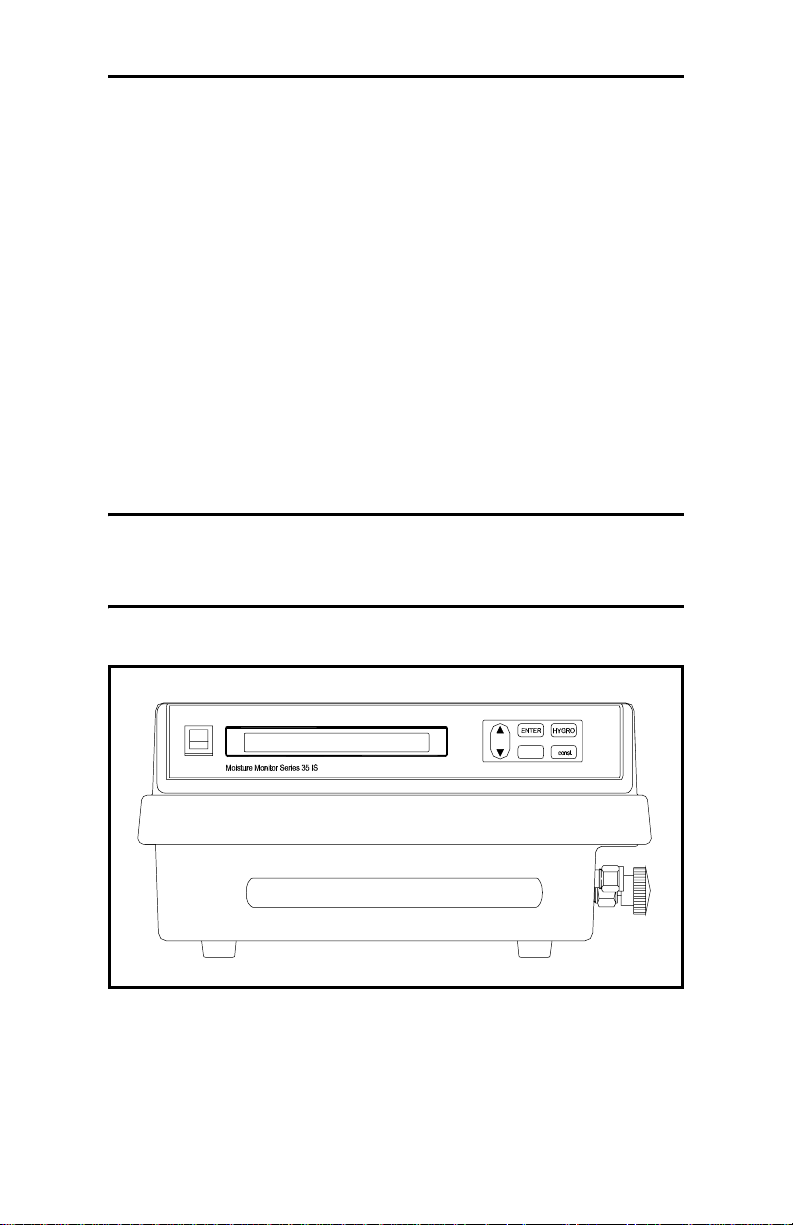
Both Series 35 IS configurations display measurement data on a
one-line, 16-character alpha-numeric LCD display screen. All
probe informatio n is entered into the unit usi ng the programming
keys on the front panel keypad (see Figure 1-1 below). The
Series 35 IS operates on an interna l 6 VDC battery, and t he unit
can operate while being charged with a 12 VDC charger.
Caution!
Do not use AC power in hazardous areas. Charge
the battery only in a no n-hazardous area.
POWER
P
ESC
Figure 1-1: Series 35 IS Front Panel
1-2 Features & Capabi lities
Page 11
March 2003
Moisture Probes
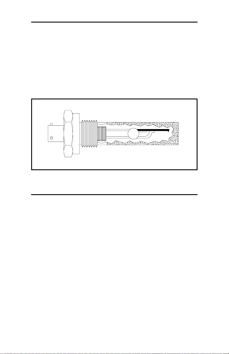
The moisture probe is the part of the system that comes in cont act
with the process, and is usually installed in a sample system. The
Series 35 IS uses any M Series probe to measure dew point
temperature in °C or °F. A sensor assembly is secured to the
probe mount and protected with a sinte red sta inless steel shield
(see Figure 1-2 below). Other types of shields are available.
Figure 1-2: The M Series Probe
The Sample System
The sample system conditions or controls a sample stream to the
specificati on s of the m eas urement probe. Typically, the sample
system is kept very simple, with as few component s as possible
located upstream of the measurement probe. The sample system
may include a filter to remove particulates from the sample
stream and/or a pressure regulator to reduce or control the
pressure of the sample stream. In gene ral, stainless steel is the
preferred material for all the sample system’s wetted parts.
If it was specified at the time of purchase, your Series 35 IS will
include a self-contained sa mple system.
Features & Capabi li ties 1-3
Page 12

March 2003
The User Pr o gram
The Series 35 IS contains a user program that en abl es you to
change moisture calibration data and selec t a number of userdefined program functions.
All functions and feature s of the Series 35 IS user program are
discussed in Chapter 3, Operating the Series 35 IS.
1-4 Features & Capabi lities
Page 13

March 2003
Chapter 2
Installing the Series 35 IS
This chapter d isc uss es ins tal l ing the Series 35 IS in all its
configurations. Use the following list of procedures to help you
install your unit.
Depending on the type of unit you have, refer to the appropriate
section(s) that fo llow to install your Series 35 IS correctly.
Installing your Seri es 35 IS consists of the following proc edures:
• Choosing a Measurement Site [page 2-2]
• Moisture Probe Considerations [page 2-3]
• Sample Sys tem G u ide lin es [p ag e 2 -5]
• Mounting an External Sample System [pag e 2-6]
• The Self-Contained Sample System [page 2-7]
• Installing a Probe into a Sample System [page 2-8]
• Making External Probe Connections [page 2-11]
Proceed to the appropriat e sec tion to install your Series 35 IS.
Installing the Series 35 IS 2-1
Page 14

March 2003
Choosing a Measurement Site
You should have disc ussed environmental factors with a GE
Panametrics applications engine er or field sales person before
you receive your Series 35 IS. The equipment should be sui ted to
both the application and the measurement site.
Read the following guide lines to verify th at you have se lected t he
best measurement site.
• Choose a measurement site for the probe and sa mple syste m as
close to the process line as possi ble. Avoid long lengths of
connecting tubing. If long distances are unavoidable, a fastsampling bypass loop is recommende d.
• Do not install any other components, such as filters, upstre am
of the probe or sample system unless instruc ted to do so by GE
Panametrics. Many common components, suc h as filters and
pressure reg ulators, are not suitable for sample systems. These
components contain wett ed parts that may absorb or release
materials (e.g. , moi sture) into the sample stream or allow
ambient contamination to e nter the sample stream. In general,
use stainless-s teel for all parts in contact with the sample.
• Observe all normal safety precautions. Use the probes within
their maximum pressure and tempera ture ratings.
• Do not expose the electronic s unit to high te mperatur es, strong
electrical transients, mechanical vibrations, corrosive
atmospheres, or any other conditions that could damage or
interfere with the Seri es 35 IS operation. See Chapter 5,
Specifications, for limits.
• If you are using an external sample system, you should
observe the proper cable restrictions for the probes. The M
Series probes require specially shielded cable. For units with
separate sample system s, you can locate the M Series probes
up to 100 meters (330 feet) from the Series 35 IS.
• Protect the probe cables from excessive strain (bending,
pulling, twisting, etc.). In addition, do not subject the cables to
temperatures above 65°C (149°F) or below –50° C (–58°F).
2-2 Installing the Seri es 35 IS
Page 15

March 2003
Moisture Probe Considerations
The M Series probes consist of an alu minum oxide se nsor l ocated
on a connector and covered by a protective stainless-steel shield.
The probe sensor material s and housing maximize durability an d
minimize water absorbing sur faces in the vicinity of the
aluminum oxide surface. A sintered sta inless-steel shield protects
the sensor from high flow rates and particulate matter (other
shields are available ) . Do not remov e the shield except upon
advice from GE Panametrics.
The sensor design permits the device to withstand normal shock
and vibration. Be sure t o avoid touching the active sensor surface
or allowing it to come into direct contac t with foreign objects.
Such contact may ad v ersel y aff ect pe rformance.
Observing these precau tions should ensure a long and useful
probe life. GE Panametrics recommends that you check probe
calibration routinely, at one-yea r int ervals, or as rec ommended by
the applications engineers for your particular application.
Because the probe measures water vapor pressure in its
immediate vicinit y, proximity to the system walls, materials of
construction, and other environmental factors can influence
readings. You can operate the sensor under vacuum or pressure
and under dynamic or static condi tions. Observe the following
environmental precautions.
1. Tempera ture Ran g e: the standard probe is operable from
–110°C to +70°C (–166°F to +158°F).
2. Moisture Condensation : be sure the temperature is at least
10°C higher than the dew/frost point temperature. If this
condition is not maintai ned, moisture condensation could
occur on the sensor or in the sample system and cause reading
errors. If reading errors occur, refer to “Aluminum Oxide
Probe Maintenance” in Appendix A.
Installing the Series 35 IS 2-3
Page 16

March 2003
Moisture Probe Considerations (cont.)
3. Static or Dynamic U se: the sensor perform s equally well in
still air or where con sid er ab le flow o ccurs . Its smal l size
makes it ideal for measuring moist ure conditions within
completely sealed cont ainers or dry boxes. It also performs
well under gas flow li near ve lociti es as hi gh as 10,0 00 cm/sec,
and liquid flow linear velocities to 10 cm/sec. Refer to Tables
A-2 and A-3 in Appendix A for maximum gas and liquid flow
rates.
4. Pressure: the moisture probe always sens es the exist ing water
vapor pressure regardless of the total ambient pres sure. The
moisture sensor measure s water vapor under vacuum or high
pressure conditions from as little as a few microns Hg to as
high as 5000 psi total pressure .
5. Long-Term Storage & Operational Stability: continuous
abrupt humidity changes do not affect the sensor, and
exposure to satura tion conditions does not damag e the sensor,
even when sto red.
6. Freedom from Interference: the pr esence of a wid e var iety
of gases or organic liquids does not affect the sensor. Also,
large concentrations of hydrocarbon gases, Freon®, carbon
dioxide, carbon monoxide, a nd hydrogen do not affect sensor
water vapor indications. The sensor functions pr operly in a
multitude of gaseous or non-c onductive liquid environments.
7. Corrosive Mat erials: avoid all materials that are corrosive or
otherwise damaging to alumin um or aluminum oxide. These
include strongly acidic or basic materials and primar y amines.
Freon is a registered tr ademark of E.I. du Pont de Nemours and Company.
2-4 Installing the Seri es 35 IS
Page 17

March 2003
Sample System Guidelines
A sample system, although not mandatory, is highly
recommended for moisture measur ement. The purpose of a
sample system is to condition or control a sample stream to
within the spe cifications of the probe. The application
requirements dete rmine the design of the sample system. GE
Panametrics applications engine ers can make recommendations
based on the following general guidelines:
• Typically, keep the sample sys tem simple. Include as few
components as possible and loca te all or most of the
components downstream of the measure ment probe. A simple
sample system consists of an explosion-proof housing with a
sample cell, a filter, and inlet and outlet needle va lves.
• Do not use any material for sample system components that
can affe ct measur ements. A sample sy stem may inc lu de a f ilter
to remove particulat es fro m the sample stream and/or a
pressure regulator to reduce or control the pressure of the
stream. However, most common filters and pressure re gulators
are not suitable for sample syste ms because their wetted parts
may absorb or release components (such as moisture) into the
sample stream. They may also allow ambient contamination to
enter the sample stream. In general, use stainless-steel for all
wetted parts.
Note: The actual sam ple system design depends on the
application requirements.
Installing the Series 35 IS 2-5
Page 18

March 2003
Mounting an External Sample System
Note: If you have a Series 35 IS with a self-containe d sample
system, disregard this section and p roceed to The SelfContained Sample System on page 2-7.
The sample sys tem is usually fastened t o a me tal pla te that ha s
four mounting holes. GE Panametrics can provide the sample
system in an enclosure, if reque sted. Sample system outline and
dimension drawings are included in your shipment, if you
ordered them.
Use the following steps to mount the external sample sys tem and
connect it to the process:
1. Fasten the sam ple sys tem p lat e or encl os u re to a soli d stab l e
surface with bolts and washers in each of its four corners.
2. Connect the process supply a nd return lines to the sample
system inlet and outlet using the required stainless-st eel
fittings and tubing.
Caution!
Do not start a flow through the system until the
probe h as been properl y ins tall ed.
Note: For common applications, GE Panametrics ca n pr ovide a
standar d sample system. If applicable, additional
instructions on how to start up and shut down the sample
system may be included.
2-6 Installing the Seri es 35 IS
Page 19
March 2003
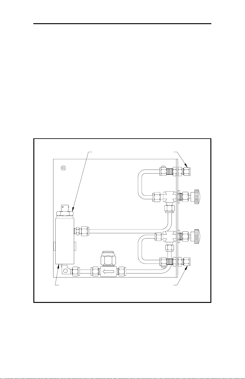
The Self-Contained Sample System
The Portable Series 35 IS can include a self-contained sample
system as shown in Appendix B. This sample system is
constructed with 1/4" Swagelok® inlet and outlet compression
fittings and 1/4" stainless-ste el tubing.
The sample system also includes inle t and outlet needle valves
and a 7-micron sintered stainless-steel filter with a replaceable
element. All wetted parts are Series 300 stainless steel, Viton®,
or Teflon®. The maximum allowable pressure for the sample
system is 4500 psig. See Figure 2-1 below.
Probe Outlet
Sample Cell
Inlet
Figure 2-1: Self-Contained Sample System with Probe
Swagelok is a registered trademark of Crawford Fitting Company.
Teflon is a registered trademark of E.I. du Pont de Nemours and Company , Inc.
Viton is a registered t rademark of DuPont Dow Elastomers, L.L.C.
Installing the Series 35 IS 2-7
Page 20
March 2003
Installing a Probe into a Sample System
The sample system design protect s the aluminum oxide moisture
probe from particulates and is recommended for process gases
such as dry instrument/pl ant air or other similar process gas.
Other sample handling equipment ( pr essure regulators, cooling
coils, additional filte rs, pressure gauges, rota- meters, etc.) may be
required for some applications. Contact GE Panametrics or see
Appendix A for general information about using GE
Panametrics’ Aluminum Oxide Moist ure Probe. Proceed to the
appropriate probe insta llation sect ion for your system.
Caution!
If you mount the probe directly into the process line,
cons ult GE Panametri c s f or proper installation
instruct ions and prec autions.
External Sample System
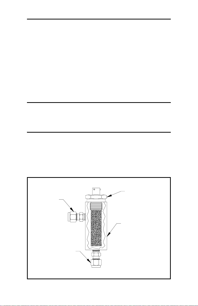
Use the following steps to inst all the probe into the external
sample cell. Refer to Figure 2-2 below.
Probe
Inlet
Sample Cell
Outlet
Figure 2-2: A Typical Probe Insta llation
2-8 Installing the Seri es 35 IS
Page 21

March 2003
External Sample Syst em (cont.)
1. Insert the probe int o the sample cell so that it is perpendic ular
to the sample inlet.
IMPORTAN T: For maximum protection of the aluminum oxide
sensor, always leave the shield in place.
2. Screw the probe into the receptacle fitting, making sure not to
cross the threads.
Note: M2 probes have 3/4- 16 straight threads with an o-ring
seal for installation either into the sample system or
dir ectly into the process line. Other mounts are available
for special applications.
3. Hand-tighten the probe in a clockwise direction , then tighten it
an additional 1/8 turn with a wrench .
Figure 2-2 on page 2-8 shows a typical probe install ation wi th the
probe mounted into a sample cell.
Installing the Series 35 IS 2-9
Page 22

March 2003
Self-Contained Sample System
Use the following steps to install the pro be into the sample cel l of
a self-contained sa mple syste m:
1. Loosen the two quarter -turn screws on the back of the
Series 35 IS cover.
2. Remove the cover b y gently lifting it off the unit from back to
front. Be careful not to pull on the cable s that connect to the
cover.
3. Insert the probe into the sample cell.
4. Screw the probe into the receptacle fitting, making sure not to
cross the threads.
Note: Insert the probe into the cylindrical shaped container
called the sample cell, which is included as part of your
sample system. M2 probes have 3/4-16 straight threads
and an o-ring seal for installa tion of the pro be into the
standar d sample cell (see Figure 2-1 on page 2-7).
5. Hand-tighten the probe in a clockwise direction , then tighten it
an additional 1/8 turn with a wrench .
6. Connect the blue probe cable to the probe by inserting the
bayonet-type connector onto the probe and twisting the shell
clockwise until it snaps into a locked position.
Note: The connector on the probe cable must be rotated until it
aligns with the pins in the probe connector, before the
cable may be properly inserted into the probe and
secured.
7. Close the Series 35 IS cover and tighten the two quarter-turn
screws on the back of the cover.
2-10 Installing the Series 35 IS
Page 23
March 2003
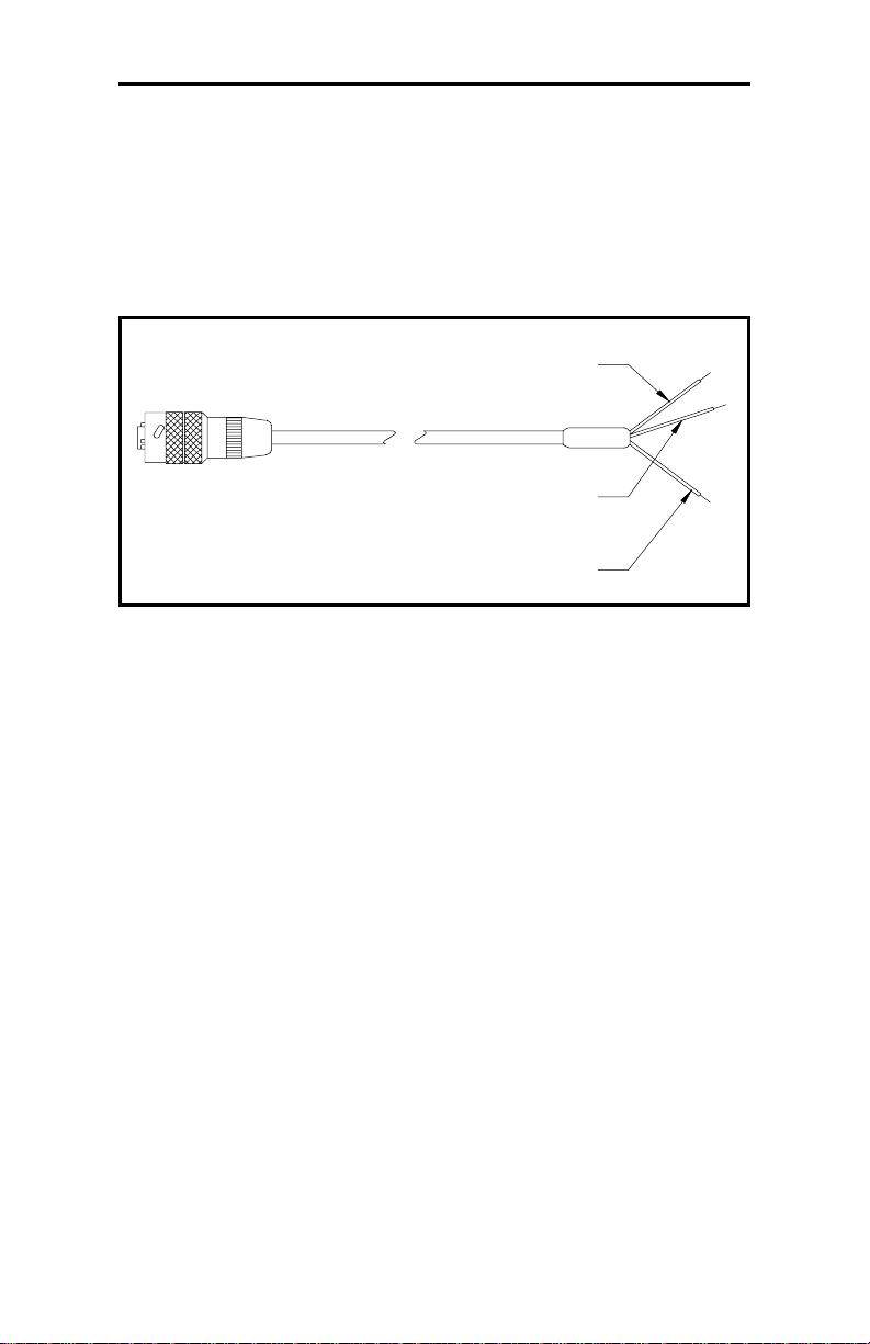
Making External Probe Connections
Probe connections may differ, depending on the type of sample
system you are using. Connect the moisture probe using a
continuous run of GE Panametrics two-wire shielded cable (see
Figure 2-3 below).
Red
Shield
Green
Figure 2-3: Two-Wire Shielded Cable
Protect all cables fr om excessive strain (bending, pulling, etc.).
Do not subject cables to temperat ures above +65°C (149°F) or
below –50°C (–58°F). You can order standard cable assemblies
(including connector s) from GE Panametrics in any length up to
100 meters (330 feet).
Use the following steps to make probe connections:
Note: Probe conn ections for an internal sampl e system have
been described in the previous section. The following
instructions are for an external sample system only.
1. Turn off the Series 35 IS.
2. Connect the cable to the probe by insert ing the bayonet-type
connector ont o the probe and twist ing the shell cloc kwise until
it snaps into a locked position.
Installing the Series 35 IS 2-11
Page 24

June 2004
Making External Probe Connections (cont.)
Note: The connector on the probe cable must be rotated until it
aligns with the pins in the probe connector, before the
cable may be properly inserted into the probe and
secured.
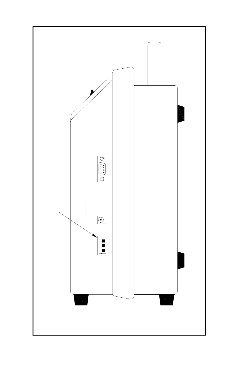
3. Connect the other end of the probe cable to the terminal block
on the Series 35 IS side panel (see Table 2-1 below and
Figure 2-4 on page 2-13).
IMPORTAN T: To maintain good contact at each terminal block
and to avoid damagi ng th e pins on the c onnec tor,
pull the connector strai ght off (not at an angle),
make cable connections while the connector is
away from the unit, and push the connector
straight on (not at an angle) when the wiring is
complete.
NOTICE FOR BASEEFA CERTIFICATION
The M Ser ies probe may not be c apable of
withstand ing the 500 V ins ulation test required
by clause 5.7 of EN50 020 when installed in the
proces s m edia. This must be taken into acco unt
in any ins tal lat ion in which it is u se d.
(See Cert. #Ex95C2002X in its entirety.)
Table 2-1: Probe Connections
To PROBE
Connect:
Red (H2) wire pin 1
Shield pin 2
Green (H1) wire pin 3
2-12 Installing the Series 35 IS
Terminal Block
Page 25
k
c
o
l
B
l
a
n
i
m
r
e
T
e
b
o
r
P
June 2004
R
2
S
3
E
2
A
G
S
E
R
R
R
A
A
H
S
C
U
E
O
S
D
U
R
T
A
O
Z
A
N
H
O
N
D
I
-
2
3
G
2
N
I
S
N
R
R
R
A
O
R
W
E
G
R
A
H
C
T
U
3
P
N
I
2
E
B
1
O
R
P
Figure 2-4: Probe Te rminal Block Location
Installing the Series 35 IS 2-13
Page 26

June 2004
Using Modified or Non-GE Panametrics Cables
In some installations, it may be desirable to use a pre-existing
moisture cable or to modify the standard GE Panametrics
moisture cable. If this a pproach is taken, it is essential that the
following precaution s be observed. Further more, after connectin g
the moisture probe, a calibration adjustm ent must be performed
to compensate for any electrical offset s introduced by the nonstandard cable .
Caution!
GE Pana m et ric s c annot guarantee operation
of the Ser ies 35 IS to the spe c ifi ed accuracy
unless a s tan dard GE Pana m et ric s
hygrome t er c able is used.
1. Use cable that matches the electrical characteristics of GE
Panametrics cable (contact the factory for specific information
on cable characteristics).
2. If possible, avoid all splices. Splices will
impair the
performance of the instrum ent. When possible, instead of
splicing, coil the excess cable.
3. If you must splice cables, be sure the splice introduces
minimum resistive leakage or capac itive coupling between
conductors.
4. Carry the shie ld through any splice. A common mistake is to
not connect the shields over the splice. If you are modifying a
GE Panametrics cable, the shield will not be accessible
without cutting ba ck the cable insulation. Also, do not
ground
the shield at both ends. The shi eld should be grounded only at
the hygrometer end, as described in Table 2-1 on page 2-12.
2-14 Installing the Series 35 IS
Page 27

June 2004
Performing a Calibration Adjustment
After completing the installation of a modified or non-standard
moisture cable , it is necessa ry to perfor m a calibr atio n adjust ment
on the Series 35 IS. This procedure will adjust the electronics to
compensate for any error or offset introduced by splices or long
cable lengths. It is also recommended that a calibration be
performed after the installation of a new GE Panametrics cabl e,
to ver i f y the acc u r a cy of the unit.
Use the following steps to perfor m a calibr ation adjustment:
1. Power up the Series 35 IS.
2. To check the new cable, se t up the screen to display “MH”.
See Chapter 3, Operating the Series 35 IS, for instructions on
how to navigate through the user progra m.
3. Note the high, low and zero reference values that are recorded
on the sticker located on the inside of the Series 35 IS chassis.
4. Disconnect the cable from the probe only (leave the cable
connected to the Series 35 IS), and verify that the displayed
MH value equals the zero refere nce value within ± 0.0003 MH.
If this reading is within spe cifications, no further testing is
necessary.
5. If the zero refere nce value r eading above wa s out of range , the
low referenc e value must be adjusted . For readi n gs mo re tha n
0.0003 below the previously recorded zero reference value,
add the difference to the low reference value. For readings
more than 0.0003 above the previously recorded zero
reference value, subtract the difference from the low reference
value. Record the fi nal cor rec te d low refere n ce val u e.
6. Reprogram the Series 35 Is with the new, corrected low
reference value. See Entering High and Low Reference V al ues
in Chapte r 3.
7. Make sure the ca ble is still disconnected from the probe but is
connected t o the Seri es 35 IS.
Installing the Series 35 IS 2-15
Page 28

June 2004
Performing a Calibration Adjustment (cont.)
8. Recheck the zero reference reading and verify that it is now
within ±0.0003 MH of the previously recorded value.
9. Fill out a new reference sticker with the final low reference
value and/or record the information on the Data Information
Sheet in Appendix D. Make sure the following information is
included:
• HIGH REF = Original Value
• LOW REF = New Corrected Value
• ZERO REF = Original Recorded Value
10.Re co nn ect the cabl e t o the prob e .
Note: If the cable is changed in any way, repeat the above
proce dure for maximum accuracy of the unit.
The Series 35 IS is now ready for operation. Proceed to
Chapter 3, Operating the Series 35 IS.
2-16 Installing the Series 35 IS
Page 29

March 2003
Chapter 3
Operat ing the Series 35 IS
Your factory-programmed Series 35 IS can begin taking
measurements as soon as you turn the power on. The user
program enables you to enter and change setup information.
Note: The Series 35 IS suspends taking measurements when you
enter the user pr ogram listed below. Refer to the menu
map in Appendix C to navigate the user program.
This section explains the following procedures:
• Getting Started [page 3-2]
• Using the Keypad to Enter and Change Data [page 3-5]
• Verifying and Changing Factory Setup Data [pa ge 3-9]
• Changing the Measurement Displ ay [page 3-14]
• Entering an O ffset Value for Dew/Frost Point [pag e 3-1 5 ]
• Entering a Constant Pressure Value [page 3-16]
• Entering a PPMv Constant Multiplier [page 3-18]
• Entering an Interval for Automatic Calibration [page 3-19]
• Viewing the Battery Status [page 3- 21]
• Entering a Bac klig h t-O n Time Interval [pag e 3 -22 ]
• Setting Up Computer-Enhanced Response [page 3-23]
• Setting Up Range Error Processing [page 3-25]
• Selecting AC Line Frequency (60/50 Hz) [page 3-26]
• Adjusting the Contrast [page 3-27]
• Setting the Clock Values [page 3-28]
• Setting Up the Data Logger [ page 3-30]
Operating the Series 35 IS 3-1
Page 30

March 2003
Getting Started
Your unit is completely set up at the factory. To begin taking
measurements, you only need to apply power to the unit and start
up the sample system. Complete the instructions in the fol lowing
sections to get your unit up and runnin g:
• Starting Up and Shutting Down the Sample System
• Powering up the Series 35 IS
3-2 Operat ing the Series 35 IS
Page 31

March 2003
St art ing U p and Shu tti ng D own th e Sam ple S yste m
If your Series 35 IS has a self-contained sample system, use this
section to properly start up the sample system before you begin
taking measurements, and to shut down the sample system when
you have finished taking measurements.
Note: If you are using an external sample system, refer to the
separate manual supplied with your order.
Starting Up the Sample System
In order to operate the self-contained sample system correctly,
first dete rmine if you need to make measurements a t atmospheric
pressure or a t process pressure. After determining the pressure,
use the appropriat e section that follows to start up and shut down
the sample system.
Note: The maximum allowable pressure for the self-contained
sample system for the Series 35 IS is 4500 psig.
At Atmospheric Pressure:
1. Begin with the Series 35 IS inlet and outle t valves in the
closed position, then open the outlet
2. Open the inlet
valve slightly to allow only a small amount of
valve completely.
flow from the process.
At Proce ss Pressure:
1. Begin with the Series 35 IS inlet and outle t valves in the
closed position, then slowly open the inlet
2. Open the outlet
valve slightl y to allow only a small amount of
valve fully.
flow.
Operating the Series 35 IS 3-3
Page 32

March 2003
Shutting Down the Sample System
At Atmospheric or Process Pressure:
1. Close the inle t valve completely.
2. Wait for the flow from the outlet valve to stop.
3. Close the outlet valve to keep the probe sensor from being
affected by ambient moisture.
Powering Up the Series 35 IS
T o turn on the Ser i e s 35 IS, press the POWER switch (located on
the left side of the front panel ) to the ON position. (If the battery
is depleted, see Ch ap ter 4, Troubleshooting, to recharge the
battery.)
The Series 35 IS displays “Load ing. . . .”, followed by a series of
additional screens. This indicates that the system is loading
calibration and refere nce data. After thi s da ta is l oaded, the Series
35 IS automatic ally calibrates (Autoc al) the moisture circuitry,
and then begins taking measurements.
3-4 Operat ing the Series 35 IS
Page 33

March 2003
Using the Keypad to Enter and Change Data
The Series 35 IS user program enables you to change factory setup data and user-def ined program functions .
Use the appropriate sections that follow to learn how to:
• Use the programming keys
• Enter and exit the user program
• Move through the user program
• Enter numeric data
How to Use the Programming Keys
The membrane keypad to the right of the display window on the
front panel of the Series 35 IS contai ns six (6) keys:
• ENTER - Use this key to: enter a menu option; switch from
viewing to editing data; move to the next digit position during
numeric entry; confirm an entry.
• ESC - Use this key to: cancel an entry; move back up one
level in the menu sequence.
• ∆ - This key scrolls upward through the menu options and
increases the value during numeric entry.
• ∇ - This key scrolls downward through the me nu options and
decreases the valu e dur ing num er ic entry.
• HYGRO - Press this key in measurement mode to display the
dew/frost point temperature in the selected units.
• P
pressure in the selected units.
Operating the Series 35 IS 3-5
- Press this key in measurement mode to display the
const
Page 34

March 2003
How to Enter and Exit the User Program
T o enter programming mode, perform the following sequenc e
within five (5) seconds, or the Series 35 IS will time out and
return to meas urement mode.
P: +0.00 Kcmg
ESC
While in measurement mo de,
press the
[ESC] key.
Within 5 seconds of the
appearance of th is display, press
the
[ENTER] key followed by
the
[ESC] key.
PROGRAM MENU
DP RANGE
This will display for 1 second.
You are now in the user progra m
menu.
From the main menu, use the arrow keys to scroll through the
options to your selecti on. Use the
selection or the
[ESC] key to cancel your selection.
T o exit the user program, press the
displays, the n press the
[ENTER] key to return to displaying
[ENTER] key to confirm your
[ESC] key until RUN ?
measurements.
DP RANGE
RUN?
Exiting......
P: +0.00 Kcmg
Press th e [ESC] key.
Press the [ENTER] key.
This will display for 1 second.
You have now returned to
measurement mode.
3-6 Operat ing the Series 35 IS
Page 35

March 2003
How to Move Through the U ser Program
Use the arrow keys to scroll through the f ollowing menu options.
Refer to the Menu Map (Figure C-1) in Appe ndix C as a guide,
while moving through the user progr am.
Note: While in the pr ogramming mode, the Series 35 IS
suspends taking measure ments.
• DP RANGE - Use to enter high and low dew points for the
calibration cur ve. This input determines the number of points
in the Moisture Probe Calibration Data entry, and shows the
maximum/minimum dew point values in degree s celsius (°C),
as shown on the Moisture Probe Calibration Data Sheet.
• MH CURVE - Use to enter a value for each point in the
calibration cur ve. This Moisture Probe Calibration Data Entry
accepts only MH values. The dew point automatically
increases at 10°C intervals.
• SERIAL # - Input the moisture probe seria l number.
• HYGRO REFERENCE - Use to enter high and low reference
values for moisture measurement.
• USER - Use to set up user-defined program functions, such as
offset value, constant pressure, PPMv multiplier, Autocal
interval, battery, backlight interval, computer enhanced
response (optional) , range error handling, selecting 60/50 Hz,
contrast, and clock.
• FACTORY SETUP - Used for GE Panamet ri cs fie ld serv i ce
and factory use only. A passcode is required to access this
function.
• LOGGER - This optional s ection lets you program the unit to
log data at pre-selected time intervals and access the logged
data for viewing or for sending to a dump terminal. It includes
log interval, log setup, log display, and log dum p settings.
Operating the Series 35 IS 3-7
Page 36

March 2003
How to Enter Numeric Data
To enter numbers one digit at a time, use the a rrow keys to scroll
to the desi red number, then press the
next digit position. Repeat this procedure until all numbers have
been entered.
Note: In the pr ogramming mode, pressing an arrow key lets you
enter the edit mo de. Pressing
mode without changing any data. In edit mode, check all
characters before pressing the
to the next digit position.
[ENTER] key to move to the
[ESC] termina tes the edit
[ENTER] key and moving
3-8 Operat ing the Series 35 IS
Page 37

March 2003
Verifying and Changing Factory Setup Data
Use this section to confir m, or make any necessary changes to,
the factory setup data. The setup data includes information
regarding the moisture probe as listed below:
• Dew point range
• Calibration data
• Probe serial number
• High and low reference values
Note: Remember to re cord all setup data in Appendix D, Data
Information Sheet, in the back of this manual.
The factory enters all the necessary data into your Series 35 IS.
Therefore, you should not need to re-e nter this data unless you
• Purchase a new probe
• Recalibrate an existing probe
• Have reason to believe the data is corrupted.
Use the appropriate sections that follow to verify and/or change
the setup data.
Operating the Series 35 IS 3-9
Page 38

March 2003
Entering the Dew Point Range
Use the DP RANGE to enter high and low dew point values. The
Series 35 IS uses this range to determi ne the number of points in
the calibration curv e.
Note: Enter the user program as described on page 3-6.
DP RANGE
Hi DP
Use the arrow keys to scroll to
DP RANGE and press the
[ENTER] key.
Scroll to th i s sc reen w ith the
arrow keys and press the
[ENTER] key.
Hi DP +20°C
Use the arrow keys to scroll to
the desired dew point value, then
press the
[ENTER] key.
Note: The high and low dew points are listed on the Moisture
Probe Cali bration Data Sheet located in the probe box.
The default values are: Low = -110°C, High = +20°C.
Hi DP
Low DP
Low DP -110° C
Press the down arrow key.
Press the [ENTER] key.
Use the arrow keys to scroll to
the desired value. Then, press
the
[ENTER] key.
Low DP
Press [ESC] to return to the main
menu, and proceed to the next
section.
IMPORTAN T: If you change the dew point settings, you must
change the calibration curve also.
3-10 Operating the Series 35 IS
Page 39

March 2003
Entering Calibration Data
After entering the high and low dew point val ues, use the MH
CURVE
accordance with the following procedure.
Note: Remember to re cord all set-up data in Appendix D, Data
Moisture probe calibr ation data is taken at fixed dew point val ues
in 10°C intervals. After the high and low dew point values have
been entered, the appropriate number of da ta points for the
moisture probe is automati cally determined. Starting with the
minimum dew point value, the MH values must be entered in
10°C increments until the maximum dew point is reached.
Note: Changing the dew point setting affe cts the MH curve.
option to enter calibration data for the moistur e probe in
Informati on Sheet, in the back of this manual.
MH CURVE
-1 10°C MH 0.1890
Use the arrow keys to scroll to
MH CURVE and press the
[ENTER] key.
Press the arrow keys to scroll
through the
[ENTER] then the a r row keys to
edit a value. (
mode and
MH values. Press
ED displays in edit
MH displays in view
mode.) Using the arrow keys
and the
[ENTER] key, edit the
value one digit at a time, and
then press
[ENTER].
Note: To abort the editing functio n at any time wi thout changing
the value, press th e
[ESC] key.
Repeat the above procedure for each point in the MH Curve.
Then, press
[ESC] until you return to main menu and proceed to
the next section.
Operating the Series 35 IS 3-11
Page 40

March 2003
Entering the Probe Serial Number
The probe serial number is liste d on the Calib ration Data Sheet
and is inscribed on the hex nut of the moisture probe.
Note: Remember to re cord all set up data in Appendix D, Data
Informati on Sheet, in the back of this manual.
USER
SERIAL #
xxxxxx S/N
123456 S/N
From the main menu, use the
arrow keys to scroll to the
prompt, then press the
USER
[ENTER]
key to view the options.
Use the arrow keys to scroll to
SERIAL # and press the
[ENTER] key.
The unit displays the current
serial number.
T o edit the serial number, press
an arrow key a nd a blinking
cursor appear s at the le ft-most
digit. Use the arrow keys to
scroll to the desired value and
press
[ENTER] to move the
cursor to the next digit. Repeat
until you have entered all six
serial number digits . Pre ss the
[ENTER] key to confirm the
change or the
[ESC] key to
cancel the change.
SERIAL #
Press the [ESC] key to ret urn to
the main menu.
T o enter more setup data, proceed to the appropriate section of
this manual. To return to measurement mode, press
the
RUN ? prompt appears and then press the [ENTER] key.
3-12 Operating the Series 35 IS
[ESC] until
Page 41

March 2003
Entering High and Low Reference Values
The Series 35 IS requires high and low reference values for its
moisture measurement circuitry. These factory calibration values,
specific to each unit, are listed on a label inside the unit.
IMPORTAN T: Do not change the high and/or low reference
values unles s instr uct ed to do so by GE
Panametrics.
Note: Remember to re cord all setup data in Appendix D, Data
Informati on Sheet, in the back of this manual.
HYGRO REFERENCE
High REF
HX.XXXX
Use the arrow keys to scroll to
HYGRO REFERENCE and
press the
[ENTER] key.
Press either arrow key to scroll
to the
High REF option, then
press the
[ENTER] key.
Use the arrow a nd [ENTER] keys
to change the valu e one digit at a
time, then press
[ENTER].
Note: To abort the editing functio n at any time wi thout changing
the value, press th e
Low REF
LX.XXXX
[ESC] key.
Press either arrow key to scroll
to the
Low REF option, then
press the
[ENTER] key.
Use the arrow a nd [ENTER] keys
to change the valu e one digit at a
time, then press
[ENTER].
Operating the Series 35 IS 3-13
Page 42

March 2003
T o enter more setup data, proceed to the appropriate section of
this manual. To return to measurement mode, press
the
RUN ? prompt appears and then press the [ENTER] key.
[ESC] until
Changing the Measurement Display
The front panel of the Series 35 IS contains two ke ys that let you
quickly change the L.C.D. display mode during operation of the
unit. These display keys are labeled
HYGRO and P
const
.
• HYGRO - Press this key to display and scroll through all the
available moistur e measurement units (DP/°C, DP/°F, PMv,
MH).
• P
- Press this key to display and scroll through all
const
available consta nt pressure units (PSG, Bar, KPAg, Kcmg).
After you select a specific display mode , that display remains on
the screen until you choose anot her display mode or until you
enter the programming mode. Upon exiting the programming
mode and returning to measurement mode, the screen
automatically retur ns to the previously selected dis play mode.
3-14 Operating the Series 35 IS
Page 43

March 2003
Entering an Offset Value for Dew/Frost Point
Use this option to a djust the displayed dew/frost point reading. A
positive number increa ses the reading and a negative number
decreases the readi ng. The offset value always displays in dew/
frost point degrees C.
Note: Enter the user program as described on page 3-6.
USER
From the main menu, use the
arrow keys to scroll to the
prompt, then press the
USER
[ENTER]
key to view the options.
OFFSET
Use the arrow keys to scroll to
OFFSET and press the [ENTER]
key.
OFFSET +5.0 °C
The current offset value is
displayed.
OFFSET +10.0 °C
Press either arrow key to delete
the current value and enter the
edit mode. Use the arrow an d
[ENTER] keys to change the
value one digit at a time, then
press the
[ENTER] key.
Note: To abort the editing functio n at any time wi thout changing
the value, press th e
[ESC] key.
OFFSET
Press the [ESC] key to ret urn to
the main menu.
T o enter more setup data, proceed to the appropriate section of
this manual. To return to measurement mode, press
the
RUN ? prompt appears and then press the [ENTER] key.
Operating the Series 35 IS 3-15
[ESC] until
Page 44

March 2003
Entering a Constant Pressure Value
This option lets you enter a fixed val ue for the pressure of the
sample gas at the moisture probe location. The value is used to
calculate the moistur e conte nt in
Note: Enter the user program as described on page 3-6.
PPM
.
v
USER
From the main menu, use the
arrow keys to scroll to the
prompt, then press the
key to view the options.
CONSTANT PRESSUR
KP PSIg
Use the arrow keys to scroll to
CONSTANT PRESSUR and
press the
[ENTER] key.
The current units choice is
displayed. Use th e arr ow keys to
scroll to the desired pres sure
units, then press the
key. See Table 3-1 below for the
available choices.
Table 3-1: Constant Pres su r e Units
Available Units Description of Units
KP psig pounds per square inch gauge
KP bar bars absolute
KP KPag kilopascals gauge
KP Kcmg kilograms per square centimeter gauge
USER
[ENTER]
[ENTER]
KP: +XXX.XX PSG
The current constant pressur e
value is displayed.
Note: To abort the editing functio n at any time wi thout changing
the value, press th e
3-16 Operating the Series 35 IS
[ESC] key.
Page 45

March 2003
Entering a Constant Pressure Value (cont.)
KP: +500.00 PSG
Press either arrow key to delete
the current value and enter edit
mode. Use the arrow and
[ENTER] keys to change the
value one digit at a time, then
press
[ENTER].
KP: +XXX.XX PSG
KP PSIg
The new constan t pressur e va lue
is displayed. Press
[ESC].
The current units choice is
displayed. Press
[ESC] to return
to the options menu.
CONSTANT PRESSUR
Press the [ESC] key to ret urn to
the main menu.
T o enter more setup data, proceed to the appropriate section of
this manual. To return to measurement mode, press
the
RUN ? prompt appears and then press the [ENTER] key.
[ESC] until
Operating the Series 35 IS 3-17
Page 46

March 2003
Entering a PPMv Constant Multiplier
Use this option to apply a user- defined constant multiplier to the
the PPMv value.
Note: Enter the user program as described on page 3-6.
USER
PPMv MULTIPLIER
KPPMv 1.0000
KPPMv X.XXXX
PPMv MULTIPLIER
From the main menu, use the
arrow keys to scroll to the
prompt, then press the
USER
[ENTER]
key to view the options.
Use the arrow keys to scroll to
PPMv MULTIPLIER and press
the
[ENTER] key.
The current value is displa yed.
Press either arrow key to delete
the current value and enter the
edit mode.
Use the arrow a nd [ENTER] keys
to enter the new multiplier, one
digit at a time. Then , pres s
[ENTER] twice to return to the
options menu.
Press the [ESC] key to ret urn to
the main menu.
Note: PPMv constant multiplier values up to 999.9999 may be
enter ed, but the value should be set at 1.0000 unless
otherwise advised by GE Panametric s. Be sure to record
all enter ed data in Appendix D, Data Information Sheet, in
the back of this manual.
T o enter more setup data, proceed to the appropriate section of
this manual. To return to measurement mode, press
the
RUN ? prompt appears and then press the [ENTER] key.
3-18 Operating the Series 35 IS
[ESC] until
Page 47

March 2003
Entering an Interval fo r Au to matic Calibration
The Series 35 IS automatically calibrates itself (Autocal) at userprogrammable time inte rvals, in orde r to compensa te for a ny drift
in the electronics . An Autocal interval value between 0 and 1440
minutes (24 hours) m ay be enter ed. GE Panametr ics re commends
setting the Autocal int erval to eight hours (480 minutes). If the
Series 35 IS is exposed to extreme temperatures or weather
conditions, a shorter Autocal interval may be more appropriate.
Note: Enter the user program as described on page 3-6.
USER
AUTOCAL INT ERVAL
ACAL (Mins) 30
ACAL (Mins) XX
AUTOCAL INT ERVAL
From the main menu, use the
arrow keys to scroll to the
prompt, then press the
USER
[ENTER]
key to view the options.
Use the arrow keys to scroll to
AUTOCAL INTERVAL and pr ess
the
[ENTER] key.
The current Autocal interval
value is displayed.
Press either arrow key to delete
the current value and enter the
edit mode. Use the arrow an d
[ENTER] keys to change the
value one digit at a time, then
press
[ENTER] to return to the
options menu.
Press the [ESC] key to ret urn to
the main menu.
T o enter more setup data, proceed to the appropriate section of
this manual. To return to measurement mode, press
the
RUN ? prompt appears and then press the [ENTER] key.
Operating the Series 35 IS 3-19
[ESC] until
Page 48

March 2003
Entering an Interval for Automatic Calibration
(cont.)
After you confirm the Autocal interval a nd return to the main
menu, the Series 35 IS immediately performs an Autocal. The
next time Autocal occurs depends on the length of the time
interval setti ng.
The Series 35 IS determines the times of subsequent Autocals by
establishing a fixed schedule, beginning at midnight, using the
specified inter val. For example, if you enter a 90-minute time
interval, Auto ca l occu r s 16 times p er day
(1 day = 1440 minutes ÷ 90 minutes = 16).
The following fixed schedul e applies:
1. 1:30 a.m. 9. 1:30 p.m.
2. 3:00 a.m. 10. 3:00 p.m.
3. 4:30 a.m. 11. 4:30 p.m.
4. 6:00 a.m. 12. 6:00 p.m.
5. 7:30 a.m. 13. 7:30 p.m.
6. 9:00 a.m. 14. 9:00 p.m.
7. 10:30 a.m. 15. 10:30 p.m.
8. 12:00 p.m.(noon) 16. 12:00 a.m.(midnight)
If you enter a time interval not evenly divisible into 1440
minutes, the Series 35 IS rounds up to the next acceptable
interval. For example, if you set the 90- minute Autoc al int erval a t
6:10 p.m., the next Autocal occurs at 7:30 p.m. (excluding the
Autocal performed when you exit the Autoc al menu).
3-20 Operating the Series 35 IS
Page 49

March 2003
Viewing the Battery Sta tus
Make sure that the batte ry cha rge r is disconne cted be fore v iewing
the battery status.
Note: Enter the user program as described on page 3-6.
USER
BATTERY
DISCONNECT A.C.
Press ENTER
BAT: +6.89 V
BA T: 100%
BATTERY
From the main menu, use the
arrow keys to scroll to the
prompt, then press the
USER
[ENTER]
key to view the options.
Use the arrow keys to scroll to
the
BATTERY option and press
the
[ENTER] key.
The display alternat es between
the two messages shown. Press
the
[ENTER] key when the AC
power has been disconnected.
The display alternat es between
the two messages shown. Press
the
[ESC] key to return to the
options menu.
Press the [ESC] key to ret urn to
the main menu.
T o enter more setup data, proceed to the appropriate section of
this manual. To return to measurement mode, press
the
RUN ? prompt appears and then press the [ENTER] key.
Operating the Series 35 IS 3-21
[ESC] until
Page 50

March 2003
Entering a Backlight-On Time Interval
Your Series 35 IS is equipped with a backlight, which can be
programmed to turn off aut omatically after a pre-determined
time. Values between 0 and 1440 minutes (24 hours) may be
entered.
Note: Enter the user program as described on page 3-6.
USER
BACKLIGHT
BLITE (Mins) 30
BLITE (Mins) XX
BACKLIGHT
From the main menu, use the
arrow keys to scroll to the
prompt, then press the
USER
[ENTER]
key to view the options.
Use the arrow keys to scroll to
BACKLIGHT and press the
[ENTER] key.
The current backlight inte rval
value is displayed.
Press either arrow key to delete
the current value and enter the
edit mode. Use the arrow an d
[ENTER] keys to change the
value one digit at a time, then
press
[ENTER] to return to the
options menu.
Press the [ESC] key to ret urn to
the main menu.
Note: Constant use of the backlight shortens the battery life. All
units ar e shipped wit h a default bac klight-on ti me int erval
of 5 minutes.
T o enter more setup data, proceed to the appropriate section of
this manual. To return to measurement mode, press
the
RUN ? prompt appears and then press the [ENTER] key.
3-22 Operating the Series 35 IS
[ESC] until
Page 51

March 2003
Setting Up Computer-Enhanced Response
Note: This option may not be installed on your Seri es 35 IS.
Using a dynamic moisture calibr ation technique, ComputerEnhanced Response extrapolates the moisture level to the end
point, when making measurements in abrupt “dry down”
conditions. Response time depends on the relative change in dew
point. For example, the Series 35 IS can respond in three to f ive
minutes to reflect a change from ambient moisture to trace levels.
The accuracy of Computer -Enhanced Response equals ±2°C of
the sensor reading, assuming an equilibrium with the gas. To
ensure accuracy, your application should:
• Have a reasonably constant f low rate and final dew point.
• Maintain a minimum flow rate of one standard cubic foot per
hour (SCFH).
• Operate at atmo sp h eric p res su re (0 psi g )
• The actual moisture content mus t be above –85°C frost point
and must be stable.
You can enable or disable the Computer-Enhanc ed Response
feature. If the feature is not available, the display reads
Not Avail
Note: Enter the user program as described on page 3-6.
USER
ENHANCE RESPO NSE
Operating the Series 35 IS 3-23
. Otherwise, the Enhance Response display appears.
From the main menu, use the
arrow keys to scroll to the
prompt, then press the
key to view the options.
Use the arrow keys to scroll to
the
ENHANCE RESPONSE
option and press the
key.
Option
USER
[ENTER]
[ENTER]
Page 52

March 2003
Setting Up Computer-Enhanced Response
(cont.)
ENHANCE OFF
Use the arrow keys to scroll to
one of the option screens shown
ENHANCE ON
ENHANCE RESPO NSE
and press the
[ENTER] key.
Press the [ESC] key to ret urn to
the main menu.
Note: An activated Computer Enhanced Resp onse displays a
reverse video “E” on the left side of the display. After
determining the final va lue, the reverse video “E”
changes to a regular “E”.
T o enter more setup data, proceed to the appropriate section of
this manual. To return to measurement mode, press
the
RUN ? prompt appears and then press the [ENTER] key.
[ESC] until
3-24 Operating the Series 35 IS
Page 53

March 2003
Setting Up Range Error Processing
Range errors occur when an input signal within the capacity of
the analyzer is outsi de the ra nge of t he probe cali br ation data . The
Series 35 IS displays Range Errors with a n
UNDER RANGE message. The error condition extends to all
OVER RANGE or
displayed measurements of that mode. For example, if dew point
displays
OVER RANGE.
OVER RANGE, then moisture in PPMv also displays
There are two available Range Error processing options:
• No Action - the range error is not displaye d.
• Display - the range error is displayed.
Note: Enter the user program as described on page 3-6.
USER
From the main menu, use the
arrow keys to scroll to the
prompt, then press the
USER
[ENTER]
key to view the options.
RANGE ERROR
R_ERR = Display
Use the arrow keys to scroll to
the
RANGE ERROR option and
press the
[ENTER] key.
Use the arrow keys to scroll to
one of the options shown and
R_ERR = No Action
RANGE ERROR
press the
[ENTER] key.
Press the [ESC] key to ret urn to
the main menu.
T o enter more setup data, proceed to the appropriate section of
this manual. To return to measurement mode, press
the
RUN ? prompt appears and then press the [ENTER] key.
[ESC] until
Operating the Series 35 IS 3-25
Page 54

March 2003
Selecti ng AC Line Frequency (60/50 Hz)
Select this setting acc ording to the AC line frequency in the
country where the Series 35 IS is installed.
Note: Enter the user program as described on page 3-6.
USER
From the main menu, use the
arrow keys to scroll to the
prompt, then press the
USER
[ENTER]
key to view the options.
SELECT 60/50 HZ
60HZ
Use the arrow keys to scroll to
the
SELECT 60/50 HZ option
and press the
[ENTER] key.
Use the arrow keys to scroll to
one of the options shown and
50HZ
SELECT 60/50 HZ
press the
[ENTER] key.
Press the [ESC] key to ret urn to
the main menu.
Note: For refe rence, recor d all entered data in Appendix D,
Data Inform ati on Sh ee t , in the back of this manual.
T o enter more setup data, proceed to the appropriate section of
this manual. To return to measurement mode, press
the
RUN ? prompt appears and then press the [ENTER] key.
[ESC] until
3-26 Operating the Series 35 IS
Page 55

March 2003
Adjusting the Contrast
Use this option to adapt to the lighting conditions of the Series 35
IS installation.
Note: Enter the user program as described on page 3-6.
USER
CONTRAST
Adj. Contrast
CONTRAST
From the main menu, use the
arrow keys to scroll to the
prompt, then press the
USER
[ENTER]
key to view the options.
Use the arrow keys to scroll to
the
CONTRAST option and
press the
[ENTER] key.
Press the up-arrow key to
increase contrast o r the downarrow key to decrease, contrast.
Hold the key down for large
changes or press repeatedly for
small changes. Press the
[ENTER] key to confirm the new
setting.
Press the [ESC] key to ret urn to
the main menu.
T o enter more setup data, proceed to the appropriate section of
this manual. To return to measurement mode, press
the
RUN ? prompt appears and then press the [ENTER] key.
Operating the Series 35 IS 3-27
[ESC] until
Page 56

March 2003
Setting the Clock V alues
The Series 35 IS has no backup power source, and the time/date
must be reset wh enev er the ba tte ry has been tot all y dep let ed.
Note: Enter the user program as described on page 3-6.
USER
From the main menu, use the
arrow keys to scroll to the
prompt, then press the
key to view the options.
CLOCK
Read Time
hh:mm mm/dd/yy
Use the arrow keys to scroll to
the
CLOCK option and press the
[ENTER] key.
Use the arrow keys to scroll to
READ TIME then press the
[ENTER] key.
The current tim e an d date are
displayed for 2 seconds, before
the
CLOCK prompt returns.
T o edit the time, use the following steps:
CLOCK
Set Time
Press the [ENTER] key.
Use the arrow keys to scroll to
SET TI ME. Then, press the
[ENTER] key.
USER
[ENTER]
hh:mm
Use the arrow a nd [ENTER] keys
to scroll to the correct hour and
minutes values. Then, press the
[ENTER] key.
Set Time
3-28 Operating the Series 35 IS
Press [ESC] to return to the
CLOCK prompt.
Page 57

Setting the Clock Values (cont.)
T o edit the date, use the following steps:
March 2003
CLOCK
Set Date
MM/DD/YY
Press the [ENTER] key.
Use the arrow keys to scroll to
SET DATE. Then, press the
[ENTER] key.
Use the arrow a nd [ENTER] keys
to scroll to the correct month,
day and year values. Then, press
the
[ENTER] key.
Note: The Series 35 IS clock is year 2000 compliant.
Set Date
CLOCK
Press [ESC] to return to the
CLOCK prompt.
Press the [ESC] key to ret urn to
the main menu.
T o enter more setup data, proceed to the appropriate section of
this manual. To return to measurement mode, press [ESC] until
the
RUN ? prompt appears and then press the [ENTER] key.
Operating the Series 35 IS 3-29
Page 58

March 2003
Setting Up the Data Logger
The Series 35 IS optional data logging feature enables you to
internally vie w and store measurement data. The main menu
displays the
your unit.
Data is logged at user-selected tim e intervals and stored in the
unit’s FRAM. Up to three diff erent parameters may be logged at
any one time.
Note: Because the Series 35 IS contains a fixed amount of
The Series 35 IS assigns a record and a header to all logged data.
The record consists of logged measurement value s. The header
includes the time the log star ted, the constant pressure value, the
log time intervals, and the selected measurement modes. By
assigning eac h log a hea der , th e Serie s 35 I S disti nguis hes one log
from another.
LOGGER prompt only if this option is available on
memory , the more parameters you select and the more
freque ntly you log data, the shorter the total available
logging time.
The Series 35 IS can store more than one log. Each time the log
setting is changed, the Series 35 IS queries if you want to
overwrite or append to the existing log(s). If overwrite mode is
chosen, the Series 35 IS writes over the logs c urrently stored in
memory. If append mode is chosen, the Series 35 IS adds new log
data to the end of the previously stored log data. In either case,
the Series 35 IS con tinues logging measurement data until it runs
out of memory.
Note: Before beginning setup of the data logger, check to make
sure that the clock is set to the correct time and date. See
“Setting the Clock Values” on page 3-28 for the
proce dure to follow .
3-30 Operating the Series 35 IS
Page 59

March 2003
Setting the Data Logger Time Interval
The Series 35 IS logs measurement data at a time interval that is
specified by the user.
Note: Enter the user program as described on page 3-6.
LOGGER
LOG INTERVAL
LINTV (Mins) 15
LINTV (Mins) XX
LINTV (Mins) 30
From the main menu, use the
arrow keys to scroll to the
LOGGER prompt, then press the
[ENTER] key.
Use the arrow keys to scroll to
the
LOG INTERVAL option and
press the
[ENTER] key.
The current log interval is
displayed. Press either arrow
key to delete the current value
and enter the edit mode.
Use the arrow a nd [ENTER] keys
to change the valu e one digit at a
time, then press
[ENTER] to
confirm the new value.
The new log interval is
displayed. Press
[ENTER] to
return to the options menu.
LOG INTERVAL
Press the [ESC] key to ret urn to
the main menu.
Note: Data logging is suspended when you enter the
progr amming mode. If you r emai n in the programming
mode longer than the log intervals, the System 35 IS
appends a new log when you exit in or der to track the log
time prope rly. Also, a new log is appended to the current
log on power up.
Operating the Series 35 IS 3-31
Page 60

March 2003
Enteri ng the Parameter(s) to Log
Use this option to enter the para meters to be logged. You may log
up to three differe nt parameters at the same time.
Note: Enter the user program as described on page 3-6.
LOGGER
From the main menu, use the
arrow keys to scroll to the
LOGGER prompt, then press the
[ENTER] key.
LOG SETUP
Use the arrow keys to scroll to
the
LOG SETUP option and
press the
[ENTER] key.
Note: Before beginning setup of the data logger, check to make
sure that the clock is set to the correct time and date. See
“Setting the Clock Values” on page 3-28 for the
proce dure to follow .
L/MODE# X
Select the desired parameter
number (1, 2, or 3) with the
arrow keys and then press the
[ENTER] key.
LM=HYG
Use the arrow keys to select the
desired mode (
BAT). Pr ess th e [ENTER] key.
HYG, NONE, or
LM=HYG DP/°C
Use the arrow keys to select the
desired units setti ng (
DP/°F, DP/°C, or DVM). Then,
press the
[ENTER] key.
MH, PMv,
Note: If the NONE or BAT mode is chosen, the units setting
scre en will not appear. Simply press
[ENTER] to return to
the parameter number screen.
3-32 Operating the Series 35 IS
Page 61

Enteri ng the Parameter(s) to Log (cont.)
March 2003
L/MODE# X
If desired, repeat the above
procedure to set up the other two
param e ters. When f ini s h e d ,
press the
[ESC] key.
Note: Because the Series 35 IS contains a fixed amount of
memory , the more parameters you select and the more
freque ntly you log data, the shorter the total available
logging time.
LOG SETUP
Press the [ESC] key to ret urn to
the main menu.
T o enter more setup data, proceed to the appropriate section of
this manual. To return to measurement mode, press
the
RUN ? prompt appears and then press the [ENTER] key.
[ESC] until
Operating the Series 35 IS 3-33
Page 62

March 2003
Viewing Log Status, Summary and Data
Use this option to view the log status, log summary and log data.
Be aware that the nature of the 16-character L.C.D. display will
limit the ability to view the log dat a.
Note: Enter the user program as described on page 3-6.
LOGGER
From the main menu, use the
arrow keys to scroll to the
LOGGER prompt, then press the
[ENTER] key.
LOG DISPLAY
Use the arrow keys to scroll to
the
LOG DISPLAY option and
press the
[ENTER] key.
Viewing Log Status
Note: The log status applies only to the current log.
VIEW LOG STATUS
Records: 109
Use the arrow keys to scroll to
VIEW LOG STATUS and press
the
[ENTER] key.
The number of data points
logged and the remaining
Rem: 10h 10m
logging time screens will be
displayed for about 2 seconds
each.
VIEW LOG STATUS
Press the [ESC] key to ret urn to
the options menu.
T o enter more setup data, proceed to the appropriate section of
this manual. To return to measurement mode, press
the
RUN ? prompt appears and then press the [ENTER] key.
3-34 Operating the Series 35 IS
[ESC] until
Page 63

Vie w ing the Log Summar y
Follow these instructions to view the log summary.
March 2003
VIEW LOG SUMMARY
Total #Log: xx
Use the arrow keys to scroll to
VIEW LOG SUMMARY and
press the
[ENTER] key.
The total number of logs in
memory will be displayed for
about 2 seconds.
LOG# x
For each log, the five screens
shown will be displayed for
Log Started at:
hh:mm mm/dd/yy
P: +x.xx PSG
LINTV (Mins) x
about 2 seconds each.
Note: The Series 35 IS does not log time against each data
point, but logs the log time interval at the start of a log.
Use the log start time and log interval to det ermine the
data log time.
The above sequence of five screens will repeat automatical ly
until all of the log summaries have been displayed.
Note: The summary display may be terminated at any time by
pressi ng the
[ESC] key between any pair of the fiv e-screen
sequences. This will imme diat ely r e turn you to t he options
menu.
Operating the Series 35 IS 3-35
Page 64

March 2003
Vie w ing the Log Summar y (c ont.)
VIEW LOG #: xx
After the log summary has been
completed, the display shown
will appear. Press the
[ESC] key
or proceed to the next s ection for
instructions.
VIEW LOG SUMMARY
Press [ESC] to return to the
options menu.
T o enter more setup data, proceed to the appropriate section of
this manual. To return to measurement mode, press
the
RUN ? prompt appears and then press the [ENTER] key.
[ESC] until
3-36 Operating the Series 35 IS
Page 65

Viewing Log D ata
Follow these instructions to view the log data.
March 2003
VIEW LOG DATA
VIEW LOG #: xx
Log Started at:
hh:mm mm/dd/yy
P: +x.xx PSG
LINTV (Mins) x
#x +x.xx PMV
Use the arrow keys to scroll to
VIEW LOG DATA and press the
[ENTER] key.
After the log summary has been
completed, the display shown
will appear. Press the
[ESC] key
or proceed to the next s ection for
instructions
For the chosen log, the four
screens shown will be displayed
for about 2 seconds each.
The list of items in the log may
now be viewed . Us e the arr ow
keys to scroll through the list.
Note: If more than one parameter is being logged, use the
[HYGRO] and [P
] keys to scroll through the
const
parameters for each item numbe r.
Table 3-2 on page 3-38 shows an example of a log containing
three items and three parameters per item. Scroll through the
table as follow s:
• [↑]: scroll up a column of items
• [↓]: scroll down a column of items
• [HYGRO]: scrol l righ t ac ross a ro w of parameters
• [P
Operating the Series 35 IS 3-37
]: scroll left across a row of parameters
const
Page 66

March 2003
Viewing Log D ata (cont.)
Table 3-2: Log Layout Example
Parameter
Item #
1 #1 0.00PMV #1 -166.0DP/°F #1 -0.0019MH
2 #2 0.00PMV #2 -166.0DP/°F #2 -0.0019MH
3 #3 0.00PMV #3 -166.0DP/°F #3 -0.0019MH
Note: You can press
the
PMV DP/°F MH
[ESC] to stop viewing the log and return to
VIEW LOG DATA menu at any time.
If you scrol l all the way to either side of the table, you will not be
able to scroll any further in tha t direction. However, you may
scroll back in the opposite direction. Vertical scrolling to either
the top or bottom edge of the table, respectively, will lead to one
of the following screens:
Skip to next ?
Skip to prev ?
# <END>
Press [ENTER] to view the next
or previous log. Press
[ESC] to
stop viewing the log data.
Press [ESC] to exit.
VIEW LOG DATA
Press [ESC] to return to the
options menu.
T o enter more setup data, proceed to the appropriate section of
this manual. To return to measurement mode, press
the
RUN ? prompt appears and then press the [ENTER] key.
3-38 Operating the Series 35 IS
[ESC] until
Page 67

March 2003
Using the Built-In RS232 Interface
The Series 35 IS data log can be transferred to a dump terminal
via the built-in RS232 inte rface. Use the following interface
settings for the tran sfer:
• 8 data bits
• 1 stop bit
• no parity
• 9600 baud
IMPORTAN T: The RS232 inter f ac e setup and data transfer
must be done in a non-hazardous area.
One of the GE Panametrics RS232 cables listed in Table 3-3
below must
Series 35IS to the serial port of the computer.
Part Number # Pins on PC End Length (ft)
704-693-02 9 5
704-693-03 9 10
704-693-04 9 15
704-693-05 9 20
704-693-12 25 5
704-693-13 25 10
704-693-14 25 15
704-693-15 25 20
be used to connect the RS232 connector on the
Table 3-3: RS23 2 Cable Asse mblies
IMPORTAN T: The end of the above cables with the “MMS 35
IS” label must be connected to the hygrometer
and not to the PC. Also, standard RS232 cable s
will not
Figure B-4 in Appendix B for details of the
RS232 cable construction.
Operating the Series 35 IS 3-39
work with the Series 35 IS. Refer to
Page 68

March 2003
Dumping Logged Data Via the RS232 Interface
Use the following procedure to transfer logged data to a dump
terminal via the built-in RS232 interface.
IMPORTAN T: Refer to “Usin g the Built-In RS232 Interface” on
page 3-39 to make sure the Series 35 IS is set up
properly for the transfer.
LOGGER
LOG DUMP
LOG DUMP ON
Dumping Log
In the main menu, use the arrow
keys to scroll to
press the
[ENTER] key.
LOGGER and
Use the arrow keys to scroll to
LOG DUMP and press the
[ENTER] key.
Use the arrow keys to scroll to
LOG DUMP ON and press the
[ENTER] key.
The entire log memory is
transferred to the PC . Th e
Dump Completed
screens shown will display the
status of the data dump.
Note: The log dump may be terminated at any time by pre ssing
the
[ESC] key.
LOG DUMP
Press the [ESC] key to ret urn to
the main menu.
3-40 Operating the Series 35 IS
Page 69

March 2003
Dumping Logged Data Via the RS232 Interface
(cont.)
The format of the dump consists of a header, modes with the TAB
delineator between titles, and data with the
between values. The information contained in a typical dump
screen is shown in Figure 3-1 on page 3-42.
T o enter more setup data, proceed to the appropriate section of
this manual. To return to measurement mode, press
the
RUN ? prompt appears and then press the [ENTER] key.
TAB delimiter
[ESC] until
Operating the Series 35 IS 3-41
Page 70

March 2003
Log Started at: 01/09/1999 10:13
Constant Pressure = +0.00 PSG
Logging Interval = 1 minutes
LOG#=1
Mode be ing Logged
Time H:DP/C H:DP/F H:PMv
10:13 -110 -166 0
10:14 -110 -166 0
10:15 -110 -166 0
10:16 -110 -166 0
10:17 -110 -166 0
10:18 -110 -166 0
10:19 -110 -166 0
10:20 -110 -166 0
10:21 -110 -166 0
Log Started at: 01/09/1999 10:26
Constant Pressure = +0.00 PSG
Logging Interval = 1 minutes
LOG#=2
Mode be ing Logged
Time H:DP/C H:DP/F H:PMv
10:26 -110 -166 0
Log Started at: 01/09/1999 10:29
Constant Pressure = +0.00 PSG
Logging Interval = 1 minutes
LOG#=3
Mode be ing Logged
Time H:DP/C H:DP/F H:PMv
10:29 -110 -166 0
10:30 -110 -166 0
Log Started at: 01/09/1999 10:31
Constant Pressure = +0.00 PSG
Logging Interval = 1 minutes
LOG#=4
Mode be ing Logged
Time H:PMv H:DP/F H:MH
10:31 0 -166 -0.0019
10:32 0 -166 -0.0019
10:33 0 -166 -0.0019
10:34 0 -166 -0.0019
10:35 0 -166 -0.0019
Dump Completed
Figure 3-1: Example of a Dump Screen
3-42 Operating the Series 35 IS
Page 71

June 2004
Chapter 4
Troubleshooting and Maintenance
The Moisture Monitor Serie s 35 IS is de signed to be maintenanc e
and trouble free. Due to process conditions and other factors,
however, minor problems may occur. This chapter discusses
some of the most commonly encountered problems and the
procedures for correc ting them. If you cannot find the
information you need in this chap ter, contact GE Panametrics.
Caution!
Do not attempt to troubleshoot the Series 35 IS
beyond t he instruction s in th is c hapter. If you do,
you may damage the u nit and void the war ranty.
This section includes the following information:
• Common Problems [page 4-1]
• Screen Mes sag es [page 4-5]
• Calibration Error Proc essing [page 4-7]
• Recharging and Repl acing the Battery [page 4-8]
• Replacing the User Program [page 4-13]
• Replacing and R ecalibrating the Moisture Probe [page 4-20]
Common Problems
Incorrect Series 35 IS measurement readings may indicate a
problem with the probe or a component of the system. Table 4-1
on page 4-2 lists the most common proble ms that affect
measurement and ways that you can rectify the problems.
Troubleshooting and Maintenance 4-1
Page 72

4-2 Troubleshooting and Maintenance
Symptom Possible Cause
Accuracy of moisture
sensor is questi one d
T a ble 4-1: T roubleshooting Guide
Insufficient time for sy s tem
to equilibra t e
Dew poin t at sa mpl ing poi nt
is different than the dew
point of the main stream
Sensor or sensor shield
affected by process
contaminant (refer to
Appendix A)
Sensor is contaminated
with conductive particles
(refer to Appendix A)
Sensor is corroded (ref e r to
Appendix A)
System
Response Action
Probe reads too wet
during dry down
conditions, or too dry
in wet up conditions
Probe read s too wet or
too dry
Probe read s too wet or
too dry
Probe reads high dew
point
Probe read s too wet or
too dry
Change the flow rate. A change in dew point indicates the
sample system is not at equilibrium, or th ere is a leak. Allow
sufficient time for sample system to equilibrate and moisture
reading to become steady. Check for leaks.
Readings may be correct if the sampling point and m ain
stream do not run under the sam e process conditions. The
diffe rent pr o cess conditions cause t he readings to vary. Refer
to Appendix A for more information. If sampling point and
main stream conditions are the same, check sample system
pipes and any pipe between the sample system and main
stream for leaks. Also, check sa m ple system for adsorbing
water surfaces, such as rubber or plastic tubing, paper-type
filters, or condensed water traps. Remove or replace
contaminating parts with stainless steel parts.
Clean the sensor and the sensor shield as described in
Appendix A. Then reinstall the sensor.
Clean the sensor and the sensor shield as described in
Appendix A. Then reinstall the sensor. Also, install a proper
filter (i.e. sintered or coalescing element).
Return the probe to factory for evaluation.
June 20 04
Page 73

T roubleshooting and Maintenance 4-3
Symptom Possible Cause
Accuracy of moisture
sensor is questi one d
Slow response
Accuracy of moisture
sensor is questi one d
Table 4-1: Troubleshooting Guide (cont.)
System
Response Action
Sensor temperature is
greater than 70°C (158°F)
Stre am pa rt icles causi ng
abrasion
Slow outgassing of system N.A. Replace the system components with stainless steel or
Sensor is contaminated
with non-conductive
particles (refer to A ppx. A)
Insufficient time for sy s tem
to equilibra t e
Shorted circuit on sensor N.A. Run “dry gas” over sensor surface. If high reading persists,
Sensor is contaminated
with conductive particles
(refer to Appendix A)
Improper cable connection N.A. Check the cable connections to both the probe and the
Probe reads too dry Return the probe to factory for evaluation.
Probe read s too wet or
too dry
N.A. Clean the sensor and the sensor shield as described in
Probe reads too wet
during dry down
conditions, or too dry
in wet up conditions
N.A. Clean the sensor and the sensor shield as described in
Return the probe to factory for evaluation.
electro-polished stainless steel
Appendix A. Then, reinstall the sensor.
Change the flow rate. A change in dew point indicates the
sample system is not at equilibrium, or th ere is a leak. Allow
sufficient time for sample system to equilibrate and moisture
reading to become steady. Check for leaks.
then probe is probably shorted and should be returned to the
factory for evaluation.
Appendix A. Then, reinstall the sensor.
Series 35 IS.
June 2004
Page 74

4-4 Troubleshooting and Maintenance
Symptom Possible Cause
Screen always reads the
driest (l owest) pr ogrammed
moisture calibration value
while displaying dew/frost
point
Table 4-1: Troubleshooting Guide (cont.)
System
Response Action
Open circuit on sensor N.A. Return the probe to the factory for evaluation.
Non-conductive material is
trapped under contact arm
of sensor
Improper cable connection N.A. Check the cable connections to both the probe and the
N.A. Clean the sensor and the sensor shield as described in
Appendix A. Then reinstall the sensor. If the low reading
persists, return the probe to the factory for evaluation.
Series 35 IS.
June 20 04
Page 75

June 2004
Screen Messages
Several Series 35 IS screen messages may display during
operation of the unit. Table 4-2 lists these messages, possible
causes of them and recommended solutions to them.
Troubleshooting and Maintenance 4-5
Page 76

4-6 Troubleshooting and Maintenance
Display Possible Cause System Response Action
Blank Loss of Power System shutdown Turn off unit and recharge or replace
“Loading...” (reinitia lizes)
“Autocal...” (displays
measurement)
“CAL ERROR” Internal reference components
Reads over or under
range
“Supply Low ” displays
for 1 hour, then
“Shutdown Pl ease”
Table 4-2: Scre en Messages
the battery. (See Recharging and
Replacing the Bat te r y, page 4-8.)
Watchdog reset System rese ts because watchdog signal
may be out of specifications.
(Only occurs when unit is set to
measure DP/°C, DP/°F, or PPM
Signal received is lower or higher
than calibration data supplied with
probe
Battery power is low Loss of power Turn unit off and recharge or replace
is not generated within 1.6 secon ds. Fault
alarm is on for approximately 20 seconds.
Measurement st op s f or affected modes. Check wiring. Call GE Pan amet rics.
.)
v
System defaults to lowest or highest dew
point found in calibration data
Call GE Panametrics if this happens
more than 5 times within ten minutes.
Check probe for open circuit or
shorts if probe is not subjected to
extreme dry or wet conditions.
Contact G E P ana metrics regarding a
higher calib rat e d probe .
battery ( See Rec harging & Repl acing
the Battery, page 4-8.)
June 20 04
Page 77

June 2004
Calibration Error Processing
A Calibrati on Error indicates a failure during the measurement of
the internal moisture references. During Autocal, internal
references are read rep e at ed ly and the Se ri es 35 IS comp a res
measured v alue s to a table of ac cept ab le fact o ry cal i brat i on
values. The system calculates and corrects any deviation from the
factory values. If a refere nce falls outside the acc eptable range, a
CAL ERROR message appears.
If you attempt to disp l ay da ta after the s ystem experience s a
calibration error, the display reads “
Note: The units displayed, (e.g., °C) depends on the previously
selected mea su rement unit s .
CAL ERROR DP/°C.”
Troubleshooting and Maintenance 4-7
Page 78

June 2004
Recharging and Replacing the Battery
Portable battery-powered units, with and without internal sample
systems, require a battery charger that accepts either 110 VAC or
220 VAC input, and outputs 12 volts DC at a maximum current
of 500 mA.
A fully charged Seri es 35 IS battery pack provides conti nuous
operation for between 12 hours (with the backlight on) and 120
hours (with the backlight off). When the battery charge is low
(usually below 5.85 volts), the screen blinks and displays the
“Supply Low” prompt. This display remains on the screen for
approximately one (1) hour befor e the Series 35 IS shuts down
the electronics.
4-8 Troubleshooting and M aintenance
Page 79

June 2004
Recharging the Battery
GE Panametrics supplies a suitable charger with each Series 35
IS battery-powered unit.
Caution!
Make all AC connections to charge the battery in a
non-ha z ardous, general-purpose area.
If the battery is low, move the Series 35 IS to a non-hazardous
area and connect the charger to the unit. While the battery is
being charged, the unit may be turned back on. The Series 35 IS
displays “Lo ading.... ” whi le it i nitiali zes, t hen ret urns t o whate ver
it displayed when it was turned off .
The Series 35 IS begins charging when you plug it into AC
power . A full charge takes 16 hours. Use the following steps to
recharge the battery.
1. Turn the unit off.
2. Plug the charger into the line power.
3. Plug the other end of the charger into the connector on the left
side of the electr onics unit .
4. Charge the unit for 16 hours.
Note: The unit can continue to operate while its batteries are
being charged.
!WARNING!
Do not connect the Series 35 IS to a charger in a
hazardous environment.
Troubleshooting and Maintenance 4-9
Page 80

June 2004
Replacing the Battery
If the battery of your Series 35 IS does not hold a char ge for a full
12 hours after 16 hours of rechar ging, the battery needs
replacement. Contact the factory for a new one.
Always store the Series 35 IS lead acid battery at room
temperatu re (≈25°C). Table 4-3 below illustrates how periods of
storage deplete batte ry capacity.
Table 4-3: Battery Ca pacity in Storage
Storage Time at
Room Temperature Capacity
3 months 91%
6 months 82%
12 months 64%
Refer to Figure 4-1 on pa ge 4-11 and complete the following
steps to remove the old battery:
Note: The only tools needed to change the Series 35 IS battery
are a standard screwdriver to open the case and a 1/8"
Allen wrench to remove the battery cover.
1. Loosen the two quarter -turn screws on the back of the Series
35 IS cover. Remove the cover by lifting it off the unit from
back to front.
2. Disconnect the ribbon cable that connects the encapsulated
charger boa rd to connector J3 on the back of the main printed
circuit board, which is mounted in the cover of the Series 35
IS. Refer to Figure 4-1 on page 4-11 and Figure 4-2 on
page 4-15.
Note: Pin 1 of connector J3 is clearly label ed on the circuit
board , and the side of the ribbon cable that must align
with pin 1 has been marked as such at the factory.
4-10 Troubleshooting and Maintenance
Page 81

Replacing the Battery (cont.)
Ribbon Cable
June 2004
Cover
Foam
Battery
Encapsulated
Charger Board
Black Lead
Red Lead
Figure 4-1: Battery Pack with Charger Board
3. Use the Allen wrench to remove the four socket head cap
screws that secu re the b atte ry cover to the base plate.
4. Lift the battery cover out of the electronics unit and slide the
battery and the encapsul at ed charger board out of the battery
cover.
5. Disconne ct the le ads from the encapsulated charger b oa rd by
removing the two crimp pins from the batter y terminals (take
care not to damage the wires).
Troubleshooting and Maintenance 4-11
Page 82

June 2004
Replacing the Battery (cont.)
Refer to Figure 4-1 on pa ge 4-11 and Figure 4-2 on page 4-15
and use the following steps to insta ll the new battery:
1. Connect the two (2) leads from the encapsulated charger
board to the new battery by pressing the crimp pins on the
ends of the leads onto the terminals of the new ba ttery.
IMPORTAN T: Make sure the red lead is connected to the “+”
battery terminal and the black lead is connected
to the “–” battery terminal.
2. Insert the new battery and the encapsulated charger board into
the battery cover. Make sure the ribbon cable is threaded
thro ugh the slot in th e batte r y c o ver.
3. Place the battery pack assembly into position in the
electronics unit, and secure the battery cover to the base pla te
with the four (4) sc rews pr evi ousl y remov e d.
4. Reconnect the rib b on cabl e from the encapsulat ed ch arge r
board to connector J3 on the back of the main printed circuit
board. Make sur e that the side of the ribbon cable with the
factory marking is aligned with the end of connector J3 that is
labeled as pin 1.
5. Replace the Series 35 IS cover by attaching it to the unit from
front to back. Tighten the two quarter-turn screws on the back
of the cover.
4-12 Troubleshooting and Maintenance
Page 83

June 2004
Replacing the User Program
The user program is stored on an EPROM (Erasable
Programmable Read Only Memory) chip. The EPROM is located
on the main pr inted circuit board (No. 703-1262), which is
mounted in the cover of the Series 35 IS electronics unit.
You must do the following to replace the user program:
• Remove the main printed circuit board.
• Replace the EPRO M .
• Reinstall the main printe d circuit board.
Refer to the following sections to replace the use r program.
Contact GE Pana metrics if your unit contains a m ain c ircuit boa rd
with a registration number other than 703-1262.
Troubleshooting and Maintenance 4-13
Page 84

June 2004
Removing the Circuit Board
See Figure 4-2 on page 4-15 to locate the cable connections on
the back (non-component sid e) of the main pri nted circuit board.
Note: The main printed cir c uit boar d i s mounte d on the insid e of
the electronics cover.
Caution!
Remove the circuit bo ard to a non-haz ardous area.
1. Turn the power off and, if applicable, unplug the unit.
!WARNING!
You must turn off and unplug the Series 35 IS
before continuing with the following steps.
2. Discharge static electricity from your body before touching
the Series 35 IS enclosure.
3. Open the Series 35 IS enclosure by loosening the two quarter-
turn screws on the back of the unit and gently lifting the cover
off from back to front.
There are five (5) detachable cables plugged into the back (noncomponent side) of the printed circuit board. Refer to Table 4-4
below for a description of these cables.
Table 4-4: Printed Circuit Board Cables
Cable Type Connector Source
2-Wire J2 ON/OFF Switch
16-conductor Ribbon J3 Battery Pack
14-conductor Ribbon J4 Display Board
2-Wire J5 Display Backlight
9-conductor Ribbon J6 Keypad
4-14 Troubleshooting and Maintenance
Page 85

Removing the Circuit Board (cont.)
Display Cable
S1
11
J5
J4
Backlight Cable
J6
June 2004
Keypad Cable
J2
Power Cable
Probe Cable
(Internal Probe only)
N
R
G
3
1
D
E
R
Charger Cable
J3
1
Mounting Screw
4 places
Figure 4-2: Rear of PC Board - Cable Connections
Note: Be careful not to pull on the cables while removing the
cover.
IMPORTAN T: Before disconnecting the ribbon c ables, mark the
side of each cable that is near pin 1 of its circuit
board connector. Pin 1 is clearly labeled on the
circ uit board for J3, J4 and J6. See Figure 4-2
(above).
Troubleshooting and Maintenance 4-15
Page 86

June 2004
Removing the Circuit Board (cont.)
4. Disconnect the five (5) cables from the J2, J3, J4, J5, and J6
connectors on the back (non-c omponent side) of the main
printed circuit board.
IMPORTAN T: To maintain good contact at each terminal block
and to avoid damaging the pins on a c onnector,
pull the connector strai ght off (not at an angle).
5. If your Series 35 IS inc ludes a self-contained sample system,
you must disconnect the moisture probe cable from the probe
at this time (refer to Installing a Probe into a Sample System
in Chapte r 2) .
6. Remove any external connecti ons to the Series 35 IS. These
may include: the battery char ger, an RS232 interface cable
and/or a moisture probe cabl e from an external sampl e system.
7. Remove the main printed circuit board from inside the cover
by unscrewing the four screws that fasten the circuit board to
its mounting bracket.
8. Turn the circuit board over to ac cess the E PR O M on the
component side of the circuit board.
Note: To replace the cir cuit board, refer to Replacing the
Circuit Board on page 4-19.
4-16 Troubleshooting and Maintenance
Page 87

June 2004
Replacing the EPROM
Caution!
EPROM s ca n be damaged by s tatic electricity. Be
sure to discharge any static electricity from your
body before handling the EPROM.
Replace the EPROM by carefully completing the following steps
in the order presented.
1. Refer to Figure 4-3 on pa ge 4-18 to locate the EPROM
(labeled U1 8) on the co m p one nt sid e of the main printed
circuit board.
2. Use a chip puller to r emove the EPROM. If you do not have a
chip puller, use a small screwdri ver to car efully wedge the
chip out of its mounting. Be sure none of the EPROM legs
breaks off in the socket.
3. Insert the new EPROM into the socket labeled U18, making
sure the notch on the EPROM aligns with the notch on the
socket. See F igure 4-3 on page 4-18.
4. If all the EPROM legs do not align with the corresponding
holes in the socket , gently remove the EPROM and place it on
its side (where the legs are located) on a flat surface. Then,
gently roll the EPROM toward t he l egs to b end the row of le gs
slig h t ly inward.
Caution!
The EPR OM legs are very delicate and may snap
off if they are bent too far or too many times.
5. Repeat step 4 f or the legs on the opposite side of the EP ROM.
Then, insert the EPROM back into its socket, making sure that
the notch on the EPROM aligns with the notch on the socket.
Troubleshooting and Maintenance 4-17
Page 88

June 2004
Replacing the EPROM (co nt.)
R6 U1 U3
1
3
6
9
J7
R3 R4
R1
U31
1
5
703-1262
C1
C9
3
4
5
7
1
1
R
R
R
R
C3
C2
R2
U6
C5
U23
U10
R35
R36
U22
C26
U13
R31
R32
+
C25
TB1
J1
C7
C4
1
0
2
9
1
1
1
R
R
R
R
U7 U8 U5 U4
C6
R33
R30
R29
R34
U14
U17
U11
Y3
C21
+
U2
C15
1
0
8
2
2
R
R
R
C13
C8
C14
Y2
C20
8
2
R
U21
U12
U20
6
8
2
1
R
R
U28
C28C24
1
C18
C19
C16
7
9
7
2
1
1
R
R
R
C12
C17
EPROM
+
C10
Y1
C11
U30U24 U25 U26 U29U27
RA1
U9
3
5
4
2
2
2
2
2
R
R
R
R
R39
C22
C23
C27
U15
U16
Figure 4-3: EPROM (U18 ) Notch Location
R15
R16
R38
R37
U19
U18
Notch
6. Gently press the EPROM into place until it is fully seated in
the socket, making sure not to bend or break any of the legs.
Repeat steps 4 and 5 if necessary.
Caution!
Do n o t forc e the EPROM i nto th e socket. If the
EPROM does not seat easily, check for bent legs or
legs tha t d o not properly a lign with the
corresponding holes in the socket.
4-18 Troubleshooting and Maintenance
Page 89

June 2004
Replacing the Circuit Board
1. Turn the cir cuit board over so that the component side (the
side with the EPROM) of the board faces the inside of the
Series 35 IS cover, and position the cir cuit board on the
mounting bracket in the cover.
Note: When orienting the circuit board within the electronics
unit cover, mak e certain tha t the RS232 connector, battery
charge r jack and external pr obe cable connector are
properly inserted into the cutouts in the side panel of the
cover.
2. Install and tighten the four (4) previously removed bracket
screws and washers in the corners of the circuit board.
3. If your unit includes a self-contained sample system,
reconnect the moistur e probe cable to the probe at this time
(see Chapte r 2, Installing a Probe into a Sample Syste m).
4. Reconnect the five (5) cables to the J2, J3, J4, J5, and J6
connectors on the back (non-c omponent side) of the circuit
board. The cables that connect to J2 and J5 are pola rized and
can only be inserted in the correct orientation. However, the
three (3) ribbon cables c ould be rotated 180° from the proper
alignment . Th ere fore, mak e s ure that the prev i ou s ly app lie d
pin 1 marking on each ribbon cable aligns with the pin 1 label
on the circuit board at the J3, J4 and J6 connectors.
IMPORTAN T: To maintain good contact at each terminal block
and to avoid damaging the pins on a c onnector,
push the connector straight on (not at an angle).
5. Replace the Series 35 IS cover by attaching it to the unit from
front to back. Tighten the two quarter-turn screws on the back
of the unit.
6. Reconnect any external cables such as the battery charger, an
RS232 interface cable and/or the moisture probe cable from
an external sample system.
Troubleshooting and Maintenance 4-19
Page 90

June 2004
Replacing and Recalibrating the Moisture Probe
For maximum accuracy you should send probes back to the
factory for recalibration every six m onths to one year, depending
on the application. Under severe conditions you should send the
probes back for recalibration more frequently. Contact a GE
Panametrics applications engine er for the recommended
calibration fr equency for your applicati on.
When you receive a new or recalibrated probe, make sure to
install and connect it as d escribe d in Chapt er 2, Insta lling a Probe
into a Sample Sy stem. Once you have installed and c onnected the
probes, enter the calibration data as described in Chapter 3,
Entering Calibrati on Dat a.
Note: An individualized Calibration Data Sheet, containing the
corresponding probe serial number, accompanies each
probe.
4-20 Troubleshooting and Maintenance
Page 91

March 2003
Chapter 5
Specifications
The Moisture Monitor Series 35 IS has been desi gned to meet or
exceed the specifications listed in this chapter . The information
has been divide d into the following two categories:
• Electrical Sp ec if icat ion s [p age 5-2]
• General Specifica tions [page 5-3]
Specifications 5-1
Page 92

March 2003
Electrical Specifications
Functions:
Dew Point:
PPMv in gases a t constant pressure
(pressure by programmable constant).
Inputs:
Moisture:
Single input via M-Series pro be connected to main board.
Probe may be remotely located up to 100 m (330 ft) from
electronic consol e, except for units with self-containe d
internal sample syst ems.
Intrinsic Safe t y:
BASEEFA-certifie d intrinsically safe probe and cable.
ISSEP-certifi ed intrinsically safe hygromete r (Code: EEx ia
IICT4)
Computer-Enhanced Response:
Optional
Display Units:
Dew/fr ost point temperature: ºC, ºF, PPMv, MH
Pressure: psi(g), bar, kPa(g), kg/cm
2
(g)
Power Requirements:
AC power supply:
Voltage: Specify as 100, 120, 230, or 240 VAC
Frequency: Specify as 50/60 Hz
12V Charge r Input Power: 5 watts, maximum
Rechargeable Ba ttery Pack: Battery power for 12-hour
operation (with backl ight) or 120-hour operati on (without
backlight)
5-2 Specifications
Page 93

General Specifications
Temperature:
Operating: 0° to 60°C (32º to 140ºF)
Storage: -20° to 70°C (-22º to 158ºF).
Configurations:
Battery Powered
Battery Powered with self-c ontained Sample System.
Dew/Frost Point Temperature:
Overall calibration range capability:
+60° to -110°C (+140º to -166ºF).
A vailable Calibration Range Options:
Standard Cali bration Range:
o
20
to -80oC with data to -110oC
(68º to -112º F with data to -166ºF)
March 2003
Extended High Calibrati on Range:
o
60
to -80oC with data to -110oC
(140º to -112º F with data to -166ºF)
Accuracy:
±2°C from 60° to -65°C (140º to -85ºF)
±3°C from -66° to -110°C (-86º to -166ºF)
Repeatability:
±0.5°C from 60° to -65°C (140º to -85ºF)
±1.0°C from -66° to -110°C (-86º to -166ºF)
Specifications 5-3
Page 94

March 2003
General Specifications (cont.)
Response Time:
5 sec for 63% of a step change in moisture content in either
wet up or dry down cycle
Gas Flow Range:
From static to 10,000-cm/s linear velocity at 1 atm
Sensor Type:
GE Panametrics M-Series thin- film aluminum oxide
Traceability:
Every moisture probe is individually computer-calibrated
against known moisture concentration standards, traceable to
National Institute of Standards and Technology (NIST) or
National Physical Lab, U.K. (NPL) as approved by Irish
Laboratory Accreditation Board (ILAB).
Temperature:
Operating and Storage:
-110º to +70º C (-166º to 158ºF)
@LEVEL 4A = Pr essure:
Operating:
5 microns Hg to 5000 psig
5-4 Specifications
Page 95

June 2004
Appendix A
Application of the Hygrometer
This appendix contains general information about moisture
monitoring techniques. System contaminants, moisture probe
maintenance, process applications and oth er considerations for
ensuring ac curat e mo is t ure mea s ur em en ts are dis cus se d.
The followi ng sp ecifi c top ics are co vered:
• Moisture Monitor Hints [page A-2]
• Contamina n ts [p age A -7 ]
• Aluminum Oxide Probe Maintenance [pag e A-9]
• Corrosive Gases and Liquids [ page A-11]
• Materials of Construction [page A-12]
• Calculations and Useful Formulas in Gas Applications
[page A-13]
• Liquid Applications [page A-27]
• Empirical Calibrat ions [page A-34]
• Solid Applications [p age A-40]
Application of t he Hygrometer (900-901E) A-1
Page 96

June 2004
Moisture Monitor Hints
GE Panametrics hygrometer s, using aluminum oxide moisture
probes, have been designed to reliably m easure the moisture
content of both gases and liqui ds. The measured dew point will
be the real dew poin t of the syste m at the me as urement location
and at the t ime of m easure ment. Howe ver , no moisture sensor c an
determine the origin of the measured moisture content. In
addition to the moisture con tent of the fluid to be analyzed, the
water vapor pr essure at the measurement location may include
components from sources such as: moisture from the inner walls
of the piping; external moisture through leaks in the piping
system; and trapped moistur e from fittings, valves, filt ers, etc.
Although these sources may cause the measured dew point to be
higher than expected, it is the actual dew point of the system at
the time of measurement.
One of the major advantages of the GE Panametrics hygrometer
is that it can be used for in situ measurements (i.e. the sensor
element is designed for inst allation directly withi n the region to
be measured). As a result, th e need for complex sample sy stems
that include extensive piping, manifolds, gas flow regul ators and
pressure regulator s is eliminated or greatly reduced. Instead, a
simple sample system to reduce the fluid temperature, filter
contaminants and facilitate sensor removal is all that is needed.
Whether the sensor is installe d in situ or in a remote sampling
system, the accu ra cy and sp eed of meas u re me nt d epen d on the
piping system and the dynamics of the fluid flow. Response times
and measur eme n t valu es wil l be affect ed by t he degree of
equilibrium reache d within system. Factors such as gas pressure,
flow rate, ma terials of construction, length and diameter of
piping, etc. will grea tly influence the measured moisture levels
and the response times.
Assuming that all secondary sour ces of moisture have been
eliminated and the samp l e syst em has b een allow e d to com e to
equilibrium, then the measured dew point will equal the actual
dew point of the process fluid.
A-2 Application of the Hygrometer (900-901 E)
Page 97

June 2004
Moisture Monitor Hints (cont.)
Some of the m ost frequently encountered problems assoc iated
with moisture monitoring sa mple systems include:
• the moisture content value change s as the total gas pressure
changes
• the measurement response tim e is very slow
• the dew point changes as the fluid temper ature changes
• the dew point changes as the fluid flow rate change s.
GE Panametrics hygrometer s measure only wate r vapor pressu re.
In addition, the ins trument has a ver y rapid r esponse ti me a nd it is
not affected by changes in fluid temperature or fluid flow rate. If
any of the above situations occu r, then they are almost always
caused by a defect in the sample system. The moisture sensor
itself can not lead to such problems.
Application of t he Hygrometer (900-901E) A-3
Page 98

June 2004
Pressure
GE Panametrics hygrometer s can accura tely measure dew points
under pressure conditions ranging from vacuums as low as a few
microns of mercury up to pressures of 5000 psig. The calibr ation
data supplied with the moistur e probe is directly applicable over
this entire pressur e range, without correction.
Note: Although the moisture probe calibration data is supplied
as meter reading vs. dew point, it is important to
remember that the moisture probe responds only to water
vapor pre ssure.
When a gas is compressed, the part ial press ures of al l the gaseous
components are propo rtiona lly i ncreased . Convers ely, when a gas
expands, the partial pressures of the gaseous components are
proportionally de creased. Therefore, increasing the pressur e on a
closed aqueous system will increase the vapor pressure of the
water, and hence, increase the dew point. This is not just a
mathematical artif act. The dew point of a gas with 1000 PPMv of
water at 200 psig will be considerably higher than the dew point
of a gas with 1000 PPMv of water at 1 a tm. Gaseous water vapor
will actually condense to form liquid wa ter at a higher
temperatu re at the 2 0 0 psig pr ess u re tha n at the 1 atm pre ssure.
Thus, if the moisture probe is exposed to pressure changes, the
measured dew point will be altered by the chang ed vapor pressure
of the water.
It is generally advantageous to operate the hygrometer at the
highest possible pre ssure, especially at very low moisture
concentrations. This minimizes wall effects and results in higher
dew point readings, which increa ses the sensitivity of the
instrument.
A-4 Application of the Hygrometer (900-901 E)
Page 99

June 2004
Response Time
The response time of the GE Panametrics standard M Series
Aluminum Oxide Moist ure Sensor is very r apid - a step c hange of
63% in moisture concent ration will be obser ved in appro ximately
5 seconds. Thus, the observed response time to moistu re changes
is, in general, limit ed by the response time of the sample system
as a whole. Water vapor is absorbed tenaciously by many
materials, and a large, complex processing system can take
several days to “dry down” from atmosphe ric moisture levels to
dew points of less than -60°C. Even simple systems consisting of
a few feet of stainless steel tubing and a small chamber can take
an hour or m ore to dry down from dew points of +5°C to -70°C.
The rate at which the system reaches equilibrium will depend on
flow rate, temperature, materials of construction and system
pressure. Generally speaking, an increase in flow rate and/or
temperature will de crease the respon se time of the sa mple system.
To minimize any adverse affects on response time, the preferred
materials of constru ction for moisture monitoring sa mple systems
are stainless steel, Tefl on
include rubber elastomers and related compounds.
®
and glass. Materials to be avoided
Temperature
The GE Panametrics hygrom eter is l ar gely unaf fec ted by ambie nt
temperature. However , for best r esults, it is recommended tha t the
ambient temperature be at least 10° C higher than the measured
dew point, up to a maximum of 70°C. Because an ambient
temperature incre ase may cause water vapor to be desorbed from
the walls of the sample system, it is possible to observe a diurnal
change in moistu re concent ration f or a s ystem expos ed to va rying
ambient conditions . In the heat of the day, the sample system
walls will be wa rme d by the am bie nt ai r and an off-gassing of
moisture into the process f luid, with a corresponding inc rease in
measured moisture content, will occur. The converse will h appen
during the cooler evening hour s. This effect should not be
mistakenly inte rpreted as in dicating that the moisture pro be has a
temperatu re coeffi ci ent .
Application of t he Hygrometer (900-901E) A-5
Page 100

June 2004
Flow Rate
GE Panametrics hygrometer s are unaffected by the fluid flow
rate. The moist ure probe is not a mass sensor but respond s only to
water vapor pressure. The moisture probe will operate accurately
under both static and dynamic fluid flow conditions. In fact, the
specified ma ximum flui d l inear veloci ty of 10,000 c m/se c for The
M Series Aluminum Oxide Moisture Sensor indi cates a
mechanical stabilit y limitation rat her than a sensitivit y to the fluid
flow rate.
If the measure d dew poi nt of a syste m change s with the flui d flow
rate, then it can be assumed that off-gassing or a leak in the
sample system is causing the variation. If secondary moisture is
entering the process fl uid (either from an ambient air leak or the
release of previously absorbed moisture from the sample system
walls), an increase in the flow rate of the process f luid will dilute
the secondary moisture source. As a result, the vapor pressure
will be lowered and a lower dew point will be measured.
Note: Refer to the Specifications chapter in this manual for the
maximum allowable flow rate for the instrument.
A-6 Application of the Hygrometer (900-901 E)
 Loading...