

Page 1

GE
Sensing
DigitalFlow™ ISX878
Panametrics Ultrasonic Liquid Flow Transmitter
User’s Manual
Page 2
GE
Sensing
DigitalFlow™ ISX878
Panametrics Ultrasonic Liquid Flow Transmitter
User’s Manual
910-270A
July 2006
DigitalFlow™ is a GE Panametrics product. GE Panametrics has joined other GE high-technology sensing
businesses under a new name—GE Industrial, Sensing.
Page 3

July 2006
Warranty Each instrument manufactured by GE Sensing, Inc. is warranted to be
free from defects in material and workmanship. Liability under this
warranty is limited to restoring the instrument to normal operation or
replacing the instrument, at the sole discretion of GE. Fuses and
batteries are specifically excluded from any liability. This warranty is
effective from the date of delivery to the original purchaser. If GE
determines that the equipment was defective, the warranty period is:
• one year for general electronic failures of the instrument
• one year for mechanical failures of the sensor
If GE determines that the equipment was damaged by misuse,
improper installation, the use of unauthorized replacement parts, or
operating conditions outside the guidelines specified by GE, the
repairs are not covered under this warranty.
The warranties set forth herein are exclusive and are in lieu of
all other warranties whether statutory, express or implied
(including warranties of merchantability and fitness for a
particular purpose, and warranties arising from course of
dealing or usage or trade).
Return Policy If a GE Sensing, Inc. instrument malfunctions within the warranty
period, the following procedure must be completed:
1. Notify GE, giving full details of the problem, and provide the model
number and serial number of the instrument. If the nature of the
problem indicates the need for factory service, GE will issue a
RETURN AUTHORIZATION number (RA), and shipping instructions
for the return of the instrument to a service center will be
provided.
2. If GE instructs you to send your instrument to a service center, it
must be shipped prepaid to the authorized repair station indicated
in the shipping instructions.
3. Upon receipt, GE will evaluate the instrument to determine the
cause of the malfunction.
Then, one of the following courses of action will then be taken:
• If the damage is covered under the terms of the warranty, the
instrument will be repaired at no cost to the owner and returned.
• If GE determines that the damage is not covered under the terms
of the warranty, or if the warranty has expired, an estimate for the
cost of the repairs at standard rates will be provided. Upon receipt
of the owner’s approval to proceed, the instrument will be repaired
and returned.
iii
Page 4

Table of Contents
Chapter 1: Installation
Introduction. . . . . . . . . . . . . . . . . . . . . . . . . . . . . . . . . . . . . . . . . . . . . . . . . . . . . . . . . . . . . . . . . . . . . . . . . . . . 1-1
ISXDR Transducers . . . . . . . . . . . . . . . . . . . . . . . . . . . . . . . . . . . . . . . . . . . . . . . . . . . . . . . . . . . . . . . . . . . . . 1-1
Unpacking . . . . . . . . . . . . . . . . . . . . . . . . . . . . . . . . . . . . . . . . . . . . . . . . . . . . . . . . . . . . . . . . . . . . . . . . . . . . . 1-2
Site Considerations . . . . . . . . . . . . . . . . . . . . . . . . . . . . . . . . . . . . . . . . . . . . . . . . . . . . . . . . . . . . . . . . . . . . . 1-2
Electronics Enclosure Location . . . . . . . . . . . . . . . . . . . . . . . . . . . . . . . . . . . . . . . . . . . . . . . . . . . . . . 1-2
Transducer Location. . . . . . . . . . . . . . . . . . . . . . . . . . . . . . . . . . . . . . . . . . . . . . . . . . . . . . . . . . . . . . . . 1-2
Cable Lengths . . . . . . . . . . . . . . . . . . . . . . . . . . . . . . . . . . . . . . . . . . . . . . . . . . . . . . . . . . . . . . . . . . . . . . 1-3
Transducer Cables. . . . . . . . . . . . . . . . . . . . . . . . . . . . . . . . . . . . . . . . . . . . . . . . . . . . . . . . . . . . . . . . . . 1-3
Mounting the ISX878 Electronics Enclosure . . . . . . . . . . . . . . . . . . . . . . . . . . . . . . . . . . . . . . . . . . . . . . 1-4
Making the Electrical Connections. . . . . . . . . . . . . . . . . . . . . . . . . . . . . . . . . . . . . . . . . . . . . . . . . . . . . . . 1-4
Preparing the Unit Before Making Electrical Connections . . . . . . . . . . . . . . . . . . . . . . . . . . . . . 1-4
Intrinsic Safety . . . . . . . . . . . . . . . . . . . . . . . . . . . . . . . . . . . . . . . . . . . . . . . . . . . . . . . . . . . . . . . . . . . . . . . . . 1-4
Intrinsically Safe Installation Requirements . . . . . . . . . . . . . . . . . . . . . . . . . . . . . . . . . . . . . . . . . . 1-5
Safety Barriers . . . . . . . . . . . . . . . . . . . . . . . . . . . . . . . . . . . . . . . . . . . . . . . . . . . . . . . . . . . . . . . . . . . . . 1-5
Wiring the Input Power . . . . . . . . . . . . . . . . . . . . . . . . . . . . . . . . . . . . . . . . . . . . . . . . . . . . . . . . . . . . . 1-6
Determining the Number of Traverses . . . . . . . . . . . . . . . . . . . . . . . . . . . . . . . . . . . . . . . . . . . . . . . 1-7
Installing the Transducers . . . . . . . . . . . . . . . . . . . . . . . . . . . . . . . . . . . . . . . . . . . . . . . . . . . . . . . . . . . . . . 1-9
Small Pipe Transducer Installation. . . . . . . . . . . . . . . . . . . . . . . . . . . . . . . . . . . . . . . . . . . . . . . . . . . 1-9
Large Pipe Fixture and Transducer Installation . . . . . . . . . . . . . . . . . . . . . . . . . . . . . . . . . . . . . .1-11
Mounting Transducers into the CF-ES. . . . . . . . . . . . . . . . . . . . . . . . . . . . . . . . . . . . . . . . . . . . . . .1-20
Wiring the Transducers . . . . . . . . . . . . . . . . . . . . . . . . . . . . . . . . . . . . . . . . . . . . . . . . . . . . . . . . . . . . 1-23
Wiring the Option Cards . . . . . . . . . . . . . . . . . . . . . . . . . . . . . . . . . . . . . . . . . . . . . . . . . . . . . . . . . . . 1-24
Wiring the RS232 Serial Port. . . . . . . . . . . . . . . . . . . . . . . . . . . . . . . . . . . . . . . . . . . . . . . . . . . . . . . .1-26
Service Requirements. . . . . . . . . . . . . . . . . . . . . . . . . . . . . . . . . . . . . . . . . . . . . . . . . . . . . . . . . . . . . .1-27
What’s Next? . . . . . . . . . . . . . . . . . . . . . . . . . . . . . . . . . . . . . . . . . . . . . . . . . . . . . . . . . . . . . . . . . . . . . . 1-27
July 2006
Chapter 2: Programming Site Data
Introduction. . . . . . . . . . . . . . . . . . . . . . . . . . . . . . . . . . . . . . . . . . . . . . . . . . . . . . . . . . . . . . . . . . . . . . . . . . . . 2-1
Unlocking and Locking the ISX878 . . . . . . . . . . . . . . . . . . . . . . . . . . . . . . . . . . . . . . . . . . . . . . . . . . . . . . 2-2
Unlocking the ISX878 . . . . . . . . . . . . . . . . . . . . . . . . . . . . . . . . . . . . . . . . . . . . . . . . . . . . . . . . . . . . . . . 2-2
Locking the ISX878 . . . . . . . . . . . . . . . . . . . . . . . . . . . . . . . . . . . . . . . . . . . . . . . . . . . . . . . . . . . . . . . . . 2-3
Activating a Channel/Path (Status) . . . . . . . . . . . . . . . . . . . . . . . . . . . . . . . . . . . . . . . . . . . . . . . . . . . . . . 2-4
Entering Transducer Parameters . . . . . . . . . . . . . . . . . . . . . . . . . . . . . . . . . . . . . . . . . . . . . . . . . . . . . . . . 2-6
Other Transducers. . . . . . . . . . . . . . . . . . . . . . . . . . . . . . . . . . . . . . . . . . . . . . . . . . . . . . . . . . . . . . . . . . 2-7
Entering Pipe Parameters . . . . . . . . . . . . . . . . . . . . . . . . . . . . . . . . . . . . . . . . . . . . . . . . . . . . . . . . . . . . . . . 2-8
Entering the Pipe Material. . . . . . . . . . . . . . . . . . . . . . . . . . . . . . . . . . . . . . . . . . . . . . . . . . . . . . . . . . . 2-8
Entering Pipe Lining Data . . . . . . . . . . . . . . . . . . . . . . . . . . . . . . . . . . . . . . . . . . . . . . . . . . . . . . . . . . 2-11
Entering Fluid Data . . . . . . . . . . . . . . . . . . . . . . . . . . . . . . . . . . . . . . . . . . . . . . . . . . . . . . . . . . . . . . . . . . . . 2-12
Entering Fluid Type . . . . . . . . . . . . . . . . . . . . . . . . . . . . . . . . . . . . . . . . . . . . . . . . . . . . . . . . . . . . . . . . 2-12
Entering Reynolds Correction Data . . . . . . . . . . . . . . . . . . . . . . . . . . . . . . . . . . . . . . . . . . . . . . . . .2-13
Entering Path Data . . . . . . . . . . . . . . . . . . . . . . . . . . . . . . . . . . . . . . . . . . . . . . . . . . . . . . . . . . . . . . . . . . . . 2-15
Entering Signal Parameters . . . . . . . . . . . . . . . . . . . . . . . . . . . . . . . . . . . . . . . . . . . . . . . . . . . . . . . . . . . . 2-16
Entering the Meter Correction (K) Factor . . . . . . . . . . . . . . . . . . . . . . . . . . . . . . . . . . . . . . . . . . . . . . . . 2-18
Entering Error Limits . . . . . . . . . . . . . . . . . . . . . . . . . . . . . . . . . . . . . . . . . . . . . . . . . . . . . . . . . . . . . . . . . . . 2-19
What’s Next? . . . . . . . . . . . . . . . . . . . . . . . . . . . . . . . . . . . . . . . . . . . . . . . . . . . . . . . . . . . . . . . . . . . . . . 2-20
v
Page 5

July 2006
Table of Contents (cont.)
Chapter 3: Displaying Data
Introduction . . . . . . . . . . . . . . . . . . . . . . . . . . . . . . . . . . . . . . . . . . . . . . . . . . . . . . . . . . . . . . . . . . . . . . . . . . . 3-1
Setting Up the Display . . . . . . . . . . . . . . . . . . . . . . . . . . . . . . . . . . . . . . . . . . . . . . . . . . . . . . . . . . . . . . . . . . 3-1
Changing the Channel . . . . . . . . . . . . . . . . . . . . . . . . . . . . . . . . . . . . . . . . . . . . . . . . . . . . . . . . . . . . . . 3-2
Changing the Measurement Parameter . . . . . . . . . . . . . . . . . . . . . . . . . . . . . . . . . . . . . . . . . . . . . 3-2
Adjusting the Numeric Display Format. . . . . . . . . . . . . . . . . . . . . . . . . . . . . . . . . . . . . . . . . . . . . . . 3-3
Changing the Measurement Units. . . . . . . . . . . . . . . . . . . . . . . . . . . . . . . . . . . . . . . . . . . . . . . . . . . 3-4
Interpreting the Error Message. . . . . . . . . . . . . . . . . . . . . . . . . . . . . . . . . . . . . . . . . . . . . . . . . . . . . . 3-4
Setting Screen Contrast . . . . . . . . . . . . . . . . . . . . . . . . . . . . . . . . . . . . . . . . . . . . . . . . . . . . . . . . . . . . . . . . 3-5
Setting the Number of Screen Views . . . . . . . . . . . . . . . . . . . . . . . . . . . . . . . . . . . . . . . . . . . . . . . . . . . . 3-5
Chapter 4: Configuring Meter Data
Introduction . . . . . . . . . . . . . . . . . . . . . . . . . . . . . . . . . . . . . . . . . . . . . . . . . . . . . . . . . . . . . . . . . . . . . . . . . . . 4-1
Entering Global Units . . . . . . . . . . . . . . . . . . . . . . . . . . . . . . . . . . . . . . . . . . . . . . . . . . . . . . . . . . . . . . . . . . . 4-1
Entering Base (Zero) and Span Output Values . . . . . . . . . . . . . . . . . . . . . . . . . . . . . . . . . . . . . . . . . . . . 4-2
Entering Output Type and Units . . . . . . . . . . . . . . . . . . . . . . . . . . . . . . . . . . . . . . . . . . . . . . . . . . . . . 4-2
Entering Base and Span Values . . . . . . . . . . . . . . . . . . . . . . . . . . . . . . . . . . . . . . . . . . . . . . . . . . . . . 4-3
Entering Error Handling. . . . . . . . . . . . . . . . . . . . . . . . . . . . . . . . . . . . . . . . . . . . . . . . . . . . . . . . . . . . . 4-3
Entering RS232 Communication Settings . . . . . . . . . . . . . . . . . . . . . . . . . . . . . . . . . . . . . . . . . . . . . . . . 4-5
Resetting Forward and Reverse Totals. . . . . . . . . . . . . . . . . . . . . . . . . . . . . . . . . . . . . . . . . . . . . . . . . . . 4-6
Handling Totalizer Errors . . . . . . . . . . . . . . . . . . . . . . . . . . . . . . . . . . . . . . . . . . . . . . . . . . . . . . . . . . . . . . . 4-6
Configuring the Option Cards . . . . . . . . . . . . . . . . . . . . . . . . . . . . . . . . . . . . . . . . . . . . . . . . . . . . . . . . . . . 4-7
Configuring the Totalizer Option. . . . . . . . . . . . . . . . . . . . . . . . . . . . . . . . . . . . . . . . . . . . . . . . . . . . . 4-7
Configuring the Alarm Option . . . . . . . . . . . . . . . . . . . . . . . . . . . . . . . . . . . . . . . . . . . . . . . . . . . . . . . 4-9
What’s Next? . . . . . . . . . . . . . . . . . . . . . . . . . . . . . . . . . . . . . . . . . . . . . . . . . . . . . . . . . . . . . . . . . . . . . . . . . 4-10
Chapter 5: Calibration
Introduction . . . . . . . . . . . . . . . . . . . . . . . . . . . . . . . . . . . . . . . . . . . . . . . . . . . . . . . . . . . . . . . . . . . . . . . . . . . 5-1
Updating ISX878 Instrument Software. . . . . . . . . . . . . . . . . . . . . . . . . . . . . . . . . . . . . . . . . . . . . . . . . . . 5-1
Checking the Meter Software . . . . . . . . . . . . . . . . . . . . . . . . . . . . . . . . . . . . . . . . . . . . . . . . . . . . . . . . . . . 5-4
Checking Option Card Version Information . . . . . . . . . . . . . . . . . . . . . . . . . . . . . . . . . . . . . . . . . . 5-4
Trimming 4-20 mA via the Keypad . . . . . . . . . . . . . . . . . . . . . . . . . . . . . . . . . . . . . . . . . . . . . . . . . . . . . . 5-5
vi
Page 6

Table of Contents (cont.)
Chapter 6: Error Codes and Diagnostics
Introduction. . . . . . . . . . . . . . . . . . . . . . . . . . . . . . . . . . . . . . . . . . . . . . . . . . . . . . . . . . . . . . . . . . . . . . . . . . . . 6-1
Error Codes . . . . . . . . . . . . . . . . . . . . . . . . . . . . . . . . . . . . . . . . . . . . . . . . . . . . . . . . . . . . . . . . . . . . . . . . . . . . 6-1
E0: No Error . . . . . . . . . . . . . . . . . . . . . . . . . . . . . . . . . . . . . . . . . . . . . . . . . . . . . . . . . . . . . . . . . . . . . . . . 6-1
E1: Low Signal . . . . . . . . . . . . . . . . . . . . . . . . . . . . . . . . . . . . . . . . . . . . . . . . . . . . . . . . . . . . . . . . . . . . . . 6-1
E2: Sound Speed Error . . . . . . . . . . . . . . . . . . . . . . . . . . . . . . . . . . . . . . . . . . . . . . . . . . . . . . . . . . . . . . 6-2
E3: Velocity Range . . . . . . . . . . . . . . . . . . . . . . . . . . . . . . . . . . . . . . . . . . . . . . . . . . . . . . . . . . . . . . . . . . 6-2
E4: Signal Quality . . . . . . . . . . . . . . . . . . . . . . . . . . . . . . . . . . . . . . . . . . . . . . . . . . . . . . . . . . . . . . . . . . . 6-2
E5: Amplitude Error . . . . . . . . . . . . . . . . . . . . . . . . . . . . . . . . . . . . . . . . . . . . . . . . . . . . . . . . . . . . . . . . . 6-2
E6: Cycle Skip, Accel. . . . . . . . . . . . . . . . . . . . . . . . . . . . . . . . . . . . . . . . . . . . . . . . . . . . . . . . . . . . . . . . . 6-3
E7: Analog Out Error . . . . . . . . . . . . . . . . . . . . . . . . . . . . . . . . . . . . . . . . . . . . . . . . . . . . . . . . . . . . . . . . 6-3
E30: Channel Disabled . . . . . . . . . . . . . . . . . . . . . . . . . . . . . . . . . . . . . . . . . . . . . . . . . . . . . . . . . . . . . . 6-3
E31: Invalid Calibration. . . . . . . . . . . . . . . . . . . . . . . . . . . . . . . . . . . . . . . . . . . . . . . . . . . . . . . . . . . . . . 6-3
Displaying Diagnostic Parameters. . . . . . . . . . . . . . . . . . . . . . . . . . . . . . . . . . . . . . . . . . . . . . . . . . . . . . . 6-4
Fluid and Pipe Problems . . . . . . . . . . . . . . . . . . . . . . . . . . . . . . . . . . . . . . . . . . . . . . . . . . . . . . . . . . . . . . . . 6-6
Fluid Problems . . . . . . . . . . . . . . . . . . . . . . . . . . . . . . . . . . . . . . . . . . . . . . . . . . . . . . . . . . . . . . . . . . . . . 6-6
Pipe Problems . . . . . . . . . . . . . . . . . . . . . . . . . . . . . . . . . . . . . . . . . . . . . . . . . . . . . . . . . . . . . . . . . . . . . . 6-7
Maintaining the ISXDR Transducers . . . . . . . . . . . . . . . . . . . . . . . . . . . . . . . . . . . . . . . . . . . . . . . . . . . . . 6-8
Transducer Problems . . . . . . . . . . . . . . . . . . . . . . . . . . . . . . . . . . . . . . . . . . . . . . . . . . . . . . . . . . . . . . . . . . . 6-9
Clamp-on Transducer Problems . . . . . . . . . . . . . . . . . . . . . . . . . . . . . . . . . . . . . . . . . . . . . . . . . . . . . 6-9
July 2006
Chapter 7: Specifications
General Specifications. . . . . . . . . . . . . . . . . . . . . . . . . . . . . . . . . . . . . . . . . . . . . . . . . . . . . . . . . . . . . . . . . . 7-1
Hardware Configuration . . . . . . . . . . . . . . . . . . . . . . . . . . . . . . . . . . . . . . . . . . . . . . . . . . . . . . . . . . . . 7-1
Environmental. . . . . . . . . . . . . . . . . . . . . . . . . . . . . . . . . . . . . . . . . . . . . . . . . . . . . . . . . . . . . . . . . . . . . . 7-1
Measurement Parameters . . . . . . . . . . . . . . . . . . . . . . . . . . . . . . . . . . . . . . . . . . . . . . . . . . . . . . . . . . 7-1
Keypad . . . . . . . . . . . . . . . . . . . . . . . . . . . . . . . . . . . . . . . . . . . . . . . . . . . . . . . . . . . . . . . . . . . . . . . . . . . . 7-1
Flow Accuracy
(% of Reading) . . . . . . . . . . . . . . . . . . . . . . . . . . . . . . . . . . . . . . . . . . . . . . . . . . . . . . . . . . . . . . . . . . . . . . 7-1
Range. . . . . . . . . . . . . . . . . . . . . . . . . . . . . . . . . . . . . . . . . . . . . . . . . . . . . . . . . . . . . . . . . . . . . . . . . . . . . . 7-1
Rangeability. . . . . . . . . . . . . . . . . . . . . . . . . . . . . . . . . . . . . . . . . . . . . . . . . . . . . . . . . . . . . . . . . . . . . . . . 7-1
Repeatability . . . . . . . . . . . . . . . . . . . . . . . . . . . . . . . . . . . . . . . . . . . . . . . . . . . . . . . . . . . . . . . . . . . . . . . 7-1
Fluid Types . . . . . . . . . . . . . . . . . . . . . . . . . . . . . . . . . . . . . . . . . . . . . . . . . . . . . . . . . . . . . . . . . . . . . . . . . 7-1
Electrical Specifications. . . . . . . . . . . . . . . . . . . . . . . . . . . . . . . . . . . . . . . . . . . . . . . . . . . . . . . . . . . . . . . . . 7-2
Electrical Classification/Certification . . . . . . . . . . . . . . . . . . . . . . . . . . . . . . . . . . . . . . . . . . . . . . . . . 7-2
Power Requirements. . . . . . . . . . . . . . . . . . . . . . . . . . . . . . . . . . . . . . . . . . . . . . . . . . . . . . . . . . . . . . . . 7-2
Memory. . . . . . . . . . . . . . . . . . . . . . . . . . . . . . . . . . . . . . . . . . . . . . . . . . . . . . . . . . . . . . . . . . . . . . . . . . . . 7-3
Operating Mode . . . . . . . . . . . . . . . . . . . . . . . . . . . . . . . . . . . . . . . . . . . . . . . . . . . . . . . . . . . . . . . . . . . . 7-3
Input/Output Specifications . . . . . . . . . . . . . . . . . . . . . . . . . . . . . . . . . . . . . . . . . . . . . . . . . . . . . . . . . 7-3
Transducer Specifications . . . . . . . . . . . . . . . . . . . . . . . . . . . . . . . . . . . . . . . . . . . . . . . . . . . . . . . . . . . . . . 7-4
Clamp-on Transducers. . . . . . . . . . . . . . . . . . . . . . . . . . . . . . . . . . . . . . . . . . . . . . . . . . . . . . . . . . . . . . 7-4
Pipe Size and Materials . . . . . . . . . . . . . . . . . . . . . . . . . . . . . . . . . . . . . . . . . . . . . . . . . . . . . . . . . . . . . . . . . 7-4
Clamp-on Transducers. . . . . . . . . . . . . . . . . . . . . . . . . . . . . . . . . . . . . . . . . . . . . . . . . . . . . . . . . . . . . . 7-4
vii
Page 7

July 2006
Table of Contents (cont.)
Appendix A: Menu Maps
Appendix B: CE Mark Compliance
Introduction . . . . . . . . . . . . . . . . . . . . . . . . . . . . . . . . . . . . . . . . . . . . . . . . . . . . . . . . . . . . . . . . . . . . . . . . . . . B-1
EMC Compliance . . . . . . . . . . . . . . . . . . . . . . . . . . . . . . . . . . . . . . . . . . . . . . . . . . . . . . . . . . . . . . . . . . . . . . . B-1
Appendix C: Data Records
Site Data. . . . . . . . . . . . . . . . . . . . . . . . . . . . . . . . . . . . . . . . . . . . . . . . . . . . . . . . . . . . . . . . . . . . . . . . . . . . . . . C-1
Appendix D: Service Record
Introduction . . . . . . . . . . . . . . . . . . . . . . . . . . . . . . . . . . . . . . . . . . . . . . . . . . . . . . . . . . . . . . . . . . . . . . . . . . . D-1
Data Entry . . . . . . . . . . . . . . . . . . . . . . . . . . . . . . . . . . . . . . . . . . . . . . . . . . . . . . . . . . . . . . . . . . . . . . . . . . . . . D-1
Diagnostic Parameters . . . . . . . . . . . . . . . . . . . . . . . . . . . . . . . . . . . . . . . . . . . . . . . . . . . . . . . . . . . . . . . . . D-3
viii
Page 8

Chapter 1
Page 9

Installation
Introduction. . . . . . . . . . . . . . . . . . . . . . . . . . . . . . . . . . . . . . . . . . . . . . . . . . . . 1-1
ISXDR Transducers. . . . . . . . . . . . . . . . . . . . . . . . . . . . . . . . . . . . . . . . . . . . . . 1-1
Unpacking . . . . . . . . . . . . . . . . . . . . . . . . . . . . . . . . . . . . . . . . . . . . . . . . . . . . . 1-2
Site Considerations . . . . . . . . . . . . . . . . . . . . . . . . . . . . . . . . . . . . . . . . . . . . . 1-2
Mounting the ISX878 Electronics Enclosure. . . . . . . . . . . . . . . . . . . . . . . . 1-4
Making the Electrical Connections. . . . . . . . . . . . . . . . . . . . . . . . . . . . . . . . 1-4
Intrinsic Safety . . . . . . . . . . . . . . . . . . . . . . . . . . . . . . . . . . . . . . . . . . . . . . . . . 1-4
Installing the Transducers . . . . . . . . . . . . . . . . . . . . . . . . . . . . . . . . . . . . . . . 1-9
Page 10

July 2006
Introduction T o ensure safe and reliable operation of th e Model ISX878 Ultrasonic
Flowmeter, the system must be installed and programmed in
accordance with the guidelines established by GE Sensing’s
engineers. Those guidelines, explained in detail in this chapter,
include the following topics:
• Unpacking the Model ISX878 system
• Selecting suitable sites for the electronics enclosure and the
transducers
• Installing the transducers
• Installing the electronics enclosure
• Wiring the electronics enclosure
!WARNING!
Be sure to follow all applicable local safety codes and
regulations for installing electrical equipment. Consult
company safety personnel or local safety authorities to
verify the safety of any procedure or practice.
!ATTENTION EUROPEAN CUSTOMERS!
To meet CE Mark requirements, all cables
must be installed as described in
Appendix B, CE Mark Compliance.
ISXDR Transducers The ISXDR ultrasonic flow transducers are used exclusively with the
ISX878 ultrasonic flowmeter. These transducers measure the flow
rate of sonically-conductive liquids through pipes having diameters
between 1/2 in. (1.27 cm) and 16 in. (40.64 cm). Such measurements
are typically independent of the pipe material. The transducers
o
operate in process temperatures from -40 to 194
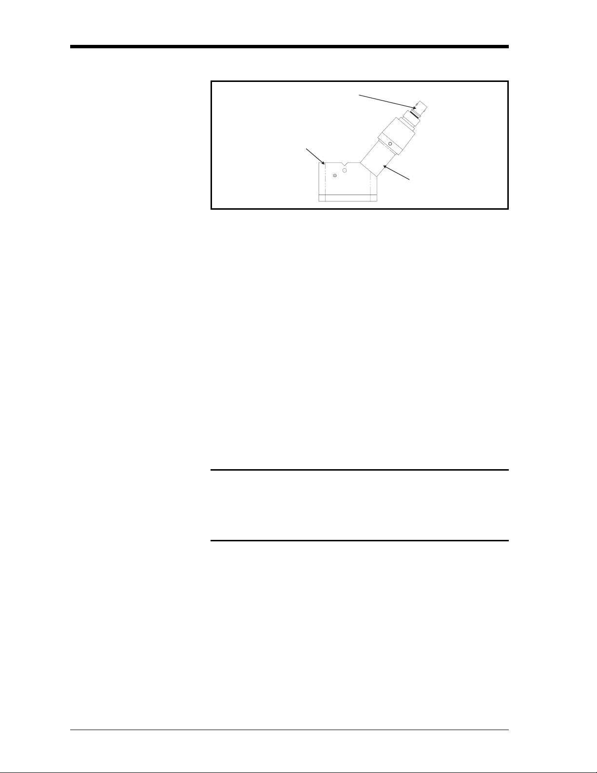
Each transducer assembly consists of the following components (see
Figure 1-1 on the next page):
F (-40 to 90oC)*.
• a stainless steel adapter with 3/4” NPT male thread for
attaching a junction box
• a transducer that consists of a piezoelectric element mounted on
a wedge and wired to the connector
• a connector for use in connecting the transducer to the
flowmeter.
*This temperature is for ATEX certified designs. Consult factory for
higher temperatures.
Installation 1-1
Page 11
July 2006
ISXDR Transducers
(cont.)
Transducer Body
Figure 1-1: ISXDR Transducer Components
Connector
Adapter
Unpacking Carefully remove the electronics enclosure and the transducer/cable
assembly from the shipping containers. Before discarding any of the
packing materials, account for all components and documentation
listed on the packing slip. The discarding of an important item along
with the packing materials is all too common. If anything is missing
or damaged, contact the factory immediately for assistance.
Site Considerations Because the relative location of the transducers and the electronics
enclosure is important, use the guidelines in this section to plan the
ISX878 installation.
Electronics Enclosure Location
The standard ISX878 electronics enclosure is epoxy-coated
aluminum rated for weatherproof NEMA T ype 4X, IP67 applications.
Typically, the enclosure is mounted as close as possible to the
transducers. When choosing a site, make sure the location permits
easy access to the electronics enclosure for programming,
maintenance and service.
Transducer Location Caution!
The Model ISX878’s accuracy and performance depends
primarily on the location, spacing and alignment of the
transducers. The transducer spacing is unique to your
installation.
In addition to accessibility, when planning for transducer location,
adhere to the following procedure:
1. Locate the transducer measurement point at least 3 ft (1 m) or
more from any butt welds or flanges, ideally in the center of a
20 ft (6 m) length of straight run of pipe. Keep appropriate
clearance on either side of the pipe for easy transducer installation:
• 6 in. (15 cm) if you are not using a junction box, or
• 9 in. (22.5 cm) if you are using a junction box.
1-2 Installation
Page 12
July 2006
Transducer Location
(cont.)
Note: To guarantee the specified accuracy of the flowmeter there is
no substitute for a straight run pipe and fully-developed flow
profile. However, if straight run is not available, the
transducer location should be in a position such that the
acoustic signal travels through the full distribution of the
under-developed flow profile for best repeatability.
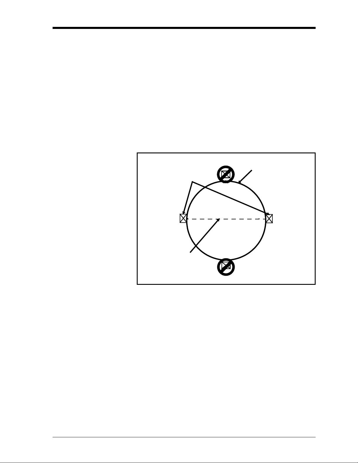
2. Place the transducers as close as possible to the horizontal plane.
(see Figure 1-2 below). Locate the transducers on opposite sides
o
of the pipe 180
apart, ideally at the 3 and 9 o’clock positions. Do
not place transducers on the top or bottom of the pipe.
Note: For best profile identification in limited straight run, place
transducers at 1 and 7 o’clock.
Pipe
Transducer
Signal Path
End View
Figure 1-2: Transducer Placement
Cable Lengths Locate the electronics enclosure as close as possible to the
transducers. GE Sensing can supply ISX878 transducer cables in
fixed lengths up to 100 ft (30 m) in length for remote location of the
electronics enclosure.
Transducer Cables When installing the transducer cables, always observe established
standard practices for the installation of electrical cables. Do not route
transducer cables alongside high amperage AC power lines or any
other cables that could cause electrical interference. Also, protect the
transducer cables and connections from the weather and corrosive
atmospheres. Do not run the transducer cables along a pipe with a
surface temperature over 75°C (167°F) for models ISXDR-407 and
ISXDR-408.
IMPORTANT: Use only the cables and transducers that have been
supplied with the ISX878.
Installation 1-3
Page 13

July 2006
Mounting the ISX878 Electronics Enclosure
Making the Electrical Connections
The standard Model ISX878 electronics package is housed in a
epoxy-coated aluminum weatherproof NEMA4X, IP67 enclosure
suitable for indoor or outdoor use. Figure 1-27 on page 1-29 shows
the outline and installation drawing. Refer to Chapter 7,
Specifications, for the mounting dimensions and the weight of this
enclosure.
This section contains instructions for making all the necessary
electrical connections to the Model ISX878 flow transmitter . Refer to
Figure 1-31 on page 1-33 for a complete wiring diagram.
!ATTENTION EUROPEAN CUSTOMERS!
To meet CE Mark requirements, all cables
must be installed as described in
Appendix B, CE Mark Compliance.
!WARNING!
Always disconnect the input power from the Model ISX878
before removing the front cover.
Preparing the Unit Before
Making Electrical
Prepare the unit as described below before making any electrical
connections.
Connections
1. Disconnect any previously wired power line from the unit.
2. Remove the screws on the front cover.
3. Install any required cable clamps on the appropriate conduit holes
on the bottom of the enclosure.
Proceed to the next section to make the desired wiring connections.
Intrinsic Safety The ISX878 flowmeter is listed as “Intrinsically Safe” for hazardous
locations. “Intrinsically Safe” means that the circuits within this
flowmeter are designed to be incapable of producing a spark or
thermal effect that could ignite a mixture of flammable or
combustible gases when properly installed in a hazardous location.
However, it does not mean that the ISX878 is “Explosion-Proof.” If
proper safety precautions are not followed, or if the equipment is not
installed properly, there is a serious potential for possible explosion.
Be sure to review all safety precaution, installation, and wiring
directions throughout this manual prior to installing the ISX878
flowmeter. The ISX878 provides intrinsically safe outputs to the
transducers, allowing the transducers to be located in a hazardous
(Classified) location. The ISX878 electronics can be mounted in a
hazardous (classified) location when appropriate safety barriers are
used. See “Safety Barriers” on the next page.
1-4 Installation
Page 14

July 2006
Intrinsically Safe Installation Requirements
Where possible, mount the associated apparatus in a non-hazardous
location as near as possible to the hazardous location. This will
minimize the length of intrinsically safe conductors within the nonhazardous location, thus decreasing the possibility of inadvertent
connection of non-intrinsically safe energy to the protected circuit.
!WARNING!
Intrinsically safe wiring must be separated from non-
intrinsically safe wiring to prevent the transfer of unsafe
levels of energy to the hazardous area. Consult local codes
and authorities having jurisdiction over the area.
Safety Barriers The Model ISX878 requires the use of a safety barrier(s). Refer to
Table 1-1 below for the required safety barrier specifications for use
with the Model ISX878.
Note: Safety barriers must be installed in accordance with the
barrier manufacturer’s specifications.
Table 1-1: Safety Barrier Specifications
Loop Power
Totalizer
Output
Alarm Switch
Output
MTL-7706 or
equivalent
Umax 28 VDC 28 VDC 10 VDC
Imax 93 mA 93 mA 19 mA
Rmax 300 ohm 300 ohm
Pmax 0.6 5 W 0.65 W 0.19 W
MTL-7787 or
equivalent
MTL-7741 or
equivalent
Installation 1-5
Page 15

July 2006
Wiring the Input Power Note: If the input voltage needs to be adjusted, select “Voltage
Adjust” from the Service Menu and press [ENT]. Then adjust
the input voltage and press [ESC]. This procedure allows the
meter to correctly read the input voltage to adjust the power
management algorithm.
Refer to Figure 1-31 on page 1-33 to locate the power terminal block
and connect the input power as follows:
1. Follow the instructions on page 1-4 to prepare the unit before you
connect power.
!ATTENTION EUROPEAN CUSTOMERS!
To meet CE Mark requirements, all cables
must be installed as described in
Appendix B, CE Mark Compliance.
2. Connect the ISX878 case to the earth ground with a grounding
cable to the external ground screw found on either side of the
enclosure.
3. Strip 1/4-in. of insulation from the end of each of the two input
power leads.
4. Route the shielded cable through the conduit hole and connect the
power leads to the power terminal block as shown in Figure 1-31
on page 1-33. Tie the shield drain wire to the ground bus bar inside
the ISX878, but leave the shield wire open on the power supply
end (to avoid AC ground loops and for CE certification).
5. Leaving a small amount of slack, secure the power line with the
cable clamp.
6. Connect the two power leads to the safety barrier, as shown in
Figure 1-3 on the next page. Barriers must be installed in
accordance with the barrier manufacturer’s specifications.
1-6 Installation
Page 16
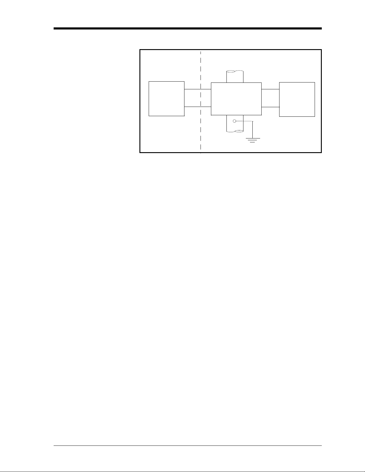
Wiring the Input Power
(cont.)
Hazardous
Location
July 2006
Non-Hazardous Location
(Safe Area)
Determining the Number of Traverses
(+)
(-)
I.S. Ground
ISX878
1(+)
TB3
2(-)
Approved
Safety
Barrier
(See Note)
Figure 1-3: Power Lead Connection to Safety Barrier
7. If you are installing the ISX878 for the first time, refer to Chapter
2, Programming Site Data, and program the sections from page 24 to 2-14 (the Status, Transducer , Pip e, Fluid and Path options) to
determine the appropriate transducer spacing to position the
transducers (see page 1-9).
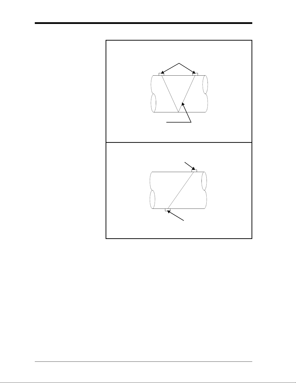
The next step in installation is to determine the number of traverses.
The transducers can be mounted using one of two methods (shown in
Figure 1-4 on the next page:
• Double-traverse method (“V” method) - transducers are mounted
on the same side of the pipe and the ultrasonic signal is bounced
from one transducer to the other, off the opposite pipe wall.
• Single-traverse method (“Z” method) - transducers are mounted
diagonally across from each other. The ultrasonic signal is
transmitted directly from one transducer to the other, across the
pipe.
You should always try the double-traverse method first, since it easier
to install and yields greater accuracy. Otherwise, the single-traverse
method is best for pipes with the following:
• poor inside surface conditions
• highly attenuating fluid
Note: You may want to try both configurations to see which yields
more accurate results.
Installation 1-7
Page 17
July 2006
Determining the Number
of Traverses (cont.)
Double Traverse (“V” Method)
Transducers
Ultrasonic Signal Path
Single Traverse (“Z” Method)
Transducer
Transducer
Figure 1-4: Double- and Single-Traverse Installations
TOP VIEW
TOP VIEW
1-8 Installation
Page 18
July 2006
Installing the Transducers
Small Pipe Transducer Installation
The transducers that have been specially designed for use with the
ISX878 are available in four models: 4 MHz for 1/2 to 2 in. pipes; 2
MHz for 1/2 to 8 in.; 1 MHz for 2 to 16 in.; and 500 kHz for 6 to 16
in. They typically support 2-traverse applications. Two styles of
transducer are available; one style, intended for smaller pipes,
integrates the cable and clamping fixture, while the other style
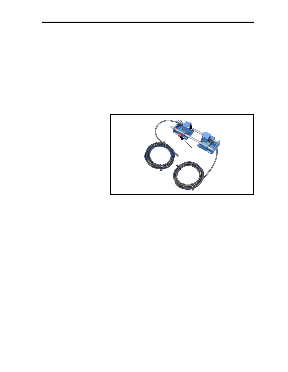
accommodates larger pipes. The preattached cables come in lengths
from 6 to 25 ft. (Longer lengths are available by special order. Please
consult the factory.) Figure 1-5 below shows a typical ISX878
transducer, while the outline and installation drawing for the
clamping fixture appears in Figure 1-30 on page 1-32.
Adjustment
Screws
Setting Transducer
Spacing
Figure 1-5: ISX878 Transducer/Cable Assembly
Note: If the calculated spacing exceeds the minimum allowed by the
transducers, set the transducers to minimum spacing, and
override the calculated value to the values measured on the
transducers
If you have not already obtained the transducer spacing, you must
program the Status, Transducer, Pipe, Fluid and Path options of the
Program menu (pages 2-4 to 2-14) to calculate the appropriate
setting. To set the desired transducer spacing:
1. Loosen the red screws on the adjustable transducer (shown in
Figure 1-5 above).
2. Slide the adjustable transducer on the rails until you have
positioned it at the desired spacing. Use the ruler on the rails and
the white tick mark on the transducer housing to assist in setting
the correct spacing.
3. Tighten the red screws to secure the transducer to the rails.
Installation 1-9
Page 19
July 2006
Setting Transducer
Spacing (cont.)
Installing the Transducers
on the Pipe
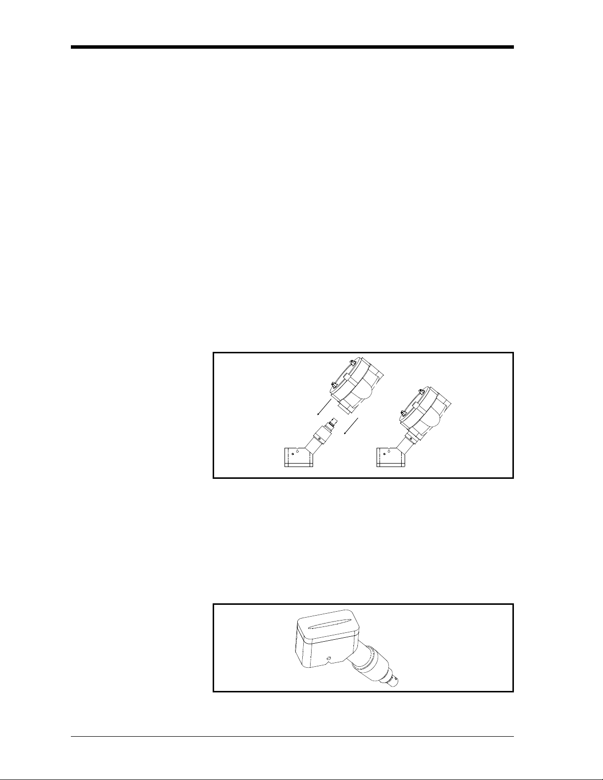
Note: If your application requires one or three traverses, you can
remove the adjustable transducer fr om the rails and use it as a
separate transducer at a 180° angle from the stationary
transducer, as shown in Figure 1-6 below.
Figure 1-6: Positioning for 1 or 3-Traverse Applications
Note: Some pipe preparation may be required before securing the
transducers to the pipe. Remove any paint or coating from the
surface in contact with the transducers. A flat, smooth surface
is ideal.
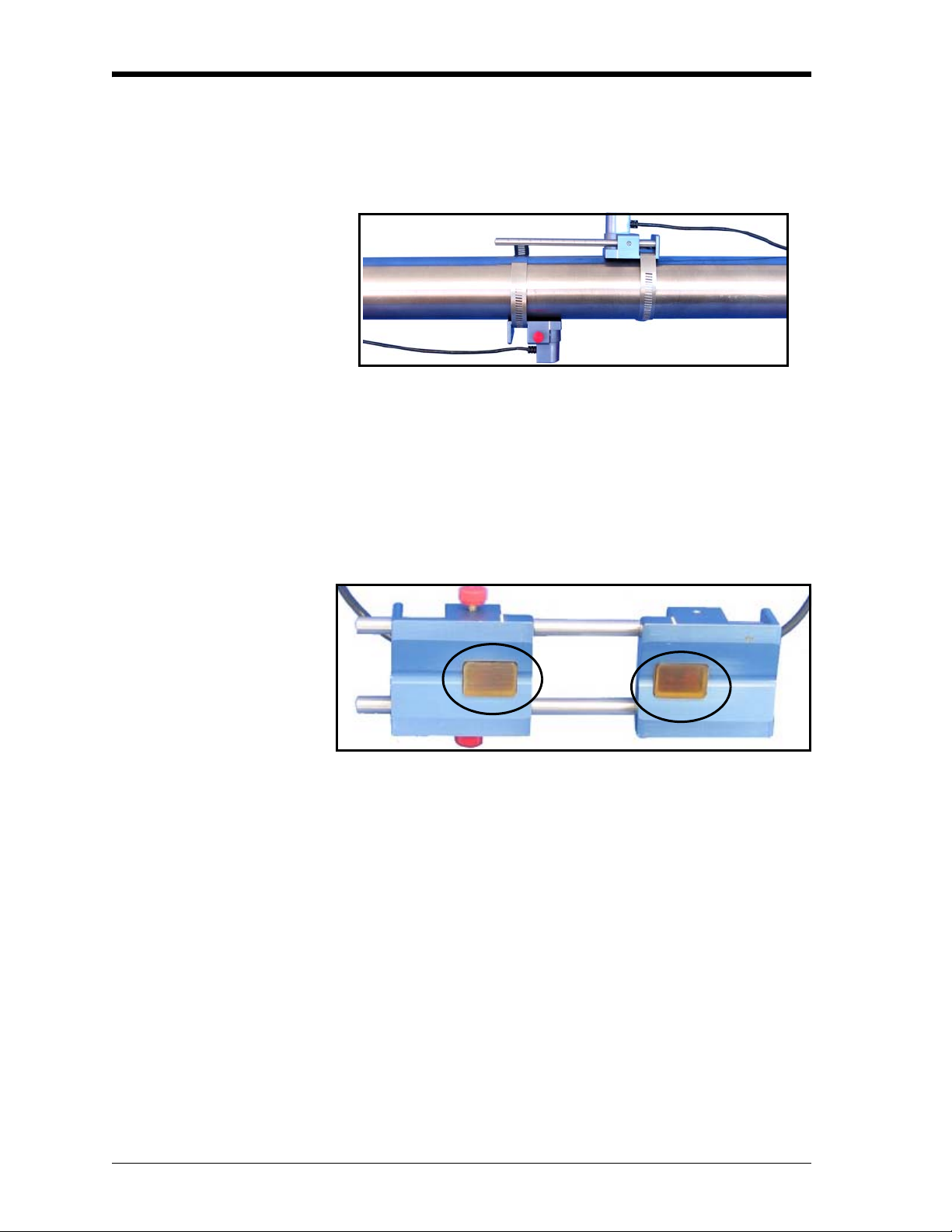
1. Apply the supplied couplant to the transducer faces, as shown in
Figure 1-7 below.
Figure 1-7: The Transducer Faces
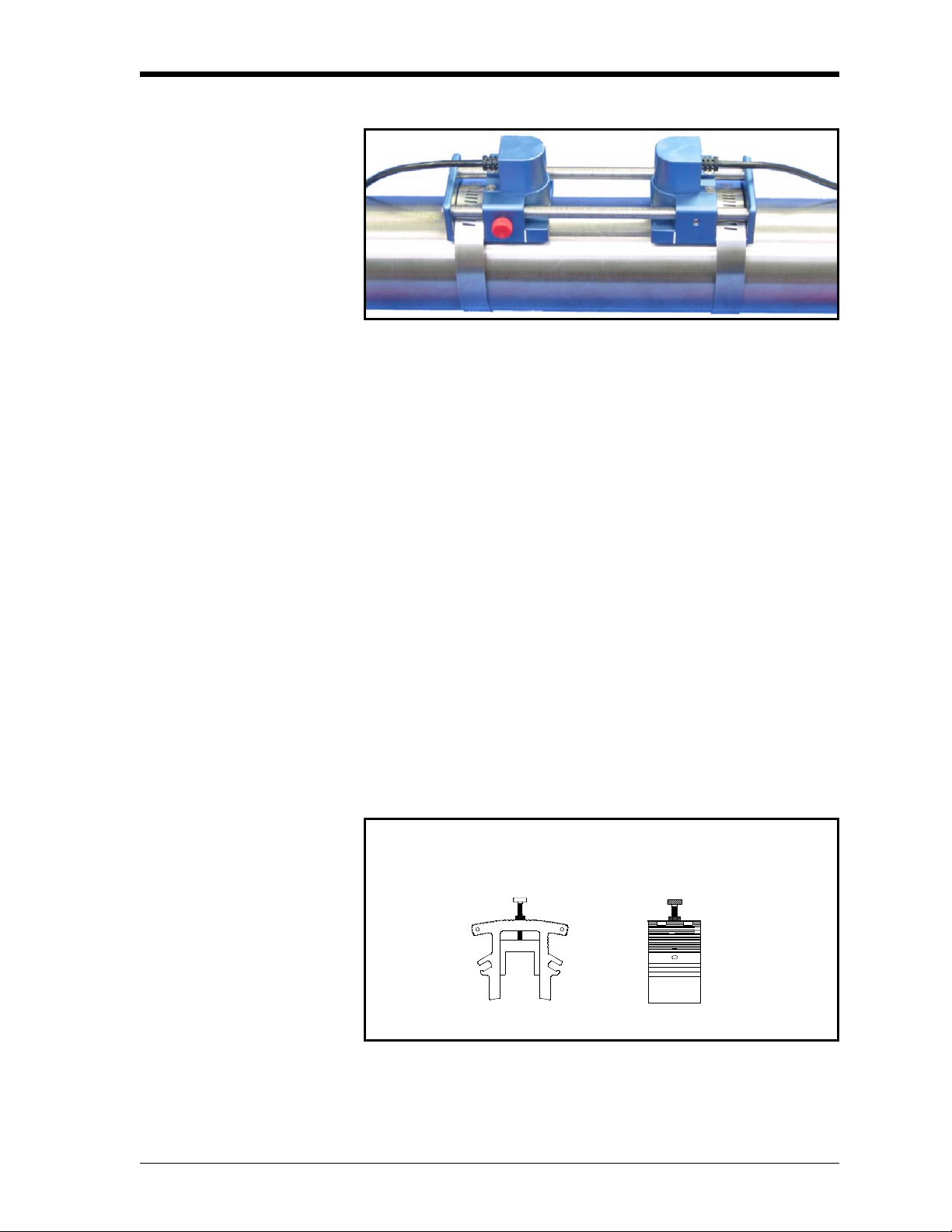
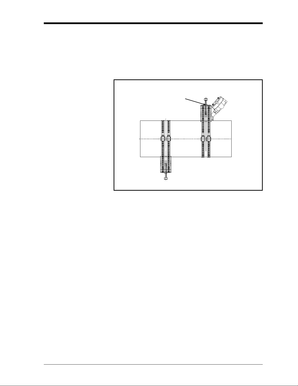
2. Put the transducer fixture at the desired location on the pipe.
Secure it with the supplied stainless steel clamps. Figure 1-8 on
the next page illustrates a typical installation.
Note: Installation on the sides (at 3 and 9 o’clock) of the pipe is
ideal. The top of the pipe might contain bubbles, while the
bottom might contain sediment.
1-10 Installation
Page 20
Installing the Transducers
on the Pipe
July 2006
Figure 1-8: A Typical Transducer Installation
Once on the pipe, an internal spring mechanism ensures proper
mechanical pressure by “pressing” the transducer face against the
pipe surface. Refer to the next page to wire the transducer cables to
the ISX878.
Large Pipe Fixture and Transducer Installation
The CF-ES clamping fixture acts as a permanent transducer holder.
The fixture has two blocks that are used for double- and singletraverse methods. Steel straps secure the blocks to the pipe for a
permanent installation.
The blocks are positioned properly using the spacing dimension
calculated by the flowmeter. Then the transducers are mounted into
the blocks. Figure 1-9 below shows a long block.
The transducer installation consists of mounting the CF-ES to the
pipe and then mounting the transducers into the blocks. Refer to the
appropriate section that follows for instructions:
• Double-traverse Method - see the next page
• Single-traverse Method - see page 1-16.
End View
Side View
Figure 1-9: CF-ES Clamping Fixture Block
Installation 1-11
Page 21
July 2006
The Double-Traverse
Method - CF-ES
Note: The instructions in this section can also be used for a
multiple-traverse method. However, you must use an EVEN
number of traverses. The distance the signal travels from one
side of the pipe wall to the opposite side of the pipe wall is
considered one traverse. For more than two traverses, consult
the factory.
There are three advantages in using the double-traverse method:
• Accuracy is improved because the signal is in the fluid longer than
with a single-traverse.
• This configuration can reduce some effects of an underdeveloped
flow profile.
• If there is enough pipe length available, the double-traverse fixture
is easier to install.
The procedure for mounting the CF-ES involves marking the pipe for
the desired spacing, fastening the clamping fixture on the pipe and
then mounting the transducers into the fixture.
Procedure:
You will need a level and a marker or scribe to locate and mark the
transducer locations on the pipe.
1. Obtain the transducer spacing dimension S.
2. Be sure the location you have chosen for the installation has at
least 10 pipe diameters of straight, undisturbed flow upstream and
5 pipe diameters downstream of the measurement point.
3. Prepare the pipe where you intend to place the clamping fixture by
making sure it is clean and free of loose material. Sanding, though
usually not required, may be necessary to take off any high spots.
Be careful to preserve the original curvature of the pipe.
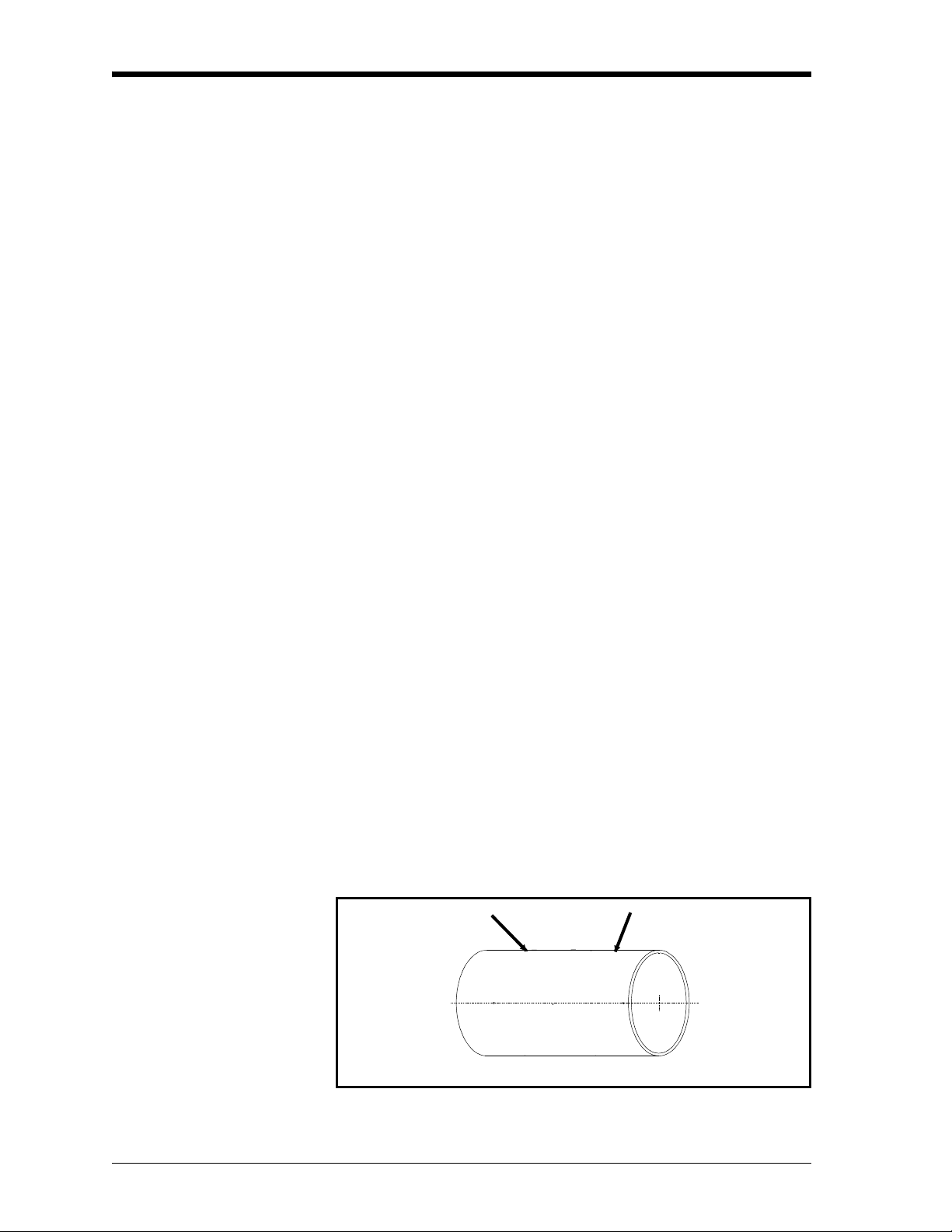
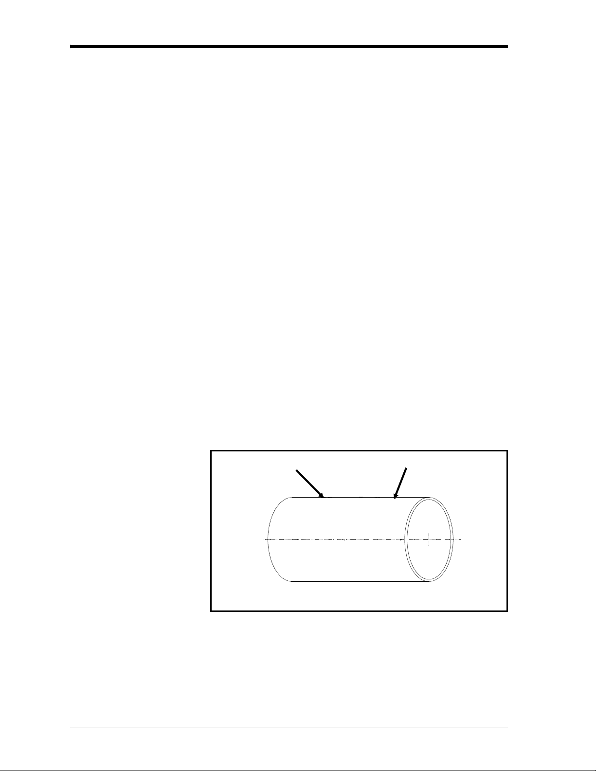
4. Find the top of the pipe and use a level to draw a line parallel to
the pipe’s axis, as shown in Figure 1-10 below.
Line
Top of Pipe
Side View
Figure 1-10: Line Parallel to Pipe Axis
1-12 Installation
Page 22
July 2006
The Double-Traverse
Method - CF-ES (cont.)
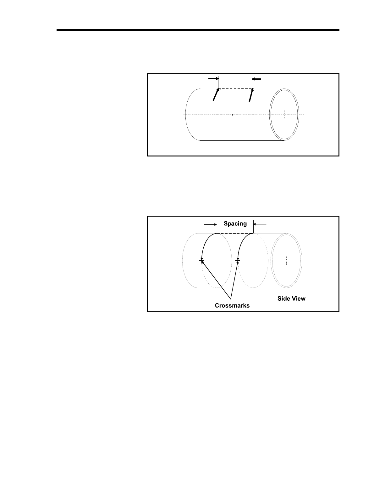
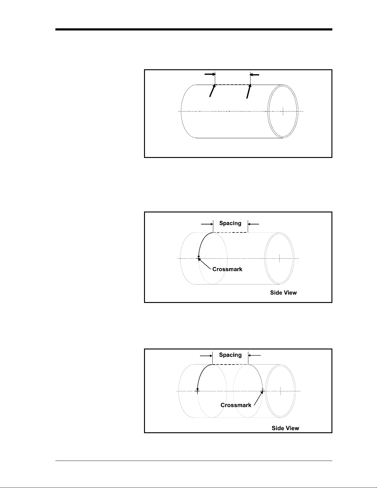
5. Make two marks (shown in Figure 1- 1 1 below) on the line equal to
the transducer spacing distance S, as calculated by the meter.
Spacing
Mark
Mark
Side View
Figure 1-11: Marks for Transducer Spacing on Inscribed Line
6. From each of the m a rks , m e as u r e a round the circumference of the
pipe in the same direction a distance equal to one quarter the
pipe’s circumference, as shown in Figure 1-12 below. Make a
crossmark with a marker or scribe.
Figure 1-12: Measuring a Quarter-Circumference
Installation 1-13
Page 23
July 2006
The Double-Traverse
Method - CF-ES (cont.)
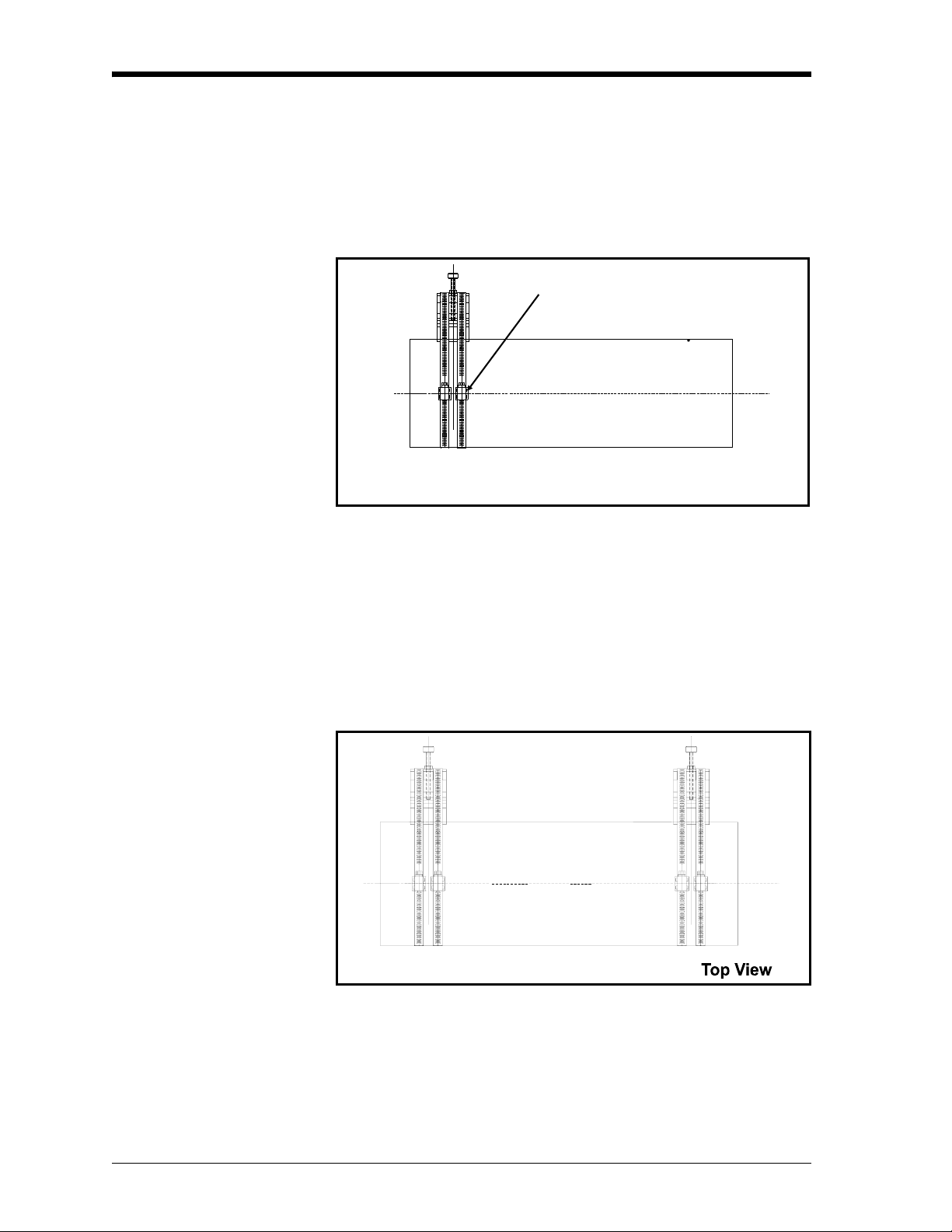
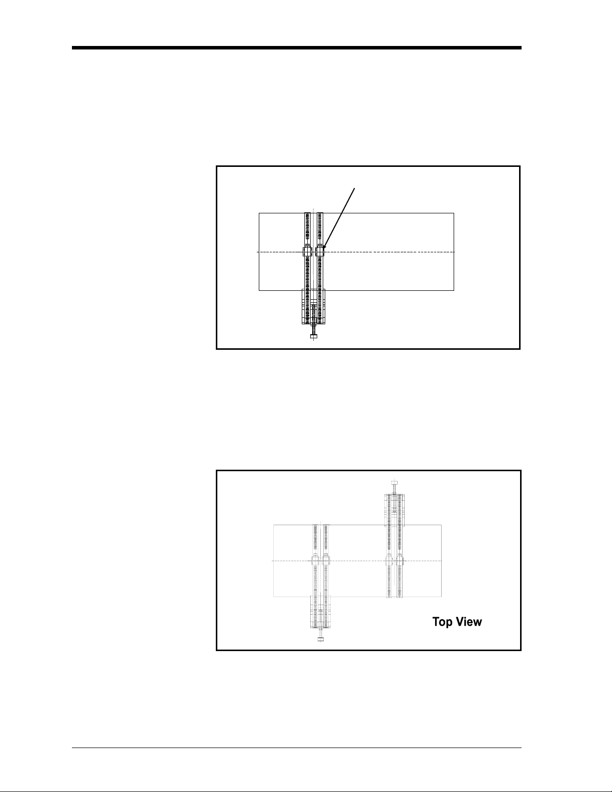
7. Center one of the blocks over one of the crossmarks on the pipe.
Align the block so that the pressure bolt is over the center of the
mark. Secure the block by wrapping the two straps around the
block and pipe and tightening them. Make sure the turnbuckles are
at least 1/2 pipe diameter away from the block, as shown in Figure
1-13 below.
Turnbuckles
Top View
Figure 1-13: Positioning Turnbuckles 1/2 Pipe Diameter
from Block
8. Repeat Step 7 to install the other block over the other crossmark
(Figure 1-14 below).
Note: Make sure both straps are perpendicular to the bottom of the
block. If the straps are slanted, the slack will cause the block
to slide. The slack may also change the transducer spacing
after the transducers are mounted.
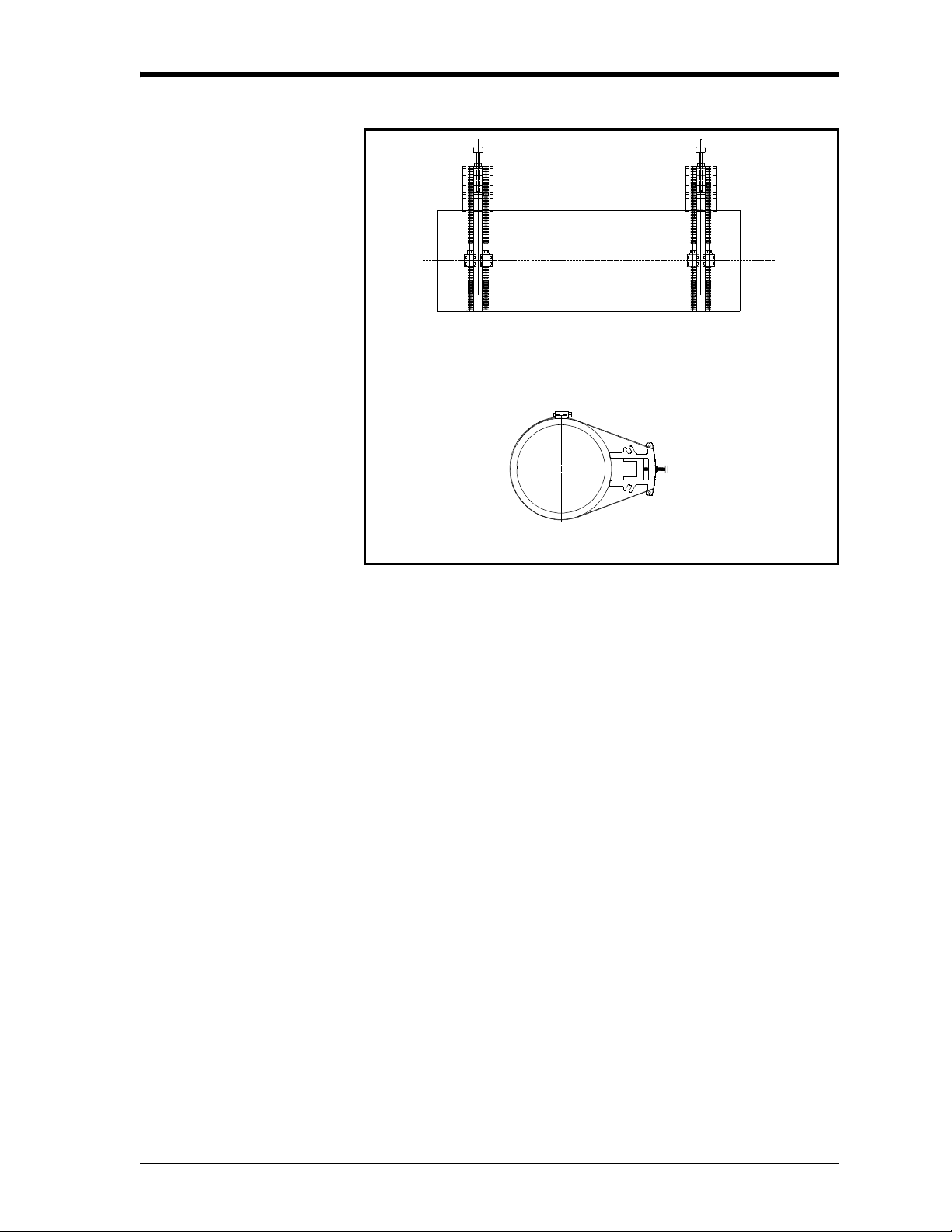
Figure 1-14: Positioning Both Blocks
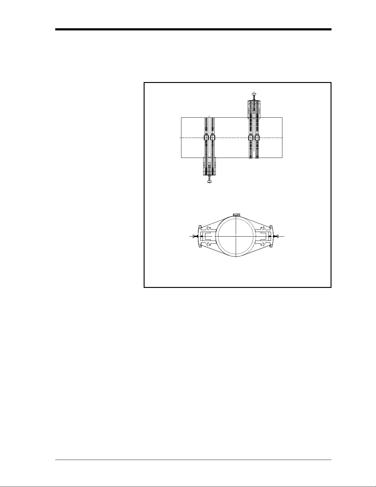
Figure 1-15 on the next page shows a double-traverse installation
without transducers. Proceed to Mounting Transducers into the CF-
on page 1-20.
ES
1-14 Installation
Page 24
The Double-Traverse
Method - CF-ES (cont.)
July 2006
Top View
End View
Figure 1-15: A Double-Traverse CF-ES Installation without
Transducers
Installation 1-15
Page 25
July 2006
The Single-Traverse
Method - CF-ES
Note: The instructions in this section can also be used for a
multiple-traverse method. However, you must use an ODD
number of traverses. The distance the signal travels from one
side of the pipe wall to the opposite side of the pipe wall is
considered one traverse.
The procedure for mounting the CF-ES involves marking the pipe for
the desired spacing, fastening the fixture to the pipe and then
mounting the transducers into the fixture.
Procedure:
You will need a level and marker or scribe to locate the transducers on
the pipe.
1. Obtain the transducer spacing dimension S, as described on pages
2-4 to 2-14.
2. Be sure the location you have chosen for the installation has at
least 10 pipe diameters of straight, undisturbed flow upstream and
5 pipe diameters downstream of the measurement point.
3. Prepare the pipe where you intend to place the CF-ES by making
sure it is clean and free of loose material. Sanding, though usually
not required, may be necessary to take off any high spots. Be
careful to preserve the original curvature of the pipe and not to
eradicate the marks on the pipe.
4. Find the top of the pipe and use a level to draw a line parallel to
the pipe’s axis, as shown in Figure 1-16 below.
Line
Top of Pipe
Side View
Figure 1-16: Drawing Line Parallel to Pipe Axis
1-16 Installation
Page 26
July 2006
The Single-Traverse
Method - CF-ES (cont.)
5. Make two marks (shown in Figure 1-17 below) on the line equal to
the transducer spacing distance S, as calculated by the meter.
Spacing
Mark
Mark
Side View
Figure 1-17: Marking Transducer Spacing
6. From one of the marks, measure around the circumference of the
pipe a distance equal to one quarter the pipe’s circumference, as
shown in Figure 1-18 below. Make a crossmark with a marker or
scribe.
Figure 1-18: Measuring a Quarter of the Pipe’s Circumference
7. From the other mark, go in the opposite direction around the pipe
for one quarter the circumference and make another crossmark, as
shown in Figure 1-19 below.
Figure 1-19: Measuring the Second Quarter Circumference
Installation 1-17
Page 27
July 2006
The Single-Traverse
Method — CF-ES (cont.)
8. Center one of the blocks over one of the crossmarks on the pipe.
Align the block so that the pressure bolt is over the center of the
crossmark. Secure the block by wrapping two straps around the
block and pipe and tightening them. Make sure the turnbuckles are
at least 1/2 pipe diameter away from the block, as shown in Figure
1-20 below.
Turnbuckles
Top View
Figure 1-20: Positioning Turnbuckles
9. Repeat Step 8 to install the other block over the other punch mark.
Note: Make sure both straps are perpendicular to the bottom of the
block (Figure 1-21 below). If the straps are slanted, the slack
will cause the block to slide. The slack may also change the
transducer spacing after the transducers are mounted.
Figure 1-21: Correct Strap Positioning
1-18 Installation
Page 28
July 2006
The Single-Traverse
Method -CF-ES (cont.)
Figure 1-22 below shows a single-traverse installation without
transducers. Proceed to Mounting Transducers into the CF-ES
next page.
Top View
on the
End View
Figure 1-22: A Single-Traverse CF-ES Installation without
Transducers
Installation 1-19
Page 29
July 2006
Mounting Transducers into the CF-ES
The last step of installation is mounting the transducers into the
clamping fixture.
IMPORTANT: To maintain ATEX certification, the transducer face
must be protected again st impact. This is provided by
properly installing the transducer into the clamping
fixture. All care must be taken during installation to
ensure all protection is afforded.
Procedure for Mounting Transducers
To mount the transducers into the CF-ES, use the following steps:
1. Apply a thread sealant to the transducer threads. A sealant is not
required within the US; however, a sealant must be used in the
European Community .
2. Before mounting the transducers, thread the junction box onto the
end of the transducer with the connector, as shown in Figure 1-23
below. Ensure that at least five full threads are engaged. Make sure
to orient the cover of the junction box so it is accessible to make
cable connections once the box is installed.
Figure 1-23: Threading the Junction Box
3. Take one of the transducers and apply a thin bead of couplant
down the center of its face approximately the size of a toothpaste
bead (Figure 1-24 below).
IMPORTANT: To prevent the loss of couplant, do not slide the
transducer with couplant along the surface of the
pipe when mounting.
Figure 1-24: Applying Couplant to Transducer
1-20 Installation
Page 30
July 2006
Mounting Transducers
into the CF-ES (cont.)
4. Place the transducers in the appropriate blocks. Make sure the
transducers are oriented as shown in Figure 1-25 below.
Note: If the transducer cables are already connected, you must
determine the upstream and downstr eam directions of the pipe
and place the transducers into the appropriate blocks.
Locking Nut
Top View
Figure 1-25: Transducer Orientation
5. Use the pressure bolt to secure the transducer in place. The
pressure bolt should fit into the dimple. Hand-tighten enough to
hold the transducer in place. Do not overtighten so that the
fixture lifts off the pipe.
6. Tighten the locking nut on the pressure bolt (see above).
IMPORTANT: When using the CF-ES in a pipe location with
possible mechanical vibration, the locking nut must
be used to secure the position of the pressure bolt on
the transducer after the bolt has been hand-tightened
into the transducer dimple. For additional resistance
to vibration a thread lock compound or a stainless
steel washer and lock washer may also be used.
These items can be ordered from GE by requesting a
“special” clamping fixture and specifying either the
thread lock or the washers.
7. Repeat Steps 1 to 6 to mount the other transducer in the
remaining block. See Figure 1-26 on the next page for completed
installations.
Installation 1-21
Page 31

July 2006
Mounting Transducers into
the CF-ES (cont.)
!WARNING!
Before performing the next step make
sure power to the flowmeter electronics
has been disconnected.
8. Make transducer ca ble connections as described on the next
page.
Double-Traverse Installation (Top View)
Single-Traverse Installation (Top View)
Figure 1-26: Completed CF-ES Installations with Transducers
Note: If you have mounted the transducers into the CF-ES properly,
the two transducer cable connectors will face away from each
other as shown in the above figure.
1-22 Installation
Page 32

July 2006
Wiring the Transducers Follow the instructions on page 1-4 before wiring the transducers.
!WARNING!
Before connecting the transducers, discharge any static
buildup by shorting the twisted pairs of the transducer
cables to the metal shield on the cable connector.
1. Refer to the wiring diagram in Figure 1-31 on page 1-33 and
connect the transducer cables to the terminal block (TB-1) for
Channel 1. Then, secure the cable clamp.
Note: The RED (or BLUE) cable leads are the SIG (+) leads and the
BLACK (or BROWN) cable leads are the RTN (-) leads. The
shield cable leads are connected to the ground bus.
!ATTENTION EUROPEAN CUSTOMERS!
To meet CE Mark requirements, all cables
must be installed as described in
Appendix B, CE Mark Compliance.
2. For a 2-path averaging ISX878, repeat step 1 to connect the CH2
transducers to the terminal block for Channel 2. It is not
that both channels/paths of a 2-Channel unit be connected.
Note: The ISX878 uses two channels or paths to make more accurate
flow measurement by averaging, subtracting or adding the
channels/paths together.
3. Connect the transducer shield wires to the ISX878 ground bus.
4. Do one of the following:
required
• Proceed to the next page to wire the ISX878 option cards, if
desired.
• Proceed to page 1-26 to wire the ISX878 RS232 serial port, if
desired.
• Replace the front cover on the enclosure and tighten the screws.
!WARNING!
Use RS232 connections only in the safe area.
Note: A channel must be activated before it can begin taking
measurements. See Chapter 2, Programming Site Data, for
instructions.
Installation 1-23
Page 33

July 2006
Wiring the Option Cards Follow the instructions on page 1-4 before wiring the option cards.
Wiring the Totalizer Option Refer to Figure 1-31 on page 1-33 to locate the totalizer terminal
block and connect the totalizer option card as follows:
1. Follow the instructions on page 1-4 to prepare the unit before you
connect power.
!ATTENTION EUROPEAN CUSTOMERS!
To meet CE Mark requirements, all cables
must be installed as described in
Appendix B, CE Mark Compliance.
2. Connect the ISX878 case to the earth ground with a grounding
cable.
3. Strip 1/4-in. of insulation from the end of each of the two option
card leads.
4. Route the shielded cable through the conduit hole and connect the
totalizer card to the totalizer card terminal block as shown in
Figure 1-31 on page 1-33. Tie the shield drain wire to the ground
bus bar inside the ISX878, but leave the shield wire open on the
power supply end (to avoid AC ground loops and for CE
certification).
5. Leaving a small amount of slack, secure the totalizer option card
line with the cable clamp.
6. Connect the two totalizer option cards leads to the safety barrier.
Barriers must be installed in accordance with the barrier
manufacturer’s specifications.
1-24 Installation
Page 34

July 2006
Wiring the Alarm Switch
Option
Refer to Figure 1-31 on page 1-33 to locate the alarm terminal block
and connect the alarm option card as follows:
1. Follow the instructions on page 1-4 to prepare the unit before you
connect the card.
!ATTENTION EUROPEAN CUSTOMERS!
To meet CE Mark requirements, all cables
must be installed as described in
Appendix B, CE Mark Compliance.
2. Connect the ISX878 case to the earth ground with a grounding
cable.
3. Strip 1/4-in. of insulation from the end of each of the two option
card leads.
4. Route the shielded cable through the conduit hole and connect the
alarm card to the alarm card terminal block as shown in Figure 131 on page 1-33. Tie the shield drain wire to the ground bus bar
inside the ISX878 to the closest grounding screw, but leave the
shield wire open on the other power supply end (to avoid AC
ground loops and for CE certification).
5. Leaving a small amount of slack, secure the totalizer alarm switch
output option card line with the cable clamp.
6. Connect the two totalizer alarm switch output option cards leads to
the safety barrier. Barriers must be installed in accordance with the
barrier manufacturer’s specifications.
Installation 1-25
Page 35

July 2006
Wiring the RS232 Serial Port
!WARNING!
Use RS232 connections only in the safe area.
The Model ISX878 flow transmitter is equipped with a built-in
RS232 serial communications port. Proceed to the section below for
wiring instructions. For more information on serial communications,
refer to the EIA-RS Serial Communications manual (916-054).
Use the serial port to connect the Model ISX878 flow transmitter to
an ANSI terminal or a personal computer. The RS232 interface is
wired as Data Terminal Equipment (DTE), and the signals available
at the COMMUNICATION terminal block are shown in Table 1-1
below.
1. Follow the instructions on page 1-4 to prepare the unit before you
connect power.
2. Use the information in Table 1-2 below to construct a suitable
shielded cable for connecting the Model ISX878 to the external
device. If desired, an appropriate cable may be purchased from GE
Sensing.
Note: The DTR and RTS signals power the ISX878 communication
circuit and are required for proper operation. Consult the
factory if you have additional questions.
Communication
TB4
1 White DTR 20 4 20 4
2 Yellow RTS 4 7 4 7
3 Green Signal Ground 7 5 7 5
4 Black ISX878 (Transmit) 2 3 3 2
5 Red ISX878 (Receive) 3 2 2 3
Note: Signal names that imply direction (e.g., transmit and receive)
are named from the point of view of the DTE device (the GE
Sensing meter is usually considered the DTE device).
When the RS232 standard is strictly followed, these signals
are labeled with the same name and pin # on the DCE device
side as well. Unfortunately, the convention is not followed
because the DTE and DCE side get confused. Therefore,
connections that imply direction are changed to reflect their
direction on the DCE side.
Table 1-2: RS232 Connection to DCE or DTE Device
DCE
Colors for GE
Cable 704-845 Signal Description
DB25
Pin #
DCE
DB9
Pin #
DTE
DB25
Pin #
DTE
DB9
Pin #
1-26 Installation
Page 36

July 2006
Wiring the RS232 Serial
Port (cont.)
3. Feed the flying leads end of the cable through the conduit hole and
wire the leads to the COMMUNICATION terminal block (TB4) as
shown in Figure 1-31 on page 1-33. Connect the other end of the
cable to the ANSI terminal or personal computer, and secure the
cable clamp.
4. Tie the shield drain wire to the ISX878 ground bus bar.
!ATTENTION EUROPEAN CUSTOMERS!
To meet CE Mark requirements, all cables
must be installed as described in
Appendix B, CE Mark Compliance.
After the wiring has been completed, replace the front cover on the
enclosure and tighten the screws. Consult the user’s manual for the
external device to configure it for use with the ISX878.
Service Requirements In the event of equipment malfunction, all repairs should be
performed by an authorized agent. It is the responsibility of users
requiring service to contact the factory for repair or service:
GE Industrial Sensing
1100 Technology Park Dr.,
Billerica, MA 01821 USA
Telephone: (978) 437-1000 or
Toll-free: (800) 833-9438
http://gesensing.com/contact/contactus.htm
What’s Next? After the ISX878 has been completely installed and wired, reconnect
input power.
• Check the diagnostics (discussed in Chapter 6, Error Codes and
Diagnostics) to ensure that the ISX878 has been properly set
up.
• Refer to Chapter 2, Programming Site Data, to program the
meter for taking flow rate measurements.
Installation 1-27
Page 37

July 2006
GND LUG
2X
NOTES:
1. ALL DIMENSIONS ARE REFERENCE.
2. ALL DIMENSIONS IN INCHES [MM].
LOW PROFILE
Figure 1-27: ISX878 Outline and Installation (Dwg. #712-1195, rev. 2)
Installation 1-29
Page 38

July 2006
Installation 1-30
Figure 1-28: Two-Traverse Installation (Dwg. 570-095, sh. 1)
Page 39

July 2006
Installation 1-31
Figure 1-29: Single-Traverse Installation (Dwg. 570-095, sh. 2)
Page 40

July 2006
Installation 1-32
Figure 1-30: Clamping Fixture Outline and Installation (Dwg. #570-076, rev. 1)
Page 41

July 2006
Installation 1-33
Figure 1-31: ISX878 Wiring Diagram (Dwg. #702-528, rev. 4)
Page 42

Chapter 2
Page 43

Programming Site Data
Introduction. . . . . . . . . . . . . . . . . . . . . . . . . . . . . . . . . . . . . . . . . . . . . . . . . . . . 2-1
Activating a Channel/Path (Status) . . . . . . . . . . . . . . . . . . . . . . . . . . . . . . . 2-4
Entering Transducer Parameters . . . . . . . . . . . . . . . . . . . . . . . . . . . . . . . . . 2-6
Entering Pipe Parameters . . . . . . . . . . . . . . . . . . . . . . . . . . . . . . . . . . . . . . . 2-8
Entering Fluid Data . . . . . . . . . . . . . . . . . . . . . . . . . . . . . . . . . . . . . . . . . . . . 2-12
Entering Path Data . . . . . . . . . . . . . . . . . . . . . . . . . . . . . . . . . . . . . . . . . . . . 2-15
Entering Signal Parameters. . . . . . . . . . . . . . . . . . . . . . . . . . . . . . . . . . . . . 2-16
Entering the Meter Correction (K) Factor . . . . . . . . . . . . . . . . . . . . . . . . . 2-18
Entering Error Limits . . . . . . . . . . . . . . . . . . . . . . . . . . . . . . . . . . . . . . . . . . . 2-19
What’s Next? . . . . . . . . . . . . . . . . . . . . . . . . . . . . . . . . . . . . . . . . . . . . . . . . . .2-20
Page 44

July 2006
Introduction The Model ISX878 flow transmitter includes a User Program that
provides access to the various programmable features of the
instrument.This chapter describes step-by-step programming
instructions using the internal keypad, shown below in Figure 2-1.
W
W
W
W
ENT
Ch1 Volumetric
100.00
Gallons/min E0
Figure 2-1: An ISX878 Display and Keypad
Refer to the appropriate section for a discussion of the following
PROG menu options:
ESC
• Status - activate or deactivate one or both channels/paths
Note: The ISX878 can use two channels or paths to make more
accurate flow measurement by averaging, subtracting or
adding the channels/paths together.
• Transducer - enter data for preprogrammed or special clamp-on
transducers
• Pipe - enter pipe parameters
• Fluid - enter fluid type and Reynolds Correction data
• Path - enter number of traverses and transducer spacing (for
clamp-on transducers)
• Signal - entering signal parameters such as Delta-T offset, zero
cutoff and velocity averaging
• K Factor - entering the Meter Correction (K) Factor as a single
value or as a table of values
• Error Limits - entering minimum and maximum signal, velocity,
amplitude and soundspeed.
To measure flow rate with the ISX878 you must, at a minimum,
activate the channel/path(s), and enter transducer, pipe and fluid
parameters. As a programming aid, Appendix A includes a complete
set of menu maps for the user program, and Figure A-1 on page A-1
offers the menu map for the PROG menu.
Note: This manual will describe only the programming of Channel
1. To program Channel 2 of a 2-channel/path meter, simply
repeat the same procedures presented for Channel 1.
Programming Site Data 2-1
Page 45

July 2006
Unlocking and Locking the ISX878
T o prevent unauthorized tampering with either the display or the user
program, the ISX878 offers a pair of security codes. Once you have
set the security level, an operator requires one of these codes to
change either the display (Prog Lock) or the display and the user
program (Full Lock).
Note: To speed up the key response of the ISX878, deactivate CH1
(and CH2), as described on page 2-4. Remember to reactivate
the channels when programming is complete.
Unlocking the ISX878 To unlock the display and/or the user program:
1. Press
[ESC], [ENT], [ESC]. A Security Check window, similar to
Figure 2-2 below, opens.
Security Check
ENTER VALUE
9999
[ENT] = save changes
[ESC] = undo changes
[W] [X] = move cursor
[S] [T] = change value
Figure 2-2: Security Check Window
2. Using the arrow keys, change the code number to the value
desired for your security level.
• For Prog Lock (granting access only to the display), the number
2719.
is
• For Full Lock (granting access to the display and user
program), the number is
3. Press [ENT]. The display screen reappears, with the lock removed
or partially unlocked. Security will remain at this level until you
change the level in the user program, as described on the next
page.
7378.
2-2 Programming Site Data
Page 46

Locking the ISX878 You can access the security level in two ways.
From the display screen:
1. Press the [X] key three times, until the lock in the upper right
corner is highlighted.
July 2006
2. Press
From the User Program:
1. Press
2. Press the [X] key until USER is bracketed.
3. The menu highlights Set Security. Press
4. The screen shows three options:
[ENT], and proceed to step 4 below.
[ESC]. The ISX878 enters the User Program.
[ENT].
• Full Lock, which prevents a user from changing any part of the
display or user program without the appropriate code:
• Prog Lock, which allows a user to change the display but not to
enter the user program:
• Unlocked, which allows access to both the display and the user
program.
Scroll to the desired option and press
5. Press
[ESC] to return to the User Program, or continue pressing
[ESC] to return to the display screen. If you have chosen to fully
lock the ISX878, the screen appears similar to Figure 2-3 below,
with a solid lock in the upper right corner. (For a meter with only
the user program locked, the lock shows a keyhole in the center.)
[ENT] twice.
Ch 1 Velocity
0.0
Meters/sec E1
Figure 2-3: ISX878 Screen with Locked Program
Programming Site Data 2-3
Page 47

July 2006
Activating a Channel/ Path (Status)
In the Status submenu of the PROG menu, you can activate or
deactivate a channel/path. While the channel/path should be activated
when you receive your unit, you should verify that the channel/path is
active before you begin programming. When following the
programming instructions, refer to Figure A-1 on page A-1 of
Appendix A, Menu Maps. Remember to record all programmed data
in Appendix C, Data Records.
Note: If you are not using Channel 2 of a two-channel ISX878,
disable it to increase the response time.
To access the Status submenu:
1. Press
[ESC]. The ISX878 enters the User Program.
2. Press the [X] key until PROG is bracketed in the top left corner
and press
[ENT].
3. Use the [S] and [T] keys to scroll to the desired channel and
[ENT]. The screen appears similar to Figure 2-4 below.
press
PROG PROG/PROG
St a tus. . .
Transducer . . .
Pipe . . .
Fluid . . .
Path . . .
Signal . . .
T
K Factor . . .
Figure 2-4: The PROG Menu
4. Press
[ENT] to open the Status submenu.
5. The screen offers two options, ON and OFF. Use the [S] and [T]
keys to scroll to the desired selection and press
[ENT].
IMPORTANT: On any menu, if you scroll to a differ ent option, press
[ENT] twice to select that option (once to enter and
again to confirm the selection).
6. Press
[ESC] (or [ENT] twice if you have selected the other option) to
return to the channel menu.
2-4 Programming Site Data
Page 48

July 2006
What’s Next?
After completing the above steps, the user program returns to the
PROG menu. Do one of the following:
• To enter transducer data, press the [T] key to highlight the
Transducer listing and press
[ENT].
• To program in other menus, refer to Appendix A, Menu Maps, to
navigate to the desired menu.
• To leave the User Program, press [ESC] three times.
Programming Site Data 2-5
Page 49

July 2006
Entering Transducer Parameters
The Transducer submenu enables you to enter parameters for
preprogrammed or special clamp-on transducers. Remember to
record all programmed data in Appendix C, Data Records.
Note: If you have programmed the Status submenu, proceed directly
to Step 4. If you scr oll to a differ e nt option, pr ess
[ENT] twice to
select that option (once to enter and again to confirm the
selection).
To access the Transducer submenu:
1. Press
2. Press the [X] key until
[ESC]. The ISX878 enters the User Program.
PROG is bracketed in the top left corner and
[ENT].
press
3. Use the [S] and [T] keys to scroll to the desired Channel and
[ENT].
press
4. Scroll to the Transducer submenu and press
[ENT].
5. Scroll to Clamp-on and press [ENT].
6. Scroll to either Preprogrammed (for the standard transducers) or
Other (for special transducers), and press
[ENT].
7. The program also asks for the Wedge Temperat u re . Scroll to the
Wedge TMP option and press
keys to enter the temperature, and press
[ENT]. Then use the [S] and [T]
[ENT].
Note: The wedge temperature of the transducer can be
approximated by inputting an average value for the surface
temperature of the outside pipe wall.
8. Do one of the following:
• For preprogrammed transducers, scroll to the desired
Transducer Number (either 407 (2 MHz), 408 (4 MHz), 409
(500 kHz) or 410 (1 MHz)) and press
[ENT]. Then press [ESC]
three times to return to the PROG menu.
• For other transducers, proceed to Other Transducers on the
next page.
IMPORTANT: Other (special) transducers have no engraved
number on the housing and are rarely used. Examine
the transducer housing carefully for a number.
2-6 Programming Site Data
Page 50

July 2006
Other Transducers 1. The first required parameter is the Frequency. Press [ENT] to open
the Frequency window. Then scroll to the frequency of your
transducer (from 0.25 to 4.00 MHz) and press
2. The meter next asks for the Time Delay (Tw). Scroll to the Tw
option and press
[ENT]. Then use the arrow keys to enter the time
provided by GE Sensing (in microseconds), and press
3. The next parameter is the Wedge Angle, the angle of the
transducer’s ultrasonic transmission in the transducer wedge.
Scroll to the W e dge Ang option and press
to enter the provided angle (in degrees), and press
4. To enter the Wedge Soundspeed, scroll to the Wedge SS option an d
[ENT]. Use the arrow keys to enter the provided soundspeed
press
(in m/s or ft/s), and press
[ENT].
5. The final parameter is the Temperature Coefficient. Scroll to the
TempCo option and press
provided coefficient, and press
[ENT]. Use the arrow keys to enter the
[ENT]. Set the coefficient to 0 if you
are unsure of the value.
[ENT].
[ENT].
[ENT]. Use the arrow keys
[ENT].
You have completed entering parameters for other transducers. Press
[ESC] until you reach the PROG menu to continue programming, or
continue pressing
[ESC] to resume displaying data.
Programming Site Data 2-7
Page 51

July 2006
Entering Pipe Parameters
In the Pipe submenu, you can specify preprogrammed or special pipe
parameters. While following the programming instructions, refer to
Figure A-1 on page A-1 of Appendix A, Menu Maps. Remember to
record all programmed data in Appendix C, Data Records.
Note: If you are in the
scroll to a different option, press
PROG menu, proceed dir ectly to Step 4. If you
[ENT] twice to select that
option (once to enter and again to confirm the selection).
To access the Pipe submenu:
1. Press
2. Press the [X] key until
[ESC]. The ISX878 enters the User Program.
PROG is bracketed and press [ENT].
3. Use the [S] and [T] keys to scroll to the desired Channel and
[ENT].
press
4. Scroll to the Pipe submenu and press [ENT].
Entering the Pipe Material 1. The menu offers two options, Material and Lining. Be sure the
Material option is highlighted, and press
2. Two other options now appear, Preprogrammed and Other. Scroll
to the desired option, and press
[ENT].
[ENT].
3. The menu now varies with your choice in Step 2.
• For preprogrammed materials, a list of materials opens. Table 2-1
on the next page covers the available preprogrammed materials on
the list. Press the [
material. Press
T] or [S] keys to scroll to the appropriate
[ENT] to confirm the choice.
• For other materials, the meter asks for the material Soundspeed.
[ENT] to open the window. Then use the arrow keys to enter
Press
the known soundspeed, and press
[ENT].
2-8 Programming Site Data
Page 52

July 2006
Entering the Pipe Material
(cont.)
.
Table 2-1: Preprogrammed Pipe Materials
Pipe Material Category Specific Material
Al - Aluminum Rolled or None
Brass None
Cu - Copper Annealed, Rolled or None
CuNi - Copper/Nickel 70% Cu 30% Ni or 90% Cu 10% Ni
Glass Pyrex, Flint, or Crown
Gold Hard-drawn
Inconel None
Iron Armco, Ductile, Cast, Electrolytic
Monel None
Nickel None
Plastic Nylon, Polyethylene, Polypropylene,
PVC (CPVC), or Acrylic
Steel Carbon Steel, Mild or Stainless Steel
Tin Rolled
Titanium None
Tungsten Annealed, Carbide, Drawn
Zinc Rolled
4. The next required parameter is either the outside diameter (OD) or
the circumference (OD x
press
[ENT]. For either measurement, enter the desired value and
[ENT].
press
π). Scroll to the measured parameter and
Note: Obtain the required information by measuring either the pipe
outside diameter (OD) or circumference at the transducer
installation site. The data may also be obtained fr om standard
pipe size tables found in Sound Speeds and Pipe Size Data
(914-004).
5. The meter also requires the Wall Thickness (WT). Scroll to the WT
option, and press
thickness, and press
[ENT]. Use the arrow keys to enter the known
[ENT].
Note: To obtain an accurate pipe wall thickness measurement, use
an ultrasonic thickness gauge.
Programming Site Data 2-9
Page 53

July 2006
Entering the Pipe Material
(cont.)
6. If you have selected certain materials (such as carbon or stainless
steel, cast iron, PVC and CPVC), the ISX878 offers the option of
entering the pipe dimensions by a standardized schedule. (This
option does not appear unless you have selected one of these
materials; if you have, proceed to step a below.) Once you enter
the nominal pipe size and schedule number, the ISX878
determines the OD and wall thickness from an internal table.
a. Scroll to the Schedule option, and press
[ENT].
b. A list of pipe sizes opens, from 15 to 200 mm (0.5 to 8 in.).
Scroll to the desired pipe size, and press
[ENT].
c. A list of schedules opens. Scroll to the desired schedule, and
[ENT].
press
You have finished entering the pipe parameters. Press
return to the Pipe Material/Lining window , or continue pressing
[ESC] until you
[ESC]
to return to the data display window.
2-10 Programming Site Data
Page 54

Entering Pipe Lining Data To access the Lining option:
1. From the Pipe submenu, scroll to the Lining option, and press
[ENT].
2. Two options appear, Material and Thickness. Be sure Material is
highlighted, and press
3. Two other options now appear, Preprogrammed and Other. Scroll
to the desired option, and press
4. The menu now varies with your choice in Step 3.
[ENT].
• For preprogrammed linings, the screen shows a list of Lining
Materials, listed in Table 2-2 below. Scroll to the appropriate
material. If the pipe has no lining, select “None.” Press
confirm the choice.
• For other materials, the next screen asks for the lining Soundspeed.
[ENT] to open the soundspeed window. Use the arrow keys to
Press
enter the known soundspeed, and press
July 2006
[ENT].
[ENT] to
[ENT].
Table 2-2: Preprogrammed Lining Materials
Lining Material Options
None
Tar/Epoxy
Glass (Pyrex)
Asbestos Cement
Mortar
Rubber
PTFE
Note: If your pipe lining is not on the drop-down list, consult GE
Sensing for further information.
What’s Next? You have finished entering data in the Pipe submenu. Do one of the
following:
• To program in other options, press [ESC] until you return to the
PROG menu.
• To program in other menus, refer to Appendix A, Menu Maps, to
navigate to the desired menu.
• To leave the User Program, press [ESC] until the display screen
reappears.
Programming Site Data 2-11
Page 55

July 2006
Entering Fluid Data The Fluid submenu allows you to specify the fluid you are measuring,
as well as the Reynolds Correction factor and tracking windows.
While following the programming instructions, refer to Figure A-1 on
page A-1 of Appendix A, Menu Maps. Remember to record all
programmed data in Appendix C, Data Records.
Note: If you are in the
scroll to a different option, press
PROG menu, proceed dir ectly to Step 4. If you
[ENT] twice to select that
option (once to enter and again to confirm the selection).
To access the Fluid submenu:
1. Press
2. Press the [X] key until
[ESC]. The ISX878 enters the User Program.
PROG is bracketed in the top left corner and
[ENT].
press
3. Use the [S] and [T] keys to scroll to the desired Channel and
[ENT].
press
4. Scroll to the Fluid submenu and press [ENT].
Entering Fluid Type 5. Two options appear, Fluid Type and Reynolds. Scroll to Fluid T ype
and press
6. Two other options appear, Normal and Tracking. Tracking refers
to Tracking Windows, which are used to detect the receive signal
when you are unsure of the fluid sound speed, or when the fluid
sound speed changes drastically under process conditions. Scroll
to the desired option and press
7. You can now select between Preprogrammed and Other fluids.
Scroll to the desired option, and press
[ENT].
[ENT].
[ENT].
• For Normal fluids, you can program the expected fluid
Temperature. Scroll to the Temperature option and press
Then use the arrow keys to enter the process temperature, and
press
[ENT].
[ENT].
• For fluids monitored with a T r acking Window, the meter offers
the selections of Water (up to either 100 or 260°C) or Oil. Scroll
to the desired listing and press
2-12 Programming Site Data
[ENT].
Page 56

July 2006
Entering Fluid Data
(cont.)
8. The menu now varies, depending on your selections in steps 6
and 7.
• If you have selected Preprogrammed fluids, the ISX878 supplies a
list of preprogrammed fluids. As shown in T able 2-3 below, the list
varies, depending on whether you have selected normal or tracki ng
window fluid types. In either case, scroll to the desired fluid and
[ENT].
press
• If you selected Other, the ISX878 asks for the fluid soundspeed
(for Normal fluids) or minimum and maximum soundspeed (for
Tracking Window fluids). In either case, scroll to the soundspeed
option and press
soundspeed, and press
Tracking Windows Off Tracking Windows On
Water (0-260°C) Water (0-100°C)
Sea Water Water (0-260°C)
Oil (22°C) Oil
Crude Oil
[ENT]. Use the arrow keys to enter the appropriate
[ENT].
Table 2-3: Preprogrammed Fluid Types
Entering Reynolds Correction Data
Lube Oil (X200)
Methanol (20°C)
Ethanol
LN2 (-199°C)
Freon (R-12)
Diesel
Gasoline
9. Press the [ESC] key until you return to the Fluid Type window
discussed in Step 5.
Reynolds Correction is a correction factor based on the Kinematic
Viscosity and flow rate of the fluid. It is necessary, as the velocity of
the fluid measured along a diametrical path must be related to the
total area average velocity over the entire pipe cross-section. This
factor should be ON in most applications, including all those that use
clamp-on transducers. To access Reynolds Correction data:
1. From the Fluid Type window (described in step 5 on the previous
page), scroll to Reynolds and press
[ENT].
2. The screen shows three options: Off, Single and Table. Scroll to
the desired option, and press
Programming Site Data 2-13
[ENT].
Page 57

July 2006
Entering Reynolds
Correction Data (cont.)
3. The menu varies, depending on your selection in Step 2.
• If you select Off, no further choices are available.
• If you select Single, the ISX878 will select and automatically
display the Kinematic Viscosity. To change the value, press
Use the arrow keys to change the value (available in document
#914-004, Sound Speeds and Pipe Size Data), and press
[ENT].
[ENT].
• If you select Table, the screen displays three options: Units, Rows
Used and Edit Table.
a. If you scroll to Units and press
more options: Velocity, Soundspeed and Diagnostic. If you
select either Velocity or Soundspeed and press
displays the measurement units (either metric or English).
[ESC] or [ENT] to return to the previous screen. But if you
Press
scroll to Diagnostic and press
of signal to be used, Signal Strength Up or Signal Strength Dn.
Scroll to the appropriate signal, and press
b. If you select Rows Used, the program asks for the number of
rows you wish to use. Enter the desired number (from 2 to 20)
and press
[ENT].
[ENT], the screen displays three
[ENT], the screen
[ENT], the meter asks for the type
[ENT].
c. If you select Edit Table, the table opens with a series of rows.
Scroll to the desired row, and press
[ENT].
d. For each row, the screen displays the Reynolds Correction
number (X) and the Kinematic Viscosity (KV). If you wish to
change either value, scroll to the value and press
[ENT]. Use the
arrow keys to change the value (available in document #914004, Sound Speeds and Pipe Size Data), and press
[ENT].
e. Repeat steps c and d until you have programmed all of your
available data (from 2 to 20 rows).
[ESC] until you return to the PROG menu, or continue pressing
Press
[ESC] until the display screen reappears.
2-14 Programming Site Data
Page 58

July 2006
Entering Path Data In the Path submenu, you can specify and check the path taken by the
transducer signal. Remember to record all programmed data in
Appendix C, Data Records.
Note: If you are in the PROG menu, proceed directly to Step 4. If you
scroll to a different option, press
option (once to enter and again to confirm the selection).
To access the Path submenu:
[ENT] twice to select that
1. Press
2. Press the [X] key until PROG is bracketed and press
[ESC]. The ISX878 enters the User Program.
[ENT].
3. Use the [S] and [T] keys to scroll to the desired Channel and
[ENT].
press
4. Scroll to the Path submenu and press [ENT].
5. The meter first asks for the number of Traverses, or times the
signal crosses the pipe. Press
traverses for your installation, and press
[ENT], scroll to the number of
[ENT] to confirm the entry.
Note: The great majority of ISX applications call for two traverses.
Figure 2-5 below illustrates signal paths for a typical twotraverse installation.
Figure 2-5: Signal Paths for a Two-Traverse Installation
6. The remaining prompt displays the Transducer Spacing, as
calculated from the information entered. Use this number to set
the spacing of the transducers. (The minimum spacing is 0.9 in.)
If necessary, you can overwrite the spacing to match the actual
physical spacing of the transducers. Press
[ENT] to open the
Spacing window, and use the arrow keys to change the value.
Then press
[ENT] to confirm the value.
IMPORTANT: It is recommended that you do not use a spacing
other than the one calculated by the ISX878.
However, if yo u do use a different spacing, do not
change the spacing by more than ±10% from that
calculated by the ISX878.
[ESC] until you return to the PROG menu, or continue pressing
Press
[ESC] until the display screen reappears.
Programming Site Data 2-15
Page 59

July 2006
Entering Signal Parameters
In the Signal submenu, you can set parameters that affect the
transducer signal:
Caution!
The SIGNAL default settings are suitable for most
applications. Consult GE Sensing before changing any of
these applications.
• Delta-T Offset
• Zero Cutoff
• Errors Allowed
• Peak Detection Method and Thresholds
• Transmit Sample Size
• Velocity Averaging
While following the programming instructions, refer to Figure A-1 on
page A-1 of Appendix A, Menu Maps.
Note: If you are in the PROG menu, proceed directly to Step 4. If you
scroll to a different option, press
option (once to enter and again to confirm the selection).
[ENT] twice to select that
To enter the Signal submenu:
1. Press
2. Press the [X] key until PROG is bracketed and press
3. Use the [S] and [T] keys to scroll to the desired Channel and
4. Scroll to the Signal option and press [ENT].
5. The first prompt, Delta-T Offset, is the difference between the
6. The next prompt asks for the Zero Cutoff. Near “zero” flow, the
[ESC]. The ISX878 enters the User Program.
[ENT].
[ENT].
press
upstream and downstream transit times of the transducer signals.
It should normally be set to 0. Press
enter the new value, and press
ISX878 may have fluctuating readings due to small offsets
(caused by factors such as thermal drift in the fluid). The zero
cutoff causes velocity measurements less than the cutoff to be
reported as zero. To set the cutoff, press
keys to enter the new value. Press
[ENT], use the arrow keys to
[ENT] to confirm your entry.
[ENT], and use the arrow
[ENT] to confirm your entry.
2-16 Programming Site Data
Page 60

July 2006
Entering Signal
Parameters (cont.)
7. The Errors Allowed prompt specifies the number of errors the
ISX878 can record before displaying an error message. Press
[ENT], and use the [S] and [T] keys to scroll to the appropriate
number of errors (from 0 to 16). Press
[ENT] to confirm your entry.
8. The next prompt asks for the Peak Detection method. In the
“Peak” method, the peak is identified by testing a derivative of the
signal. In the “Threshold” method, the peak is identified as the
point where the signal crosses a threshold that is a percentage of
the maximum signal detected. The peak method is more reliable in
identifying the signal in dynamic conditions, while the threshold
method is more reliable in marginal signal conditions.
Note: Do not change the peak detection method or values unless
recommended by GE Sensing.
a. Press
[ENT]. The screen shows the two display options, Peak
and Threshold. Scroll to the desired option, and press
[ENT].
b. The next screen depends on your selection in Step a.
• If you select Peak, no further options are available. Press [ESC]
to return to the Signal menu.
• If you select Threshold and press [ENT], the screen shows three
parameters: Min Threshold, Max Threshold and Percent of
Peak. For each parameter, press
enter the new value, and press
[ENT]. Use the arrow keys to
[ENT].
9. The next parameter is the Transmit Sample Size, the number of
pulses each transducer (upstream and downstream) emits. It is set
to 8 by default. Press
to the new number (from 1 to 32). Press
[ENT], and use the [S] and [T] keys to scroll
[ENT] to confirm the entry.
10.The final prompt asks for V elocity A veraging, in which users select
a certain number of velocity measurements to average together to
smooth out noise in the signal. Press
[ENT], and use the [S] and
[T] keys to scroll to the desired number . (Selections include none,
2, 5, 10, 30, 60 and Statistics. The Statistics option increases
averaging under steady flow conditions, but allows for a rapid
response to step changes in flow rate.) Press
[ENT] to confirm your
entry.
You have completed entering parameters in the Signal option. Press
[ESC] until you return to the PROG menu, or continue pressing [ESC]
until the display screen reappears.
Programming Site Data 2-17
Page 61

July 2006
Entering the Meter Correction (K) Factor
With the K Factor submenu, you can calibrate or adjust the ISX878
readings to another flow reference. While following the programming
instructions, refer to Figure A-1 on page A-1 of Appendix A, Menu
Maps.To enter K Factor data:
Note: If you are in the
scroll to a different option, press
PROG menu, proceed dir ectly to Step 4. If you
[ENT] twice to select that
option (once to enter and again to confirm the selection).
1. Press
2. Press the [X] key until
[ESC]. The ISX878 enters the User Program.
PROG is bracketed in the top left corner and
[ENT].
press
3. Use the [S] and [T] keys to scroll to the desired Channel and
[ENT].
press
4. Scroll to the K Factor submenu and press
[ENT].
5. The screen shows three options: Off, Single and Table. Scroll to
the desired option, and press
[ENT].
6. The menu varies, depending on your selection in Step 5.
• If you select Off, no further choices are available.
• If you select Single, the ISX878 displays the K Factor. To change
the value, press
[ENT].
press
[ENT]. Use the arrow keys to change the value and
IMPORTANT: If you have enabled the Reynolds Correction factor
in the Fluid option, the K factor should be set to 1.00.
Otherwise, the typical factor is between 0.5 and 2.00.
• If you select Table, the screen displays three options: Units, Rows
Used and Edit Table.
a. If you scroll to Units and press
selected measurement units (either metric or English). Press
[ESC] or [ENT] to return to the previous screen.
b. If you select Rows Used, the program asks for the number of
rows you wish to use. Enter the desired number (from 2 to 20)
and press
[ENT].
c. If you select Edit Table, the table opens with a series of rows.
Scroll to the desired row, and press
d. For each row, the screen displays the X (velocity) value and the
K Factor. If you wish to change either value, scroll to the value
and press
press
[ENT]. Use the arrow keys to change the value and
[ENT].
e. Repeat steps c and d until you have programmed all available
data (from 2 to 20 rows).
[ESC] until you return to the PROG menu, or continue pressing
Press
[ESC] until the display screen reappears.
[ENT], the screen displays the
[ENT].
2-18 Programming Site Data
Page 62

July 2006
Entering Error Limits The Error Limits option enables you to set limits for an incoming
signal. When the signal falls outside the programmed limits, an error
indication appears on the display screen. To set error limits, follow
the steps below.
Note: If you are in the
scroll to a different option, press
PROG menu, proceed directly to Step 4. If you
[ENT] twice to select that
option (once to enter and again to confirm the selection).
1. Press
2. Press the [X] key until
[ESC]. The ISX878 enters the User Program.
PROG is bracketed in the upper left corner
and press
[ENT].
3. Use the [S] and [T] keys to scroll to the desired Channel and
press
[ENT].
4. Scroll to the Error Limits option and press [ENT].
5. The first prompt asks for the Minimum Signal limit for the
transducer signal received by the ISX878. The E1:LOW SIGNAL
error message appears if the signal strength falls below the limit
programmed here. Press
value and press
[ENT].
[ENT]. Use the arrow keys to change the
6. Repeat the steps above for the Maximum Signal limit.
7. The next prompt calls for the Minimum Velocity limit. Press
Use the arrow keys to change the value and press
[ENT].
[ENT].
8. Repeat the steps above to change the Maximum Velocity limit.
(The E3: VELOCITY RANGE error message appears if the
velocity falls outside the minimum and maximum limits.)
9. The meter now asks for the Min Amplitude, the lower limit for the
amplitude discriminator. The discriminator measures the size of
the transducer signal sent from the ISX878. If the signal falls
outside these limits, the E5: AMPLITUDE error message appears.
[ENT]. Use the arrow keys to change the value and press
Press
[ENT].
10.Repeat these steps for the Max Amplitude, the upper limit for the
discriminator.
11.The next prompt asks for the acceptable limits for the sound
speed, based on conditions in your particular system. The E2:
SOUND SPEED error message appears if the fluid sound speed
exceeds that entered in the Fluid submenu by more than this
percentage. Press
percentage and press
[ENT]. Use the arrow keys to change the
[ENT].
Programming Site Data 2-19
Page 63

July 2006
Entering Error Limits
(cont.)
12.The final prompt asks for the acceleration limit for detecting cycle
skipping. The E6: ACCELERATION error message appears if the
velocity changes by more than this limit from one reading to the
next. Press
[ENT].
[ENT]. Use the arrow keys to change the value and press
What’s Next? You have finished entering data in the PROG menu. Do one of the
following:
• To program in other menus, refer to Appendix A, Menu Maps, to
navigate to the desired menu.
• To return to the display screen, press [ESC] until the display screen
reappears.
• To configure the display, proceed to the next chapter.
2-20 Programming Site Data
Page 64

Chapter 3
Page 65

Displaying Data
Introduction. . . . . . . . . . . . . . . . . . . . . . . . . . . . . . . . . . . . . . . . . . . . . . . . . . . . 3-1
Setting Up the Display. . . . . . . . . . . . . . . . . . . . . . . . . . . . . . . . . . . . . . . . . . . 3-1
Setting Screen Contrast . . . . . . . . . . . . . . . . . . . . . . . . . . . . . . . . . . . . . . . . . 3-5
Setting the Number of Screen Views . . . . . . . . . . . . . . . . . . . . . . . . . . . . . . 3-5
Page 66

July 2006
Introduction The Model ISX878 flow transmitter includes a Liquid Crystal
Display (LCD) that can display up to two variables simultaneously.
Users can change the number of variables, the displayed
measurements and units, and the contrast level of the LCD.
Setting Up the Display You can configure either of two channels for your particular
requirements. When you first power up the installed ISX878, the
display screen appears similar to Figure 3-1 below.
Ch 1 Velocity
0.0
Meters/sec E1
Figure 3-1: A Typical Display Screen
To change the display screen, press either the [W] or [X] keys. The
screen will highlight one of the parameters, as shown in Fi gu re 3-2
below.
Ch 1 Velocity
0.0
Meters/sec E1
Figure 3-2: Display Screen with Highlighted Parameter
If you press the [X] key, the ISX878 highlights the channel parameter
in the upper left; if you press the [W] key, it highlights the error code
parameter in the lower right. Continue pressing the [W] or [X] key to
reach the desired parameter. When you have highlighted that
parameter, press
[ENT].
IMPORTANT: On any menu, if you scroll to a differ ent option, press
[ENT] twice to select that option (once to enter and
again to confirm the selection).
Displaying Data 3-1
Page 67

July 2006
Changing the Channel Note: This option is available only for 2-channel versions of the
ISX878.
The first parameter on the screen in the upper left is the Channel
Number. You can change the display to show either of the two
channels, or the average, sum or difference of the channels.
1. When you have highlighted the channel number, press
2. The screen displa ys a list of options:
[ENT].
• Channel 1
• Channel 2
• AVG (2-Path)
• SUM
• DIFF
• AVG ((Ch1 + Ch2)/2)
Note: The 2-Path Avg option is intended for applications where two
sets of transducers are installed in the same location in the
same pipe to improve accuracy and the ISX878 operates in
AVE 2-Path mode. With this function enabled, the ISX878
performs error handling only if both channels/paths are in
error. If this function is disabled, error handling occurs when
either channel/path goes into error.
Scroll to the desired option, and press
reappears with the new channel.
[ENT]. The display screen
Changing the Measurement Parameter
The next parameter, in the center, is the measurement parameter
(velocity, volumetric, forward or reverse total, soundspeed and
diagnostic parameters). To change the measurement parameter:
1. Use the [W] or [X] key to highlight the measurement parameter,
and press
2. The screen displays a list of parameters:
[ENT].
• Velocity
• Volumetric
• Fwd Total
• Rev Total
• Soundspeed
• Diagnostic
3-2 Displaying Data
Page 68

July 2006
Changing the
Measurement Parameter
(cont.)
Adjusting the Numeric Display Format
Scroll to the desired parameter, and press [ENT]. The display screen
reappears with the new measurement.
Note: To select a particular diagnostic parameter or unit, select
Diagnostic and proceed to Changing the Measurement Units
on the next page.
When you highlight the numeric display, you can control both its
positioning and the number of decimal places displayed to the right of
the decimal point.
1. Use the [W] or [X] key to highlight the nu meric display, and press
[ENT].
2. The Format window opens, with four options: Width (the width of
the numeric display), Decimal (the number of decimal places),
Min and Max (the respective minimum and maximum values
displayed). Use the [S] or [T] key to scroll to the desired option,
and press
3. The menu now varies with your choice in Step 2.
[ENT].
• If you select Width:
The program offers a choice of widths from 0 (least wide) to 8
(widest). Use the [S] and [T] keys to enter the desired width and
[ENT].
press
• If you select Decimal:
The program offers a choice of decimal places from 0 (no places) to
4. Use the [S] and [T] keys to enter the desired number of places
and press
[ENT].
• If you select Min or Max:
The program displays the programmed minimum or maximum value.
4. After making your selection, press
display screen with the changed parameter.
[ESC] twice to return to the
Displaying Data 3-3
Page 69

July 2006
Changing the Measurement Units
Interpreting the Error Message
In addition to changing the measurement parameter, you can select
(for some parameters) the particular units in which that parameter
will be displayed. (For a list of output measurement units, see Chapter
7, Specifications.)
Note: To choose between metric and English units, refer to
Chapter 4, Configuring Meter Data.
1. Use the [W] or [X] key to highlight the measurement units, and
[ENT].
press
2. The screen displays a list of measurement units (or, for Diagnostic,
a list of diagnostic parameters). Scroll to the desired unit, and
[ENT]. The display screen reappears with the new
press
measurement units.
3. Press
[ESC]. The display screen returns with the changed
measurement unit.
Note: For the velocity and soundspeed parameters, it is not possible
to change the display unit.
The parameter in the lower right corner, represented by E and a
number (E1, E2, etc.) is an error message that signals a particular
problem with the measurement. To access an explanation of the error,
use the [W] or [X] key to highlight the error code and press
[ENT]. The
screen appears similar to Figure 3-3 below.
E1: LOW SIGNAL
Indicates poor
ultrasonic signal
strength. Check
transducer cable,
programming and
transducer spacing.
Figure 3-3: A Typical Error Message Explanation
Press
[ESC] to return to the display screen. For an explanation of all
error codes, refer to Chapter 6, Error Codes and Diagnostics.
3-4 Displaying Data
Page 70

July 2006
Setting Screen Contrast For viewer convenience, you can reset the contrast level of the
display screen. To change the contrast:
Setting the Number of Screen Views
1. Press
[ESC]. The ISX878 enters the User Program.
2. Press the [X] key until DISP is bracketed in the upper left corner.
3. The menu highlights the Contrast option. Press
[ENT].
4. Use the [S] and [T] keys to enter the desired contrast level from
0 to 100%. (The default value is 30%.) As you scroll, the screen
visibly changes contrast. When you have reached the de sired
contrast level, press
[ENT].
Note: The display is visible over the entire ISX878 temperature
range without contrast adjustment.
5. Press
[ESC] to return to the User Program, or continue pressing
[ESC] to return to the display screen.
You can also choose to display either one or two measurement
parameters, on the same or different channels. To select the number of
views:
1. Press
[ESC]. The ISX878 enters the User Program.
2. Press the [X] key until DISP is bracketed.
3. Scroll to the Views option, and press
[ENT].
4. Scroll to the desired number of views, and press [ENT].
5. Press [ESC] to return to the User Program, or continue pressing
[ESC] to return to the display screen.
Displaying Data 3-5
Page 71

Chapter 4
Page 72

Configuring Meter Data
Introduction. . . . . . . . . . . . . . . . . . . . . . . . . . . . . . . . . . . . . . . . . . . . . . . . . . . . 4-1
Entering Global Units . . . . . . . . . . . . . . . . . . . . . . . . . . . . . . . . . . . . . . . . . . . 4-1
Entering Base (Zero) and Span Output Values. . . . . . . . . . . . . . . . . . . . . . 4-2
Entering RS232 Communication Settings . . . . . . . . . . . . . . . . . . . . . . . . . . 4-5
Resetting Forward and Reverse Totals . . . . . . . . . . . . . . . . . . . . . . . . . . . . 4-6
Handling Totalizer Errors . . . . . . . . . . . . . . . . . . . . . . . . . . . . . . . . . . . . . . . . 4-6
Configuring the Option Cards . . . . . . . . . . . . . . . . . . . . . . . . . . . . . . . . . . . . 4-7
What’s Next? . . . . . . . . . . . . . . . . . . . . . . . . . . . . . . . . . . . . . . . . . . . . . . . . . .4-10
Page 73

July 2006
Introduction The CONFIG menu in the ISX878 User Program enables you to set
global parameters for the meter that suit your individual preferences.
The available parameters include:
• Metric or English units
• 4-20 Loop Settings (low and high values)
• Communication settings
• Resetting totals
• Totalizer error handling
To enter the
enter the User Program) and press the [X] key once. While following
the programming instructions, refer to Figure A-2 on page A-2 of
Appendix A, Menu Maps.
Note: If the program is locked, follow the directions on page 2-2 to
CONFIG menu from the display screen, press [ESC] (to
unlock the user program.
Entering Global Units In the Units submenu, you can choose to display all measurements in
either metric or English formats.
Note: You cannot choose to display some measurements in English
formats and others in metric.
To access the Units submenu:
1. Press
2. Press the [X] key until
3. Press [ENT] to enter the Units submenu.
4. Use the [S] and [T] keys to scroll to the desired selection (metric
[ESC]. The ISX878 enters the User Program.
CONFIG is bracketed and press [ENT].
or English) and press
menu.
[ENT]. The ISX878 returns to the CONFIG
IMPORTANT: On any menu, if you scroll to a differ ent option, press
[ENT] twice to select that option (once to enter and
again to confirm the selection).
Configuring Meter Data 4-1
Page 74

July 2006
Entering Base (Zero) and Span Output Values
Entering Output Type and Units
The 4-20 Loop submenu enables you to enter the information needed
to set up output parameters: unit type, base (zero) and span values,
and error handling. To enter data in the 4-20 Loop submenu:
1. Press
2. Press the [X] key until
3. Press [T] to reach the 4-20 Loop submenu, and press
1. In the Loop submenu, press [ENT] to enter the Units option.
2. The menu displays five options: Channel 1, Channel 2, AVG
Note: Channel 2, AVG (2-Path), AVG, SUM and DIFF are only
3. The screen now displays three measurement parameters: velocity,
4. The menu now asks for the unit type.
[ESC]. The ISX878 enters the User Program.
CONFIG is bracketed and press [ENT].
[ENT].
2Path, SUM, DIFF and AVG. Use the [S] and [T] keys to scroll
to the desired option, and press
available for a two-channel ISX878.
volumetric, and soundspeed. Scroll to the desired selection and
[ENT].
press
[ENT].
• For velocity or soundspeed measurements, the menu offers a
single selection (either feet/sec or meters/sec, depending on
your choice of units). Press
to the previous menu.
[ENT] to confirm the entry and return
• For volumetric, the menu offers a list of output units (either
metric or English). Scroll to the desired units and press
Press [ESC] until you return to the CONFIG menu.
[ENT].
4-2 Configuring Meter Data
Page 75

July 2006
Entering Base and Span Values
1. In the Loop option, press [T] and [ENT] to enter the Base option.
2. The Base window opens. Use the arrow keys to enter the desired
base (4 mA) value for the analog output, and press
[ENT].
3. The ISX878 returns to the Loop menu. Press [T] and [ENT] to
enter the Span option.
4. The Span window opens. Use the arrow keys to enter the desired
span (20 mA) value for the analog output, and press
[ENT].
Entering Error Handling 1. The ISX878 returns to the Loop option. Press [T] and [ENT] to
enter the Error Level option.
2. The screen displays a list of error options as defined in Tables 4-1
and 4-2 below, and Table 4-3 on the next page. Scroll to the
desired option and press
Table 4-1: Error Options and Responses for a
Option Output Response
Hold Value Holds the last “good” reading.
Force HI (20 mA) Forces the outputs to the high set point.
Force LO (4 mA) Forces the outputs to the low set point.
Force HH
(22 mA)
Force LL
(3.8 mA)
Forces the outputs ≈10% above the high set
point.
Forces the outputs ≈10% below the low set
point.
[ENT].
1-Channel Path/Meter
Force Value Forces the outputs to a preprogrammed value.
• If you select Force Value (as shown in Table 4-1 above), the
meter asks for a specific value. Use the arrow keys to enter the
desired value, and press
AVG 2PATH is an independent totalizer, which uses the AVG 2P ATH
volumetric to calculate the totalizer value. Composite channels (AVG,
SUM and DIFF) continue to calculate when either channel goes into
error, and will display if either channel is in error.
Table 4-2: Non-Totalizer Two-Path Averaging Truth Table
CH1 CH2 AVG 2PATH Calculation (Non-Total Values)
OK OK (CH1 + CH2)/2
OK ERR CH1
ERR OK CH2
ERR ERR Hold Last Value
[ENT].
Configuring Meter Data 4-3
Page 76

July 2006
Entering Error Handling
(cont.)
Table 4-3: Error Options and Responses
for a 2-Channel/Path Meter
When
Measuring
CH1 or CH2
(vel, vol,
etc.)
AVE
Display
Response
Holds last
“good”
reading.
See Table 4-2
(2-Path)
SUM Adds two chan-
nels/paths using
the last “good”
reading.
DIF Subtracts two
channels/paths
using the last
“good”
reading.
AVE Adds two chan-
nels/paths using
the last “good”
reading.
Totalizer Response When Error
Handling is
Totalize on
Error? (YES)
Holds last “good”
reading and con-
Totalize on
Error? (NO)
Stops
totalizing.
tinues to totalize
based on that
“good” reading.
Note: Forward and reverse totalizers persist on a 3 minute interval.
If the ISX878 loses power, you might lose data.
[ESC] until you return to the CONFIG menu, or continue pressing
Press
[ESC] until the display screen reappears.
4-4 Configuring Meter Data
Page 77

July 2006
Entering RS232 Communication Settings
!WARNING!
Use RS232 connections only in the safe area.
With the Communication submenu, you can set the parameters by
which the ISX878 communicates to a PC or terminal over the RS232
interface. You can set the Node ID as well as the baud rate, parity,
stop bits and data bits. To access the Communication submenu:
1. Press
2. Press the [X] key until CONFIG is bracketed and press
[ESC]. The ISX878 enters the User Program.
[ENT].
3. Press the [T] key until Communication is highlighted. Then press
[ENT].
4. The next window offers a selection between Node ID and RS232.
Use the [S] and [T] keys to scroll to the desired option and press
[ENT].
• If you select Node ID:
The meter asks for a specific ID number. Use the arrow keys to
enter the desired number (from 1 to over 255) and press
[ENT].
• If you select RS232, a list of six options appears. Scroll to the
desired option and press
[ENT].
a. The first option asks for the RS232 Status. Scroll to the desired
selection (ON or OFF), and press
[ENT]. (If you are not using
RS232, selecting OFF increases response time at lower power
settings.)
b. The next option asks for the Baud Rate. The available choices
extend from 300 to 115,200 baud. Scroll to the desired
selection and press
[ENT].
c. The next option is Parity. Scroll to the desired selection (none,
even, or odd) and press
[ENT].
d. The next prompt asks you to select one or two Stop Bits. Scroll
to the desired selection and press
[ENT].
e. The next option asks you to select either seven or eight Data
Bits. Scroll to the desired selection and press
[ENT].
f. The final option asks for the interface type. Scroll to HyperTer
(for Hyperterminal) and press
[ENT].
Press [ESC] twice to return to the CONFIG menu, or continue pressing
[ESC] until the display screen reappears.
Configuring Meter Data 4-5
Page 78

July 2006
Resetting Forward and Reverse Totals
On occasion, you may need to clear and reset the forward and reverse
totals computed by the Forward and Reverse Totalizers. To reset the
totals:
1. Press
2. Press the [X] key until
[ESC]. The ISX878 enters the User Program.
CONFIG is bracketed and press [ENT].
3. Press the [T] key until Reset Totals is highlighted. Then press
[ENT].
4. The next window asks you to choose the Channel (1 or 2), AVG
2PATH, or All. Use the [S] and [T] keys to scroll to the desired
channel and press
[ENT].
5. The next screen displays three choices: Reset Fwd T otal, Reset Rev
Total or Reset Both. Scroll to the desired choice and press
Handling Totalizer Errors In the Totalizer Errors option, you can program each channel
(Channel 1, Channel 2, or AVG 2-Path) to totalize on an error or not.
The AVG 2-Path is an independent totalizer which uses the AVG 2Path volumetric to calculate the totalizer value. T o determine whether
the ISX878 totalizes when it encounters an error:
1. Press
[ESC]. The ISX878 enters the User Program.
[ENT].
2. Press the [X] key until
CONFIG is bracketed and press [ENT].
3. Press the [T] key until Totalizer Err ors is highl ighted. T hen press
[ENT].
4. The next window asks you to choose the Channel (1 or 2) or AVG
2PATH. Use the [S] and [T] keys to scroll to the desired option
and press
[ENT].
5. The final window asks whethe r the UTX should Totalize on
Error? Use the [S] and [T] keys to scroll to Yes or No and press
[ENT]. The totalizer response appears in Table 4-4 below.
Table 4-4: Totalizer Error Handling (CH1, CH2, AVG-2Path)
Totalize on Error? Totalizer Response
Yes Holds last “good” reading and continues to
totalize, based on that “good” reading.
No Stops totalizing.
Note: Totalizers are stored within 3 minutes of a power-down.
4-6 Configuring Meter Data
Page 79

Configuring the Option Cards
July 2006
Configuring the Totalizer Option
1. Press [ESC]. The ISX878 enters the User Program.
2. Press the [X] key until
CONFIG is bracketed and press [ENT]. The
screen appears similar to Figure 4-1 below.
< [CONFIG] DISP CAL>
Units. . .
4-20 Loop . . .
Communication . . .
Reset Totals . . .
Totalizer Errors . . .
1A: Totl/Alrm . . .
1B: Totl/Alrm . . .
Figure 4-1: The CONFIG Menu
3. Use the [S] and [T] keys to scroll to the desired option (1A or
1B, 2A or 2B) and press
[ENT].
4. Use the [S] and [T] keys to scroll to the Totalizer option and
[ENT]. The screen now appears similar to Figure 4-2 below.
press
...P/CONFIG/Alarm/Total
Status. . .
Units . . .
Unit/Pulse 1.000Gal
Pulse Width 100ms
Polarity . . .
Figure 4-2: The Totalizer Option
Entering Output Status 1. In the Totalizer option, select Status and press [ENT].
2. Use the [S] and [T] keys to scroll to the desired option (ON or
OFF) and press
Configuring Meter Data 4-7
[ENT].
Page 80

July 2006
Entering Output Type and
Units
1. In the Totalizer option, press [ENT] to enter the Units option.
2. The menu displays five options: Channel 1, Channel 2, AVG
2Path, SUM, DIFF and AVG. Use the [S] and [T] keys to scroll
to the desired option, and press
[ENT].
Note: Channel 2, AVG (2-Path), AVG, SUM and DIFF are only
available for a two-channel ISX878.
3. The screen now displays two measurements: Fwd Total and Rev
Total. Scroll to the desired option, and press
[ENT].
4. The menu now asks for the Unit T ype. For both Fwd T o tal and Rev
Total, the menu offers a list of output units (either metric or
English). Scroll to the desired unit and press
[ENT].
5. Press [ESC] until you return to the Totalizer submenu.
Entering Pulse Width 1. In the Totalizer option, select Pulse Width and press [ENT].
2. Use the [S] and [T] keys to change the numeric value, and the
[W] and [X] keys to change the digit selection. Adjust to the
desired value, and press
[ENT].
Entering Pulse Polarity 1. In the Totalizer option, select Polarity and press [ENT].
2. Use the [S] and [T] keys to scroll to the desired option
(POSITIVE or NEGATIVE), and press
[ENT].
4-8 Configuring Meter Data
Page 81

July 2006
Configuring the Alarm Option
1. Press [ESC]. The ISX878 enters the User Program.
2. Press the [X] key until
CONFIG is bracketed and press [ENT]. The
screen appears similar to Figure 4-1 on page 4-7.
3. Use the [S] and [T] keys to scroll to the desired option (1A or
1B, 2A or 2B) and press
[ENT].
4. Use the [S] and [T] keys to scroll to the Alarm option and press
[ENT]. The screen now appears similar to Figure 4-3 below.
...P/CONFIG/Alarm/Total
Status. . .
Units . . .
Trip Point 10.000G/m
Dead Band 1.000G/m
Trip Direction . . .
Error Level . . .
FailSafe . . .
Figure 4-3: The Alarm Option
Entering Output Status Note: By default, all options are disabled.
Entering Output Type and
Units
1. In the Alarm option, select Status and press
[ENT].
2. Use the [S] and [T] keys to scroll to the desired option (ON or
OFF) and press
[ENT].
1. In the Alarm option, press [ENT] to enter the Units option.
2. The menu displays five options: Channel 1, Channel 2, AVG
2Path, SUM, DIFF and AVG. Use the [S] and [T] keys to scroll
to the desired option, and press
[ENT].
Note: Channel 2, AVG (2-Path), AVG, SUM and DIFF are only
available for a two-channel ISX878.
3. The screen now displays three measurements: Velocity,
Volumetric and Sound Speed. Scroll to the desired selection and
[ENT].
press
• For velocity or sound speed measurements, the menu offers a
single selection (either in feet/sec or meters/sec, depending on
your choice of units). Press
[ENT] to confirm the entry and return
to the previous menu.
• For volumetric, the menu offers a list of output units (either
metric or English). Scroll to the desired units and press
[ENT].
Configuring Meter Data 4-9
Page 82

July 2006
Entering Output Type and
Units (cont.)
4. The menu now asks for the Unit Type, and offers a list of output
units (either metric or English). Scroll to the desired units and
[ENT].
press
5. Press [ESC] until you return to the Alarm submenu.
Entering Trip Point 1. In the Alarm option, select Trip Point and press [ENT].
2. Use the [S] and [T] keys to change the numeric value, and the
[W] and [X] keys to change the digit selection. Adjust to the
desired value, and press
[ENT].
Entering Dead Band 1. In the Alarm option, select Dead Band and press [ENT].
2. Use the [S] and [T] keys to change the numeric value, and the
[W] and [X] keys to change the digit selection. Adjust to the
desired value, and press
[ENT].
Entering Trip Direction 1. In the Alarm option, select Trip Direction and press [ENT].
2. Use the [S] and [T] keys to scroll to the desired option (ABOVE
or BELOW), and press
[ENT].
Entering Error Level 1. In the Alarm option, select Error Level and press [ENT].
2. Use the [S] and [T] keys to scroll to the desired option (HOLD,
TRIP or RESET), and press
[ENT].
Entering FailSafe 1. In the Alarm option, select FailSafe and press [ENT].
2. Use the [S] and [T] keys to scroll to the desired option (YES or
NO), and press
[ENT].
What’s Next? You have finished entering data in the CONFIG menu. Do one of the
following:
• To program in other menus, refer to Appendix A, Menu Maps, to
navigate to the desired menu.
• To return to the display screen, press [ESC] until the display screen
reappears.
4-10 Configuring Meter Data
Page 83

Chapter 5
Page 84

Calibration
Introduction. . . . . . . . . . . . . . . . . . . . . . . . . . . . . . . . . . . . . . . . . . . . . . . . . . . . 5-1
Updating ISX878 Instrument Software . . . . . . . . . . . . . . . . . . . . . . . . . . . . 5-1
Checking the Meter Software . . . . . . . . . . . . . . . . . . . . . . . . . . . . . . . . . . . . 5-4
Trimming 4-20 mA via the Keypad . . . . . . . . . . . . . . . . . . . . . . . . . . . . . . . . 5-5
Page 85

July 2006
Introduction In the CALIB menu, you can calibrate and trim the analog outputs and
inputs and check other meter functions. This chapter also covers
updating ISX878 software over the RS232 interface.
Before performing calibration of the ISX878, be sure the following
equipment is available:
• 0-30 VDC, 100 mA variable power supply
• Current meter capable of precisely measuring 4 to 20 mA current
levels
• PC with RS232 Cable and Hyperterminal software (available on
Windows operating systems)
While following the programming instructions, refer to Figure A-3 on
page A-3 of Appendix A, Menu Maps.
Updating ISX878 Instrument Software
1. To set up the RS232, connect one end of a 9-pin RS232 cable to
the COM-1 serial port on a PC and the other end to terminal block
TB4 on the ISX878, as described in Chapter 1, Installation.
!WARNING!
Use RS232 connections only in the safe area.
Note: The RS232 cabl e connection is not limited to the COM-1
serial port of your PC. You can connect the RS232 cable to
any available RS232 serial port on the PC, and follow the
same instructions as for the COM-1 port.
2. On your PC, set up the Hyperterminal program.
Note: The use of Hyperterminal is shown here as an example. If you
are using a differ ent communicatio ns software, see its manual
for detailed instructions.
a. From the PC Start Menu, click Programs/Accessories/
Communications/Hyperterminal to open the Hyperterminal
window.
b. If the call is not connected, click on New Connection and enter
a name. Click OK.
c. In the Connect To window, select COM 1 as the desired port.
Calibration 5-1
Page 86

July 2006
Updating ISX878
Instrument Software
(cont.)
d. In the Properties window, set the following parameters:
• Bits per second: 19200
• Data bits: 8
• Parity: None.
• Stop Bits: 1
• Flow control: None
3. From the ISX878
[ENT] twice. When the ISX878 prompts you to confirm,
press
select Yes and press
With the ISX878 powered off, press and hold the left arrow key
([W]) on the keypad. Turn the power on, and release the key after
about two seconds. The UTX screen should appear as follows:
Loader vX.X
Boot is flash.
Load by Software.
Load: via Comm?
Y=[ENT], N=[ESC].
FACTORY menu, scroll to the Upgrade option and
[ENT],
or
The Hyperterminal window on your PC should appear as follows:
GE Panametrics Loader vX.X XX/XX/XX
Load requested by Software.
Load Flash via RS232 (Y/N)?
Press “Y” on the PC keyboard to load the software, or press “N” to
abort the process.
4. If you press “Y,” the following screen appears on the PC:
GE Panametrics Loader vX.X XX/XX/XX
Load requested by Software.
Load Flash via RS232 (Y/N)?
Ready to receive update via XMODEM-CRC.
Start upload now, or CTRL-X to cancel:C
5-2 Calibration
Page 87

July 2006
Updating ISX878
Instrument Software
(cont.)
In Hyperterminal, select Transfer, and then Send File. (The
protocol should be Xmodem.) Use Browse to locate the file, which
will have a .cod extension. Double click on this file and click the
Send button. The screens on the ISX878 and on Hyperterminal
should both display the status of the transfer. The Hyperterminal
screen should appear as follows:
Update complete.
Program CRC valid.
Writing Signature Block . . .OK
System will restart in 10 seconds.
Note: If you have another file to update, press and hold the left
arrow key ([W]) when the ISX878 displays “Restart in 10
sec.” The meter will enter the reload mode immediately.
5. Repeat steps 3 and 4 for each file that needs to be loaded.
6. To ensure the ISX878 operates correctly, GE recommends
defaulting the meter after software updates. Press and hold the
[ENT] and [ESC] keys when the ISX878 displays the following
screen:
GE Panametrics
Ultrasonic
Flow Transmitter
Loading FPGA . . .
7. After severa l seconds, release the keys when the following screen
appears:
GE Panametrics
Ultrasonic
Flow Transmitter
Loading FPGA . . .Done.
Default Meter?
[UP] = YES, [DOWN] - NO
Press the up arrow key ([S]) to default the meter, or the down
arrow key ([T]) to cancel the default.
Note: After the ISX878 has been defaulted, it restarts in the locked
mode. See page 2-2 for instructions on unlocking the meter.
Also, remove the RS232 cable after updating the program.
8. To check that the software has been loaded correctly, proceed to
the next section.
Calibration 5-3
Page 88

July 2006
Checking the Meter Software
1. Turn power on. The display should boot up with a typical cycling
procedure. After initialization, the display should show Ch 1
Velocity, 0.00, Meters/Sec and EX.
2. To verify which version of software has been loaded:
a. Press
b. Press the [X] key until
[ESC] to enter the User Program.
FACTORY is highlighted. Scroll to the
Versions option and press
[ENT].
c. Press [ENT] again to enter Main. The display should appear
similar to the screen below.
2006 GE SENSING
S/N: A000000
PCI: P000000
b: BOOT.XXX.X
p: BETAX.XXX.X
f: FPGA.XXX.X
X: XML.XXX.X
Checking Option Card Version Information
To verify which option card version has been loaded:
1. Press
2. Press the [X] key until
[ESC] to enter the User Program.
FACTORY is highlighted. Scroll to the
Versions option and press
[ENT].
3. Press [ENT] again to enter Option Cards. The disp lay should appear
similar to the screen below.
OPTION CARD VER INFO
1: TOTAL+ TOTAL vX.X.X
5-4 Calibration
Page 89

July 2006
Trimming 4-20 mA via the Keypad
1. In the User Program, scroll to CAL with 4-20 Loop highlighted.
[ENT].
Press
2. Scroll to Mode and press [ENT]. In the Mode window, scroll to
Test[Trim] and press
[ENT].
3. Return to the Loop window, and scroll to Percent.
4. In the Percent window, use the arrow keys to set the percentage to
100%. Press
5. Now use the arrow keys to set the percentage to 0%. Press
[ENT]. Record the value shown on the current meter.
[ENT].
Record the value shown on the current meter.
6. Return to the Loop window, and scroll to Base Trim. Press
[ENT].
7. Use the arrow keys to enter the base trim value, the value recorded
in step 5. (The loop current should now be the same as the current
meter. It should read 4.0 +/-0.01 mA.) Press
[ENT].
8. Repeat steps 3 and 4.
9. Return to the Loop window, and scroll to Span Trim. Press
[ENT].
10.Use the arrow keys to enter the span trim value, the value recorded
in step 4. (The loop current should now be the same as the current
meter. It should read 20.0 +/-0.01 mA.) Press
[ENT].
11.Return to the Loop window, and scr oll to Mode. Press [ENT]. Scroll
to Normal, and press
[ENT].
Note: The difference between “Test” and “Test [TRIM]” is that
“Test” is the raw output current without the trim applied.
“Test [TRIM]” is the output current with trim applied.
Calibration 5-5
Page 90

Chapter 6
Page 91

Error Codes and Diagnostics
Introduction. . . . . . . . . . . . . . . . . . . . . . . . . . . . . . . . . . . . . . . . . . . . . . . . . . . . 6-1
Error Codes . . . . . . . . . . . . . . . . . . . . . . . . . . . . . . . . . . . . . . . . . . . . . . . . . . . . 6-1
Displaying Diagnostic Parameters. . . . . . . . . . . . . . . . . . . . . . . . . . . . . . . . 6-4
Fluid and Pipe Problems . . . . . . . . . . . . . . . . . . . . . . . . . . . . . . . . . . . . . . . . . 6-6
Maintaining the ISXDR Transducers. . . . . . . . . . . . . . . . . . . . . . . . . . . . . . . 6-8
Transducer Problems . . . . . . . . . . . . . . . . . . . . . . . . . . . . . . . . . . . . . . . . . . . 6-9
Page 92

July 2006
Introduction The Model ISX878 flow transmitter is a reliable, easy to maintain
instrument. When properly installed and operated, as described in
Chapter 1, Installation, the meter provides accurate flow rate
measurements with minimal user intervention. However, if a pr oblem
should arise with the electronics enclosure or transducers, this chapter
explains how to troubleshoot the Model ISX878. Indications of a
possible problem include:
• display of an error message on the LCD screen
• erratic flow readings
• readings of doubtful accuracy (i.e., readings that are not consistent
with readings from another flow measuring device connected to
the same process).
If any of the above conditions occurs, proceed with the instructions
presented in this chapter.
Error Codes If a problem occurs with the electronics or transducers, a built-in error
code message system greatly simplifies the troubleshooting process.
All of the possible ISX878 error code messages are discussed in this
chapter, along with the possible causes and the recommended actions.
When an error code is generated, it will appear in the lower right
corner of the LCD screen, as discussed in Chapter 3.
If an error message appears on the display screen during oper ation of
the Model ISX878, refer to the appropriate section of this chapter for
instructions on how to proceed.
E0: No Error Problem: No error condition currently exists.
Cause: This message appears briefly to confirm that the response
to another error message has corrected the problem.
Action: No action is required.
E1: Low Signal Problem: Poor ultrasonic signal strength or the signal exceeds the
limits entered via the User Program.
Cause: Poor signal strength may be caused by a defective cable,
a flowcell problem, a defective transducer or a problem
in the electronics console. A signal that exceeds the
programmed limits is probably caused by the entry of an
improper value in the Error Limits option of the User
Program.
Action: Using the procedures in Chapter 1, check the components
listed above. Also, check the value entered into the
Signal Strength Error Limits option, as described on page
2-19.
Error Codes and Diagnostics 6-1
Page 93

July 2006
E2: Sound Speed Error Problem: The sound speed exceeds the limits programmed in the
Error Limits option of the User Program.
Cause: The error may be caused by incorrect programming, poor
flow conditions or poor transducer orientation.
Action: Compare the measured sound speed to tabulated nominal
values for the process fluid and correct any programming
errors. Refer to the sections on Fluid and Pipe Problems
(page 6-6) and on Transducer Problems (page 6-8) to
correct any problems.
E3: Velocity Range Problem: The velocity exceeds the limits programmed in the Error
Limits option of the User Program.
Cause: This error may be caused by the entry of improper
programming data or by poor flow conditions and/or
excessive turbulence.
Action: Make sure the actual flow rate is within the programmed
limits. Also, check the value entered into the Error Limits
option, as described on page 2-18. Refer to the sections
on Fluid and Pipe Problems (page 6-6) and on
Transducer Problems (page 6-8) to correct any problems.
E4: Signal Quality Problem: The signal quality is outside the limits programmed in the
Error Limits option of the User Program.
Cause: The peak of the upstream or downstream correlation
signals has fallen below the correlation peak limit, as set
in the Error Limits option on page 2-18. This may be
caused by a flowcell or electrical problem.
Action: Check for sources of electrical interference and verify the
integrity of the electronics console by temporarily
substituting a test flowcell that is known to be good.
Check the transducers and relocate them, if necessary.
E5: Amplitude Error Problem: The signal amplitude exceeds the limits programmed in
the Error Limits option of the User Program.
Cause: Solid or gas particulates may be present in the flowcell.
The error could also be caused by poor coupling for
clamp-on transducers.
Action: Refer to the section on Fluid and Pipe Problems (page
6-6) to correct any flowcell problems.
6-2 Error Codes and Diagnostics
Page 94

July 2006
E6: Cycle Skip, Accel. Problem: The acceleration exceeds the limits programmed in the
Error Limits option of the User Program.
Cause: This condition is usually caused by poor flow conditions
or improper transducer alignment.
Action: Refer to the sections on Fluid and Pipe Problems (page
6-6) and on Transducer Problems (page 6-8) to correct
any problems.
E7: Analog Out Error Problem: The current setting is outside the programmed limits.
Cause: The calculated output value exceeds the programmed
limits.
Action: Verify that the 4-20 loop configuration base and span
settings are correct for your process.
E30: Channel Disabled Problem: The channel is not available.
Cause: The channel has been turned off.
Action: Enter the
page 2-4).
PROGRAM menu and enable the channel (see
E31: Invalid Calibration Problem: The calibration is invalid.
Cause: Improper calibration for the application has been entered.
Action: Consult GE Sensing.
Error Codes and Diagnostics 6-3
Page 95

July 2006
Displaying Diagnostic Parameters
The Model ISX878 offers built-in Diagnostic Parameters to aid in the
troubleshooting of transducer and/or electrical problems. To access
these parameters, do the following:
1. From the display screen, press
[ESC].
Note: If the display screen is locked, you will need to enter [ESC],
[ENT], [ESC]
and the security code. Refer to page 2-2 for details.
2. Press the [X] key. The screen will highlight the channel you wish
to check. Be sure the desired channel appears on the screen (or
change it, as discussed in Chapter 3).
3. Press the [X] key to scroll to the measurement entry in the upper
right. Press
[ENT].
[ENT]. Be sure Diagnostic is highlighted, and press
4. Press the [X] key twice to access the units parameter. Press [ENT].
Scroll to the desired Diagnostic unit (as described in Table 6-1 on
the next page) and press
[ENT].
5. If desired, repeat steps 1-4 for the other channel.
6-4 Error Codes and Diagnostics
Page 96

Table 6-1: Available Diagnostic Parameters
Option Bar Description Good Bad
Delta-T[ns] Displays the transit time difference
≤1 nsec >1 nsec
between the upstream and downstream
signals.
July 2006
Amp Up
Amp Dn
T Up [µs]
T Dn [µs]
Gain Up [dB] Displays upstream gain in dB.
Gain Dn [dB] Displays downstream gain in dB.
Signal Up Displays the signal strength for the
Displays the value for the signal amplitude of the upstream transducer.
Displays the value for the signal amplitude of the downstream transducer.
Displays the upstream ultrasonic signal
transit time.
Displays the downstream ultrasonic signal
transit time.
24 ± 5 <19 or >29
24 ± 5 <19 or >29
N.A. N.A.
N.A. N.A.
N.A. N.A.
N.A. N.A.
50-75 <50 or >75
upstream transducer.
Signal Dn Displays the signal strength for the down-
50-75 <50 or >75
stream transducer.
Thresh Up [%] Displays the value at which the ISX878
-100 - +100 <-100 or >100
detects the signal arrival time for the
upstream transducer.
Thresh Dn [%] Displays the value at which the ISX878
-100 - +100 <-100 or >100
detects the signal arrival time for the
downstream transducer.
Norm Factor Displays the normalization factor. 0.85 - 1.0 <0.85
P# Up
P# Dn
Quality Up
Quality Down
Displays signal peaks for the upstream
transducer.
Displays signal peaks for the downstream
transducer.
Displays the signal quality for the
upstream transducer.
Displays the signal quality for the downstream transducer.
100-924 <100 or >924
100-924 <100 or >924
≥ 1200 –400 to +400
≥ 1200 –400 to +400
Reynolds # Displays the Reynolds number. N.A. N.A.
k(Re) K factor, based on the Reynolds number. N.A. N.A.
Cycle Time [ms] Time for the reading cycle to complete.
N.A. N.A.
KFactor Meter K calibration factor 0.5-2.0 <0.5 or >2.0
#Errors Number of errors present.
Error Codes and Diagnostics 6-5
0<Programmed
Error Limit
>Programmed Error
Limit
Page 97

July 2006
Fluid and Pipe Problems If preliminary troubleshooting with the Error Code Messages and/or
the Diagnostic Parameters indicates a possible problem, proceed
with this section. Measurement problems fall into two categories:
• fluid problems
• pipe problems.
Read the following sections carefully to determine if the problem is
indeed related to the fluid or the pipe. If the instructions in this section
fail to resolve the problem, contact GE Sensing for assistance.
Fluid Problems Most fluid-related problems result from a failure to observe the
flowmeter system installation instructions, as described in Chapter 1,
Installation. Refer to Chapter 1, Installation, to correct any
installation problems.
If the physical installation of the system meets the recommended
specifications, it is possible that the fluid itself may be preventing
accurate flow rate measurements. The fluid being measured must
meet the following requirements:
1. The fluid must be homogeneous, single-phase, relatively clean and
flowing steadily. Although a low level of entrained particles may
have little effect on the operation of the Model ISX878, excessive
amounts of solid or gas particles will absorb or disperse the
ultrasound signals. This interference with the ultrasound
transmissions through the fluid will cause inaccurate flow rate
measurements. In addition, temperature gradients in the fluid flow
may result in erratic or inaccurate flow rate readings.
2. The fluid must not cavitate near the measurement point. Fluids
with a high vapor pressure may cavitate near the measurement
point. This causes problems resulting from gas bubbles in the
fluid. Cavitation can usually be controlled through proper system
design.
3. The fluid must not excessively attenuate ultrasound signals.
Some fluids, particularly those that are very viscous, readily
absorb ultrasound energy . In such a case, an
will appear on the display screen to indicate that the ultrasonic
signal strength is insufficient for reliable measurements.
4. The fluid sound speed must not vary excessively.
The Model ISX878 will tolerate relatively large changes in the
fluid sound speed, as may be caused by variations in fluid
composition and/or temperature. However, such changes must
occur slowly. Rapid fluctuations in the fluid sound speed, to a
value that is considerably different from that programmed into the
ISX878, will result in erratic or inaccurate flow rate readings.
Refer to Chapter 2, Programming Site Data, to make sure that the
appropriate sound speed is programmed into the meter.
E1 error code message
6-6 Error Codes and Diagnostics
Page 98

July 2006
Pipe Problems Pipe-related problems may result either from a failure to observe the
installation instructions, as described in Chapter 1, Installation, or
from improper programming of the meter. By far, the most common
pipe problems are the following:
1. The collection of material at the transducer location(s).
Accumulated debris at the transducer location(s) will interfere
with transmission of the ultrasound signals. As a result, accurate
flow rate measurements are not possible. Realignment of the
measurement point or transducers often cures such problems.
Refer to Chapter 1, Installation, for more details on proper
installation practices.
2. Inaccurate pipe measurements.
The accuracy of the flow rate measurements is no better than the
accuracy of the programmed pipe dimensions. Measure the pipe
wall thickness and diameter with the same accuracy desired in the
flow rate readings. Also, check the pipe for dents, eccentricity ,
weld deformity, straightness and other factors that may cause
inaccurate readings. Refer to Chapter 2, Programming Site Data,
for instructions on programming the pipe data.
3. The inside of the pipe must be relatively clean. Excessive build up
of scale, rust or debris will interfere with flow measurement.
Generally, a thin coating or a solid well-adhered build up on the
pipe wall will not cause problems. Loose scale and thick coatings
(such as tar or oil) will interfere with ultrasound transmission and
may result in incorrect or unreliable measurements.
Error Codes and Diagnostics 6-7
Page 99

July 2006
Maintaining the ISXDR Transducers
Component Interval Maintenance Check Comments
Transducer N/A No additional adjustments or
Couplant Verify every 6 months
in dry areas (e.g. the
desert).
V erify every 12 months
in other areas.
Dampening
Material
Clamping
Fixture
N/A Life of 25 years. Consult factory
Determined by user. Periodic inspection and tighten-
Transducers, couplant, the clamping fixture and dampening material
are provided by GE Sensing. Once you have completed installation
little maintenance is required. Refer to Table 6-2 below for
maintenance information.
Table 6-2: Maintenance Checks
No cleaning required.
maintenance needed. If you
suspect something is wrong with
a transducer or need to replace a
transducer, simply loosen the
pressure bolt that secures the
transducer in place and remove
it. If necessary, loosen the
locking nut with a wrench. Refer
to Installing the Transducers to
insert a new transducers.
Measure the signal strength
using diagnostics and compare
to the value taken at the time of
installation.
for additional information if
needed.
ing of clamping fixture nuts is
required to ensure clamping fixture does not become loose and
fall, possibly causing injury.
No cleaning required.
No cleaning required.
No cleaning required.
6-8 Error Codes and Diagnostics
Page 100

July 2006
Transducer Problems Ultrasonic transducers are rugged, reliable devices. However, they are
subject to physical damage from mishandling and chemical attack.
Clamp-on transducers are also subject to installation variables such as
physical misalignment and faulty coupling to the pipe on which they
are mounted.
Because the ISX878 uses clamp-on transducers, the following list
concerns potential clamp-on problems. Contact GE Sensing if you
cannot solve a transducer-related problem.
Clamp-on Transducer Problems
1. POOR COUPLING TO PIPE: Clamp-on transducers must be in
close contact with the pipe. Make sure the pipe wall is smooth and
generally free of paint. The couplant material must fill voids
between the transducer and the pipe, and must be firmly coupled
or bonded to both the pipe and the transducer. The pipe and
transducer must be clean and dry for permanent couplant, such as
grease or epoxy, to adhere properly. Enough pressure must be
applied to the transducer by its clamp to hold it firmly against the
pipe.
2. MISALIGNMENT: The transducer transmits relatively narrow
beams of ultrasound; therefore; transducer alignment is critical to
assure that the beam can travel from one transducer to the other
without undue attenuation. Be sure to exactly follow the
instructions that came with your transducers and clamping
fixtures. Also, be sure that the actual transducer spacing agrees
with the calculated spacing (S).
INTERNAL DAMAGE: Ultrasonic transducers consist of a ceramic
3.
“crystal” bonded to the transducer case. The bond between the
crystal and the case may be damaged by extreme shock and by
temperature extremes. The crystal itself can also be damaged by
the same conditions. The internal wiring can be corroded or
shorted if contaminants enter the transducer housing.
4. PHYSICAL DAMAGE: Transducers may be physically damaged by
dropping them onto a hard surface or striking them against another
object.
IMPORTANT: Transducers must be replaced in pairs. Refer to
Chapter 2, Programming Site Data, to program the
new transducer data into the meter.
5. CYCLE SKIP CONDITION: A cycle skip is usually caused by a
distorted or altered signal due to poor couplant, bad pipe wall or
unusual fluid disturbances. To resolve a cycle skip, recouple both
transducers with proper couplant. Check your couplant for
temperature ranges. In addition, make sure the pipe wall is free of
paint and rust.
Contact GE Sensing if you cannot solve a transducer-related problem.
Error Codes and Diagnostics 6-9
 Loading...