


GCL-GH

112118.501539 07-12
™
GCL-GH
Heavy Duty Operator
NEMA 4 & 4X APPLICATION
INSTALLATION SUPPLEMENT
FOR ALL HP RATINGS
GCL-GH
This supplement instruction is to be used in combination with the standard accompanying
GCL-GH™ Installation Manual. This supplement contains installation instruction and illustrated
parts breakdowns which specify parts included in the GCL-GH
™
COMMERCIAL-INDUSTRIAL DOOR OPERATOR.
NOT F OR RESIDENTIAL U S E
™
NEMA 4 & 4X assemblies.
IMPORTANT: Prior to installing or operating an GCL-GH™ Commercial-Industrial Door Operator, carefully read the GCL-GH
Installation Manual and any other instructions and warnings accompanying the unit.
™
High Voltage Wiring
(SUPPLEMENT TO SECTION 5 OF THE ACCOMPANYING GCL-GH™ INSTALLATION MANUAL)
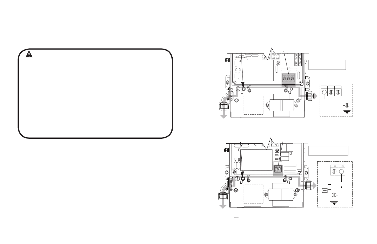
Line Voltage Wiring Fig. 1
WARNING
• DO NOT apply power to operator until instructed to do so.
• The Genie
®
Company recommends that line voltage wiring
be performed by a qualified electrician.
• Be sure that electrical power has been disconnected from the
input power wires being connected to the operator prior to
handling these wires. An appropriate lock-out /tag-out procedure
is recommended.
• Line voltage wiring must meet all local building codes.
• Make sure operator voltage, phase and frequency nameplate
ratings are identical to the job site line voltage ratings.
• Input power wiring must be properly sized for the operators
amperage rating located on the nameplate.
• To reduce the risk of electric shock, make sure the chassis of this
unit is properly grounded.
1) Remove LINE VOLTAGE INPUT PLUG and install proper
fittings and 1/2”conduit.
2) Route proper LINE VOLTAGE wires into operator.
3) Locate LINE INPUT terminals on circuit board. Using
correct connectors, attach wires to LINE INPUTS, and GROUND
terminal.
• Keep low
voltage and line voltage wires separate.
• Route all line voltage wires as shown. Use liquid tight fittings
and conduit.
• Plug all unused conduit holes with liquid tight plugs.
NOTE: LIQUID-TIGHT FITTINGS AND CONDUIT ARE NOT PROVIDED.
GCL-GH
Heavy Duty Operator
www.geniecompany.com 06-12
Figure 1
HIGH
VOLTAGE
INPUT
PLUGS
(Right
& Left)
HIGH
VOLTAGE
INPUT
PLUGS
(Right
& Left)
LINE
GROUND
Optional
Accessory
Modules
Optional
Additional
Transformer
ROUTE HIGH VOLTAGE WIRING
IN THE SHADED AREA AS SHOWN
LINE
GROUND
Optional
Additional
Transformer
ROUTE HIGH VOLTAGE WIRING
IN THE SHADED AREA AS SHOWN
208/240V 480/575V
LINE INPUT
TERMINALS
LINE INPUT
TERMINALS
Three Phase
LINE IN
POWER CONNECTIONS
L1
L3
L2
LINE 1
LINE 2 LINE 3
GND
Single Phase
POWER CONNECTIONS
L1/L1
N/L2
LINE
NEUTRAL
115V
(HOT)
LINE 1
LINE 2
208V
230V
GND
1
Low Voltage Wiring
(SUPPLEMENT TO SECTION 5 OF THE ACCOMPANYING GCL-GH™ INSTALLATION MANUAL)
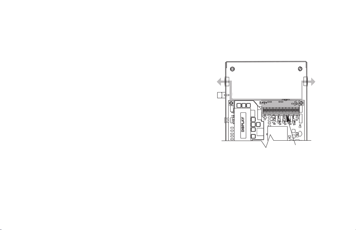
Low Voltage Control Wiring (general) Fig. 2
1) Connect all LOW VOLTAGE control circuit wires to this side
of unit using 1/2” conduit or flexible convoluted tubing.
• Keep low voltage and line voltage wires separate.
• Route all low voltage control wiring as shown. Use liquid tight
fittings and conduit. This includes all control circuit wires such as
wall controls, timers and single button input devices as well as
radio control and safety circuit wiring. See Figs 2 through 10 in
this section.
• Plug all unused conduit holes with liquid tight plugs.
LOW
VOLTAGE
INPUT
PLUGS
(Left &
Right)
ROUTE LOW VOLTAGE WIRING
IN THE SHADED AREA AS SHOWN
NOTE: For a detailed description of control wire terminals see Appendix B in
the Standard GCL-GH
NOTE: LIQUID-TIGHT CONDUIT AND FITTINGS ARE NOT PROVIDED
GCL-GH
™
Installation Manual.
Heavy Duty Operator
www.geniecompany.com 06-12
Figure 2
LOW VOLTAGE
CONTROL WIRE
TERMINALS
2
 Loading...