


Installer:
Leave this manual with homeowner.
Homelink® is a registered trademark of Johnson Controls Technology Company.
Car2U® is a registered trademark of
Lear Corporation.
© The Genie Company 2010. X900-745
A LW AY S AT Y O U R C O M M A N D
Models 1022/1024/1042
GARAGE DOOR OPENERS
Includes INTELLICODE® Remote Control Safe-T-Beam® System must be installed to close door.
For use only with sectional doors. Your Residential Opener comes with a Rail Assembly which is standard
for up to a 7 foot high door.
Homelink® and Car2U® compatible
For Answers and Assistance:
1.800.354.3643
or visit www.geniecompany.com
SAVE THIS MANUAL FOR FUTURE REFERENCE
PN# 3642036534, 5/18/2011 REV.2
SAFETY INFORMATION
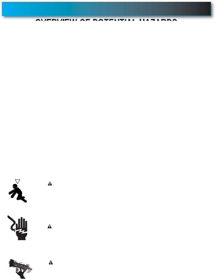
OVERVIEW OF POTENTIAL HAZARDS
READ THIS SAFETY INFORMATION
Garage doors are large, heavy objects that move with the help of springs under high tension and electric motors. Since moving objects, springs under tension, and electric motors can cause injuries, your safety and the safety of others depend on the owner or user of this system to read, understand and implement the information in this manual. If you have questions or do NOT understand the information presented, contact The Genie Company or an authorized Genie® Dealer.
The safety alert symbol and following signal words DANGER, WARNING, and CAUTION are used throughout this manual to call attention to and identify different levels of hazard and special instructions.
 This is the safety alert symbol. This symbol is placed next to signal words and messages to help you identify important safety information
The word:
 DANGER indicates an imminently hazardous situation which, if NOT avoided, will result in death or serious injury.
 WARNING indicates a potentially hazardous situation which, if NOT avoided, could result in death or serious injury.
  CAUTION indicates a potentially hazardous situation which, if NOT avoided, may result in injury or property damage.
The word NOTE is used to indicate important steps to be followed, important considerations, or location of parts.
IMPORTANT SAFETY INSTRUCTIONS
READ AND FOLLOW ALL INSTRUCTIONS
SAVE THESE INSTRUCTIONS
|
POTENTIAL |
EFFECT |
PREVENTION |
||
|
|
HAZARD |
|||
|
|
|
|
||
|
|
|
|
WARNING: |
Keep people clear of opening while door is moving. |
|
|
|
|
||
|
|
|
|
Do NOT allow children to play with the door operator. |
|
|
|
|
|
Could result in Death |
|
|
|
|
|
Do NOT operate a door that jams or one that has a broken spring. |
|
|
|
|
|
or Serious Injury |
|
|
|
|
|
|
|
|
MOVING DOOR |
|
|
||
|
|
|
|
|
|
|
|
|
|
WARNING: |
Turn OFF power before removing operator cover. |
|
|
|
|
When replacing cover, make sure wires are not pinched or near |
|
|
|
|
|
|
|
|
|
|
|
Could result in Death |
moving parts. |
|
|
|
|
|
|
|
|
ELECTRICAL |
or Serious Injury |
Operator must be properly grounded. |
|
|
|
|
|
||
|
|
SHOCK |
|
|
|
|
|
|
|
|
|
|
|
|
|
WARNING: |
Do NOT try to remove, install, repair or adjust springs or anything to |
|
|
|
|
|
which door spring parts are fastened, such as, wood blocks, steel |
|
|
|
|
Could result in Death |
brackets, cables or other like items. |
|
|
HIGH |
or Serious Injury |
Installations, repairs and adjustments must be done by a trained door |
|
|
|
|
|||
|
|
|
system technician using proper tools and instructions. |
||
|
|
SPRING |
|
||
|
|
|
|
||
2 |
|
TENSION |
|
|
|
|
|
|
PN# 3642036534, 02/26/2010 REV. 1 |
||
|
|
|
|
||

TABLE OF CONTENTS
SECTION . . . . . . . . . . . . . . . . . . . . . . . . . . . . . . . . . . . . . . . . . PAGE SAFETY INFORMATION . . . . . . . . . . . . . . . . . . . . . . . . . . . . . . . . . 2 OPENER FEATURES. . . . . . . . . . . . . . . . . . . . . . . . . . . . . . . . . . . . 3 SAFETY FEATURES . . . . . . . . . . . . . . . . . . . . . . . . . . . . . . . . . . . . 3
PRE-INSTALLATION CHECK LIST . . . . . . . . . . . . . . . . . . . . . . . 4-5
RECOMMENDED TOOLS . . . . . . . . . . . . . . . . . . . . . . . . . . . . . . . . 6 PARTS IDENTIFICATION . . . . . . . . . . . . . . . . . . . . . . . . . . . . . . . 6-7
KEY ILLUSTRATIONS. . . . . . . . . . . . . . . . . . . . . . . . . . . . . . . . . . . 8
SAFETY INSTALLATION INFORMATION. . . . . . . . . . . . . . . . . . . . 9
INSTALLATION
1 OPENER ASSEMBLY . . . . . . . . . . . . . . . . . . . . . . . . . . . . 9-11 2 INSTALLATION . . . . . . . . . . . . . . . . . . . . . . . . . . . . . . . . 12-14
3 WALL BUTTON INSTALLATION . . . . . . . . . . . . . . . . . . . 15-16 4 SAFE-T-BEAM® SYSTEM INSTALLATION . . . . . . . . . . . 17-18 5 CONNECTING TO POWER . . . . . . . . . . . . . . . . . . . . . . . . . 19
ADJUSTMENTS
6 LIMIT SWITCHES & FORCE ADJUSTMENT . . . . . . . . . 20-22 KEYED EMERGENCY RELEASE . . . . . . . . . . . . . . . . . . . . 21 CONTACT REVERSE TEST. . . . . . . . . . . . . . . . . . . . . . . . . 22
7 PROGRAMMING REMOTE CONTROLS. . . . . . . . . . . . . . . 23 8 BATTERY/VISOR CLIP INSTALLATION . . . . . . . . . . . . . . . 24 9 LIGHT BULB AND LENS INSTALLATION . . . . . . . . . . . . . . 24 SAFETY INSTRUCTIONS . . . . . . . . . . . . . . . . . . . . . . . . . . . . . . . 25
MAINTENANCE & TROUBLESHOOTING
10 ROUTINE MONTHLY MAINTENANCE . . . . . . . . . . . . . . . . 25 WIRING DIAGRAM . . . . . . . . . . . . . . . . . . . . . . . . . . . . . . . 26 TROUBLESHOOTING GUIDE - OPENER. . . . . . . . . . . . . . 27 TROUBLESHOOTING GUIDE - POWER HEAD LED . . . . . 28
TRANSMITTER COMPLIANCE STATEMENT . . . . . . . . . . . . . . . 29
WARRANTY . . . . . . . . . . . . . . . . . . . . . . . . . . . . . . . . . . . . . . . . . . 30
*Opener MUST be installed with the included Wall Console.
**Safe-T-Beam® Safety Reverse System MUST be installed to close door.
OPENER FEATURES
INTELLICODE® Rolling Code Security System.
An electronic rolling code system that enhances the security of the door opener by continuously changing the access code each time the remote control is used. The door opener responds to each new code only once. An access code copied from a working system and tried again will not control the door opener.
Lighted Wall Console*
Operates door opener from inside garage.
(Refer to section 3)
and Car2U® compatible.
Follow the Homelink® or Car2U® instructions in your car owner’s manual.
SAFETY FEATURES
Safe-T-Beam® Non-Contact Reversing System**.
Puts an invisible beam across the door opening. The door stops and reverses to the full open position if anything passes through the beam. Red or green LED indicator lights on the power head provide a self diagnostic code if an operational problem exists. (Refer to Section 10.)
Safe-T-Reverse® Contact Reversing System.
Automatically stops and reverses a closing door within 2 seconds of contact with an object. (Refer to Section 6.)
Safe-T-Stop® Timed Reversed System.
Automatically opens a closing door if it fails to close completely within 30 seconds.
Watch Dog™ Monitoring System.
Monitors the Safe-T-Beam® system to ensure proper functionality and will automatically stop and reverse a closing door if a problem is detected.
Automatic Lighting System.
One bulb lighting supplies up to 75 watts of light for safer evening exits and entries. Turns ON when door is activated and automatically turns OFF 3 minutes later.
Manual Emergency Release.
Manually releases door from door opener. Use during a power failure or other emergency to allow manual opening and closing of door. (Refer to Section 6.)
PN# 3642036534, 02/26/2010 REV. 1 |
3 |
|
PRE-INSTALLATION CHECK LIST FOR HELP-1.800.354.3643 OR WWW.GENIECOMPANY.COM
Things to consider if you are planning to "Do-it-yourself." This opener is designed for use with SECTIONAL doors only.
In many cases you will be replacing an existing door opener with a new one, however, if this will be the first opener installed there are some pre-installation issues which need to be addressed. They are as follows:
The Genie Company recommends that you read and fully understand all information and instructions contained herein before choosing a "Do-it-yourself" installation. Any questions should be directed to The Genie Company or an authorized Genie® Dealer.
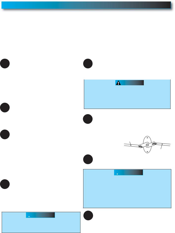
(The issue numbers below refer to the circled numbers in the illustrations on page 5.)
1 |
Check your ceiling where the power |
5 |
You need a properly grounded 110-120 Volt |
|||
head of your new unit will be mounted. |
power supply available. The outlet should be |
|||||
Plan |
how you will be mounting the power head. |
no more than 3 feet from the power head once it is |
||||
It is possible that ceiling joists may not be in the |
mounted. (Refer to Section 5.) |
|||||
position needed with respect to the garage door |
|
|
|
|
||
opener. It may be necessary to add an |
|
|
WARNING |
|
||
additional bracket and fasteners (not included |
DO NOT USE AN EXTENSION CORD! |
|||||
with your new door opener kit). |
||||||
DO NOT USE A PORTABLE GENERATOR! This |
||||||
(Refer to Section 2.) |
||||||
product is designed to operate on |
||||||
|
|
|||||
|
|
standard house current. |
||||
2Check the wall directly above the garage DO NOT USE ALTERNATE POWER SUPPLIES. door. The door opener’s header bracket
must be securely fastened to this wall. Insure that the structure will provide a strong mounting location. (Refer to Section 2.)
3Check to see if the mounting location
for the Safe-T-Beam® System is clear from
obstruction and has a wood surface available for attaching the mounting brackets. The brackets may be attached to concrete if necessary but extra tools and special fasteners (not supplied) will be required. (Refer to Section 4 and 5.)
6 To avoid damage to your door and/or opener, make sure you disable and/or
remove any door locks, ropes, and/or cables (NOT door lift cables) prior to installing your opener. (Refer to Section 1.)
Remove
Remove
7Insure that your door is properly balanced and moving freely. (Refer to Section 2.)
NOTE: Mounting brackets must be installed within code specifications.
4 |
Is your sectional garage door made of |
aluminum, light-weight steel, fiberglass |
or glass panels? Additional support bracing must be added to these type doors. If this is the case, please contact the door manufacturer or authorized dealer so that they can furnish you with a "bracing kit." (Refer to Section 2.)
 WARNING
To reduce the risk of injury to persons or damage to property - Use this opener only with sectional doors.
 WARNING
If your door jams, binds, is improperly balanced or has a broken spring, have it repaired or adjusted by a trained door system technician. Door springs, cables, pulleys, brackets and associated hardware are under extreme tension and can cause serious injury or death.
8(NOT SHOWN) If your garage does not have a separate entry door, you should consider
an emergency release kit (GER-2) for installation on your garage door. (See emergency release kit installation notes on page 21.)
4 |
PN# 3642036534, 02/26/2010 REV. 1 |
|
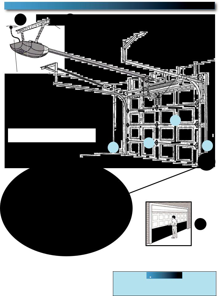
TYPICAL SECTIONAL DOOR INSTALLATION
FOR HELP-1.800.354.3643 OR WWW.GENIECOMPANY.COM
5 Pg. 19 |
1 Pg. 13 |
2 Pg. 12-13 |
|
TYPICAL SUPPORT |
ADDED |
|
BRACKET |
|
|
HEADER BRACKET |
|
|
(NOT PROVIDED) |
|
|
MOUNTING BOARD |
|
|
|
BRACES
POWER CORD
(APPROX. 45 IN.) TO 120V GROUNDED OUTLET
EXTENSION SPRING
OR
TORSION SPRING
NOTE: This opener is designed for use with SECTIONAL doors only.
|
|
|
|
|
|
|
|
4 |
|
|
||
|
|
|
|
|
|
|
|
Pg. 14 |
|
|
||
|
|
|
|
|
|
|
|
|
|
|
|
|
|
|
|
|
|
|
|
|
|
|
|
||
|
|
|
|
|
|
|
|
|
|
|
Pg. 17-18 |
|
Pg. 17-18 |
|
|
6 |
|
|
|
|
|
|
|||
|
|
|
|
|
|
|
||||||
|
|
|
|
|
|
|
|
|
3 |
|
||
3 |
|
|
|
|
|
|
|
|
|
|||
|
|
|
|
Pg. 11 |
|
|
|
|
|
|||
|
|
|||||||||||
|
|
|
|
|
||||||||
|
|
|||||||||||
|
|
|
|
|
|
|
|
|
|
|
|
|
|
|
|
|
|
|
|
|
|
|
|
|
|
SAFE-T-BEAM®
MAX. 6" MIN. 5"
7
Pg. 12
SECTIONAL DOOR
 WARNING
To reduce the risk of injury to persons or damage to property - Use this opener only with sectional doors.
PN# 3642036534, 02/26/2010 REV. 1 |
5 |

RECOMMENDED TOOLS
FOR HELP-1.800.354.3643 OR WWW.GENIECOMPANY.COM
|
3/16" Drill Bit |
Pencil |
Carpenter’s level |
|
|
Drill |
|
|
|
|
Ratchet |
Adjustable wrench |
Wire strippers |
|
|
Tape measure |
|
|
|
|
|
|
|
|
Step ladder |
Safety Glasses |
1/4", 7/16", 3/8" and |
Hammer |
|
|
||||
|
Phillips screwdriver |
|
||
|
1/2" |
Sockets |
|
|
|
|
|
||
PARTS IDENTIFICATION - Not Shown Full Size .
|
|
|
|
|
|
|
|
|
|
|
|
|
|
|
ARRANGING BOX CONTENTS FOR ASSEMBLY |
|
|
||
|
|
|
|
|
ORGANISATION DU CONTENU DE LA BOÎTE POUR LE MONTAGE |
|
|
||
|
|
|
|
|
DISPOS CIÓN DEL CONTEN DO DE LA BOLSA PARA EL MONTA E |
|
|
||
|
|
|
|
|
|
|
Remove i te nal box s |
|
|
|
|
|
|
|
|
|
nl ve l s bo t s i |
t rn s |
|
|
|
|
|
|
|
|
Qu e l s c ja i |
te nas |
|
|
|
|
|
|
|
R move ens Box and motor power h ad |
|
||
|
|
|
|
|
|
E l ver a bo |
e des e t l es t a t te mo or ée |
|
|
|
|
|
|
|
|
Q i e la a a de a l nte y l mo or de a c ja |
e con ol |
|
|
|
|
|
|
|
|
Ca efu y emove th rd r il wi h ha n |
|
||
|
|
|
|
|
|
tt ched) a d p ace on oor |
|
||
|
|
|
|
|
|
E le er o gne seme t e t o s ème r i ( vec a |
|
||
|
|
|
|
|
|
ch î |
e at a hée et e p a er ur e sol |
|
|
|
|
|
|
|
|
Cu dados men e qui e el t rcer |
el ( on a |
|
|
|
|
|
|
|
|
cade a |
cop ada) y ponga en el p so |
|
|
|
|
|
|
|
|
A range hree sma l box s for e sy acc ss |
|
||
|
|
|
|
|
|
Ar a ger es |
r is e i es b î es de m ni re à ou |
|
|
|
|
|
|
|
|
|
vo r y a cé er ac ement |
|
|
|
|
|
|
|
|
D ponga a |
t es c j s pe ueñ s pa a t ne ac eso |
|
|
|
|
|
|
|
|
|
fá il |
|
|
|
|
|
|
|
|
R move ai sec i ns not conne ted |
|
||
|
|
|
|
|
|
|
o cha n |
|
|
|
|
|
|
|
|
n ev r l s s c io s de a l non onn c ées |
|
||
|
|
|
|
|
|
|
à la ha ne |
|
|
|
|
|
|
|
|
Q |
i e as s c io es de i l no |
one t das a |
|
|
|
|
|
|
|
|
a c dena |
|
|
|
|
|
|
|
|
Ar ange ra s in ine and pu l p ast c s eeve o cha n |
|
||
|
|
|
|
|
|
r ang r es a ls n l gne |
t t er ur e man hon en p a t que |
|
|
|
|
|
|
|
|
our e d gag r de a ch îne |
|
|
|
|
|
|
|
|
|
D spo ga os r e e en l n a y es re a c m s de p ás co f era |
|
||
|
|
|
|
|
|
|
de a c dena |
|
|
|
|
|
|
|
Fo low nst uct ons n he nsta la |
ion Manual for a sembly teps |
|
|
|
|
|
|
|
|
Proc der se on l s in tru t ons s ipu ées da s le m nuel d nst l at on pour es ét pes de |
|
|
||
|
|
|
|
|
montage à su v e |
|
|
|
|
Safety Brochures |
|
|
|
|
Box Contents Sheet |
|
|||
|
|
|
|
|
|
|
|
|
|
|
|
|
|
|
|
|
|
|
|
Child can be pinned under automatic garage door. Death or serious injury can result.
•Never let ch ld walk or run under moving door. .
•Never let ch ld use door opener controls.
•Always keep moving door in sight.
•If person is pinned, push control button or use emergency release.
•Test door opener monthly:
Re e to you owne s manual
|
ace |
- nch ob ect (o 2x4 aid |
a ) on oo |
||||
I |
doo |
a ls to |
eve se on con act |
ad ust opene |
|||
I |
opene s ill |
a ls to eve se doo |
epai o |
ep ace opene |
|||
|
|
Do not emove o |
paint ove |
h s label |
|||
|
Mount wa l cont ol out o ch ld s |
each |
at |
east 5 |
eet above loo ) |
||
|
|
|
ace next o wall cont ol |
© 999 |
|||
|
|
|
|
|
|
|
|
Entrapment Warning
Label
|
|
Header Bracket |
|
Three |
|
|
|
Door |
|
|
|
|
Remote |
|
|
Safe-T-Beam® Sensor |
|
Bracket |
|
Safe-T-Beam® Source |
|
|
||
|
|
|
||
with wire |
with wire |
|
|
|
(Green LED) |
|
|
|
|
(Red LED) |
Wire |
|
|
|
|
|
|
||
|
|
|
|
|
Safe-T-Beam® |
Insulated Staple |
|
Rail Section Clamp |
|
|
|
|||
Source/Sensor Bracket |
|
|
|
|
|
|
|
End Rail Section |
|
|
|
Wall Console |
|
|
Door Arm
Pro Rail (Chain) Section |
OR |
Pro Rail (Belt) Section |
Center Rail Section |
Head Rail (Chain) Section |
Head Rail (Belt) Section |
6 |
PN# 3642036534, 02/26/2010 REV. 1 |
|
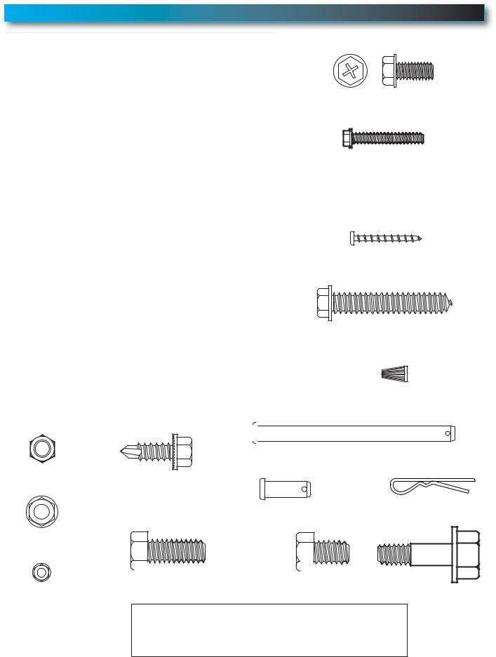
FASTENERS - Shown Full size (See Parts List below for full description.)
|
|
|
|
|
|
BAG NO. |
DESCRIPTION |
QUANTITY |
|||
|
|
|
|
|
|
0 |
RAIL SECTION CLAMP |
2 |
|||
|
|
|
|
|
|
|
RAIL CLAMP BOLT – 5/16''-18 x 5/8'' |
8 |
|||
|
|
|
|
|
|
|
HEX FLANGE NUT – 5/16''-18 |
8 |
|||
|
|
|
|
|
|
1 |
BOLT – 5/16''-18 x 1/2'' |
3 |
|||
|
|
|
|
|
|
2 |
CLEVIS PIN, LONG – 5/16" x 3" |
1 |
|||
|
|
|
|
|
|
|
COTTER PIN |
1 |
|||
|
|
|
|
|
|
|
HEADER BRACKET |
1 |
|||
|
|
|
|
|
|
|
LAG SCREW – 5/16'' x 2'' |
2 |
|||
|
|
|
|
|
|
3 |
HEX BOLT – 5/16''-18 x 3/4'' |
5 |
|||
|
|
|
|
|
|
|
HEX FLANGE NUT – 5/16''-18 |
5 |
|||
|
|
|
|
|
|
|
LAG SCREW – 5/16'' x 2'' |
2 |
|||
|
|
|
|
|
|
4 |
SELF DRILLING SCREW – 1/4''-20 x 3/4'' |
3 |
|||
|
|
|
|
|
|
|
DOOR BRACKET |
1 |
|||
|
|
|
|
|
|
5 |
HEX BOLT – 5/16''-18 x 3/4'' |
3 |
|||
|
|
|
|
|
|
|
SELF LOCKING NUT – 5/16''-18 |
1 |
|||
|
|
|
|
|
|
|
HEX FLANGE NUT – 5/16''-18 |
2 |
|||
|
|
|
|
|
|
|
CLEVIS PIN – 5/16" x 3/4" |
1 |
|||
|
|
|
|
|
|
|
COTTER PIN |
1 |
|||
|
|
|
|
|
|
6 |
WALL CONSOLE ASSEMBLY |
1 |
|||
|
|
|
|
|
|
|
PAN HEAD PHILLIPS SCREW – #4-24 x 1'' |
2 |
|||
|
|
|
|
|
|
7 |
13 MM INSULATED STAPLE |
30 |
|||
|
|
|
|
|
|
8 |
Safe-T-Beam® SOURCE/SENSOR BRACKET |
2 |
|||
|
PHILLIPS HEX SCREW – #10-16 x 1- 1/4'' |
4 |
|||
|
|
|
|
|
|
|
WIRE NUT (GREY) |
4 |
|||
|
|
|
|
|
|
NO NUMBER |
REMOTE WITH BATTERY |
1 |
|||
|
|
|
|
|
|
NO BAG |
Safe-T-Beam® SOURCE/SENSOR & WIRE SET |
1 |
|||
|
|
|
|
|
|
NO NUMBER |
LIGHT COVER - WHITE |
1 |
|||
|
|
|
|
|
|
NO NUMBER |
LIGHT COVER - COLOR |
1 |
|||
|
|
|
|
|
|
|
|
|
|
|
|
|
|
|
|
|
|
|
|
|
|
|
|
Self Locking Nut |
Self-drilling Screw |
|
1/4"-20 x 3/4" |
||
5/16"-18 |
||
|
Hex Flange Nut
5/16"-18
Rail Clamp Bolt - 5/16"-18 x 5/8"
#10-16 x 1-1/4" Phillips Hex Screw
#4-24 x 1" Pan Head
Phillips Screw
Lag screw - 5/16" x 2"
Wire Nut
Clevis pin, long 5/16" x 3"
Clevis pin 5/16" x 3/4"
Cotter pin
|
|
|
|
|
|
|
|
|
|
Hex Bolt - 5/16"-18 x 3/4" |
Hex Bolt |
- 5/16"-18 x 1/2" |
|||||
Shoulder Bolt
Hex Flange Nut 5/16"-18 x 1"
1/4"-20
MISSING ANY PARTS? Please call toll free - 1.800.354.3643
DO NOT RETURN TO POINT OF PURCHASE.
IMPORTANT! - Information needed when calling
• Model number - (located on packaging)
• Store, city, state, and date of purchase
PN# 3642036534, 02/26/2010 REV. 1 |
7 |
|
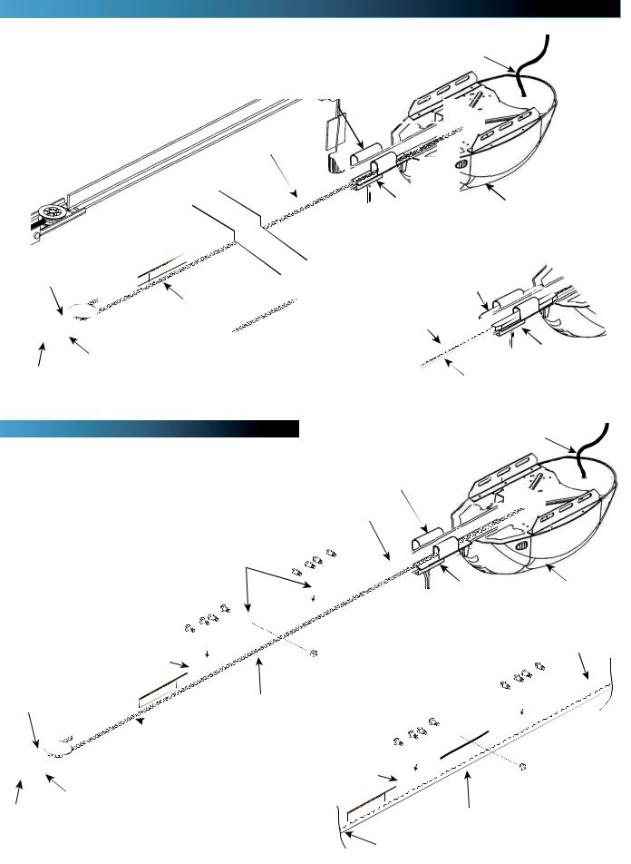
1-PIECE RAIL HARDWARE ASSEMBLED VIEW
FOR HELP-1.800.354.3643 OR WWW.GENIECOMPANY.COM
Tensioner
Header
Bracket
CHAIN
|
|
|
|
|
N |
T |
e |
d |
|
|
|
|
|
s |
act |
||
|
|
|
|
|
dooCon |
|
o |
|
|
|
|
|
S |
meng bu of |
r |
||
|
|
|
h |
boora d |
tc tu e s |
|
||
|
|
|
m |
nut |
|
|
|
|
|
|
|
TENSIONo Dea |
|
|
|
|
|
|
|
I |
jury |
|
|
|
|
|
GH |
SPRNGs |
|
|
|
|
|
|
|
Serio |
|
|
|
|
|
|
||
H C |
use |
|
|
|
|
|
|
|
Can |
|
|
|
|
|
|
|
|
Power Cord
Carriage Assembly
Rail with chain
Chain Connector |
Power Head |
|
Release
Knob
Belt Clamp
|
Chain |
|
|
|
|
|
|
Rail with belt |
|
& Cotter Pin |
|
|
BELT |
Trolley Slide |
|
|
|||
|
|
|
||
Clevis Pin, Long |
|
|
|
|
3-PIECE RAIL HARDWARE ASSEMBLED VIEW |
Power Cord |
|
Carriage Assembly
Rail with chain
Rail Clamps
Chain Connector |
Power Head |
Rail Clamp Bolts
CHAIN
End Rail
|
|
|
|
O |
r |
n ed |
|
|
|
|
|
|
tact r |
||
|
|
|
|
e doCo t |
r |
||
|
|
|
Somc ngr b |
r |
or |
||
|
|
S ON |
bo r |
faci |
u |
n |
|
|
|
man |
|
|
|
|
|
|
|
TEN r Death |
|
|
|
|
|
|
|
njury |
|
|
|
|
|
GH |
SPRNGi us |
|
|
|
|
|
|
Se |
|
|
|
|
|
||
H C |
use |
|
|
|
|
|
|
Can |
|
|
|
|
|
|
|
Tensioner
 Chain
Chain
Rail
Center Rail
Clevis Pin, Long
Header & Cotter Pin
Bracket
|
ON |
|
SIDea |
|
TENy or |
|
INGn u |
SPR |
|
HIGHaue |
Serous |
|
|
C n |
|
h
|
|
O |
|
E |
eet |
|
me |
d |
o |
|
ta o |
S |
r c |
s |
i |
r |
r for |
d |
orufa |
t |
o |
|
|
ma |
|
|
|
|
|
BELT
8 |
PN# 3642036534, 02/26/2010 REV. 1 |
|
IMPORTANT INSTALLATION INSTRUCTIONS  WARNING: To reduce the risk of severe injury or death:
1
AND OPERATION INSTRUCTIONS. (If you have questions or do not understand an instruction, call The Genie Company or an authorized Genie® Dealer.)
2.Install only on a properly balanced sectional garage door. An improperly balanced door could cause severe injury. Have a trained door system technician make repairs or adjustments to cables, spring assemblies, and other hardware before installing the opener.
3.Remove all ropes and remove or make inoperative all locks connected to the garage door before installing opener.
4.Where possible, install the door opener 7 feet or more above the floor. For products having an emergency release, mount the emergency release within reach, but at least 6 feet above the floor and avoiding contact with vehicles to avoid accidental release.
5.Do NOT connect the opener to source of power until instructed to do so.
6.Locate the control button:
•Within sight of door,
•At minimum height of 5 feet so small children are not able to reach it, and
•Away from all moving parts of the door.
7.Install the Entrapment WARNING Label next to the Wall Control button in a prominent location. Install the Emergency Release Tag on or next to the emergency release.
8.After installing the opener, the door must reverse within 2 seconds when it contacts a 1-1/2 inch high object (or a 2 x 4 board laid flat) on the floor.
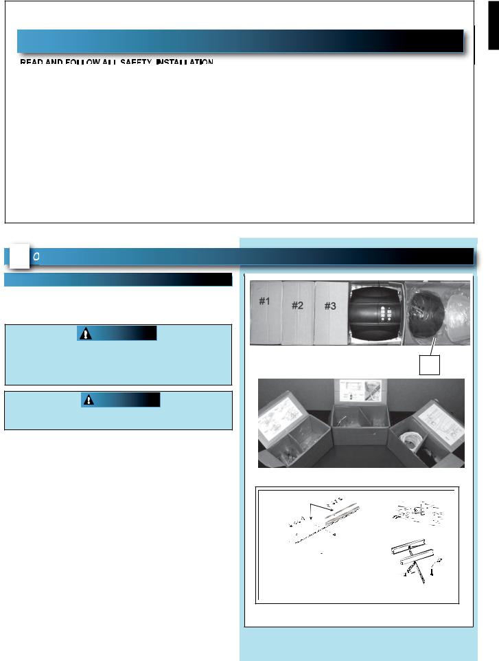
1 PENER ASSEMBLY
FOR HELP-1.800.354.3643 OR WWW.GENIECOMPANY.COM
RAIL ASSEMBLY: Use a clean, flat surface. |
|
|
|
|
NOTE: For 1-piece rail—skip to POWER HEAD & |
|
|
|
|
RAIL ASSEMBLY. |
|
|
|
|
WARNING |
|
|
|
|
To reduce the risk of injury to persons or |
|
|
|
|
damage to property - Use this opener only |
|
|
|
#4 |
with sectional doors. |
|
|
|
|
CAUTION |
|
|
|
|
Do NOT run until opener is fully assembled and |
|
|
|
|
instructed to do so. |
|
|
|
|
NOTE: Three (3) piece rail assemblies are for a 7 |
|
|
|
|
foot high door. |
|
|
|
|
Clear a workspace area to unpack and organize box |
|
|
|
|
and contents for assembly. |
|
|
|
|
1. There are 4 boxes inside the carton. Each box is |
|
|
|
|
numbered 1 - 4. Note that some openers will |
Bag 0 |
|
Bag 2 |
Header Bracket |
contain the same parts and be packaged with |
|
|
||
fewer boxes. Carefully remove the three |
|
|
Header Bracket |
|
internal boxes (Labeled #1, 2, and 3) and place |
|
|
Bolts |
|
them on the floor for easy access (Fig. 1-1). |
|
|
Rail Connector Nuts |
Lag Srews |
These boxes contain assembly parts and the |
|
|
Bolts |
|
contents are organized by assembly tasks. For |
Bag 1 |
Rail |
Bag 3 |
|
quick reference inside the lid of each box there is |
|
|
|
|
a label illustrating the components inside. |
|
|
5/16" Nuts |
|
|
|
|
& Bolts |
|
2. Remove the motor power head and place it on |
|
Power head |
|
|
|
|
|
|
|
the floor for later use. Remove box #4 and |
|
|
Box Label Example |
|
place it on the floor for later use. |
|
|
|
|
|
FIG. 1-1 |
Internal boxes. |
|
|
PN# 3642036534, 02/26/2010 REV. 1 |
9 |
|
 Loading...