


Genie 3022, 2568, 4042, 5024, 4064 User Manual
...Serial Number Decal
PRE-PROGRAMMED 

 REMOTE INCLUDED FOR QUICK & EASY INSTALL
BELT/CHAIN/SCREW DRIVE
GARAGE DOOR OPENER MODELS:
2562, 2568, 3022, 3024, 3042, 3062 , 3064, 4024, 4042, 4062,
4064, 5042, SC1200, CB1000, CB1200
PROGRAMMING, OPERATION & MAINTENANCE MANUAL
Includes INTELLICODE® Remote Control. Safe-T-Beam® system must be installed to close the door. For use only with residential One-Piece or Sectional Overhead Garage Doors. Homelink® and Car2U® compatible
Need help or have questions? STOP For answers and assistance, visit www.GenieCompany.com
or call Customer Service at: 1-800-35-GENIE


INSTALLER: LEAVE THIS MANUAL WITH HOMEOWNER HOMEOWNER: SAVE THIS MANUAL FOR FUTURE REFERENCE
 WARNING
To reduce the risk of injury to persons or damage to property, use this opener only with a one-piece or sectional residential door.
 AVERTISSEMENT
Por réduire le risque de blessures ou de dommages materials, utilisez cet ouvre-porte uniquement pour une porte à section ré sidentielle.
©2015 The Genie® Company, the Genie Logo, Intellicode® and Safe-T-Beam®, are trademarks of GMI Holdings, Inc. d/b/a The Genie® Company.
All other trademarks are property of their rightful owners. Consistent with our policy of continuing product improvements, we reserve the right to change product speci cations without prior notice or obligations. HomeLink is a registered trademark of Gentex Corporation. Car2U is a registered trademark of Lear Corporation.

If you are a homeowner/end user and need help or have questions:
call 800-35-GENIE.
Or visit: www.GenieCompany.com Do not return product to the store.
Alternate language manuals available at: www.GenieCompany.com
Idioma alternativo manuales disponibles en: www.GenieCompany.com
Autre langue manuels disponibles à: www.GenieCompany.com
Safety Information |
|
Safety Noti cations................................................ |
1 |
Important Safety Instructions............................ |
1 |
Important Installation Instructions.................. |
2 |
Features |
|
Safety Features........................................................ |
3 |
Opener Features ..................................................... |
3 |
Safe-T-Beam Protection Function..................... |
3 |
Wall Console Features........................................... |
4 |
Programming Information |
|
Introduction ............................................................. |
5 |
Overview of Powerhead Controls..................... |
5 |
Travel Limits................................................................. |
|
Closing Garage Door (DOWN Limit) |
........ 6 |
Opening Garage Door (UP Limit).............. |
7 |
Force Control.................................................... |
8 |
Contact Reverse Test...................................... |
8 |
Contact Reverse Adjustment...................... |
8 |
Remote Control Programming.......................... |
9 |
Optional Programming |
|
Programming Keypad.................................. |
10-11 |
Programming Vehicle Remotes....................... |
12 |
Clearing Memory for Remotes ........................ |
13 |
Maintenance and Adjustments |
|
Important Safety Instructions.......................... |
14 |
Regular Maintenance.......................................... |
15 |
Remote Battery Replacement.......................... |
15 |
Light Bulb Replacement .................................... |
16 |
Adjustment Guides....................................... |
16-17 |
Locating Safe-T-Beam® Pairs ............................ |
18 |
Wiring Diagram................................................... |
18 |
Troubleshooting.......................................... |
19-20 |
One Piece Door Installation .......................... |
21 |
Warranty................................................................. |
22 |
Safety Information
OVERVIEW OF POTENTIAL HAZARDS READ THIS SAFETY INFORMATION
Garage doors are large, heavy objects that move with the help of springs under high tension and electric motors. Since moving objects, springs under tension, and electric motors can cause injuries, your safety and the safety of others depend on you reading the information in this manual. If you have questions or do not understand the information presented, call your nearest trained door system technician or visit our website at www.GenieCompany.com.
CONVENTIONS USED IN THESE INSTRUCTIONS
The following safety alert symbol and signal words are used throughout this manual to call attention to and identify di erent levels of hazards and special instructions.
This is the safety alert symbol. This symbol alerts you to potential hazards that can kill or hurt you and others. All safety messages will follow the safety alert symbol and the word “DANGER”,“WARNING”, or “CAUTION”.
•DANGER indicates an imminently hazardous situation which, if NOT avoided, will result in death or serious injury.
•WARNING indicates a potentially hazardous situation which, if NOT avoided, could result in death or serious injury.
•CAUTION indicates a potentially hazardous situation which, if NOT avoided, may result in injury or property damage.
• The word NOTE is used to indicate important steps to be followed or important considerations.
Tous les messages concernant la sécurité seront indiqués après un symbole d’alerte de la sécurité et l’une des mentions suivantes “DANGER”, ”AVERTISSEMENT” ou “MISE EN GARDE”.
•DANGER signale une situation dangereuse imminente qui, si elle n’est pas évitée, risque d’entraîner des blessures graves, voire mortelles.
•AVERTISSEMENT signale une situation potentiellement dangereuse qui, si elle n’est pas évitée, risque d’entraîner la mort ou des blessures graves.
•MISE EN GARDE signale une situation potentiellement dangereuse qui, si elle n’est pas évitée, risque d’entraîner des blessures ou des dommages matériels.
•Le terme REMARQUE est utilisé pour signaler les étapes importantes à suivre ou d’importants éléments à prendre en considération.
IMPORTANT SAFETY INSTRUCTIONS
POTENTIAL HAZARD |
|
|
EFFECT |
PREVENTION |
|
MOVING DOOR |
|
! |
WARNING |
Do Not operate unless the doorway is in sight and free of |
|
|
obstructions. Keep people clear of opening while door is moving. |
||||
|
Could result in Serious |
Do Not allow children to play with the door operator. |
|||
|
Do Not change operator control to momentary contact unless and |
||||
|
|
|
Injury of Death |
external reversing means is installed. |
|
|
|
|
|
Do Not operate a door that jambs or one that has a broken spring. |
|
ELECTRICAL SHOCK |
|
! |
WARNING |
Turn o electrical power before removing operator cover. |
|
|
|
Could cause Serious |
When replacing the cover, make sure wires are not pinched or near |
||
|
|
moving parts. |
|||
|
|
|
Injury or Death |
Operator must be electrically grounded. |
|
HIGH SPRING TENSION |
|
! |
WARNING |
door spring parts are fastened such as wood block, steel brackets, |
|
|
|
|
|
Do Not try to remove, repair or adjust springs or anything to which |
|
|
|
Could cause Serious |
cables or any other structure or like item. |
||
|
|
|
Injury or Death |
Repairs and adjustments must be made by a trained service |
|
|
|
|
representative using proper tools and instructions. |
||
IMPORTANTES CONSIGNES DE SÉCURITÉ |
|||||
DANGER POTENTIEL |
|
|
EFFET |
PRÉVENTION |
|
PORTE EN MOUVEMENT |
! |
AVERTISSEMENT |
Utiliser uniquement si la porte est en vue et libre de tout obstacle. |
||
Ne laisser personne se tenir dans l’ouverture de la porte pendant |
|||||
|
|||||
|
|
Pourrait entraîner des |
qu’elle est en mouvement. |
||
|
|
Ne pas permettre aux enfants de jouer avec l’opérateur de la porte. |
|||
|
blessures graves voire la mort |
||||
|
Ne pas modi er la commande de l’opérateur à contact momentané |
||||
|
|
|
|
||
|
|
|
|
à moins qu’un moyen d’inversion externe soit installé. |
|
|
|
|
|
Ne pas faire fonctionner une porte qui bloque ou dont le ressort |
|
|
|
|
|
est cassé. |
|
CHOC ÉLECTRIQUE |
! |
AVERTISSEMENT |
Couper le courant avant d’enlever le couvercle de l’opérateur. |
||
|
|
Pourrait entraîner des |
Lorsque le couvercle doit être remplacé, s’assurer que les ls ne sont |
||
|
|
ni coincés ni près des pièces mobiles. |
|||
|
blessures graves voire la mort |
||||
|
L’opérateur doit être correctement mis à la terre. |
||||
|
|
|
|
||
TENSION ÉLEVÉE RESSORT |
! |
AVERTISSEMENT |
Ne pas essayer d’enlever, réparer ni ajuster les ressorts ou |
||
|
toute autre pièce à laquelle le ressort de la porte est attaché, y |
||||
|
|
Pourrait entraîner des |
compris blocs de bois, supports en acier, câbles ou autres articles |
||
|
blessures graves voire la mort |
semblables. |
|||
|
|
|
|
Les réparations et les réglages doivent être e ectués par |
|
|
|
|
|
technicien quali é qui se sert d’outils appropriés et qui respecte les |
|
|
|
|
|
instructions. |
|
1
Safety Information
IMPORTANT INSTALLATION INSTRUCTIONS
! WARNING
TO REDUCE THE RISK OF SEVERE INJURY OR DEATH
READ AND FOLLOW ALL SAFETY, INSTALLATION AND OPERATION INSTRUCTIONS. If you have any questions or do not understand an instruction, call The Genie Company.
•DO NOT install operator on an improperly balanced door. An improperly balanced door could cause severe injury. Repairs and adjustments to cables, spring assembly and other hardware must be made by a trained service person using proper tools and instructions.
•Remove all ropes, and disable all locks connected to the door before installing operator.
•Where possible, install the door opener 7 feet or more above the oor. For products having an emergency release, mount the emergency release within reach, but at least 6 feet above the oor and avoiding contact with vehicles to avoid accidental release.
•DO NOT connect the operator to the source of power until instructed to do so.
•Locate the wall control button: A) Within sight of door. B) At a minimum height of 5 feet, so small children cannot reach it. C) Away from all moving parts of the door.
•Install the entrapment WARNING label next to the wall button or console, in a prominent location. Install the emergency release handle on the emergency release cord.
•The operator must reverse when the door contacts a 1-1/2 inch high object on the oor at the center of the doorway. This is about the size of a 2” x 4” board laid at.
IMPORTANTES INSTRUCTIONS D’INSTALLATION
! AVERTISSEMENT
POUR RÉDUIRE LES RISQUES DE BLESSURES GRAVES VOIRE MORTELLES
LIRE ET SUIVRE ATTENTIVEMENT TOUTES LES INSTRUCTIONS D’INSTALLATION ET DE FONCTIONNEMENT AINSI QUE TOUTES LES CONSIGNES DE SÉCURITÉ. Si vous avez des questions ou si vous ne comprenez pas une instruction, veuillez contacter directement The Genie Company.
•NE PAS installer l’opérateur sur une porte mal équilibrée. Celle-ci pourrait entraîner de graves blessures. Les réparations et les réglages des câbles, ensembles de ressort ou tout autre article de quincaillerie doivent être e ectués par un professionnel qui se sert d’outils appropriés et qui respecte les instructions.
•Enlever toutes les cordes et désactiver toutes les verrous de la porte avant l’installer l’opérateur.
•Dans la mesure du possible, installer l’ouvre-porte à 2,1 m ou plus au-dessus du sol. Pour les produits dotés d’un cordon de déclenchement d’urgence, installer le déclenchement d’urgence mais au moins à 1,8 m au-dessus du sol en évitant tout contact avec les véhicules pour éviter qu’ils ne soient déclenchés accidentellement.
•NE PAS connecter l’opérateur à la source d’alimentation tant que l’instruction n’est pas donnée.
•Repérer la console murale: A) En vue de la porte. B) À une hauteur minimale de 1,5 m a n que les jeunes enfants ne puissent pas l’atteindre. C) Loin de toutes pièces mobiles de la porte du garage.
•Placer l’étiquette d’AVERTISSEMENT en cas de coinçage à proximité du bouton mural ou de la console de manière à ce qu’elle soit bien en évidence. Installer la poignée du cordon de déclenchement d’urgence.
•L’opérateur doit s’inverser lorsque la porte entre en contact avec un objet d’une hauteur de 3,8 cm placé sur le sol, au centre de l’ouverture de la porte. Ceci équivaut environ à une planche de 5 x 10 cm posée à plat sur le sol.
! WARNING
Operator is equipped with grounded electrical plug for your protection, and only ts grounded electrical outlets. DO NOT alter plug in any way! If your have no grounded outlets, have one installed by a licensed electrician. Operator must be properly grounded to prevent personal injury and equipment damage. NEVER USE AN EXTENSION CORD! Check local building codes for any requirement
that you must have a permanent hard-wired connection. Permanent hard-wired connections must be performed by a licensed electrician using proper tools and instructions.
! AVERTISSEMENT
L’opérateur, qui est équipé d’une prise électrique mise à la terre pour votre protection est compatible uniquement avec des prises électriques mises à la terre. NE PAS modi er la che dune quelconque manière. Si vous n’avez pas de prises mises à la terre, faites-en installer par un électricien agréé. L’opérateur doit être correctement mis à la terre pour éviter les blessures corporelles et des dommages matériels. NE JAMAIS UTILISER DE RALLONGE! Véri ez les codes locaux des bâtiments pour connexions câblées permanente. Les connexions câblées permanentes doivent
être e ectuées par un électricien agréé qui se servira d’outils appropriés et respectera les consignes.
2
 Features
Begin here ONLY AFTER completing assembly and installation of the opener. Review the Assembly and Installation Poster to ensure all steps have been performed. Visit www.GenieCompany.com to download a printable le.
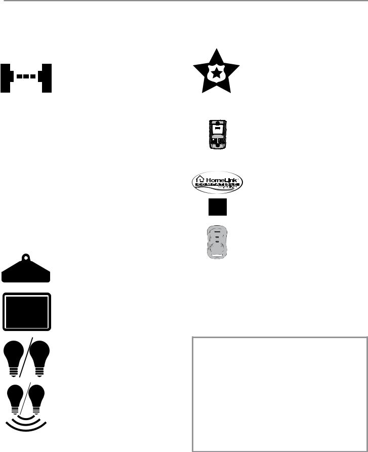
SAFETY FEATURES
Safe-T-Beam® (STB) Non-Contact Reversing System
Puts an invisible beam across the door opening. The door stops and reverses to the full open position if anything passes through the beam. LED indicator lights on the powerhead and on the STBs provide self-diagnos- tics if an operational problems exists.
Safe-T-Reverse® Contact Reversing System
Automatically stops and reverses a closing door within two seconds of contact with an object.
Automatic ForceGuard™ Control
Automatically sets the force required to fully open and close the door for maximum safety.
Door Detect™ Monitoring System
Monitors the Safe-T-Beam® system to ensure proper functionality and will automatically stop and reverse a closing door if a problem is detected.
Manual Emergency Release
Manually releases door from door opener. Used during a power failure or other emergency to allow manual opening and closing of door.
SmartSet® Electronic Programming
Easily adjust the programming to set limits and program new remotes.
Automatic Lighting System
Single or Dual Bulb lighting system supplies light for safer evening exits and entries. Turn ON when door is activated and automatically turns OFF 4 minutes later.
Integrated Motion Detection (Optional on some models)
Lights automatically turn ON when motion is detected for much safer movement through the garage. Lights will turn OFF after four minutes of no motion.
OPENER FEATURES
Intellicode®
An encryption system that enhances the security of the door opener by continuously changing the access code each time the remote is used. The door opener responds to each new code only once. An access code copied from a working system and tried again, will not control the door opener.
Wall Console
Operates door opener from inside garage. The wall console has an indicator light with: Open/Close, Sure-lock™, and independent light control buttons.
Home Link® and Car2U® compatible. See page 12 in this manual, refer to the motor vehicle manual or visit www.GenieCompany.com for instructions.
Pre-Programmed Remote Control
For ease and speed of installation, the remote included with this opener comes from the factory, pre-programmed. No additional steps are required to activate the door using the remote.
NOTE: Use this manual ONLY after completing assembly and installation of the opener.
Review the Assembly and Installation Instructions poster. Check that all steps have been completed.
Safe-T-Beam® (STB) FUNCTION
1.The Safe-T-Beam® has no e ect on the door during an opening cycle.
2.If the Safe-T-Beam® detects an obstruction when trying to close the door, it will not allow the door to close.
3.When the garage door is closing, if Safe-T- Beam® is interrupted by a person or obstacle, the garage door will stop its downward travel and reverse automatically to its fully opened position.
4.If the Safe-T-Beam® System fails, loses power, or is installed improperly, press and hold the wall console“open/close”button until the door reaches its fully closed position. If you release the“open/close”button on the wall console during the closing
movement, the door will reverse automatically to its fully-opened position.
3
Wall Control Features
One of the following wall controls will be included.
NOTE: Wall consoles from other manufacturers may not work with this new opener. Use only the wall control provided with this unit. See warning.
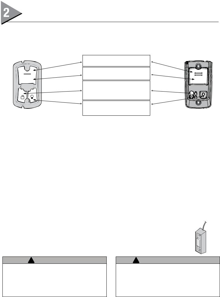
SERIES II WALL CONSOLES
Open/Close Button
Opens and closes door from inside garage.
Indicator Light
-Red indicator backlight is ON. -When Sure-Lock™ in ON, indicator is o .
Sure-Lock™ Button
-LOCK disables controls after door is completely closed.
-UNLOCK allows controls to work normally.
|
Independent Light Control Button |
|
Controls door opener lights from inside |
TYPE 1 |
garage. |
TYPE 2 |
TYPE 1 FEATURES
Indicator Light
Large white button will display Red when wall console is properly wired and Sure-Lock™ is OFF. When Sure-Lock™ is ON, this light is o .
Open/Close Button
Use this button to open or close garage door. When Sure-Lock™ is ON the Open/Close button will CLOSE the door only.
NOTE: Constant button pressure in the CLOSE direction will override STB fault in the powerhead and close door.
Independent Light Control Button
Use this button to turn the powerhead lights ON. Powerhead lighting will remain ON until this button is pressed again or a door action has been completed.
Sure-Lock™ Button
When Sure-Lock™ is ON, and the door is closed, the powerhead cannot be activated by the wall console or a remote.
•PressandreleasetoactivateSure-Lock™(redlightgoesoff).
•PressandreleasetoturnSure-Lock™OFF(redlightgoeson).
TYPE 2 FEATURES
Indicator Light
Large white button will display Red when wall console is properly wired and Sure-Lock™ is OFF. When Sure-Lock™ is ON, this light is o .
Open/Close Button
Use this button to open or close garage door. When Sure-Lock™ is ON the Open/Close button will CLOSE the door only.
NOTE: Constant button pressure in the CLOSE direction will override STB fault in the powerhead and close door.
Independent Light Control Button
Use this button to turn the powerhead lights ON. Powerhead lighting will remain ON until this button is pressed again or a door action has been completed.
Sure-Lock™ Button
When Sure-Lock™ is ON, and the door is closed, the powerhead cannot be activated by the wall console or a remote.
•SlideswitchuptoactivateSure-Lock™(redlightgoesoff).
•SlideswitchdowntoturnSure-Lock™OFF(redlightgoeson).
WALL BUTTON
This is a lighted wall button. Press once to move the door.
If the button is not lighted, check: -White wire connected to terminal “W” -Striped wire connected to terminal“B”
! WARNING
Use of any other wall control can cause unexpected operation of the door and loss of lighting feature. Locate wall console within sight of door but far enough from door to prevent contacting it while operating the console. Control must be at least 5 feet above the oor to prevent small children from operating it.
4
! AVERTISSEMENT
l’utilisation d’une autre commande murale pourrait des résultats in attendus de la porte ainsi que le dysfonctionnement de l’éclairage. Localisez la console murale en vue de la porte et su samment loin de la porte pour éviter tout contact pendant l’utilisation de la console. La commande doit être à une hauteur minimale de 1,5 m au-dessus du sol a n que les jeunes enfants ne puissent pas l’attiendre.
Programming Overview
NOTE: Before programming the operator, check to make sure |
NOTE: The 3 programming buttons are for programming ONLY. |
|
there are no objects in the garage door opening. |
These buttons should NOT be used to operate the opener once the |
|
INTRODUCTION |
Required Programming section has been successfully completed. |
|
|
||
Now that the garage door opener is installed, follow the |
|
|
steps in this manual to program the opener so that the door |
|
|
opens and closes properly and all remote devices operate |
|
|
correctly. The following steps are a guide to setting opener so |
|
|
it functions properly. |
|
|
The following steps list the order of programming the opener’s |
|
|
functional settings for use. |
|
|
1. |
“TRAVEL LIMITS” |
|
2. |
“FORCE and SPEED CONTROLS” |
|
3. |
“REMOTE PROGRAMMING” |
|
Term De nitions: |
|
|
|
|
|
|
|
|
|
Travel Limits Programmable setting to adjust how far door |
|
|
|
|
|
|
|
|
|
travels up or down. |
|
|
|
|
|
|
|
|
|
Force Control refers to how much power is needed to |
|
|
|
|
|
|
|
|
|
move (open/close) a particular door and does NOT require |
|
|
|
|
|
|
|
|
|
programming. |
|
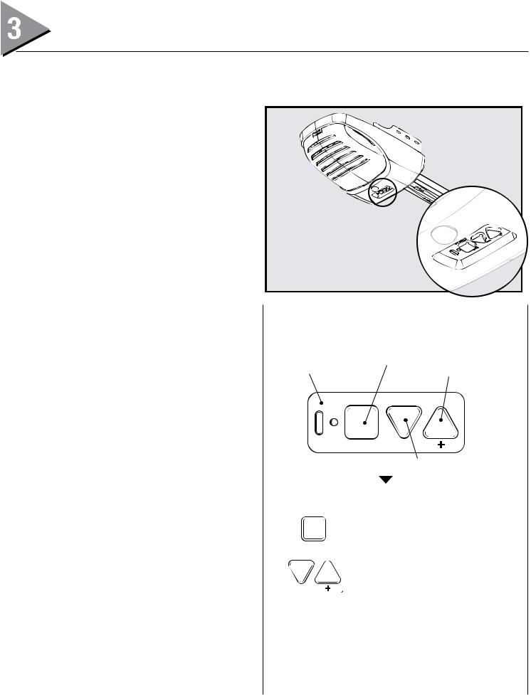
ORIENTATION |
|
|
|
|
|||
Speed Control refers to how fast or slow the opener opens |
|
Standing under the opener’s powerhead – facing the door – looking up |
|||||||
and closes the door. This is factory set and does NOT require |
|
– this is the view you will see of the programming buttons and LEDs. |
|||||||
programming. NOT available on all models. |
|
|
|
|
|
|
|
|
|
Remote Programming synchronizes remote devices |
|
Indicator LED’s |
Programming/Menu |
||||||
(remote, wall console, and keypad) with the powerhead. |
|
|
|
|
Up Travel |
||||
|
|
|
|
|
|
|
|
|
|
OVERVIEW OF POWERHEAD CONTROLS |
|
|
|
PRGM |
|||||
This section describes the programming functions of the |
|
|
|
||||||
|
|
|
|
|
|
|
|||
opener. Use the following information to understand the |
|
|
|
|
|
|
|
||
buttons, LED indicators and products used to program |
|
|
|
|
|
|
|
||
functions. |
|
|
|
SET |
|
|
|||
Powerhead: There are 3 programming buttons and 2 LED |
|
|
|
|
|
||||
|
|
|
|
|
|
|
|||
lights on the powerhead. Each of the buttons are used to enter |
|
|
|
|
|
Down Travel |
|||
and complete the setup programming. The LED lights indicate |
|
|
|
|
|
|
|
||
status or a function change by illuminating ON, OFF, or ON |
|
|
|
DOOR |
|||||
FLASHING in one of three di erent colors: blue, red or purple. |
|
|
|
|
|
|
|
||
There are 4 programs: |
|
|
PRGM |
|
|
|
|
||
1. |
Door Travel Limits. |
|
|
|
Enters into and selects |
||||
|
- This program is used to set how far the door travels |
|
|
|
|||||
|
|
|
|
programming menus. |
|||||
|
up and down. |
|
|
SET |
|||||
|
|
|
|
|
|
|
|||
2. |
Remote Programs (default menu)–only required for added |
|
|
|
Moves door up or down during |
||||
|
remote control transmitters. |
|
|
|
|||||
|
|
|
|
programming and advance |
|||||
|
- Describes how to program remotes to sync with |
|
|
|
|||||
|
|
|
|
through menus. |
|||||
|
additional remote control devices, wall consoles, |
|
|
|
|||||
|
|
|
|
|
|
|
|
||
|
keypads and the powerhead. |
|
|
|
|
|
|
|
|
3. |
Force Setting Program. |
NOTE: While setting limits, the powerhead has a 30 second time-out period when |
|||||||
-This program controls the force applied during the none of the three programming buttons have been selected. If you see two solid red
|
closing and opening of the door. They are factory set |
ashing LEDs or if the LEDs ash red three times and then go OFF, you have run out of |
|
|
and will rarely require adjustment only under certain |
time and must go back to the beginning of the travel limit setting step. |
|
|
|
||
|
circumstances. |
• Just remember—the pointed end of the button (like an arrowhead) |
|
4. Door Speed Program. |
|||
points in the direction the carriage will move when that button is |
|||
- |
This program does not require manually initiated |
||
pushed. |
|||
|
changes. |
||
|
|
||
|
5 |
||
|
|
||

Programming Information
TRAVEL LIMITS
!WARNING
•Make sure doorway is in full view and clear of obstacles and people to avoid injury or property damage.
•DO NOT operate this unit from the wall control before LIMITS are set. Severe damage to the opener could occur.
•The carriage MUST be engaged BEFORE setting limits. See installation poster (if provided) or call Customer Service at 1-800-35-GENIE or visit www.GenieCompany.com.
NOTE: If carriage has NOT been engaged to carriage, do so now.
Before setting limits: con rm wall console red indicator
back light is ON. If not illuminated, See page 19 for troubleshooting. Check STB LED’s: Con rm both LED’s are Illuminated solid. If not Illuminated solid, see page 18 for troubleshooting.
Closing Garage Door (Down Limit)
NOTE: Beginning with garage door in mid travel is recommended but not necessary.
1. Lift door by hand until carriage engages the shuttle on screwdrive or the bullet on the chain/belt.
Screw |
Chain/ |
Drive |
Belt Drive |
Lever must be UP |
Lever must be UP |
READ AND UNDERSTAND STEPS 2-5 BEFORE PROCEEDING
2.Press and hold the down arrow button (–) for two seconds or until the long LED comes on blue. (The round LED stays o .)
PRGM
Steady Blue
SET
3.Release down arrow button (–) and the long LED will begin ashing blue. (Round LED still o .)
PRGM
Flashing Blue
SET
6
!AVERTISSEMENT
•S’assurer que le passage de la porte est visible et dégagé, à savoir sans obstacles ni personne a n d’éviter toute blessure potentielle ou dommage matériel.
•NE PAS utiliser cette unité avec la console murale avant d’avoir réglé les LIMITES. L’ouvre-porte pourrait subir de sérieux dommages.
•La tendeur DOIT être engagée dans le chariot AVANT de régler les limites. Voir le poster d’installation (si fourni) ou appelez le service clientèle au 1-800-35-GENIE ou visitez le site www.GenieCompany.com.
•NE PAS xer de limites en mode batterie de secours. L’alimentation CA DOIT être branchée sur l’ouvre-porte, pendant le réglage des limites, pour assurer un bon fonctionnement.
4.Press and hold the down arrow button (–) to begin closing the garage door. When the garage door is fully closed, release the down button (–). If it has gone too far press and release the up button (+) to move the door up slightly. The door can be moved up or down with the arrow buttons. The door should rest tightly on the oor.
5.Press and release the program/set button—both LEDs
ash blue and then go o .
The DOWN (CLOSED) TRAVEL LIMIT IS NOW PROGRAMMED.
PRGM |
PRGM |
Flashing
Blue
SET
 Loading...