


General Semiconductor ZMM1, ZMM10, ZMM15, ZMM12, ZMM13 Datasheet
...
FEATURES
♦ Silicon Planar Zener Diodes
♦ In Mini-MELF case especially for automatic insertion.
♦ The Zener voltages are graded according to the
international E 24 standard. Smaller voltage
tolerances and other Zener voltages are available
upon request.
♦ These diodes are also available in DO-35 case with the type
designation ZPD1 … ZPD51.
MECHANICAL DATA
Case: Mini-MELF Glass Case (SOD-80)
Weight: approx. 0.05 g
MAXIMUM RATINGS
Ratings at 25°C ambient temperature unless otherwise specified.
SYMBOL VALUE UNIT
Zener Current (see Table “Characteristics”)
Power Dissipation at T
amb
= 25°C P
tot
500
(1)
mW
Junction Temperature T
j
175 °C
Storage Temperature Range T
S
– 55 to +175 °C
ZMM1 THRU ZMM75
ZENER DIODES
1/20/99
.142 (3.6)
.019 (0.48)
∅
Cathode Mark
.063 (1.6)
.134 (3.4)
.055 (1.4)
.011 (0.28)
Mini-MELF
Dimensions are in inches and (millimeters)
SYMBOL MIN. TYP. MAX. UNIT
Thermal Resistance
R
thJA
– – 0.3
(1)
°C/W
Junction to Ambient Air
NOTES:
(1) Valid provided that electrodes are kept at ambient temperature.
ZMM1
(3)
0.7 ... 0.8 6.5 (< 8) < 50 – 26 ... – 23 – 280 340
ZMM2.7 2.5 ... 2.9 75 (< 83) < 500 – 9 ... – 4 – 135 160
ZMM3 2.8 ... 3.2 80 (< 95) < 500 – 9 ... – 3 – 117 140
ZMM3.3 3.1 ... 3.5 80 (< 95) < 500 – 8 ... – 3 – 109 130
ZMM3.6 3.4 ... 3.8 80 (< 95) < 500 – 8 ... – 3 – 101 120
ZMM3.9 3.7 ... 4.1 80 (< 95) < 500 – 7 ... – 3 – 92 110
ZMM4.3 4.0 ... 4.6 80 (< 95) < 500 – 6 ... – 1 – 85 100
ZMM4.7 4.4 ... 5.0 70 (< 78) < 500 – 5 ... +2 – 76 90
ZMM5.1 4.8 ... 5.4 30 (< 60) < 480 – 3 ... +4 > 0.8 67 80
ZMM5.6 5.2 ... 6.0 10 (< 40) < 400 – 2 ... +6 > 1 59 70
ZMM6.2 5.8 ... 6.6 4.8 (< 10) < 200 – 1 ... +7 > 2 54 64
ZMM6.8 6.4 ... 7.2 4.5 (< 8) < 150 +2 ... +7 > 3 49 58
ZMM7.5 7.0 ... 7.9 4 (< 7) < 50 +3 ... +7 > 5 44 53
ZMM8.2 7.7 ... 8.7 4.5 (< 7) < 50 +4 ... +7 > 6 40 47
ZMM9.1 8.5 ... 9.6 4.8 (< 10) < 50 +5 ... +8 > 7 36 43
ZMM10 9.4 ... 10.6 5.2 (< 15) < 70 +5 ... +8 > 7.5 33 40
ZMM11 10.4 ... 11.6 6 (< 20) < 70 +5 ... +9 > 8.5 30 36
ZMM12 11.4 ... 12.7 7 (< 20) < 90 +6 ... +9 > 9 28 32
ZMM13 12.4 ... 14.1 9 (< 25) < 110 +7 ... +9 > 10 25 29
ZMM15 13.8 ... 15.6 11 (< 30) < 110 +7 ... +9 > 11 23 27
ZMM16 15.3 ... 17.1 13 (< 40) < 170 +8 ... +9.5 > 12 20 24
ZMM18 16.8 ... 19.1 18 (< 50) < 170 +8 ... +9.5 > 14 18 21
ZMM20 18.8 ... 21.2 20 (< 50) < 220 +8 ... +10 > 15 17 20
ZMM22 20.8 ... 23.3 25 (< 55) < 220 +8 ... +10 > 17 16 18
ZMM24 22.8 ... 25.6 28 (< 80) < 220 +8 ... +10 > 18 13 16
ZMM27 25.1 ... 28.9 30 (< 80) < 250 +8 ... +10 > 20 12 14
ZMM30 28 ... 32 35 (< 80) < 250 +8 ... +10 > 22.5 10 13
ZMM33 31 ... 35 40 (< 80) < 250 +8 ... +10 > 25 9 12
ZMM36 34 ... 38 40 (< 90) < 250 +8 ... +10 > 27 9 11
ZMM39 37 ... 41 50 (< 90) < 300 +10 ... +12 > 29 8 10
ZMM43 40 ... 46 60 (< 100) < 700 +10 ... +12 > 32 7 9.2
ZMM47 44 ... 50 70 (< 100) < 750 +10 ... +12 > 35 6 8.5
ZMM51 48 ... 54 70 (< 100) < 750 +10 ... +12 > 38 6 7.8
ZMM56 52.0 … 60.0
(4)
<135
(4)
<1000
(5)
typ. +10
(4)
–– –
ZMM62 58.0 … 66.0
(4)
<150
(4)
<1000
(5)
typ. +10
(4)
–– –
ZMM68 64.0 … 72.0
(4)
<200
(4)
<1000
(5)
typ. +10
(4)
–– –
ZMM75 70.0 … 79.0
(4)
<250
(4)
<1500
(5)
typ. +10
(4)
–– –
NOTES:
(1) Tested with pulses t
p
= 5 ms
(2) Valid provided that electrodes are kept at ambient temperature
(3) The ZMM1 is a silicon diode operated in forward direction. Hence, the index of all parameters should be “F” instead of “Z”
Connect the cathode electrode to the negative pole
(4) at I
Z
= 2.5 mA
(5) at I
Z
= 0.5 mA
ZMM1 THRU ZMM75
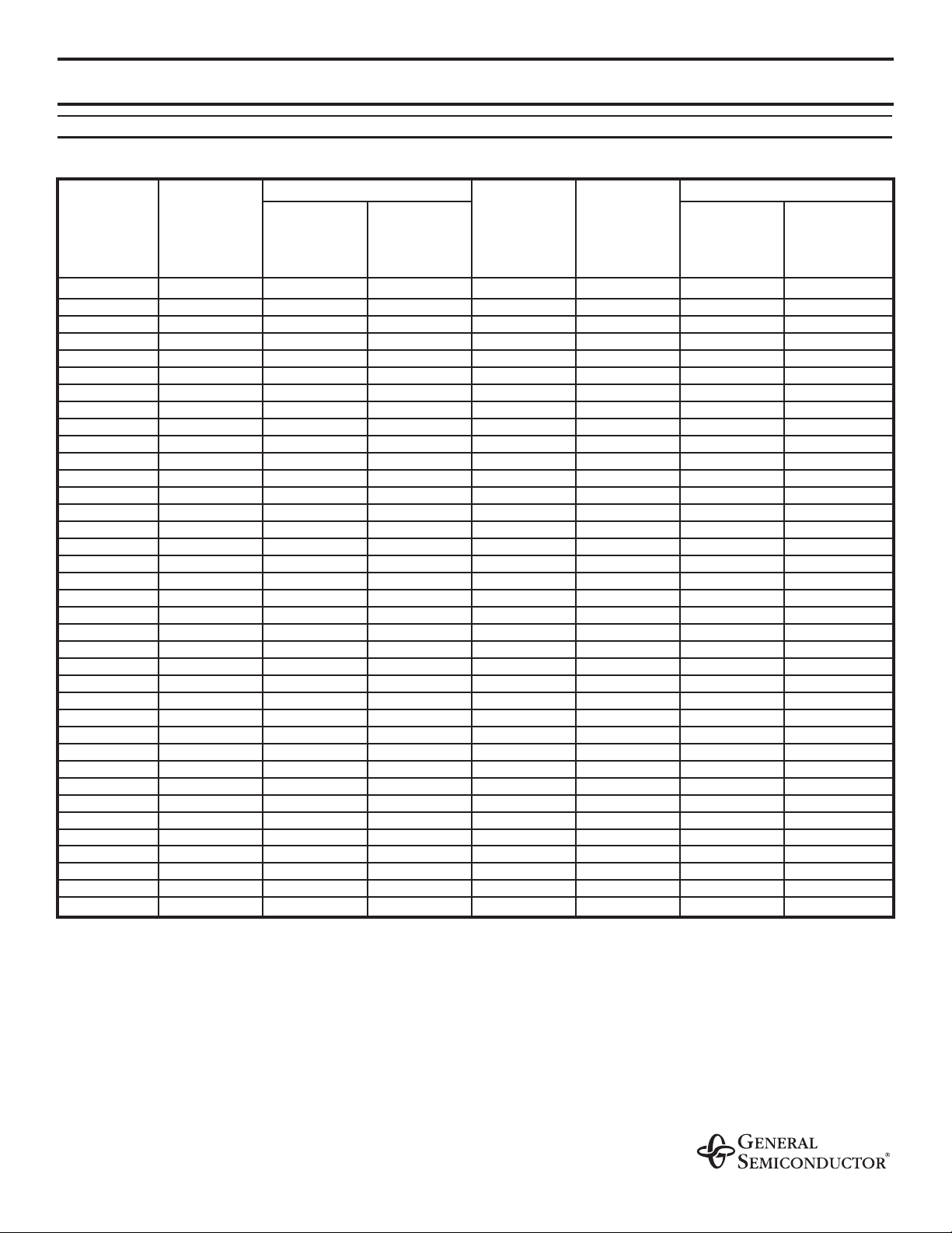
ELECTRICAL CHARACTERISTICS
Ratings at 25°C ambient temperature unless otherwise specified.
Type
Zener Voltage
(1)
at
IZ= 5 mA
VZV
at
IZ= 5 mA
f = 1 kHz
rzjΩ
at
IZ= 1 mA
f = 1 kHz
rzjΩ
Temp. Coeff.
of Zener Voltage
at
IZ= 5 mA
α
VZ
10–4/K
Reverse
Voltage
at
IR= 100 nA
VRV
at
T
amb
= 45°C
IZ= mA
Admissable Zener current
(2)
at
T
amb
= 25°C
IZ= mA
Dynamic Resistance
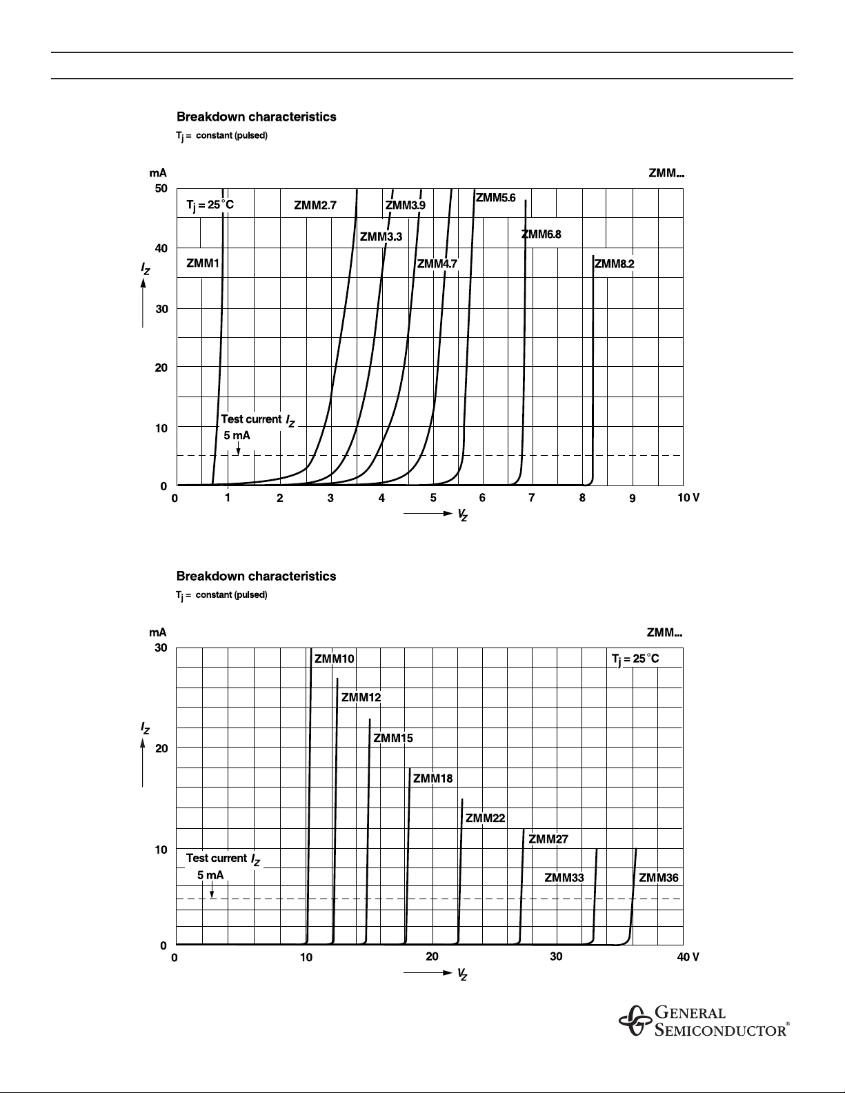
RATINGS AND CHARACTERISTIC CURVES ZMM1 THRU ZMM75
 Loading...