

Page 1
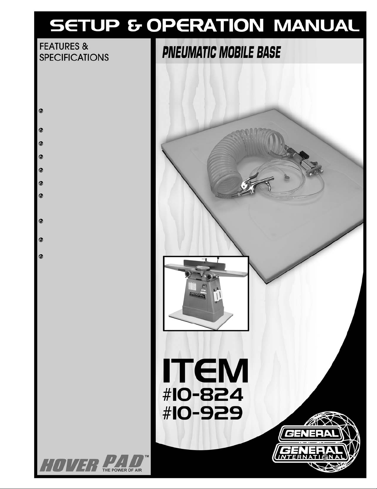
HOVERPAD PNEUMATIC MOBILE BASE ONLY JOINTER SOLD SEPARATELY
Available in 2 sizes:
18" X 24"
(457 x 610 mm) Model #10-824
29" X 29" (737 x 737 mm) Model #10-929
Customizable - May be cut to fit almost
any size exactly.
Effortless motion - Heavy objects move
freely on a cushion of air.
Zero rollback - Stays exactly where
parked.
Safe - Greater footprint and stability than
wheels – No tipping.
Requirements - Standard compressed air
and a smooth floor.
To prevent rocking when parked, the
Hoverpad is itself pliant and also has four
pliant rubber feet which compress and prevent rocking for the vast majority of cases.
The flow control allows adjustable lift from
1/8” to 1/2” (3 to 12 mm). The load is movable
as soon as it lifts.
Model #10-929 will lift up to 1200 LBS (544 kg),
Model #10-824, up to 600 LBS (272 kg).
The Hoverpad will fly over smooth, hard,
airtight surfaces. Flatness doesn’t matter,
but smoothness is critical. Test by applying a suction cup (supplied) to the floor –
if it sticks even slightly, it will work.
THE HOVERPAD™ PNEUMATIC MOBILE BASE IS A
GENERAL-PURPOSE FLAT BASE (LESS THAN ONE
INCH THICK) ONTO WHICH ANY LOAD CAN BE
PLACED AND EASILY MOVED.
REVISION 2 - APRIL 01/07
© COPYRIGHT GENERAL INTERNATIONAL 04/2007
Page 2
THANK YOU
for choosing this Hoverpad Pneumatic Mobile Base model 10-824
or 10-929 by General
® International. This Hoverpad has been carefully tested and inspected
before shipment and if properly used and maintained, will provide you with years of reliable
service. To ensure optimum performance and trouble-free operation, and to get the most from
your investment, please take the time to read this manual before assembling, installing and
operating the unit.
The manual’s purpose is to familiarize you with the safe operation, basic function, and features
of this pneumatic mobile base as well as the set-up, maintenance and identification of its parts
and components. This manual is not intended as a substitute for formal woodworking instruction, nor to offer the user instruction in the craft of woodworking. If you are not sure about the
safety of performing a certain operation or procedure, do not proceed until you can confirm,
from knowledgeable and qualified sources, that it is safe to do so.
Once you’ve read through these instructions, keep this manual handy for future reference.
All component parts of this General® International product are carefully tested and inspected during all stages of
production, and each component is thoroughly inspected upon completion of assembly. Because of our commitment to quality and customer satisfaction, General® International agrees to repair or replace, within a period of
90 days
from date of purchase, any genuine part or parts which, upon examination, prove to be defective in workmanship or material. In order to obtain this warranty, all defective parts must be returned freight pre-paid to
General® International Mfg. Co., Ltd. Repairs attempted without our written authorization will void this warranty.
GENERAL ® INTERNATIONAL WARRANTY
Disclaimer:
The information and specifications in this manual pertain to
the unit as it was supplied from the factory at the time of printing.
Because we are committed to making constant improvements, General
International reserves the right to make changes to components, parts
or features of this unit as deemed necessary, without prior notice and
without obligation to install any such changes on previously delivered
units. Reasonable care is taken at the factory to ensure that the specifications and information in this manual corresponds with that of the unit
with which it was supplied. However, special orders and “after factory”
modifications may render some or all information in this manual inapplicable to your unit. Further, as several generations of this model of pneumatic mobile base and several versions of this manual may be in circulation, if you own an earlier or later version of this unit, this manual may
not depict your unit exactly. If you have any doubts or questions contact
your retailer or our support line with the model number of your unit for
clarification.
GENERAL® INTERNATIONAL
8360 Champ-d’Eau, Montreal (Quebec) Canada H1P 1Y3
Telephone (514) 326-1161 • Fax (514) 326-5555 • www.general.ca
Page 3
Rules for Shop Safety
To help ensure safe operation, please take a moment to learn the machines’ applications and limitations, as well
as potential hazards. General® International disclaims any real or implied warranty and holds itself harmless for
any injury that may result from improper use of its equipment.
1. Do not operate machinery when tired, distracted, or
under the effects of drugs, alcohol or any medication
that impairs reflexes or alertness.
2. The working area should be well lit, clean and free of
debris.
3. Keep children and visitors at a safe distance when
the machine is in operation; do not permit them to
operate the machine.
4. Childproof and tamper proof your shop and all machinery with locks, master electrical switches and
switch keys, to prevent unauthorized or unsupervised
use.
5. Stay alert! Give your work your undivided attention.
Even a momentary distraction can lead to serious
injury.
6. Fine particulate saw dust is a carcinogen that can be
hazardous to health. Work in a well-ventilated area
and whenever possible use a dust collector and wear
eye, ear and respiratory protection devices.
7. Do not wear loose clothing, gloves, bracelets,
necklaces and ornaments while the machine is in
operation.
8. Be sure that adjusting wrenches, tools, drinks and
other clutter are removed from the machine and/or
the table surface before commencing operation.
9. Keep hands well away from blades and all moving
parts. Use a push stick to feed stock, and use a brush,
not hands, to clear away chips and sawdust.
10. Use recommended-speed blades, cutting tools and
accessories for the workpiece material.
11. Be sure the blade or cutting tool has gained full operating speed before beginning to cut.
12. Always use a clean, properly sharpened blade. Dirty
or dull blades are unsafe and can lead to accidents.
13. Do not push or force stock into the blade or cutting
tool. The machine will perform better and more safely
when working at the rate for which it was designed.
14. Use suitable support when cutting stock that does not
have a flat surface. Always hold stock firmly against
the fence when ripping, or against the miter gauge
when cross-cutting.
15. To minimize risk of injury in the event of work piece
kickback, never stand directly in-line with the blade or
in the potential kickback path of the work piece.
16. Avoid working from awkward or off balance positions.
Do not overreach during cutting operation; keep both
feet on floor. Never lean over or reach over the blade
and never pull the work piece over the blade from
behind. Use outfeed support or have an assistant help
when ripping long material.
17. Keep guards in place and in working order. If a guard
must be removed for maintenance or cleaning, be
sure it is properly reattached before using the tool
again.
18. Never leave the machine running with the power “ON”
when not in operation.
19. If using a power feeder, stop the feeder before
stopping the machine.
20. Use of parts and accessories NOT recommended by
General® International may result in equipment malfunction or risk of injury.
21. Never stand on machinery. Serious injury could result
if the tool is tipped over or if blade or cutting tool is
unintentionally contacted.
22. Always disconnect the tool from the power source
before servicing, changing accessories, performing
any maintenance, cleaning, adjustments, or if the
machine will be left unattended.
23. Make sure that switch is in the “OFF” position before
plugging in the power cord.
24. Make sure tool is properly grounded. If tool is equipped
with a 3-prong plug it should be used with a three-pole
receptacle. Never remove the third prong.
Page 4
1.
120 P.S.I. MAX. - ALW
AYS USE SUPPLIED AIR
FLOW CONTR
OL VALVE
Do not exceed 120 P.S.I. of air pressure to the
Hoverpad and never supply unrestricted air directly to your Hoverpad. Do not inflate so that the rubber bearings extend more than 1/2” (12 mm)
beyond the bottom surface of the pad – bearings
will be permanently damaged and warranty will
be void.
2. ABSOLUTELY NO PASSENGERS
This Hoverpad pneumatic mobile base is intended
for use to move machinery and other heavy
objects. It is not designed for people, pets or for any
other purpose. Any attempt to sit, kneel, stand, ride
or “surf” on a Hoverpad, or on a machine or load
installed on a Hoverpad, should be forbidden at all
times because it is dangerous, and can lead to
serious injury.
3. DEFLATE HOVERPAD BEFORE TURNING ON OR
OPERATING MACHINERY
Never turn on or operate any machine installed on
a Hoverpad until the Hoverpad has been deflated
and the air flow valve has been completely shut off.
Make sure the load is securely parked and sitting
stationary and stable on the floor. Failure to ensure
that your machine is completely immobile may
cause serious injury if the machine begins to move
across the floor when in use or as the workpiece is
fed into the blade(s) or cutting tool.
4. SELECT APPROPRIATE LOCATION AND SURFACE
FOR USE
Do not operate on slopes. Use only on hard, solid,
smooth, sturdy and stable surfaces, that are free of
debris or clutter and have minimal cracks, expansion joints or other imperfections that can dissipate
air flow. Tape floor cracks and expansion joints and
cross at an angle.
5.
LOOK BEFORE YOU MOVE THE MACHINE
Ensure that there is a clear path free of any debris,
clutter or obstructions, from your starting point to
the spot where you are re-locating the machine
before moving it. Avoid setting the machine down
on its power cord or air hose.
6. DO NOT FORCE OR OVEREXERT
The Hoverpad pneumatic mobile base is designed
to float and move smoothly (almost frictionless) up
to its rated weight capacity and requires only
steady firm and even pressure to re-locate the
machine or load. If you find that excessive force is
needed: STOP and check for obstructions, over
pressurization or improper installation such as
unevenly distributed load that may cause the
Hoverpad to skid or hop along the floor. Clear dust
or debris from around or beneath the pad, and
reposition the load (if needed) before proceeding.
7. FOLLOW ALL SAFETY RULES AND WARNINGS
SUPPLIED WITH YOUR COMPRESSOR
Improper handling of compressed air or incorrect
use of an air compressor can create hazardous
situations and lead to serious personal injury. Be
sure to read, understand and follow all instructions,
safety guidelines and warnings supplied with the
compressor you will use with this pneumatic mobile
base.
Additional Safety Instructions
Specific to this Mobile Base
BECAUSE EACH SHOP SITUATION IS UNIQUE, NO LIST OF SAFETY GUIDELINES CAN EVER BE COMPLETE.
THE MOST IMPORTANT SAFETY FEATURE IN ANY SHOP IS THE KNOWLEDGE AND GOOD JUDGEMENT OF THE USER.
USE COMMON SENSE AND ALWAYS KEEP SAFETY CONSIDERATIONS, AS THEY APPLY TO YOUR INDIVIDUAL SHOP
SITUATION FIRST AND FOREMOST IN MIND. IF YOU HAVE ANY DOUBTS ABOUT THE SAFETY OF AN OPERATION
YOU ARE ABOUT TO PERFORM: STOP! DO NOT PERFORM THE OPERATION UNTIL YOU HAVE VALIDATED FROM QUALIFIED
INDIVIDUALS IF THE OPERATION IS SAFE TO PERFORM AND WHAT IS THE SAFEST METHOD TO PERFORM IT.
4
Page 5
PNEUMATIC MOBILE BASE
10-824 or 10-929
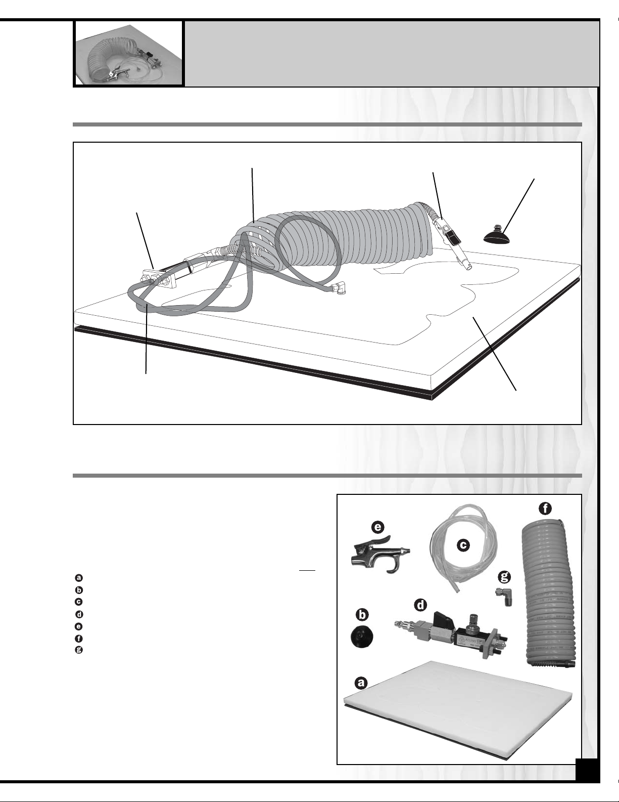
IDENTIFICATION OF PARTS & COMPONENTS
Hoverpad
Suction Cup
Coiled Air Hose
5’ Air Hose
Blow Gun
Air Flow
Controller Assembly
Remove all parts and components from the box and
check for missing or damaged items as per the list of
contents below.
Note: please report any damaged or missing items to
your General International distributor immediately.
Qty
HOVERPAD . . . . . . . . . . . . . . . . . . . . . . . . . . . . . . . . . .1
SUCTION CUP . . . . . . . . . . . . . . . . . . . . . . . . . . . . . . .1
5’ AIR HOSE . . . . . . . . . . . . . . . . . . . . . . . . . . . . . . . . .1
AIR FLOW CONTROLLER ASSEMBLY . . . . . . . . . . . . . .1
BLOW GUN . . . . . . . . . . . . . . . . . . . . . . . . . . . . . . . . . .1
COILED HOSE . . . . . . . . . . . . . . . . . . . . . . . . . . . . . . . .1
“L” FITTING WITH NUT . . . . . . . . . . . . . . . . . . . . . . . . . .1
UNPACKING & CHECKING CONTENTS
5
Page 6

BASIC FUNCTIONS OF THIS HOVERPAD PNEUMATIC MOBILE BASE
This Hoverpad pneumatic mobile base is a general purpose flat
base, less than 1”(25 mm) thick, onto which machinery or other
heavy objects can be placed and easily moved.
Standard compressed air and a smooth hard floor are needed
to operate this Hoverpad. The amount of air volume and pressure required will vary depending on the weight of the load and
the smoothness of the floor, but most loads under 600 LBS (272 kg)
can be floated using a small “pancake” style compressor
putting out 90-120 P.S.I. at between 3-8 CFM.
The Hoverpad cannot be
operated on carpeting, tile
flooring with grout lines, rough or
uneven surfaces or any soft or
unsmooth surface that would
absorb or dissipate the air pressure under the pad.
Compatible surfaces include:
smooth-finished concrete, smoothtextured vinyl, and epoxy painted
concrete floors.
To improve performance, gaps,
cracks or expansion joints can be
filled or taped over and rough surfaces such as broom-finished or
sand textured concrete may be
overlaid or covered with smooth
sheets of metal, plastic or
self-stick vinyl tile.
TEST YOUR FLOOR BEFORE PROCEEDING
Use the supplied suction cup to test the compatibility of your floor
before proceeding with installation.
Sweep or vacuum away any dust, dirt or debris on a small section of flooring in the intended usage area and press the cup
down on the floor until it flattens out.
Note: The cup does not need to be moistened.
If the cup adheres even slightly proceed to the set-up and installation steps described in the following
pages.
If the cup does not stick, the Hoverpad will not work with your flooring surface. Pack up the pad and all
its components in the original packaging for return to your place of purchase for a refund.
6
Page 7

7
ADDITIONAL REQUIREMENTS FOR SET UP
• An extra person for help with lifting • Adjustable wrench
• Phillips head screwdriver • Drill & drill bits
• Tape measure • Pencil
ASSEMBLY AND INSTALLATION INSTRUCTIONS
1. The control fittings are assembled at the factory as
shown.
2. Connect one end of the coiled air hose to the
threaded opening in the bottom of the “t-fitting”
and connect the blowgun to the other end of the
coiled air hose.
NOTE
If you plan to cut your Hoverpad to
size: A bandsaw, reciprocating saw or
other cutting tool will also be needed.
Note: The top of the pad (white side) has a thin protective layer. Peel off this protective layer before continuing.
AIRFLOW DIRECTION
Air inlet
T-Fitting
Ball valve
Adapter
Flow controller
Mounting bracket
with screws & nuts
Air outlet with nut
Air Flo
w Control Assembly Components
Unscrew the nut from the “L” fitting’s hose barb.
Slide the nut onto the 5’ air hose making sure the
threads of the nut are facing outward.
Insert the hose barb of the “L” fitting into the air hose.
Make sure the hose fully covers the hose barb of
the “L” fitting.
Slide the nut from step onto the threads on the
fitting and tighten.
Screw the hose barb “L” fitting into the threaded
hole in the top (white side) of the Hoverpad.
3. The 5’ air hose is connected to both the “L” fitting and the air outlet fitting in the same manner following the steps
listed below.
Use the same connection method to install the opposite end of the 5’ air hose onto the air outlet fitting on the flow
control assembly.
Page 8

4. Close the flow control valve by turning the knurled
knob clockwise.
5. With the help of an assistant, a hoist, or a fork-lift
place your machine or other load roughly
centered on the Hoverpad taking care to avoid
crushing the airhose or hitting the “L” fitting in the
center of the pad.
Note: Follow the manufacturer’s recommendations for
handling or lifting the machine.
6. Run the hose and control assembly up through any
practical or available opening in the base of your
machine.
Note: In some cases, if the base of your machine is
closed and there are no accessible openings in the
cabinet it may be necessary to drill a small hole in the
cabinet in order to pass the hose up through the
machine.
7. Temporarily connect to your compressed air
supply.
Note: Do not surpass 120 P.S.I. of air pressure from your
compressor.
8. Turn the lever to open the ball valve and then
adjust the flow control valve (step 4 above) to take
the minimum required airflow to lift the load.
9. Examine how the load floats and check for level –
an even relatively equal distance from the floor at
all four corners is ideal. If the load floats smoothly
and stays relatively level, skip ahead to the section
entitled “Final Installation”. If the load seems off
balance or does not float smoothly, follow the suggestions listed below in “Leveling the Load and Fine
Tuning” before proceeding to “Final Installation”.
8
OPEN
CLOSE
Page 9

LEVELING
For off balance or off center loads such as the example
shown where the motor
(the heaviest part of the machine) is
installed at one end, the load will not float level with the
floor if the machine is centered on the Hoverpad – this is
normal.
Close the ball valve to shut off the air flow and wait for the
load to settle on the floor. Reposition the load on the
Hoverpad as needed until it floats relatively level with the
floor.
Note: For badly off balance loads, it may be necessary to
apply additional weight or downward pressure to the high
side – minimize airflow and keep the load moving to avoid
hopping.
LEVELING THE LOAD AND FINE TUNING
FINE TUNING
Machines with fully enclosed bases that sit flush to the
floor on all four sides will provide best results with minimal
or no fine tuning required.
Excellent results can also be achieved with open,,or
partially open,,based machines by understanding the
basic principals of weight distribution and following the
suggestions below.
Machines or loads that have a full closed base that
sits flush to the floor distribute their weight best, around the
entire perimeter of the base and the weight is dispersed
evenly across the entire surface of the pad, .
For machines with open or partially open bases, the
weight distribution is limited to the points of contact with
the Hoverpad. Depending on the size and weight of the
load, concentrating the weight on only a few points
rather than evenly distributing it, may cause the Hoverpad
to flex inward at the center (concave) when floating, .
This will affect the performance of the Hoverpad and
cause the corners of the pad to drag or the load to skip
or hop when moved. To remedy this, the weight of the
load needs to be more evenly dispersed.
For open based machines or loads, simply place the
machine on a supplementary platform by cutting a 3/4”
plywood plank (or other flat rigid material) to the size of
the outside dimensions of the contact points (feet) of the
base. Make sure to drill a big enough hole in the center
of the supplementary platform to accommodate the air
hose fitting in the top of the Hoverpad, .
If possible, to avoid the machine shifting off of the supplementary platform, attach the feet of the machine to the
platform with mounting blocks, bolts or screws, .
Note: Make sure fasteners or hardware that are used do not
come into contact with or pierce through the top surface of
the Hoverpad within its penetration border (see illustration
on next page). If needed, countersink holes in the platform
from below to allow your supplementary platform to rest flush
against the Hoverpad.
9
Page 10

For partially open based machines or loads, cut hardwood wedge blocks to size and fit them between the
openings in the base and the Hoverpad as shown. Make
sure the fit is snug in order to more evenly distribute the
weight and to prevent the pad from flexing when floated.
With the load leveled, the weight evenly distributed and
the Hoverpad floating smoothly proceed to the next step
“Final Installation”.
Once the load has been leveled, the weight evenly distributed and the pad floats evenly and moves smoothly, the
final three installation steps involve cutting the Hoverpad to size (if desired), permanently securing the machine to
the Hoverpad (also if desired) and permanently installing the control assembly on the machine or load.
CUTTING OR RE-SIZING THE HOVERPAD
If you choose to, the Hoverpad can be cut or re-sized to
come close to, or match the footprint of your machine.
This can allow you to maximize floor space and limit gaps
between adjacent objects or walls.
Note: Mark the position and orientation of the load on the
Hoverpad before removing the load and cutting the pad.
Before trimming the Hoverpad, mark the outside perimeter of your cut and validate that the intended cut area is
outside the penetration border (see below defined by the
routed groove in the top and 1/4” (6.3 mm) outside the
edge of the rubber feet on the bottom) – Make no cuts or
penetrations of any kind inside of the border. Cutting or
piercing the pad in any way inside of the penetration
border will lead to unit failure and will void the warranty.
Using a bandsaw, reciprocating saw or other cutting tool
that is used to cut wood, trim the excess from the pad to
match the pad size
(outside of the limitations of the penetration
border) to the footprint of your machine.
If the footprint of your machine sits inside of the penetration border trim the pad only to the penetration border.
Do not move the machine to line up with an edge of the
border as this will shift the previously leveled weight.
SECURING
THE LOAD TO THE HOVERPAD
Bolts or screws (not supplied) may be installed into or
through the Hoverpad
(outside of the penetration border).
Cleats may also be used on either the inside or outside
corners
(as shown) of cabinet style bases to hold the
machine from sliding on the Hoverpad, .
FINAL INSTALLATION
PENETRATION BORDER
Do not cut inside the perimeter of
these dotted lines.
TOP VIEW
BOTTOM VIEW
10
Page 11

OPERATION
WARNING!
TO AVOID ACCIDENTS OR INJURIES: NO PASSENGERS ALLOWED! DO NOT ALLOW ANYONE, AT ANY
TIME FOR ANY REASON, TO RIDE ON THE HOVERPAD OR ON ANY LOAD OR MACHINE INSTALLED
ON A HOVERPAD.
When relocating a load installed on a Hoverpad, follow the basic instructions listed below.
1. Always turn off and unplug any machine installed
on a Hoverpad before moving or relocating it.
2. With the ball valve on the control assembly in the
“closed” position, connect the compressed air source
to the air inlet fitting – do not to exceed 120 P.S.I. of air
pressure from the compressor.
Note: Exceeding 120 P.S.I. will damage the Hoverpad.
3. If necessary, clear a path to the relocation point.
Remove any debris, tools, trash or other clutter on the
floor that may be in the way, and use the attached
blow gun to clear away sawdust or woodchips that
may obstruct, diffuse or impede airflow under the
pad .
4. Turn the ball valve to the “open” position and wait a
few seconds for the load to lift and level.
5. Move the machine or load to the desired location in
the shop. Depending on your type of flooring, when
moving a load, the Hoverpad will make a light hissing
or squeaking sound – this is normal.
6. Always maintain control over the load or machine you are moving by keeping your hands on the load at all
times . Never push on the load or machine and let it float away freely .
7. If the pad skips or hops along the floor when moving, adjust the flow control valve to take the least amount of
air pressure required to remedy the problem.
Helpful Hint: Start by turning down the air flow to remedy skipping or hopping. Assuming the load is leveled, evenly distributed on
the pad, and there are no obstructions or debris under the pad, a load that hops or skips when moving is usually an indication
that too much air (rather than too little) is being used to float the load.
8. Unlike mobile bases on fixed wheels, the Hoverpad allows for omni-directional movement. The load can be
moved or rotated as needed in any direction .
9. With the load or machine moved to the desired location, turn the ball valve to the “closed” position to shut
off the air flow and park the load.
Note: Avoid setting the machine down on its’ power cord or
air hose.
10. Make sure the load or machine is securely parked
and sitting stationary and stable on the floor and dis
connect from the compressed air source before plugging in or turning on the machine.
Squeeze down
Air
Dust
11
INSTALLING THE CONTROL ASSEMBLY
Install the controls in a convenient, accessible location on
the machine or load. The control mounting bracket hole
pattern, , shows the mounting hole size and placement
required to attach the mounting bracket (and the control
assembly) to your machine or load.
9/32” (7 mm)
1.5” (38 mm)
17/32” (13.4 mm)
Page 12

12
PARTS LIST
PNEUMATIC MOBILE BASE
PART N0. REF. NO. DESCRIPTION SPECIFICATION QTY
10824-03 19081004 FLAT WASHER WITH RUBBER 6
10824-04 50161035 METAL SCREW 3/16" X 1/2"L 6
10824-07 19081005 RUBBER FEET 4
10824-08 50161034 METAL SCREW 5/32" X 5/8" L 4
10824-09 51801001 AIR INLET P20 1/4" PT 1
10824-10 51804001 T-FITTING 1/4" PT 1
10824-11 51805001 BALL VALVE 1/4" PT 1
10824-12 51806001 FLOW CONTROLLER 02B 1/4" P-46445 1
10824-13 50152043 CAP SCREW 1/4"-18UNC X 7/8"L 2
10824-14 19081007 MOUNTING BRACKET 1
10824-15 50251001 NUT 1/4"-18UNC 2
10824-16 51802001 AIR OUTLET WITH NUT CIN1/4"PT 1
10824-17 51807001 AIR HOSE 6 X 5' 1
10824-18 51803001 “L” FITTING WITH NUT LIN1/4"PT90° X 6 MM 1
10824-20 19081008 SUCTION CUP RUBBER 1
10824-21 51807002 COILED HOSE 8 X 3M,1/4" PT 1
10824-22 51808001 BLOW GUN 1
10824-23 51802002 ADAPTER 1/4"PT 1
*
Hoverpad assembly not
available seperately
Page 13

13
NOTES
Page 14

IMPORTANT: When ordering replacement parts, always give the model number, serial number of
the machine and part number. Also a brief description of each item and quantity
desired.
10-824 / 10-929
8360, Champ-d’Eau, Montreal (Quebec)
Canada H1P 1Y3
Tel.: (514) 326-1161
Fax : (514) 326-5565
Parts & Service
Fax : (514) 326-5555 Order Desk
orderdesk@general.ca
www.general.ca
 Loading...