

Page 1
SETUP & OPERATION MANUAL
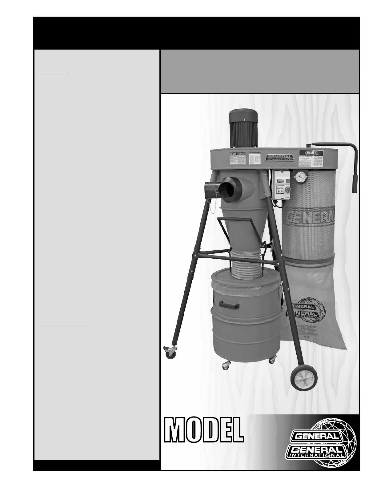
FEATURES
Simple design for easy maintenance.
Efficient collection and separation of large chips
which drop into the collection drum before
reaching the impeller.
Remote control for convenient operation from
virtually anywhere in the shop.
Equipped with an ultra efficient 1 micron canister filter with total surface area of 40.3 square
feet.
Canister filter equipped with crank handle/
internal shaker for easy filter cleaning without
removing bag.
Sturdy steel support frame and collection drum
both equipped with casters for complete mobility within the shop.
30 gallon chip collection drum included.
Special design quick-remove drum lid handle
mechanism for fast, tool-free drum cleaning.
PORTABLE DUST COLLECTOR
2 STAGE - 1 1/2 HP
SPECIFICATIONS
• Airflow capacity
778 cfm
• Blower wheel diameter
12 3/4" (323 mm)
• Sound rating
84 dB
• Inlet diameter
(1) 6" (152 mm)
(or 2) 4" (100 mm)
• Static pressure
8" of water
• Canister filter (dia x h)
14 1/2" x 23" (370 x 600 mm)
• Overall dimensions (l x w x h)
45 5/8" x 47 1/4" x 69 1/4" (1160 x 1200 x 1760 mm)
• Motor M1
1 1/2 HP, 110 V, 11 A
• Weight
156 lbs (71 kg)
Version #1_Revision #1 - March 2015
© Copyright General International
MODEL
#
10-805CF
Page 2

GENERAL® INTERNATIONAL
8360 Champ-d’Eau, Montreal (Quebec) Canada H1P 1Y3
Telephone (514) 326-1161 • Fax (514) 326-5555 • www.general.ca
THANK YOU
for choosing this General® International model 10-805CF
dust collector. This machine has been carefully tested and inspected before shipment and if
properly used and maintained, will provide you with years of reliable service. For your safety,
as well as to ensure optimum performance and trouble-free operation, and to get the most
from your investment, please take the time to read this manual before assembling, installing
and operating the unit.
The manual’s purpose is to familiarize you with the safe operation, basic function, and features
of this dust collector as well as the set-up, maintenance and identification of its parts and
components. This manual is not intended as a substitute for formal woodworking instruction,
nor to offer the user instruction in the craft of woodworking. If you are not sure about the safety
of performing a certain operation or procedure, do not proceed until you can confirm, from
knowledgeable and qualified sources, that it is safe to do so.
Once you’ve read through these instructions, keep this manual handy for future reference.
DISCLAIMER: The information and specifications
in this manual pertain to the unit as it was supplied
from the factory at the time of printing. Because we
are committed to making constant improvements,
General® International reserves the right to make
changes to components, parts or features of this unit
as deemed necessary, without prior notice and without
obligation to install any such changes on previously
delivered units. Reasonable care is taken at the factory
to ensure that the specifications and information in this
manual corresponds with that of the unit with which it
was supplied. However, special orders and “after factory”
modifications may render some or all information in
this manual inapplicable to your machine. Further, as
several generations of this model of dust collector and
several versions of this manual may be in circulation,
if you own an earlier or later version of this unit, this
manual may not depict your unit exactly. If you have
any doubts or questions contact your retailer or our
support line with the model and serial number of your
unit for clarification.
Page 3

GENERAL® INTERNATIONAL WARRANTY
All component parts of General® International and Excalibur by General International® products
are carefully inspected during all stages of production and each unit is thoroughly inspected upon
completion of assembly.
Limited Lifetime Warranty
Because of our commitment to quality and customer satisfaction, General® International agrees to
repair or replace any part or component which upon examination, proves to be defective in either
workmanship or material to the original purchaser for the life of the tool. However, the Limited Lifetime
Warranty does not cover any product used for professional or commercial production purposes nor
for industrial or educational applications. Such cases are covered by our Standard 2-year Limited
Warranty only. The Limited Lifetime Warranty is also subject to the “Conditions and Exceptions” as listed
below.
Standard 2-Year Limited Warranty
All products not covered by our lifetime warranty including products used in commercial, industrial
and educational applications are warranted for a period of 2 years (24 months) from the date of
purchase. General® International agrees to repair or replace any part or component which upon
examination, proves to be defective in either workmanship or material to the original purchaser during
this 2-year warranty period, subject to the “conditions and exceptions” as listed below.
To file a Claim
To file a claim under our Standard 2-year Limited Warranty or under our Limited Lifetime Warranty,
all defective parts, components or machinery must be returned freight or postage prepaid to
General® International, or to a nearby distributor, repair center or other location designated by
General® International. For further details call our service department at 1-888-949-1161 or your local
distributor for assistance when filing your claim.
Along with the return of the product being claimed for warranty, a copy of the original proof of purchase
and a “letter of claim” must be included (a warranty claim form can also be used and can be obtained,
upon request, from General® International or an authorized distributor) clearly stating the model and
serial number of the unit (if applicable) and including an explanation of the complaint or presumed
defect in material or workmanship.
CONDITIONS AND EXCEPTIONS:
This coverage is extended to the original purchaser only. Prior warranty registration is not required but
documented proof of purchase i.e. a copy of original sales invoice or receipt showing the date and
location of the purchase as well as the purchase price paid, must be provided at the time of claim.
Warranty does not include failures, breakage or defects deemed after inspection by
General® International to have been directly or indirectly caused by or resulting from; improper use,
or lack of or improper maintenance, misuse or abuse, negligence, accidents, damage in handling or
transport, or normal wear and tear of any generally considered consumable parts or components.
Repairs made without the written consent of General® International will void all warranty.
Page 4

TABLE OF CONTENTS
Rules for safe operation ..................................................................................................... 5
Electrical requirements ...................................................................................................... 6
Identification of main parts and components .................................................................. 7
Unpacking .......................................................................................................................... 8
Placement the within the shop .......................................................................................... 9
Assembly instructions ................................................................................................. 9 - 19
installing the upper cyclone separator on the impeller/separator ....................................................... 9 -10
Installing the legs ........................................................................................................................................ 10 -11
Installing the wheels and lockable swivel casters ........................................................................................ 11
Installing the switch box ................................................................................................................................... 12
Installing the pressure gauge .......................................................................................................................... 12
Installing the canister filter ........................................................................................................................ 13 - 14
Installing/Assembling the collection drum ............................................................................................ 14 - 18
Connecting the pressure gauge and drum to the impeller ................................................................. 18 -19
Installing the inlet fitting .................................................................................................................................... 19
Basic adjustments and controls ...................................................................................... 20
Connecting to a power source .......................................................................................................................20
Magnetic switch ................................................................................................................................................ 20
Overload protection ......................................................................................................................................... 20
Operating Instructions ..................................................................................................... 21
Checklist before starting .................................................................................................................................. 21
Maintenance .................................................................................................................... 21
Periodic maintenance ..................................................................................................................................... 21
Cleaning or replacing the canister filter ........................................................................................................ 21
Emptying the collector bag and drum .......................................................................................................... 22
Recommended optional accessories ............................................................................. 22
Parts list & diagram .................................................................................................. 23 - 25
Contact information ........................................................................................................ 26
Page 5

RULES FOR SAFE OPERATION
To help ensure safe operation, please take a moment to learn the machine’s applications and limitations,
as well as potential hazards. General
harmless for any injury that may result from the improper use of it’s equipment.
1. Do not operate the dust collector when tired,
distracted, or under the effects of drugs, alcohol or
any medication that impairs reflexes or alertness.
2. The work area should be well lit, clean and free
of debris.
3. Keep children and visitors at a safe distance when
the machine is in operation; do not permit them to
operate the dust collector .
4. Childproof and tamper proof your shop and all
machinery with locks, master electrical switches
and switch keys, to prevent unauthorized or unsu pervised use.
5. STAY ALERT! Give your work your undivided attention.
Even a momentary distraction can lead to serious
injury.
6. Fine particulate dust is a carcinogen that can be
hazardous to health. Work in a well-ventilated
area and whenever possible use a dust collector
and wear eye, ear and respiratory protection
devices.
7. Do not wear loose clothing, gloves, bracelets, neck laces or other jewelry while the dust collector is in
operation. Wear protective hair covering to contain
long hair and wear non-slip footwear.
8. Do not insert hands, fingers or any foreign objects
into ventilation inlet and outlet openings.
9. Do not operate this machine without either a filter
bag or filter cartridge properly installed on the unit.
10. Clean filters (bags on standard model or cartridges
on “CF” model) on a regular basis and replace as
needed.
11. Do not handle the electrical plug with wet hands.
12. Do not use this unit outdoors, or near wet surfaces.
®
International disclaims any real or implied warranty and holds itself
14. Do not vacuum anything that is burning, smoking
or smoldering such as cigarettes, matches or hot
ashes.
15. Do not vacuum or use this dust collector near flam mable or combustible liquids, gases, gasoline or
other fuels, lighter fluid, cleaners, oil or solvent
based paints, natural gas, hydrogen or explosive
dusts like coal dust, magnesium dust, grain dust or
gun powder.
16. Do not operate the unit until a dust hose is installed
onto the hose inlet.
17. Never leave the machine unattended while it is run ning or with the power on.
18. To avoid health hazards from vapors or dusts, do
not vacuum toxic material.
19. Use only recommended accessories. Use of acces
sories NOT recommended by General
may result in a risk of injury or damage to the ma chine.
20. Always disconnect the unit from the power source
before servicing, performing any maintenance or
repairs and when changing bags or hoses, or if the
machine will be left unattended.
21. Make sure that the switch is in the “OFF” position be fore plugging in the power cord.
22. Make sure the tool is properly grounded. If equip ped with a 3-prong plug, it should be used with
a three-pole receptacle. Never remove the third
prong.
23. Do not use this dust collector for any purpose other
than its intended use. If used for other purposes,
General
plied warranty and holds itself harmless for any
injury, which may result from that use.
®
International disclaims any real or im-
®
International
13. Always turn on the dust collector before starting
the dust producing machine. Always turn off the
dust producing machine before turning off the dust
collector.
5
Page 6
ELECTRICAL REQUIREMENTS
BEFORE CONNECTING THE MACHINE TO THE POWER SOURCE, VERIFY THAT THE VOLTAGE OF YOUR POWER
SUPPLY CORRESPONDS WITH THE VOLTAGE SPECIFIED ON THE MOTOR I.D. NAMEPLATE. A POWER SOURCE
WITH GREATER VOLTAGE THAN NEEDED CAN RESULT IN SERIOUS INJURY TO THE USER AS WELL AS DAMAGE
TO THE MACHINE. IF IN DOUBT, CONTACT A QUALIFIED ELECTRICIAN BEFORE CONNECTING TO THE POWER
SOURCE.
THIS TOOL IS FOR INDOOR USE ONLY. DO NOT EXPOSE TO RAIN OR USE IN WET OR DAMP LOCATIONS.
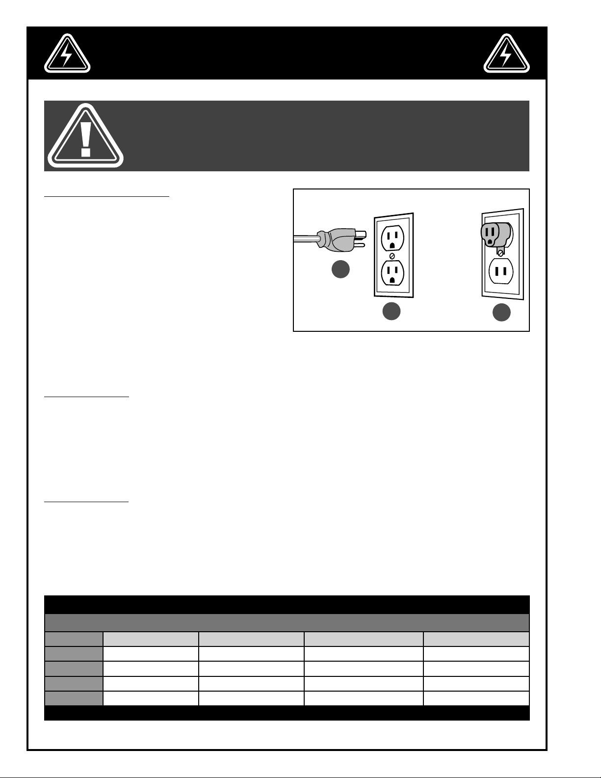
GROUNDING INSTRUCTIONS
In the event of an electrical malfunction or short circuit,
grounding reduces the risk of electric shock. The motor
of this machine is wired for 110 V single phase operation and is equipped with a 3-conductor cord and
a 3-prong grounding plug A to fit a grounded type
receptacle B. Do not remove the 3rd prong (grounding pin) to make it fit into an old 2-hole wall socket or
extension cord. If an adaptor plug is used C, it must be
attached to the metal screw of the receptacle.
Note: The use of an adaptor plug is illegal in some
areas. Check your local codes. If you have any
doubts or if the supplied plug does not correspond
to your electrical outlet, consult a qualified electrician before proceeding.
A
B
C
CIRCUIT CAPACITY
Make sure that the wires in your circuit are capable of handling the amperage draw from your machine, as well
as any other machines that could be operating on the same circuit. If you are unsure, consult a qualified electrician. If the circuit breaker trips or the fuse blows regularly, your machine may be operating on a circuit that is
close to its amperage draw capacity. However, if an unusual amperage draw does not exist and a power failure
still occurs, contact a qualified technician or our service department.
EXTENSION CORDS
If you find it necessary to use an extension cord with your machine, use only 3-wire extension cords that have
3-prong grounding plug and a matching 3-pole receptacle that accepts the tool’s plug. Repair or replace a damaged extension cord or plug immediately.
Make sure the cord rating is suitable for the amperage listed on the motor I.D. plate. An undersized cord will cause
a drop in line voltage resulting in loss of power and overheating. The accompanying chart shows the correct size
extension cord to be used based on cord length and motor I.D. plate amp rating. If in doubt, use the next heavier
gauge. The smaller the number, the heavier the gauge.
TABLE - MINIMUM GAUGE FOR CORD
EXTENSION CORD LENGTH
AMPERES 50 feet 100 feet 200 feet 300 feet
< 5
6 to 10
10 to 12
12 to 16
*NR = Not Recommended
18 16 16 14
18 16 14 12
16 16 14 12
14 12 *NR *NR
6
Page 7
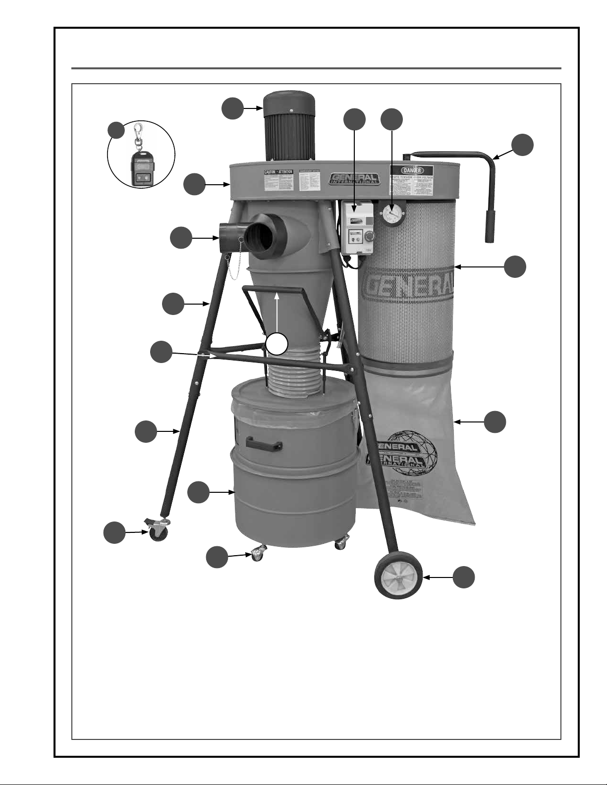
IDENTIFICATION OF MAIN PARTS AND COMPONENTS
H
I J
Q
K
G
F
L
E
D
C
P
B
A
A. SWIVEL CASTER
B. LOCKABLE SWIVEL CASTER
C. LOWER LEG
D. CROSS BRACE
E. UPPER LEG
F. 4" & 6" HOSE INLET
G. IMPELLER/SEPARATOR ASSEMBLY
H. MOTOR
I. ON/OFF MAGNETIC SWITCH
O
M
N
J. PRESSURE GAUGE
K. CANISTER FILTER HANDLE
L. CANISTER FILTER
M. COLLECTOR BAG
N. WHEEL
O. QUICK-REMOVE DRUM LID HANDLE
P. CHIP COLLECTION DRUM ASSEMBLY
Q. REMOTE CONTROLLER
7
Page 8
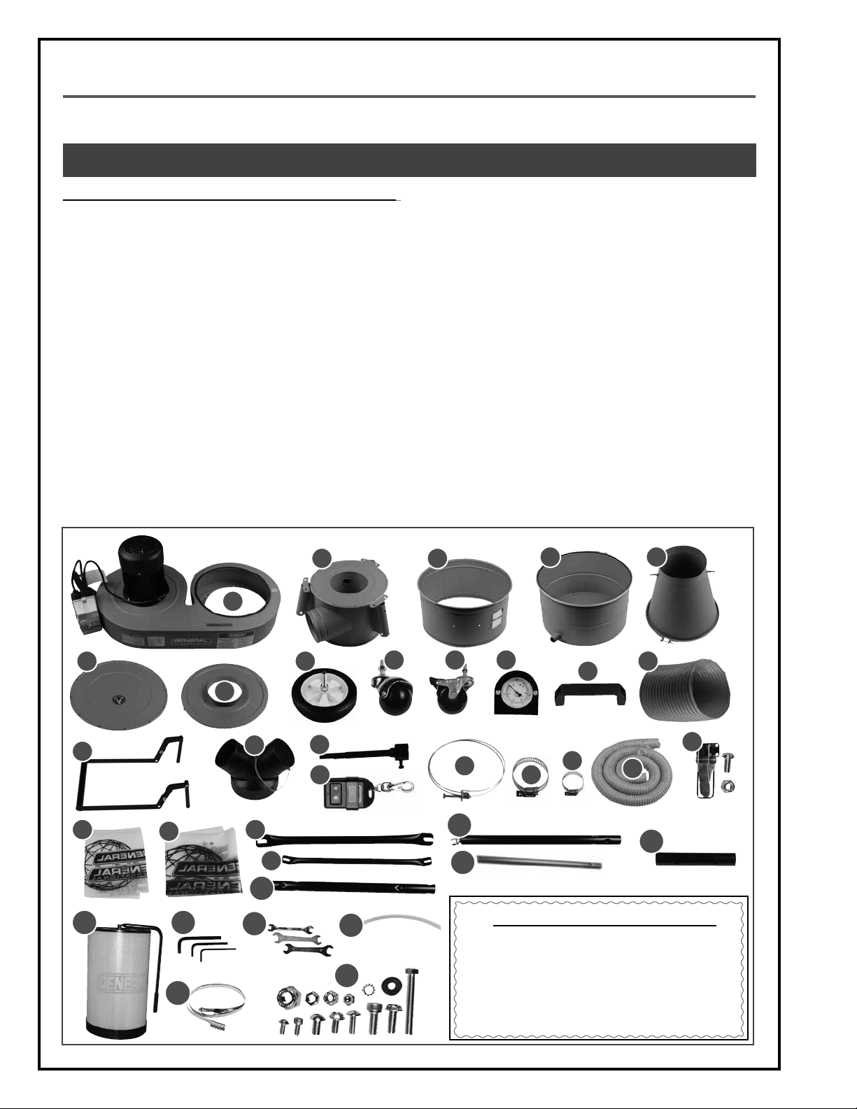
UNPACKING
Carefully unpack and remove the unit and its components from the box and check for missing or damaged items
as per the list of contents below.
NOTE: PLEASE REPORT ANY DAMAGED OR MISSING ITEMS TO YOUR GENERAL® INTERNATIONAL DISTRIBUTOR IMMEDIATELY.
LIST OF CONTENTS QTY
A. IMPELLER/SEPARATOR ASSEMBLY ...........................................1
B. UPPER CYCLONE SEPARATOR ................................................. 1
C. UPPER COLLECTION DRUM ..................................................... 1
D. LOWER COLLECTION DRUM ................................................... 1
E. LOWER CYCLONE SEPARATOR ................................................ 1
F. CANISTER LID ........................................................................... 1
G. COLLECTION DRUM LID .......................................................... 1
H. WHEEL ...................................................................................... 2
I. SWIVEL CASTER (DRUM) .......................................................... 4
J. LOCKABLE SWIVEL CASTER ..................................................... 1
K. PRESSURE GAUGE .................................................................... 1
L. COLLECTION DRUM HANDLE ................................................. 1
M. JUNCTION HOSE ...................................................................... 1
N. QUICK-REMOVE HANDLE ........................................................ 1
O. HOSE FITTING ........................................................................... 1
P. FILTER HANDLE MOUNT ARM .................................................. 1
Q. REMOTE CONTROLLER ............................................................ 1
R. HOSE CLAMP ........................................................................... 2
B C
S. HOSE CLAMP (LARGE) ............................................................ 2
T. HOSE CLAMP (SMALL) ............................................................ 2
U. DUST HOSE ............................................................................... 1
V. LATCH (WITH 8 SCREWS AND NYLOCK NUTS)........................ 2
W. COLLECTOR BAG ..................................................................... 1
X. DRUM LINER BAG .................................................................... 1
Y. CROSS BRACE (LONG) ........................................................... 2
Z. CROSS BRACE (SHORT) ........................................................... 1
AA. UPPER LEG ................................................................................ 3
AB. LOWER LEG (LONG) ................................................................ 2
AC. LOWER LEG (SHORT) ............................................................... 1
AD. CONNECTOR ........................................................................... 3
AE. CANISTER FILTER ...................................................................... 1
A F. 4, 5, 6 MM ALLEN KEY .............................................................. 1
AG. COMBINATION WRENCHES .................................................... 3
AH. PRESSURE GAUGE HOSE .......................................................... 1
AI. BAG CLAMP ............................................................................. 1
AJ. HARDWARE BAG ...................................................................... 1
D E
F
N
W
AE AF
X
AI
A
H
G
O
Y
Z
AA
AG
P
Q
AH
I J K
R
AB
AC
ADDITIONAL REQUIREMENTS FOR SET UP
L
T
S
M
V
U
AD
• Extra person for help with lifting
AJ
• 14 & 19 mm wrenches
• An adjustable wrench
• Phillips & flat head screwdrivers
8
Page 9

PLACEMENT WITHIN THE SHOP
LAYING OUT A PLAN FOR THE PIPING
For permanent installations, it is advisable to map out a rough layout of your planned installation starting from
the dust collector out to all the machines that you wish to connect to the system. You may vary your layout to suit
your specific shop needs and may choose to use metal or plastic ducting, or flexible hose in any combination as
suited to your needs.
Note: To avoid accidents as well as damage to ducting or hoses, plan your installation with hoses and ducting
running along walls or mounted from above wherever possible. See the accompanying examples of non-recommended
and recommended installations.
HOSES AND DUCTING RUNNING ALONG THE SHOP FLOOR BETWEEN MACHINERY CAN CAUSE USERS TO TRIP
AND LEAD TO SERIOUS INJURY.
Wherever possible avoid running hoses and ducting
along the floor.
Keep hoses and ducting safely mounted along the
walls.
ASSEMBLY INSTRUCTIONS
BEFORE ASSEMBLING, MAKE SURE THAT THE SWITCH IS IN THE “OFF” POSITION AND THAT THE POWER CORD IS
UNPLUGGED. DO NOT PLUG IN OR TURN ON THE MACHINE UNTIL YOU HAVE COMPLETED THE ASSEMBLY AND
INSTALLATION STEPS DESCRIBED IN THIS SECTION OF THE MANUAL.
INSTALLING THE UPPER CYCLONE SEPARATOR ON THE IMPELLER/SEPARATOR
1. With the help of an assistant, set the impeller/sepa-
rator upside down on a flat and stable surface.
2. Place the upper cyclone on the impeller and align
its mounting holes with the corresponding holes in
the impeller separator.
9
Page 10

BEFORE ASSEMBLING, MAKE SURE THAT THE SWITCH IS IN THE “OFF” POSITION AND THAT THE POWER CORD IS
UNPLUGGED. DO NOT PLUG IN OR TURN ON THE MACHINE UNTIL YOU HAVE COMPLETED THE ASSEMBLY AND
INSTALLATION STEPS DESCRIBED IN THIS SECTION OF THE MANUAL.
INSTALLING THE UPPER CYCLONE SEPARATOR ON THE IMPELLER/SEPARATOR (CONTINUED)
A
3. Attach the cyclone to the impeller using 12 cap
screws A and a 4 mm Allen key.
INSTALLING THE LEGS
B
4. Complete the assembly using 6 flange bolts B and
a 12 mm wrench.
C
1. Insert an upper leg into the 3 upper cylone mount-
ing brackets.
2. Align the leg mounting holes with the corresponding holes in the bracket, then secure each leg with
3 cap screws per leg C using a 5 mm Allen key.
D
F
E
3. Slide a connector onto each leg, align its mounting
holes with the corresponding holes in the leg, then
secure the connector with 3 cap screws D per connector using a 5 mm Allen key.
Note: Do not use the hole E, this hole is used for the cross
braces later.
4. Insert the short lower leg into F and the two other legs into the other connectors. Twist the legs to align their
mounting holes with the correponding holes in the leg connectors, making sure the legs are leveled, then
secure each leg with 4 cap screws per leg using a 5 mm Allen key.
10
Page 11

BEFORE ASSEMBLING, MAKE SURE THAT THE SWITCH IS IN THE “OFF” POSITION AND THAT THE POWER CORD IS
UNPLUGGED. DO NOT PLUG IN OR TURN ON THE MACHINE UNTIL YOU HAVE COMPLETED THE ASSEMBLY AND
INSTALLATION STEPS DESCRIBED IN THIS SECTION OF THE MANUAL.
INSTALLING THE LEGS (CONTINUED)
G
H
5. Align the cross brace mounting holes with the cor-
responding holes in the legs connetors.
INSTALLING THE WHEELS AND LOCKABLE SWIVEL CASTERS
1. Screw the wheel axles into their supports in the
end of the long lower legs.
6. Attach a cross brace by hand tightening a screw
G at each end. Repeat with the other cross braces,
then tighten all the screws with a 5 mm Allen key.
Note: The short cross brace can only be installed betwen
the closest two legs H.
A
2. Attach the wheels by tightening the nylock nut A
using a 19 mm wrench and an adjustable wrench.
B
3. Secure the wheels in the proper position by tightening
the jam nuts using two 14 mm wrenches.
4. Screw the lockable swivel caster with a sprocket
washer B into the short leg, then secure it in position by tightening the two jam nuts using two 14
mm wrenches.
11
Page 12

BEFORE ASSEMBLING, MAKE SURE THAT THE SWITCH IS IN THE “OFF” POSITION AND THAT THE POWER CORD IS
UNPLUGGED. DO NOT PLUG IN OR TURN ON THE MACHINE UNTIL YOU HAVE COMPLETED THE ASSEMBLY AND
INSTALLATION STEPS DESCRIBED IN THIS SECTION OF THE MANUAL.
INSTALLING THE SWITCH BOX
A
1. Align the switch bracket mounting holes with the
corresponding holes in the impeller.
2. Attach the switch box to the impeller with two cap
screws A using a 6 mm Allen key.
INSTALLING THE PRESSURE GAUGE
B
1. Using a 10 mm wrench remove the 2 flange bolts B. 2. Attach the pressure gauge to the impeller with the
flange bolts you just removed.
3. Slide a small hose clamp onto the end of the hose. 4. Slide the hose onto the gauge inlet, then tighten
the hose clamp using a flat screwdriver.
12
Page 13

BEFORE ASSEMBLING, MAKE SURE THAT THE SWITCH IS IN THE “OFF” POSITION AND THAT THE POWER CORD IS
UNPLUGGED. DO NOT PLUG IN OR TURN ON THE MACHINE UNTIL YOU HAVE COMPLETED THE ASSEMBLY AND
INSTALLATION STEPS DESCRIBED IN THIS SECTION OF THE MANUAL.
INSTALLING THE CANISTER FILTER
A
1. With the help of an assistant, turn the machine up-
right on a flat surface, then fit the canister against
the impeller.
2. Align the canister mounting holes with the corresponding holes in the impeller, then attach
the cansiter with 6 flange bolts A using a 12 mm
wrench.
B
3. Slide the mounting arm onto the canister shaft. 4. Secure the arm by tightening screws B using a 5
mm Allen key.
D
C
5. Place the canister lid on the impeller with the
mounting arm through the center hole. Align the
reference marks C.
6. Align the lid mounting holes with the corresponding holes in the impeller, then secure the lid by
starting with screws D on opposite sides.
13
Page 14

BEFORE ASSEMBLING, MAKE SURE THAT THE SWITCH IS IN THE “OFF” POSITION AND THAT THE POWER CORD IS
UNPLUGGED. DO NOT PLUG IN OR TURN ON THE MACHINE UNTIL YOU HAVE COMPLETED THE ASSEMBLY AND
INSTALLATION STEPS DESCRIBED IN THIS SECTION OF THE MANUAL.
INSTALLING THE CANISTER FILTER (CONTINUED)
E
7. Once all the screws are installed, tighten them all
the way for an airtight seal.
9. Fit the plastic collector bag over the bottom of the
canister filter.
ASSEMBLING/INSTALLING THE COLLECTION DRUM
8. Fit the handle onto the mounting arm, making
sure the bolt is aligned with the flat side of the arm.
Then secure it in place with the bolt E using a 10
mm wrench.
10. Use the belt clamp to hold the bag in place, making sure the metal strap is sitting in the groove on
the lower portion of the canister.
1. Set the lower drum upside down on a flat surface.
14
2. Screw the 4 swivel casters to their mounting holes.
Page 15

BEFORE ASSEMBLING, MAKE SURE THAT THE SWITCH IS IN THE “OFF” POSITION AND THAT THE POWER CORD IS
UNPLUGGED. DO NOT PLUG IN OR TURN ON THE MACHINE UNTIL YOU HAVE COMPLETED THE ASSEMBLY AND
INSTALLATION STEPS DESCRIBED IN THIS SECTION OF THE MANUAL.
ASSEMBLING/INSTALLING THE COLLECTION DRUM (CONTINUED)
3. Lock each swivel caster by tightening the jam nuts
with two 12 mm wrenches.
A
B
5. Set the upper drum on the lower drum, positioning
the window A opposite the tube B.
C
4. Remove the metal belt using a 10 mm wrench.
6. Slide the metal belt down over the top drum and
tighten it over the joint between the 2 drums to
hold them together.
7. Install the drum handle with phillips screws and
cap nuts C using a screwdriver and pliers.
D
8. Align the latch mounting holes with the holes in
the drum. Attach the 2 latches to the drum using
phillips screws with and nylock nuts inside the
drum D.
15
Page 16

BEFORE ASSEMBLING, MAKE SURE THAT THE SWITCH IS IN THE “OFF” POSITION AND THAT THE POWER CORD IS
UNPLUGGED. DO NOT PLUG IN OR TURN ON THE MACHINE UNTIL YOU HAVE COMPLETED THE ASSEMBLY AND
INSTALLATION STEPS DESCRIBED IN THIS SECTION OF THE MANUAL.
ASSEMBLING/INSTALLING THE COLLECTION DRUM (CONTINUED)
9. Install the liner bag (the bigger of the 2) inside the
drum.
E
Note: If needed, adjust the nuts and jam nuts E so that the
latches firmly close the lid.
E
10. Place the lid on the drum making sure the hooks
are aligned with the latches. Secure the drum lid
by clamping the latches.
11. Remove the lower cyclone separator metal belt
using a 10 mm wrench.
12. With the help of an assistant, hold the lower cyclone against the upper cyclone and tighten it
over the joint between the 2 sections to hold them
together using a 10 mm wrench.
16
13 Fit a hose clamp onto the junction hose, then slide
the hose onto the cyclone. Tighten the hose clamp
using a 10 mm wrench.
Page 17

BEFORE ASSEMBLING, MAKE SURE THAT THE SWITCH IS IN THE “OFF” POSITION AND THAT THE POWER CORD IS
UNPLUGGED. DO NOT PLUG IN OR TURN ON THE MACHINE UNTIL YOU HAVE COMPLETED THE ASSEMBLY AND
INSTALLATION STEPS DESCRIBED IN THIS SECTION OF THE MANUAL.
ASSEMBLING/INSTALLING THE COLLECTION DRUM (CONTINUED)
14. Place the drum against the junction hose to evalu-
ate if the hose needs to be cut. Make a reference
mark and cut as needed.
D
16. Verify that the junction hose has been cut to the
correct length by placing the drum under the lid.
Then remove the drum and detach the hose with
the lid from the cyclone by loosening the hose
clamp D.
15. Fit the other hose clamp onto the opposite end of
junction hose. Slide the fitting on the drum lid drum
lid into the junction hose, and tighten the hose
clamp.
E
F
17. Insert a bolt with a washer E into the 2 holes in the
lid. From the top of the lid install 2 nuts onto each
bolt F.
G
18. Hand tighten the bolts in the threaded ends of the
quick-remove handle draw bars G.
19. Pass the handle under and behind the front cross
brace. Slide the hose back onto the cyclone, then
tighten the hose clamp.
17
Page 18

BEFORE ASSEMBLING, MAKE SURE THAT THE SWITCH IS IN THE “OFF” POSITION AND THAT THE POWER CORD IS
UNPLUGGED. DO NOT PLUG IN OR TURN ON THE MACHINE UNTIL YOU HAVE COMPLETED THE ASSEMBLY AND
INSTALLATION STEPS DESCRIBED IN THIS SECTION OF THE MANUAL.
ASSEMBLING/INSTALLING THE DRUM COLLECTION (CONTINUED)
21. Spread the handle arms apart and slide them
onto the threaded rods as shown.
E
23. Adjust the height of the arms as needed, then tight-
en the nuts E as shown: one against the lid and the
other against the draw bar.
CONNECTING THE PRESSURE GAUGE TO THE DRUM
22. Lower the handle to lift the lid and confirm that
there is enough space between the lid and the
drum to remove the drum easily.
F
24. Once the handle is properly adjusted, lock it in
place by screwing a nylock nut F on each threaded rod.
Note: Do not overtight the nuts
1. Slide a small hose clamp onto the pressure gauge,
and slide the hose onto the fitting at the rear of the
impeller.
18
2. Using a Phillips screwdriver tighten the hose clamp.
Page 19

BEFORE ASSEMBLING, MAKE SURE THAT THE SWITCH IS IN THE “OFF” POSITION AND THAT THE POWER CORD IS
UNPLUGGED. DO NOT PLUG IN OR TURN ON THE MACHINE UNTIL YOU HAVE COMPLETED THE ASSEMBLY AND
INSTALLATION STEPS DESCRIBED IN THIS SECTION OF THE MANUAL.
CONNECTING THE PRESSURE GAUGE TO THE DRUM (CONTINUED)
3. Fit a hose clamp onto the dust hose, and slide the
hose onto the fitting. Tighten the hose clamp using
4. Repeat with the other end of the hose at the bottom of the drum.
a Phillips screwdriver.
INSTALLING THE INLET FITTING
C
1. Slide the hose fitting onto the inlet.
2. Align the holes A and attach the fitting using the
screw B.
Note: For maximum efficiency, a supplied cap should be
installed on any unused openings C.
BASIC ADJUSTMENTS & CONTROLS
B
A
TO REDUCE THE RISK OF SHOCK OR FIRE DO NOT OPERATE THE UNIT WITH A DAMAGED POWER CORD OR PLUG. REPLACE DAMAGED CORD OR PLUG IMMEDIATELY. TO AVOID UNEXPECTED OR UNINTENTIONAL START-UP, MAKE SURE
THE POWER SWITCH IS IN THE OFF POSITION BEFORE CONNECTING TO A POWER SOURCE.
CONNECTING TO A POWER SOURCE
Once the assembly steps have been completed, plug
the power cord into an appropriate outlet.
Refer back to the section entitled “Electrical Requirements” and make sure all requirements and grounding instructions are followed.
When operations have been completed unplug the
machine
from the power source.
SWITCH OFF
TO AVOID UNEXPECTED OR UNINTENTIONAL
START-UP, MAKE SURE THAT THE POWER SWITCH
IS IN THE OFF POSITION BEFORE CONNECTING
TO A POWER SOURCE.
19
Page 20

MAKE SURE THE MACHINE HAS BEEN TURNED OFF AND UNPLUGGED FROM THE POWER SOURCE BEFORE PERFORMING ANY MAINTENANCE OR ADJUSTMENTS.
MAGNETIC SWITCH
This machine is equipped with a magnetic safety
switch designed to protect the unit and the user from
power surges, power outages or unintentional start-up.
The switch assembly is equipped with a green “start”
button A, and a red “stop” button B.
Once the stop button has been pressed, the machine
can only be started by turning the button to the right
to release it.
The remote control C offers the exact same On/Off function as the magnetic switch, from virtually anywhere in
the shop within the line of sight of the machine.
OVERLOAD PROTECTION
A
B
C
The magnetic safety switch on this machine is equipped with an overload protection feature. To prevent an electrical overload from damaging the motor, in the event of a spike in line voltage or amperage draw, the internal
overload protector will automatically be tripped, thereby cutting off power to the motor.
Common causes of such overloads:
• Overworking the motor, thereby causing an increase in power consumption and a spike in amperage draw.
• An electrical extension cord that is too long or not the correct gauge of wire, which can also cause an increase in amperage draw. If an electric extension cord must be used, follow the instructions and refer to the
chart in the electrical requirements section at the beginning of this manual.
• Overworked circuit caused by operating on a circuit that is close to its amperage draw capacity. Make sure
the circuit being used is capable of handling the amperage draw from this machine as well as any other
electrical devices operating on the same circuit. If you are unsure, consult a qualified electrician.
To reset the overload protection switch after it has been tripped proceed as follows:
D
E
1. Loosen the two screws D with a Phillips screwdriver
until you can remove the switch cover.
20
2. Press on the button E to reset the overload protection. Re-install the cover and then retighten the two
screws D before starting the machine.
Page 21

OPERATING INSTRUCTIONS
CHECKLIST BEFORE STARTING
ALWAYS TURN ON THE DUST COLLECTOR BEFORE STARTING YOUR DUST PRODUCING MACHINE AND ALWAYS STOP THE
DUST PRODUCING MACHINE BEFORE TURNING OFF THE DUST COLLECTOR.
•
To minimize airborne dust make sure that all hoses, fittings and clamps are secure and airtight.
•
Never operate the machine without a canister filter and plastic collector bag properly installed.
•
For maximum system efficiency, make sure a cover is installed on any unused hose inlet openings.
Note: The sound level of this machine is rated at approximately 84 dB during operation. Make sure that adequate hearing protection is used and that the overall sound level within the work environment is taken into consideration.
MAINTENANCE
PERIODIC MAINTENANCE
• All bearings are sealed and permanently lubricated. No further lubrication is needed.
• Periodically inspect all hardware, fittings and fasteners that may have loosened due to vibration - retighten as
needed.
• Keep the outside of the unit clean and wipe off excessive dust or dirt with a dry rag.
• Clean the canister filter on a regular basis and replace as needed, if damaged or perforated.
• Periodically inspect inside all pipes, fittings, hoses, blast gates, and connectors for accumulated dust buildup or other obstructions and clean as needed. Remove sections and vacuum or manually remove debris as
needed.
• Check and if necessary replace all damaged parts or components.
• Do not operate with a damaged canister filter - replace damaged canister filter immediately.
• Periodically inspect the power cord and plug for damage. If necessary, replace the power cord and plug
at the first signs of visible damage.
• Use only recommended parts and accessories. The use of parts or accessories NOT recommended by
GENERAL® INTERNATIONAL may result in a risk of injury or damage to the machine.
CLEANING OR REPLACING THE CANISTER FILTER
TURN THE SWITCH TO THE "OFF" POSITION AND UNPLUG THE UNIT FROM THE POWER SOURCE BEFORE CLEANING OR
REPLACING CANISTER FILTER OR BEFORE PERFORMING ANY MAINTENANCE.
After a period of time depending on the frequency of use, the canister filter may become clogged and affect
airflow as well the overall efficiency of the unit. Should you notice a drop in the efficiency or performance or if the
pressure gauge indicates , it may be a sign that it is time to clean the filter.
Note: When the pressure gauge shows a higher than normal pressure, this indicates that the filter is becoming clogged
and requires cleaning.
A
For basic cleaning, turn off and unplug the machine,
then simply rotate the handle on the canister A several
rotations. The internal flaps will rub against the corrugated inner filter and shake free any built-up dust from
inside the filter.
For a more thorough cleaning, after rotating the handle,
detach the canister and place it on the ground. Vacuum the inside of the canister to remove any remaining
dust from inside. Re-attach the canister and re-install its
collector bag.
21
Page 22

MAKE SURE THE MACHINE HAS BEEN TURNED OFF AND UNPLUGGED FROM THE POWER SOURCE BEFORE PERFORMING ANY MAINTENANCE OR ADJUSTMENTS.
EMPTYING THE COLLECTOR BAG & DRUM
Note: Depending on your needs, shop situation and local
regulations collections bags can be emptied and re-used
or disposed of (with their contents) and replaced with a
new bag.
1. Turn off and unplug the machine.
2. Unclip the bag clamp A and remove the collector
bag. Open the drum latches, lower the quick-remove handle and roll the drum out from beneath
the machine B.
Note: The reference line on the drum window indicates
when the maximum chip level has been reached.
3. Empty the bags in an appropriate container or
dispose of the bags making sure to comply with
all local codes and regulations regarding waste
disposal.
4. Re-install the emptied bags or install new bags as
needed.
A
B
RECOMMENDED OPTIONAL ACCESSORIES
Here is a sampling of optional accessories available from your local General International dealer that can be
used with this product. For more information about our products, please visit our website at www.general.ca
Item #10805-14
BAGS CLAMP
Cast-iron bag clamp for
model 10-805.
Item #10-807
CANISTER FILTER
1 micron canister filter.
Item #10-827
COLLECTOR BAG
For drum.
Item #10-140
DUST HOSES
6" X 50' heavy-duty flexible polyethylene.
Item #10-837
COLLECTOR BAG
For canister.
22
Item #10-089/#10-091
HOSE CLAMP
For 4" or 6" dust collector
hose.
Item #10-130/410
DUST HOSES
Heavy-duty flexible polyethylene. 10-130: 4" X 50';
10-410: 4" X 10'
Page 23

DIAGRAM
10-805CF
81
94
94
60
27
4
61
39
15
62
16
92 87
92
84
85
92
86
87
67
95
96
67
63
17
5
23
18
13
92
92
85
86
92
95
96
26
80
22
67
7
49
33
19
36
41
77
40
44
42
57
40
56
79
29
79
21
36
35
54
55
88
89
93
45
55
50
64
32
45
31
12
28
59
65
91
9
20
53
41
42
20
21
66
14
6
90
36
52
74
1
38
68
34
2
58
83
69
8
70
72
72
11
51
3
82
43
52
75
50
64
32
30
46
44
44
43
43
52
48
43
45
31
48
49
49
43
50
64
32
46
45
52
62
25
24
26
8024
22
12
33
43
75
48
83
76
71
73
10
58
78
42
41
37
76
47
20
44
23
Page 24

PARTS LIST
10-805CF
IMPORTANT: When ordering replacement parts, always give the model number, serial number of the
machine and part number. Also a brief description of each item and quantity desired.
PART # DESCRIPTION SPECIFICATIONS QTY
10805-01 MOTOR 1
10805-02 IMPELLER/SEPARATOR COVER 1
10805-03 ALUMINUM IMPELLER 12 3/4" 1
10805-04 LOWER CYCLONE SEPARATOR 1
10805-05 DRUM LINER BAG (ITEM #10-827) 1
10805-06 COLLECTOR BAG (CANISTER) (ITEM #10-837) 1
10805-07 SWIVEL CASTER 2" X 5/16" 1
10805-08 HOSE CLAMP Ø 347 1
10805-09 HOSE 1 1/2" X 1.8M 1
10805-10 SWITCH MOUNTING PLATE 1
10805-11 MAGNETIC SWITCH 1
10805-12 HOSE CLAMP 1 1/2" 2
10805-13 HOSE Y-FITTING 6" X 4 X 2" 1
10805-14 BAG CLAMP Ø 370 1
10805-15 PLASTIC HANDLE 1
10805-16 SQUARE PAD 1
10805-17 WINDOW 1
10805-18 INLET CAP 4" 1
10805-19 LOWER FIXING PLATE 1
10805-20 FLAP 3
10805-21 CANISTER FIXING PLATE 2
10805-22 FLANGE NUT 1/4" 8
10805-23 LOWER DRUM 1
10805-24 HOSE CLAMP Ø 525 1
10805-25 UPPER DRUM 1
10805-26 HEX HEAD BOLT 1/4" X 2 1/2" 2
10805-27 RIVET 4-2 8
10805-28 1 MICRON CANISTER FILTER (ITEM #10-807) 1
10805-29 CANISTER LID 1
10805-30 LOCKABLE SWIVEL CASTER 3" X 3/8" 1
10805-31 WHEEL MOUNTING BOLT 2
10805-32 NUT 3/8” 3
10805-33 WHEEL 7" 2
10805-34 O-RING 3
10805-35 KEY 7 X 7 X 25 1
10805-36 BEARING 3
10805-37 CAP SCREW M6 X 30 MM 1
10805-38 MOTOR CORD 1
10805-39 PHILLIPS HEAD SCREW 1/4" X 5/8" 2
10805-40 PHILLIPS HEAD SCREW M5 X 10 6
10805-41 FLAT WASHER 1/4” X 18 6
10805-42 HEX HEAD BOLT M6 7
10805-43 CAP SCREW 5/16" X 1/2" 33
10805-44 WASHER 1/2" X 19MM 4
10805-45 NYLOCK NUT 1/2" 4
10805-46 HEX HEAD BOLT 1/2" X 4" 2
10805-47 UPPER CYCLONE SEPARATOR 1
10805-48 UPPER LEG 3
24
Page 25

PARTS LIST
10-805CF
IMPORTANT: When ordering replacement parts, always give the model number, serial number of the
machine and part number. Also a brief description of each item and quantity desired.
PART # DESCRIPTION SPECIFICATIONS QTY
10805-49 CONNECTOR 3
10805-50 LOWER LEG (2 LONG LEGS +1 SHORT LEG) 3
10805-51 POWER CORD W/ PLUG 1
10805-52 CAP SCREW 3/16" X 3/8" 25
10805-53 SPINDLE 1
10805-54 FILTER HANDLE MOUNT ARM 1
10805-55 CAP SCREW M6 X 12MM 2
10805-56 BEARING FIXING PLATE 1
10805-57 HEX HEAD BOLT M6" X 16 1
10805-58 FLANGE BOLT 5/16" X 3/4" 8
10805-59 NUT M5 4
10805-60 DRUM LID 1
10805-61 CAP NUT 1/4" 2
10805-62 PHILLIPS HEAD SCREW M4 X 8MM 8
10805-63 LOCK NUT M4 11
10805-64 SPROCKET WASHER 3/8" 3
10805-65 FIXING PLATE 2
10805-66 PHILLIPS HEAD SCREW M5 X 15 4
10805-67 NUT 5/16" 4
10805-68 HEX HEAD BOLT 5/16" X 3/4" 4
10805-69 PRESSURE GAUGE FIXING PLATE 1
10805-70 PRESSURE GAUGE FRAME 1
10805-71 PRESSURE GAUGE 1
10805-72 CAP SCREW 1/4” X 3/4” 2
10805-73 NUT 1/4" 4
10805-74 CAP NUT 5/16" 4
10805-75 LONG CROSS BRACE 520 MM 2
10805-76 HOSE CLAMP 3/4" 2
10805-77 SHORT CROSS BRACE 410 MM 1
10805-78 LOCK WASHER M6 1
10805-79 RUBBER PACKING 2
10805-80 FLAT WASHER 2
10805-81 CENTRAL CONNECTION HOSE 8” 1
10805-82 IMPELLER WASHER 1
10805-83 FLANGE BOLT 1/4” X 1/2” 1
10805-84 QUICK-REMOVE DRUM LID HANDLE 1
10805-85 CONNECTING ARM 2
10805-86 DRAW BAR 2
10805-87 CAP SCREW 5/16" X 1/2" 4
10805-88 CANISTER HANDLE 1
10805-89 FOAM HANDLE 1
10805-90 BUSHING 1
10805-91 CLEAR HOSE 1/2” 1
10805-92 NYLOCK NUT 5/16” 6
10805-93 END CAP 1” 1
10805-94 HOSE CLAMP 8” 2
10805-95 FLAT WASHER 5/16” 2
10805-96 HEX HEAD BOLT 5/16” X 2” 2
25
Page 26

8360 Champ-d’Eau, Montreal (Quebec) Canada H1P 1Y3
Tel.: (514) 326-1161
Fax: (514) 326-5565 - Parts & Service / (514) 326-5555 - Order Desk
orderdesk@general.ca
www.general.ca
Follow us:
 Loading...