

Page 1
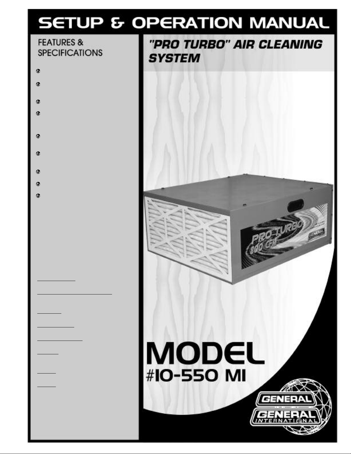
Cleans quickly and quietly to improve
workshop air quality.
Filters up to 98% of 5 micron airborne
particles and up to 85% of 1 micron
particles.
All steel construction with a durable
powder coated finish.
Superior 2 stage filtration system includes
a disposable, pleated outer filter and a
3 pocket inner filter. No tools required for
filter changes.
Includes filter cleaning sensor with indicator light. No more guessing if filter needs
cleaning.
Select between continuous run or timer
operation, including 1-15 hour timer run
settings in 1 hour increments.
Will not affect ambient room
temperature.
Includes 4 top mounted eye-bolts for
ceiling installation.
Remote control for convenient operation
(AAA batteries sold separately).
AIR MOVEMENT
800 CFM
FILTER CYCLE (20 TIMES/HOUR)
15’ x 20’ x 8’ ROOM
(4.5 x 6 x 2.44 m)
AIR SPEED
16.6 FT/SEC (5 M/SEC)
TIMER SETTINGS
1 TO 15 HOURS
REMOTE CONTROL
ON/OFF, TIMER
UNIT SIZE
28” x 24” x 12”
(710 x 610 x 310 mm)
MOTOR
1/8 HP, 110 V, 2.6 A
WEIGHT
68 LBS (31 KG)
VERSION #2, REVISION #1 (13448909)
© Copyright General International 02/2009
Page 2

GENERAL® INTERNATIONAL
8360 Champ-d’Eau, Montreal (Quebec) Canada H1P 1Y3
Telephone (514) 326-1161 • Fax (514) 326-5555 • www.general.ca
THANK YOU for choosing this General® International model 10-550“PRO TURBO”
air cleaning system. This air cleaning system has been carefully tested and inspected before
shipment and if properly used and maintained, will provide you with years of reliable service.
To ensure optimum performance and trouble-free operation, and to get the most from your
investment, please take the time to read this manual before assembling, installing and operating the unit.
The manual’s purpose is to familiarize you with the safe operation, basic function, and features
of this air cleaning system as well as the set-up, maintenance and identification of its
parts and components. This manual is not intended as a substitute for formal woodworking
instruction, nor to offer the user instruction in the craft of woodworking. If you are not sure about
the safety of performing a certain operation or procedure, do not proceed until you can
confirm, from knowledgeable and qualified sources, that it is safe to do so.
Once you’ve read through these instructions, keep this manual handy for future reference.
Disclaimer: The information and specifications in this
manual pertain to the unit as it was supplied from the
factory at the time of printing. Because we are committed
to making constant improvements, General
nal reserves the right to make changes to components,
parts or features of this unit as deemed necessary, without prior notice and without obligation to install any
such changes on previously delivered units. Reasonable
care is taken at the factory to ensure that the specifications and information in this manual corresponds with
®
Internatio-
that of the unit with which it was supplied. However, special orders and “after factory” modifications may render
some or all information in this manual inapplicable to
your machine. Further, as several generations of this
model of air cleaning and several versions of this manual may be in circulation, if you own an earlier or later
version of this unit, this manual may not depict your
machine exactly. If you have any doubts or questions
contact your retailer or our support line with the model
and serial number of your unit for clarification.
Page 3
GENERAL®& GENERAL®INTERNATIONAL WARRANTY
ll component parts of General®, General® International and Excalibur by General International
A
® products are carefully inspected during all stages of production and each unit is thoroughly
inspected upon completion of assembly.
Limited Lifetime Warranty
Because of our commitment to quality and customer satisfaction, General® and General®
International agree to repair or replace any part or component which upon examination,
proves to be defective in either workmanship or material to the original purchaser for the life
of the tool. However, the Limited Lifetime Warranty does not cover any product used for pro-
fessionnal or commercial production purposes nor for industrial or educational applications.
Such cases are covered by our Standard 2-year Limited Warranty only. The Limited Lifetime
Warranty is also subject to the “Conditions and Exceptions” as listed below.
Standard 2-Year Limited Warranty
All products not covered by our lifetime warranty including products used in commercial,
industrial and educational applications are warranted for a period of 2 years (24 months) from
the date of purchase. General® and General® International agree to repair or replace any
part or component which upon examination, proves to be defective in either workmanship or
material to the original purchaser during this 2-year warranty period, subject to the “conditions
and exceptions” as listed below.
To file a Claim
To file a claim under our Standard 2-year Limited Warranty or under our Limited Lifetime
Warranty, all defective parts, components or machinery must be returned freight or postage
prepaid to General® International, or to a nearby distributor, repair center or other location
designated by General® International. For further details call our service department at 1-888949-1161 or your local distributor for assistance when filing your claim.
Along with the return of the product being claimed for warranty, a copy of the original proof
of purchase and a “letter of claim” must be included (a warranty claim form can also be used
and can be obtained, upon request, from General® International or an authorized distributor)
clearly stating the model and serial number of the unit (if applicable) and including an explanation of the complaint or presumed defect in material or workmanship.
CONDITIONS AND EXCEPTIONS:
This coverage is extended to the original purchaser only. Prior warranty registration is not
required but documented proof of purchase i.e. a copy of original sales invoice or receipt
showing the date and location of the purchase as well as the purchase price paid, must be
provided at the time of claim.
Warranty does not include failures, breakage or defects deemed after inspection by General®
or General® International to have been directly or indirectly caused by or resulting from;
improper use, or lack of or improper maintenance, misuse or abuse, negligence, accidents,
damage in handling or transport, or normal wear and tear of any generally considered consumable parts or components.
Repairs made without the written consent of General® Internationallwill void all warranty.
Page 4

Rules for Safe Operation
To help ensure safe operation, please take a moment to learn the machine’s applications and limita-
ions, as well as potential hazards. General® International disclaims any real or implied warranty and
t
holds itself harmless for any injury that may result from improper use of its equipment.
1. READ and UNDERSTAND this instruction manual before
operating this air cleaner.
2. Keep the work area well lit, clean and free of debris or
clutter.
3. There is a high-speed blower wheel inside the cabinet
which can cause serious bodily harm. DO NOT insert
fingers or any foreign object into the blower housing.
4. Childproof and tamper proof your shop and all
machinery with locks, master electrical switches, and
switch keys to prevent unauthorized or unsupervised
use.
5. Do not obstruct any of the openings on the air
cleaner.
6. Do not wear loose clothing, gloves, bracelets, neck-
laces, or other jewlery.
7. Make sure the Outer Pleated Filter and Inner 3-Pouch
Filter have been installed before operating the
machine.
8. Do not use this air cleaning system near flammable or
combustible liquids, gases, gasoline or other fuels,
lighter fluid, cleaners, oil-based paints, natural gas,
hydrogen or explosive dusts like coal dust, magnesium dust, grain dust or gun powder.
9. Fine particulate dust is a carcinogen that can be haz-
ardous to health. Work in a well ventilated area and
wear eye, ear, and respiratory protection devices.
10. Do not expose to rain or use on or near wet surfaces.
This machine is for indoor use only and is intended for
dry pick-up only.
12. Do not handle the power cord, plug, or switches with
wet hands.
13. Follow all local electrical and safety codes.
14. Make sure the switch is in the “OFF” position before
plugging or unplugging the power cord.
15. Always turn off and unplug the machine from the
power source before servicing and/or when changing filters. Do not unplug by pulling on the cord,
always grasp the plug and not the cord.
16. Clean filters on a regular basis and replace as
needed.
17. Use only recommended accessories. Use of acce-
®
sories NOT recommended by General
may result in a risk of injury or damage to the
machine.
18. Protect the power cord and never allow the cord to
come in contact with sharp objects, hot surfaces, oil,
grease, or chemicals.
19. Replace or repair damaged or worn cord/wire immediately. All electrical connections, wiring, and repairs
should be performed by a qualified technician only.
20. Make sure the unit is properly grounded, if equipped
with a three-prong plug, plug into a three-pole electrical receptacle. Never remove the third prong.
21. Do not use this air cleaning system for anything other
than its intended use. If used for other purposes,
®
General
warranty and holds itself harmless for any injury, which
may result from that use.
International disclaims any real or implied
International
11. To avoid health hazards from vapors or dusts, do not
vacuum toxic material.
Page 5

ELECTRICAL REQUIREMENTS
BEFORE CONNECTING THE AIR FILTRATION SYSTEM TO THE POWER SOURCE CHECK THAT THE
SUPPLIED VOLTAGE CORRESPONDS TO THAT
SPECIFIED ON THE NAMEPLATE OF THE MACHINE.
A POWER SOURCE WITH GREATER VOLTAGE
HAN NEEDED CAN RESULT IN SERIOUS INJURY
T
TO THE USER AS WELL AS DAMAGE THE MACHINE.
IF IN DOUBT, CONTACT A QUALIFIED ELECTRICIAN BEFORE CONNECTING TO THE POWER
SOURCE.
GROUNDING INSTRUCTIONS
IN THE EVENT OF A MALFUNCTION OR BREAKDOWN,
grounding provides a path of least resistance for electric current and reduces the risk of electric shock. This
tool is equipped with an electric cord that has an
equipment-grounding conductor and a grounding
plug. The plug MUST be plugged into a matching
receptacle that is properly installed and grounded in
accordance with ALL local codes ad ordinances.
In all cases, make certain the receptacle is properly grounded. If you are not sure, have a qualified electrician check the receptacle.
This machine is for indoor use only. Do not expose
to rain or use in damp locations.
DO NOT MODIFY THE PLUG PROVIDED.
If it will not fit the receptacle, have the proper receptacle installed by a qualified electrician.
This tool is intended for use on a circuit that has a receptacle like the one illustrated in Figure . Figure
shows a 3-prong electrical plug and receptacle that
has a grounding conductor. If a properly grounded
receptacle is not available, an adapter (Figure ) can
be used to temporarily connect this plug to a 2-contact
grounded receptacle. The temporary adapter should
be used only until a properly grounded receptacle can
be installed by a qualified technician. The adapter
(Figure ) has a rigid lug extending from it that MUST
be connected to a permanent ground, such as a properly grounded receptacle box. The Canadian Electrical Code prohibits the use of these adapters.
IMPROPER CONNECTION of the equipment-grounding
conductor can result in risk of electric shock. The conductor with green insulation (with or without yellow
stripes) is the equipment-grounding conductor. If repair
or replacement of the electric cord or plug is necessary, DO NOT connect the equipment-grounding conductor to a live terminal.
This machine must be grounded while in use to
protect the operator from electrical shock.
CHECK with a qualified electrician or service person if
you do not completely understand the grounding
instructions or if you are not sure the tool is properly
grounded.
EXTENSION CORDS
If an extension cord is used, use only 3-wire extension
cords which have 3-prong grounding type plugs and
matching receptable which will accept the machine’s
plug.
5
Page 6

“PRO TURBO” AIR CLEANING SYSTEM
10-550
UNPACKING & SET-UP
FOR YOUR OWN SAFETY, DO NOT CONNECT THE
MACHINE TO A POWER SOURCE UNTIL YOU HAVE
READ AND UNDERSTOOD THIS MANUAL AND ALL
SAFETY AND OPERATING INSTRUCTIONS.
Note: For ceiling mount installation, extra hardware
such as mounting hooks, rope, or chain (not included)
may be required.
UNPACKING
Carefully unpack and remove the unit and its components from the box and check for missing or damaged
items as per the list of contents below.
Note: Report any missing or damaged items to your
General International distributor immediately.
ADDITIONAL REQUIREMENTS FOR SET-UP
• Adjustable Wrench
• Large Flat-Head Screw Driver
• Extra Person for Help with Lifting
LIST OF CONTENTS
QTY
AIR CLEANER . . . . . . . . . . . . . . . . . . . . . . . . . . . . .1
RUBBER FEET . . . . . . . . . . . . . . . . . . . . . . . . . . . . .4
5/16 - 18 FLANGE NUTS . . . . . . . . . . . . . . . . . . . .4
5/16 - 18 x 1 1/2” EYE-BOLTS . . . . . . . . . . . . . . . .4
REMOTE CONTROL (REQUIRES 2 AAA BATTERIES - NOT SUPPLIED) .1
BASIC FUNCTIONS OF THIS UNIT
The model 10-550 “PRO TURBO”air cleaner is designed to quietly and efficiently filter non-metallic airborne dust particles in the workshop. This unit is not a woodworking dust collector, but when used in conjunction with an adequate
and properly connected dust collector, this air cleaner can help to reduce the risks and health hazards associated
with airborne dust particles in the workshop and contribute to a cleaner, safer work environment for the user.
6
Page 7

This machine is not designed to function as a replacement for a woodworking dust collector. A woodworking dust
collector is connected, normally via a dust hose, to woodworking machinery and draws sawdust and woodchips
directly from the source (such as a blade, bit or cutting tool) – this is a different and separate operation from the
ne performed by this machine.
o
THIS UNIT IS NOT DESIGNED TO REPLACE PERSONAL BREATHING PROTECTION DEVICES SUCH AS RESPIRATORS OR
DUST MASKS.
TO ENSURE YOUR PERSONAL PROTECTION YOU MUST CONTINUE TO USE PERSONAL BREATHING PROTECTION
DEVICES WHENEVER RECOMMENDED FOR THE OPERATION OR WORK BEING PERFORMED.
The 2-stage filtration system includes a high efficiency inner 3-pouch filter that can capture up to 85% of airborne
dust particles as small as 1 micron, and an outer pleated filter that can capture up to 98% of airborne dust particles
as small as 5 microns.
With a rated air movement capacity of 800 cubic feet per minute this unit will re-circulate and filter all of the air in
a 15’ x 20’ x 8’ room up to 20 times per hour.
THE 10-550 PRO TURBO AIR CLEANER IS DESIGNED TO CAPTURE SOLID, DRY, NON-METALLIC AIRBORNE DUST PARTICLES ONLY. IT IS NOT DESIGNED (AND CANNOT BE RETRO-FITTED) TO FILTER OR PROTECT THE USER FROM PAINT
FUMES OR OVERSPRAY, NOXIOUS, HAZARDOUS, OR HARMFUL CHEMICAL FUMES, VOLATILE ORGANIC COMPOUNDS
(V.O.C’S), OR FOUL, UNPLEASANT OR HARMFUL ORDERS.
Featuring continuous run or timer operation, including 1-15 hour timer settings, the unit can be programmed to run
and continue to filter dust particles that are suspended in the ambient air in the workshop for up to 15 hours (in
1 hour increments), after you have completed your work in the shop.
The 10-550 Pro Turbo air cleaner can be either ceiling mounted (additional hardware may be required) or set on a
table, workbench or floor.
PREPARATION & INSTALLATION BEFORE USING
CARRYING & HANDLING THE UNIT
The air cleaner weighs 68 LBS (approximately 31 kg) and can
be carried using the two lifting handles inset on the sides of the
cabinet.
Whenever lifting or carrying the air cleaner, do so with the filters
positioned away from the body to avoid damaging the filters
through unintentional contact with belt buckles and zippers.
REMOVING THE STYROFOAM BLOCKS
To help protect the interior components from damage during
transportation, styrofoam blocks were inserted at the factory,
above and below the fan housing inside of the cabinet.
BEFORE PLUGGING IN AND USING THE AIR CLEANER THESE
STYROFOAM BLOCKS MUST
BE REMOVED.
Handle
Fig. 1
Fig. 2
7
Page 8

FAILURE TO REMOVE THE STYROFOAM BLOCKS MAY CAUSE DAMAGE TO THE MACHINE AND/OR BODILY HARM.
1. Make sure the air cleaner is not connected to a power
source.
2. Remove the Outer “Pleated” Filter by slightly lifting then pul-
ling the filter out at an angle. (Fig. 3)
Do the same for the Inner “Three Pouch” Filter.
3. Remove the two styrofoam blocks. (Fig. 4)
4. Reinstall the the Inner “Three Pouch” Filter making sure
pouches are pointing towards the FRONT
trol panel) of the air cleaner.
Do the same with the Outer “Pleated” Filter; make sure to
install the filter with the airflow arrow pointing towards the
FRONT
(Fig. 3.1)
(towards the control panel) of the air cleaner.
(torwards the con-
Fig. 3
1. Lift up.
2
1
2. Angle and
pull down.
Fig. 3.1
Fig. 4
INSTALLING THE RUBBER FEET
If you plan to use this unit on a flat surface (floor, table, workbench etc…), rather than ceiling mounted, the 4 supplied
foam-rubber feet will help absorb vibration and reduce noise.
1. Carefully place the air cleaner upside down on a solid flat
surface.
2. Peel off the adhesive backing and apply one rubber foot to
each corner on the underside of the machine. (Fig. 5.1)
3. Set the air cleaner on a flat stable surface with at least 3 FT
(1 m) of unobstructed clearance front and back to allow
for adequate airflow. (Fig. 5)
OVERHEAD / CEILING MOUNT INSTALLATION
THE AIR CLEANER WEIGHS 68 LBS (APPROXIMATELY 31 KG),
FOR OVERHEAD/CEILING MOUNTING MAKE SURE THAT THE
MOUNTING SURFACE IS ADEQUATE AND CAN FULLY SUPPORT THE WEIGHT. NEVER MOUNT THE AIR CLEANER TO
DRYWALL, SUSPENDED CEILING TILES, OR NON-STRUCTURAL
MEMBERS.
Fig. 5
Front
Rear
3 FT
Fig. 5.1
3 FT
ATTACHING THE EYEBOLTS TO THE AIR CLEANER
1. Unscrew the 4 screws installed on the top of the cabinet.
(Fig. 6)
2. Thread a flange nut onto each of the eye-bolts as shown. (Fig. 7)
8
Fig. 6 Fig. 7 Fig. 7.1
Page 9

3. Screw an eye-bolt into each of the threaded holes in the top
f the cabinet. Make sure the eye-bolts are threaded at least
o
eight complete turns into the air cleaner.
4. Tighten the flange nuts down against the top of the cabinet
as shown in Fig. 7.1.
5. Hang overhead or to the ceiling. An example of a typical
ceiling mount installation is shown in Fig. 8. Always use
mounting hardware that has a rated weight capacity of at
least 3 times the weight of the machine (68 LBS) and ensure
that any mounting hooks or fasteners that are used are properly secured to a structural member such as a beam or
joist.
Note: Make sure to always tighten the flange nuts down against the
surface of the air cleaner after making any height adjustments.
Note: Check the eyebolts and/or flange nuts periodically to make
sure they have not loosened. If so, retighten the eyebolts and/or
flange nuts.
OPERATION
Fig. 8
Ceiling Joist
or Beam
Ceiling
Threaded
Mounting Hook
or Threaded
Eye-Bolt
Chain or Rope
NEVER OPERATE THE AIR CLEANER UNLESS BOTH AIR FILTERS ARE PROPERLY INSTALLED IN THE MACHINE.
Note: During initial operation the air cleaner may produce a slight odor which will dissipate after a few hours of use.
OPERATING THE INLINE ON/OFF SWITCH
The unit is equipped with an inline ON/Off switch located on the
power cord (Fig #9). To allow electrical current to flow into the
machine, plug in the power cord to an appropriate outlet, and
press the inline switch to the “On” position. Note: If desired, with
the switch on the main control panel (Fig #10) in the “On” position you can start or stop the machine by using the inline switch
on the power cord.
Fig. 9
OPERATING THE CONTROL PANEL
With the unit plugged into an appropriate outlet and the inline switch on the power cord (Fig #9) in the “On” position, the power indicator light “PWR” (Fig. #10 – ) will light up, indicating the electrical current is flowing into the
machine.
The main On/Off button (Fig. #10 – ) on the control panel is used to turn the air cleaner on or off. When the unit is
on, the “Run” indicator (Fig. #10 – ) will also light up.
With the unit turned on in “Run” mode, pressing the “Timer” button (fig. #10 – ) activates the timer.
Note: the timer feature can only be activated when the unit is
turned on with the “Run” indicator lit. When the “Timer” button is
pressed once, the air cleaner will run for 1 hour. You can increase
the programmed run time, in 1 hour increments, with each successive push on the timer button.
When operating in timer mode, the appropriate timer indicator
light, or combination of lights, (Fig. #10 – ) will light up to show
the total number of hours for which the machine is set to run. The
machine will automatically stop running at the end of this programmed time period.
If desired, to cancel the timer setting before the completion of
the programmed time period, simply turn the unit off, using
either the main On/Off switch on the control panel or the inline
switch on the power cord.
Fig. 10
9
Page 10

OPERATING THE REMOTE CONTROL
Note: The remote control requires two AAA batteries (not supplied).
The remote control offers the exact same On/Off, or 1 to15 hour
timer settings as the main control panel on the machine from
virtually anywhere in the shop within the line of sight of the
achine.
m
Note: For best results, point the remote control towards the control
panel on the air cleaner.
Note: Rather than unplugging after each use, the unit can be turned
off by using the on/off switch on the control panel or on the remote
control or by using the in-line switch on the power cord.
CLEANING & CHANGING AIR FILTERS
ALWAYS TURN OFF AND UNPLUG THE MACHINE WHENEVER CHECKING OR CHANGING FILTERS.
Fig. 11
Regular inspection and periodic cleaning and/or changing the air filters will allow your air cleaner to function more
efficiently and effectively.
This air cleaner is equipped with a filter cleaning sensor with indicator light. When the sensor detects that the filters
need cleaning the “Clean Filter” indicator (Fig #10 – ) will light up. You will notice that the “Clean Filter” indicator
will light up more or less often depending on frequency and duration of use as well as shop dust conditions. To
maintain maximum efficiency of your air cleaner, make sure to inspect and clean (or replace) both of the air filters
each time the “Clean Filter” indicator lights up.
Note: In some extreme cases such as industrial uses or in very dusty environments it may be necessary to clean the filters
as often as once per week. In such cases consider adding a second unit to the shop with each unit installed at opposite
ends of the shop. This will help to increase overall filtration efficiency, prolong the life of the filters and limit the need for
frequent filter cleanings.
NEVER OPERATE THIS AIR CLEANER UNLESS BOTH FILTERS ARE PROPERLY INSTALLED IN THE MACHINE.
WHEN CLEANING THE FILTERS, IT IS RECOMENDED THAT IT BE DONE IN A WELL VENTILATED AREA WITH PROPER
RESPIRATORY PROTECTION.
To avoid potentially costly down time, consider keeping a spare set of replacement filters on hand and nearby for
use when needed. Order a spare replacement filter as soon as you take your spare “back-up” filter out of storage
and put it into use. Replacement filters can be ordered through your local General International dealer/distributor.
OUTER “PLEATED” FILTER (PART #10-560)
Note: If you notice the “Clean Filter” indicator lighting up more
often than usual without any major changes in operating frequency or shop dust conditions, this is a sign that the filters are becoming “saturated” with dust and are reaching the end of their useful
life. In such cases, replace the outer pleated filter with a new one
and if necessary replace the inner 3-pouch filter also. As a rough
guideline, the inner pouch filter will require replacement once, for
every three out filter replacements.
DO NOT OPERATE WITH A DAMAGED FILTER. REPLACE ANY
FILTERS THAT SHOW VISIBLE SIGNS OF DAMAGE SUCH AS
TEARS, PUNCTURES OR PERFORATIONS IMMEDIATELY.
10
Page 11

1. Turn off and unplug the machine from the power source and if necessary lower the machine from its mounting
ooks and place it on a table or bench for easier access.
h
. Gently remove the Outer “Pleated” Filter by slightly lifting then pulling the filter out at an angle.
2
3. Inspect and clean as needed by holding the filter over a garbage can or inside of a plastic bag and shaking. A
soft long bristled brush can also be used to gently remove the dust from the filter. Take care not to damage filter
when handling.
Note: Do not wash or use water to clean the filter and do not use an air gun, vacuum or other “aggressive” methods which
can damage or open up the filter pores.
. Re-install the filter remembering that the airflow direction arrow on the filter should be pointing towards the front
4
of the machine.
INNER “THREE POUCH” FILTER (PART #10550-30)
This air cleaner is equipped with a filter cleaning sensor with
indicator light. When the sensor detects that the filters need
cleaning the “Clean Filter” indicator (Fig. #10 – ) will light up.
You will notice that the “Clean Filter” indicator will light up more
or less often depending on frequency and duration of use as
well as shop dust conditions. To maintain maximum efficiency
of your air cleaner, make sure to inspect and clean (or replace)
both of the air filters each time the “Clean Filter” indicator lights
up.
1. Turn off and unplug the machine from the power source and if necessary lower the machine from its mounting
hooks and place it on a table or bench for easier access.
2. To access the inner filter, first remove the outer pleated filter by slightly lifting then pulling the filter out at an angle,
then do the same with the Inner “Three Pouch” Filter.
3. Inspect and clean as needed by holding the filter upside down over a garbage can or inside of a plastic bag
and shaking. A soft long bristled brush can also be used to gently remove the dust from the filter. Take care not
to damage the filter when handling.
Note: Do not wash or use water to clean the filter and do not use an air gun, vacuum or other “aggressive” methods
which can damage or open up the filter pores.
4. Re-install the filter with the pouches facing in towards the front of the machine.
5. After the filters have been cleaned (or replaced) and then re-installed, press the “reset” button on the main
control panel (Fig. #10 – ) to reset the filter cleaning sensor.
6. If necessary, reinstall to overhead or ceiling supports. Reconnect to the power source.
Note: If you notice that the Inner “Three Pouch” Filter is accumulating more dust faster than usual it may be a sign that the
Outer filter is damaged and in need of replacement.
OPTIONAL ELECTROSTATIC FILTER (PART #10-565)
An optional electrostatic outer filter can be ordered through
your local General International dealer/distributor. This
Electrostatic Filter (part #10-565) replaces the regular Outer
“Pleated” Filter and provides the same level of filtration with the
added bonus of being washable with water or cleaned using a
vacuum and requires replacement less often. For more information on the Electrostatic Filter please contact your local
General International distributor.
Note: Although the Electrostatic Filter can be washed and vacuumed, it should not be cleaned using an air gun.
11
Page 12

4
37
1
1
3
2
5
9
10
11
12
13
14
22
6
7
32
8
36
34
33
35
17
18
39
19
16
15
20
21
24
38
23
25
26
28
27
29
30
31
12
Page 13

PARTS LIST
10-550
REF. DIAG. PART N0. DESCRIPTION SPECIFICATION QTY
1 10550-01N POWER CORD 1
2 10550-02N CONTROL PANEL 1
3 10550-03 STRAIN RELIEF 1
4 10550-04 SCREW 3/16” X 3/8” 4
5 10550-05N CONTROL BOX 1
6 10550-06 SCREW 1/4” X 5/8” 6
7 10550-07 LOCK WASHER 1/4” 6
8 10550-08 PAN HEAD SCREW 5/32” X 1/2” 16
9 10550-09 HOUSING END COVER 1
10 10550-10 NUT 3/16” 4
11 10550-11 SEAL 1
12 10550-12 OUTLET SAFETY GRILL 1
13 10550-13 FAN 1
14 10550-14 SCREW M8 X 16MM 1
15 10550-15N MOTOR BASE 1
16 10550-16 FLANGE NUT M5 4
17 10550-17 SCREW 1/4”-20 X 1” 4
18 10550-18 FLAT WASHER 1/4” 4
19 10550-19 SPACER 4
20 10550-20N MOTOR 1/8 HP 1
21 10550-21 FLANGE NUT 1/4”-20 6
22 10550-22 BLOWER HOUSING 1
23 10550-23 EYE-BOLT 4
24 10550-24 RD HD SCREW 5/16”-18 X 3/4” 4
25 10550-25 FLANGE NUT 5/16”-18 4
26 10550-26 HANDLE 2
27 10550-27 CABINET 1
28 10550-28 RUBBER FEET 4
29 10550-29 SEAL 1
30 10550-30 3 POUCH INNER FILTER 1
31 10550-31 OUTER PLEATED FILTER (SEE #10-560) 1
32 10550-32 REMOTE CONTROL (SEE #10-555) 1
33 10550-33 STEEL PLATE 1
34 10550-34 SCREW M5 X 15 1
35 10550-35 SENSOR 1
36 10550-36 SCREW 5/32” X 3/4” 2
37 10550-37 CIRCUIT BREAKER 1
38 10550-28 THREADED INSERT 5/16” 4
39 10550-39 SPACER HOUSE 4
13
Page 14

8
h
4
h
2
h
1
h
10-550
8360, Champ-d’Eau, Montreal (Quebec)
Canada H1P 1Y3
Tel.: (514) 326-1161
Fax : (514) 326-5565
Parts & Service
Fax : (514) 326-5555 Order Desk
orderdesk@general.ca
www.general.ca
IMPORTANT: When ordering replacement parts, always give the model number, serial number of
the machine and part number. Also a brief description of each item and quantity
desired.
 Loading...