

Page 1

SETUP & OPERATION MANUAL
FEATURES
Totally enclosed, fan cooled, permanently
lubricated motor.
Heavy-duty design with a continuous duty
rating, for industrial applications.
Heavy-duty base with eight swivel casters
for smooth movement around the shop.
Magnetic safety switch.
Equipped with heavy-duty collection bags
made from extra thick, transparent, recyclable plastic and 2 micron filter bags to trap
fine sawdust. (Not included on “CF” canister
filter model)
Extremely durable heavy-duty steel impeller.
Quick-release bag clamps for fast and easy
bag changes.
5 HP DUST COLLECTOR
10-510CF
10-510
SPECIFICATIONS
INLET DIAMETERS
1 x 9” (228 mm)
4 x 4” (102 mm)
AIRFLOW CAPACITY
3980 CFM
BLOWER WHEEL
13” (330 mm)
SOUND RATING
93 dB
BAG DIAMETER
24” (610 mm)
BAG CAPACITY
144 GAL (655 L)
STATIC PRESSURE
1/2
18
” OF WATER
OVERALL DIMENSIONS (L x W x H)
77” x 26” x 104” (1956 x 660 x 2642 mm) #10-510
77” x 26” x 94” (1956 x 660 x 2388 mm) #10-510CF
MOTOR
M1 : 5 HP, 220 V, 1 Ph, 34 A
M2 : 5 HP, 220 V, 3 Ph, 15 A
M3 : 5 HP, 600 V, 3 Ph, 6 A
WEIGHT
370 LBS (168 kg)
MODEL
#10-510 M1
#10-510CF M1
VERSION 2_REVISION 1 - January 2015
© Copyright General® International
Page 2
GENERAL® INTERNATIONAL
8360 Champ-d’Eau, Montreal (Quebec) Canada H1P 1Y3
Telephone (514) 326-1161 • Fax (514) 326-5555 • www.general.ca
THANK YOU for choosing this General
®
International model 10-510/510CF dust
collector. This dust collector has been carefully tested and inspected before shipment and
if properly used and maintained, will provide you with years of reliable service. To ensure
optimum performance and trouble-free operation, and to get the most from your investment,
please take the time to read this manual before assembling, installing and operating the unit.
The manual’s purpose is to familiarize you with the safe operation, basic function, and features
of this dust collector as well as the set-up, maintenance and identification of its parts and components. This manual is not intended as a substitute for formal woodworking instruction, nor
to offer the user instruction in the craft of woodworking. If you are not sure about the safety of
performing a certain operation or procedure, do not proceed until you can confirm, from
knowledgeable and qualified sources, that it is safe to do so.
Once you’ve read through these instructions, keep this manual handy for future reference.
GENERAL® INTERNATIONAL WARRANTY
All component parts of General® International machinery are carefully tested and inspected during all stages of
production, and each machine is thoroughly inspected upon completion of assembly. Because of our commitment to quality and customer satisfaction, General® International agrees to repair or replace, within a period of
24 months from date of purchase, any genuine part or parts which, upon examination, prove to be defective in
workmanship or material. In order to obtain this warranty, all defective parts must be returned freight pre-paid to
General® International Mfg. Co., Ltd. Repairs attempted without our written authorization will void this warranty.
Disclaimer: The information and specifications in this manual pertain
to the unit as it was supplied from the factory at the time of printing. Because we are committed to making constant improvements,
®
General
nents, parts or features of this unit as deemed necessary, without prior
notice and without obligation to install any such changes on previously
delivered units. Reasonable care is taken at the factory to ensure that
the specifications and information in this manual corresponds with that
of the unit with which it was supplied. However, special orders and
International reserves the right to make changes to compo-
“after factory” modifications may render some or all information in this
manual inapplicable to your machine. Further, as several generations
of this dust collector and several versions of this manual may be in circulation, if you own an earlier or later version of this unit, this manual may
not depict your machine exactly. If you have any doubts or questions
contact your retailer or our support line with the model and serial
number of your unit for clarification.
Page 3

Rules for Safe Operation
To help ensure safe operation, please take a moment to learn the machine’s applications and limitations, as well as potential hazards. General® International disclaims any real or implied warranty and
holds itself harmless for any injury that may result from improper use of its equipment.
1. Do not operate this machine without either a filter bag
or filter cartridge properly installed on the unit.
2. Keep the work area well lit, clean and free of debris.
3. Do not handle the electrical plug with wet hands.
4. Do not use this unit outdoors or on or near wet sur-
faces.
5. Always turn on the dust collector before starting the
dust producing machine. Always turn off the dust pro ducing machine before turning off the dust collector.
6. Do not vacuum anything that is burning, smoking or
smoldering such as cigarettes, matches or hot ashes.
7. Stay alert! Give your work your undivided attention.
Even a momentary distraction can lead to serious
injury.
8. Fine particulate dust is a carcinogen that can be
hazardous to health. Work in well ventilated area and
wear eye, ear and respiratory protection, devices.
9. Do not wear loose clothing, gloves, bracelets, neck laces, or other jewelry.
10. Do not vacuum or use this Dust Collector near flamma ble or combustible liquids, gases, gasoline or other
fuels, lighter fluid, cleaners, oil or solvent based paints,
natural gas, hydrogen or explosive dusts like coal dust,
magnesium dust, grain dust or gun powder.
11. Do not operate Dust Collector when tired, distracted
or under the effects of drugs, alcohol or any medica tion that impairs reflexes or alertness.
12. Do not operate the unit until a dust hose is installed
onto the hose inlet.
13. Never leave the machine unattended while running or
with the power on.
14. To avoid health hazards from vapors or dusts, do not
vacuum toxic material.
15. Do not insert hands or fingers or any foreign objects
into ventilation inlet and outlet openings.
16. Childproof and tamper proof your shop and all
machinery with locks, master electrical switches and
switch keys to prevent unauthorized or supervised use.
17. Keep children and visitors at a safe distance when the
unit is running. Do not permit them to use the
machine.
18. Use only recommended accessories. Use of acces-
sories NOT recommended by General® International
may result in a risk of injury or damage to the
machine.
19. Make sure the unit is properly grounded. If equipped
with three-prong plug, it should be plugged into a
three-pole receptacle. Never remove the third-prong.
20. Always disconnect the unit form the power source
before servicing, performing any maintenance or
repairs and when changing bags or hoses, or if the
machine will be left unattended.
21. Do not use this Dust Collector for other than it is
intended use. If used for other purposes,
GENERAL® INTERNATIONAL disclaims any real or
implied warranty and holds itself harmless for any
injury, which may result from that use.
22. Clean filters (bags on 10-510 or cartridges 10-510CF)
on a regular basis and replace as needed.
Page 4

ELECTRICAL REQUIREMENTS
AMPERAGE DRAW
Before connecting the machine to the power
source, verify that the voltage of your power supply corresponds with the voltage specifed on the
motor I.D. nameplate. A power source with greater voltage than needed can result in serious injury
to the user as well as damage to the machine. If
in doubt, contact a qualified electrician before
connecting to the power source.
ELECTRICAL CONNECTION/DISCONNECTION:
ELECTRICAL CONNECTION
Both a manual circuit breaker or similar device as well
as an electrical plug are recommended and should
be installed by a qualified electrician. Use locally
approved wire that includes a separate grounding
wire, and a 3 prong grounding type plug with matching receptacle.
ELECTRICAL DISCONNECTION
Be sure to disconnect this machine from the power
source whenever maintenance, adjustments, or servicing is required.220 V Single-Phase 10-510 M1 & 10-510CF
M1 operate on power only.
Note: Voltage requirements and amperage draw for
M2 & M3 3-phase motors may not be fully described
in this manual. For complete electrical requirements,
refer to the motor I.D. name plate on the machine. If in
doubt, consult a licensed, qualified electrician before
proceeding.
Never connect the machine to a power source with
greater voltage than needed. Failure to comply
could result in serious injury to the user and/ or dam
age to the machine.
MODEL 10-510 & 10-510CF
MOTOR HP VOLTAGE PHASE AMPERAGE
M1 5 220 V 1 PH 34 A
M2 5 220 V 3 PH 15 A
M3 5 600 V 3 PH 6 A
CIRCUIT REQUIREMENTS:
Only connect your machine to a circuit using wiring
and a circuit breaker that are capable of handling the
amperage draw from your machine, as well as any
other machines that could be operating on the same
circuit. If you are unsure, consult a qualified electrician
before proceeding.
GROUNDING INSTRUCTIONS:
IN THE EVENT OF AN ELECTRICAL MALFUNCTION OR
SHORT CIRCUIT, grounding reduces the risk of electric
shock. This tool is equipped with a power cord that has
a grounding wire, which must be properly connected
to the grounding prong on the plug; likewise, the outlet
must be properly installed and grounded. All electrical
connections must be made in accordance with local
codes and ordinances.
Electrocution, fire or damage to the machine could
result if this machine is not grounded correctly or if
your electrical configuration does not comply with
local municipal and state or provincial codes and
regulations. Ensure compliance by consulting with a
-
EXTENSION CORDS:
The use of an extension cord is not recommended on 220V
equipment.
licensed and qualified electrician.
4
Page 5
5 HP DUST COLLECTOR
10-510
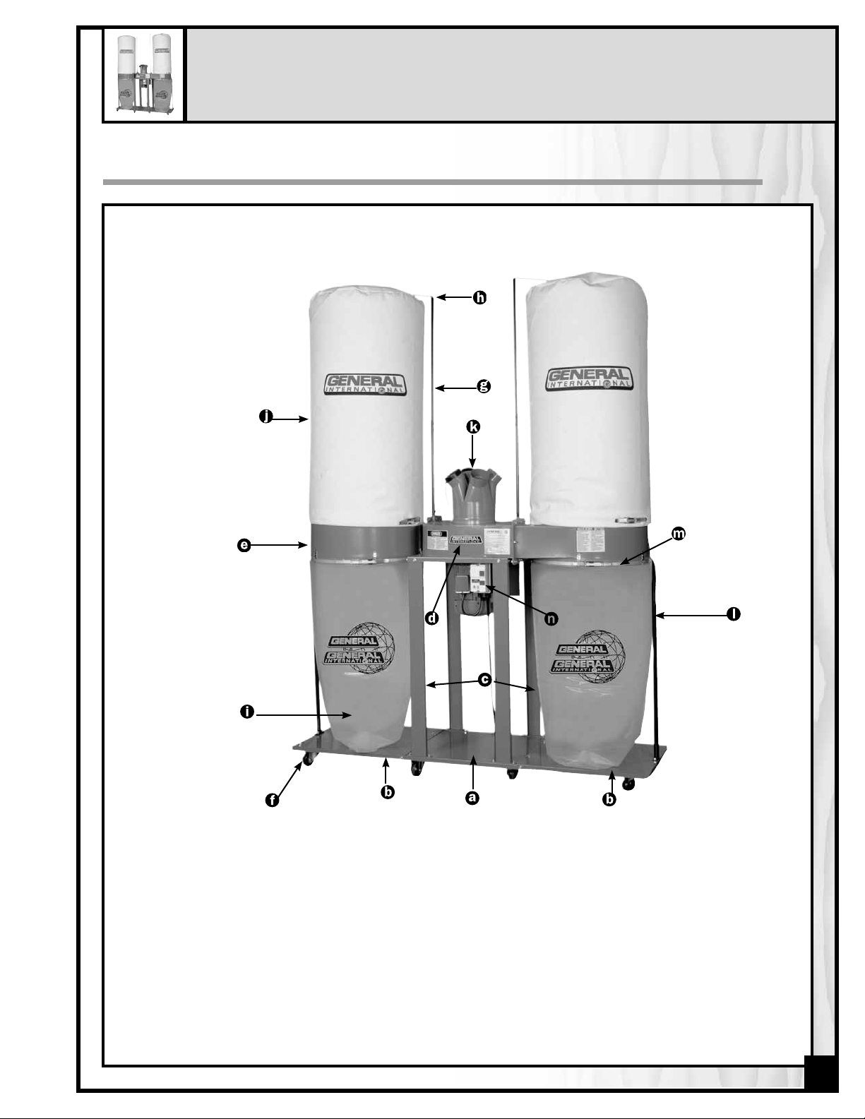
IDENTIFICATION OF MAIN PARTS AND COMPONENTS
10-510
A. MIDDLE BASE PLATE
B. SIDE BASE PLATE
C. LEG
D. COLLECTOR BODY W/FAN & MOTOR ASSEMBLY
E. DRUM
F. CASTER
G. UPPER BAG SUPPORT ROD
H. BAG HANGER
I. COLLECTOR BAG
J. FILTER BAG
K. HOSE INLET (4-HOLE MANIFOLD)
L. VERTICAL SUPPORT ROD
M. BELT CLAMP
N. SWITCH ASSEMBLY
5
Page 6
5 HP DUST COLLECTOR
10-510CF
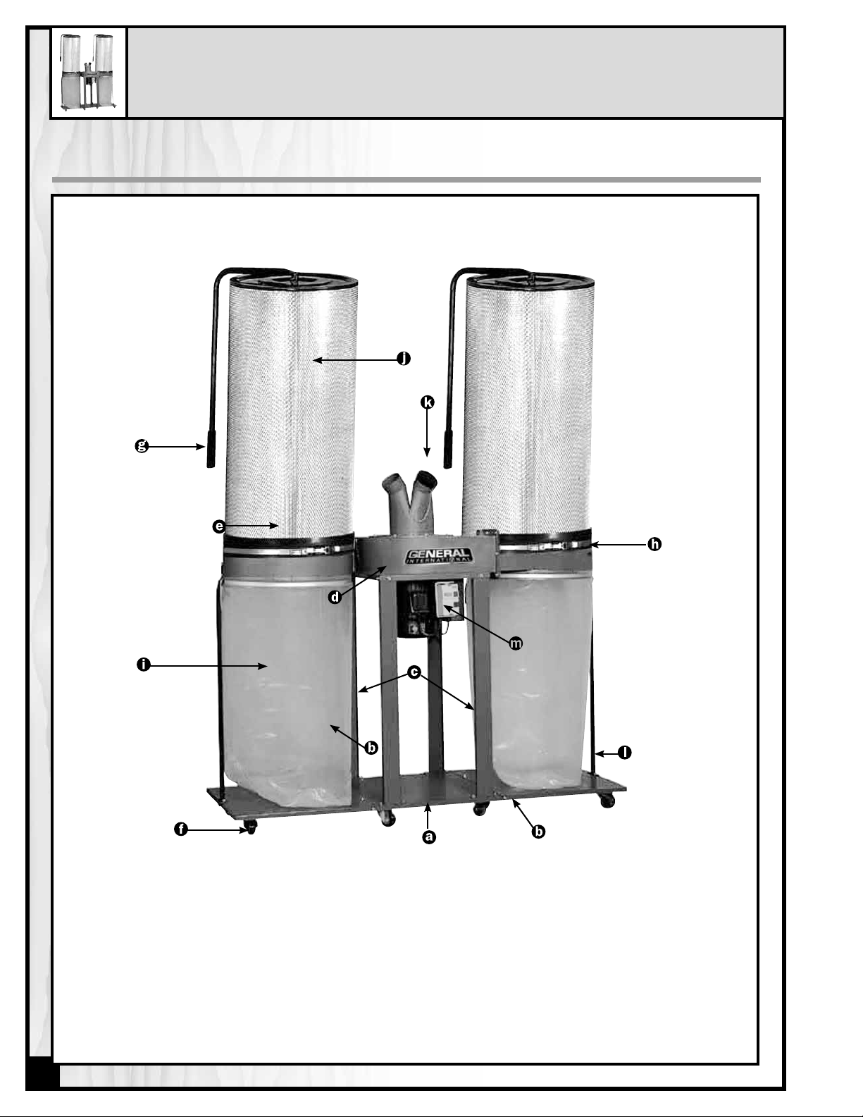
IDENTIFICATION OF MAIN PARTS AND COMPONENTS
10-510CF
A. MIDDLE BASE PLATE
B. SIDE BASE PLATE
C. LEG
D. COLLECTOR BODY W/FAN & MOTOR
ASSEMBLY
E. DRUM
F. CASTER
G. FILTER CLEANING HANDLE
H. BELT CLAMP
I. COLLECTOR BAG
J. CANISTER FILTER
K. HOSE INLET (4-HOLE MANIFOLD)
L. VERTICAL SUPPORT ROD
M. SWITCH ASSEMBLY
6
Page 7

UNPACKING AND PREPARATION FOR SET-UP & ASSEMBLY
SAFETY
Use caution and wear gloves when handling
metal parts such as the belt clamps, which can
cut if handled carelessly.
The model 10-510 is a heavy machine (370 Lbs.
shipping weight - 168 kg.) Do not overexert.
Arrange to have help nearby and ready for
unpacking and set up.
The sound level of this machine is rated at
approximately 85-95 db during operation. Make
sure that adequate hearing protection is used
and that the overall sound level within the working environment is taken into consideration.
ADDITIONAL REQUIREMENTS FOR SET-UP & ASSEMBLY
• Flat piece of wood (such as a ruler)
• Medium Phillips Screwdriver
• 2 extra people for help with lifting
• 10 & 12 mm open end wrench or adjustable
wrench
UNPACKING
Carefully unpack and remove the unit and its components from its shipping containers and check for missing or
damaged items as per the list of contents below.
Note: Please report any damaged or missing items to your General® International distributor immediately.
LIST OF CONTENTS
10-510 10-510 CF
A. MIDDLE BASE PLATE
B. SIDE BASE PLATE 2 2
C. LEG 4 4
D. COLLECTOR BODY W/FAN & MOTOR ASS’Y 1 1
E. DRUM 2 2
F. CASTER 8 8
G. RUBBER GASKET 2 2
H. UPPER BAG SUPPORT ROD 2 N/A
I. BAG HANGER 2 N/A
J. HARDWARE & ACCESSORIES BAG 1 1
- INSTRUCTION MANUAL 1 1
- FOAM GASKET 2 2
- FLANGE BOLTS 5/16” X 1/2” 64 64 64
- HEX BOLTS 5/16” X 1” 16 16
- FLANGE BOLTS 1/4” X 1/2” 6 6
- WASHERS 32 32
- NUTS 5/16” 16 16
- PAN HEAD SCREW 3/16 X 3/8 1 1
- 10-12 mm WRENCH 1 1
K. COLLECTOR BAG 5 5
L. FILTER BAG 2 N/A
M. HOSE INLET (4-hole manifold) 1 1
N. VERTICAL SUPPORT ROD 2 2
O. CANISTER FILTER N/A 2
P. BELT CLAMP 4 4
1 1
(N/A=NOT APPLICABLE FOR THIS MODEL)
7
Page 8

SHOP PLACEMENT / SPACE CONSIDERATIONS
Because each shop situation is unique, the following factors should be taken into consideration when determining
and before deciding on the ideal installation to best suit your shop dust collection needs.
The unit should be installed as close to the dust source(s) as possible.
The base of the unit is mounted on casters and as such the dust collector can be moved from one location to
another within the shop if a permanent installation location is not practical or desired.
In all cases the unit should be installed on a flat, sturdy and stable surface that is able to support the weight of the
unit (370 LBS - 168 kg) as well as the weight of the operator. The casters should be blocked to prevent the unit from
moving when it is in use.
MODEL #10-510
Fig.1
MODEL #10-510CF
Fig. 2
The dust collector is equipped
with a 9” main hose inlet that is
fitted with a multi-inlet manifold
allowing you to connect up to
four 4” dust hoses. (See Fig. 3)
104”
77”
26”
94”
77”
26”
4”
9”
Fig. 3
Consider the space requirements for the unit and its use when deciding where to install
your dust collector in your shop. (See Fig. 1, 2)
LAYING OUT A PLAN FOR THE PIPING:
For permanent installations it is advisable to map out a rough layout of your planned installation starting from the
dust collector out to all the machines that you wish to connect to the system. You may vary your layout to suit your
specific shop needs and may choose to use metal or plastic ducting, or flexible hose in any combination as suited
to your needs.
Fig. 4 Fig. 5
Note: To avoid accidents as well
as damage to ducting or hoses,
plan your installation with hoses
and ducting running along walls or
mounted from above wherever possible. See the accompanying examples (Fig. 4, 5) of non-recommended
and recommended installations.
Hoses and ducting running along the shop floor between machinery can cause users to trip and lead
to serious injury.
8
ON
O
FF
NOTE
Don’t keep hoses and ducting along the
floor.
ON
O
FF
NOT
E
Keep hoses and ducting safely mounted,
either along the walls or ceiling
Page 9

ASSEMBLY INSTRUCTIONS
INSTALLING THE CASTERS:
Turn the 3 base plates (middle, right and left) up-
1.
side down.
JOINING THE BASE PLATES TOGETHER:
Connect the middle base plate to the side base
1.
plates using (4) 5/16” x 1/2” (8 x 8 x 12 mm)
flange bolts for each end of the middle base
plate.
2. Attach the casters using (4) 5/16” x 1/2” flange bolts
per caster.
2. Screw 2 bolts in the top and one in the front and
back vertical edge as shown.
ATTACHING THE LEGS TO FAN/MOTOR ASSEMBLY:
Note: Help with lifting will be needed at this time. The collector body is heavy - do not overexert.
With the help of an assistant turn the collector body
1.
assembly upside down.
2. Align and attach the (4) legs to the frame of the col-
lector body using 8 x 5/16” x 1/2” hex bolts (2 per
leg). Be sure to tighten the bolts securely.
9
Page 10

INSTALLING THE FAN/MOTOR ASSEMBLY ONTO THE BASE:
Tip/Hint: Have 2 people turn the collector body right
side up (See Fig. 12) and support the weight while the
third person aligns and attaches the legs to the base.
A
Connect the legs from collector body with fan
1.
& motor assembly to the base using 8 x 5/16” x
1/2” hex bolts (2 per leg, A). Be sure to tighten the
bolts securely.
FITTING THE RUBBER GASKETS TO THE DRUMS:
mount the gaskets to the outlets on the 2 drums, slip
To
(3) 5/16” x 1” hex bolts through the top holes of the
drum outlet to help hold and align the gasket.
Note: Fit the gasket to the outlet with the flat surface
facing out and the ridged surface against the outlet on
the drum.
ATTACH THE DRUMS TO THE COLLECTOR BODY:
A
B
washer
nut
C
washer
collector
body
Note: Help with lifting will be needed at this time.
gasket
drum
outlet
Using 2 wrenches attach the drums to the collector
body and fan assembly using (16) 5/16” x 1” hex bolts,
32 washers and 16 nuts, A & B. Be sure to tighten the
bolts securely and make sure the gasket stays aligned.
(See C for order of assembly)
bolt
INSTALL THE VERTICAL SUPPORT RODS:
Attach the vertical support rods to each end of the
base and to each drum using (8) 5/16” x 1/2” hex
bolts as shown.
10
Page 11

ASSEMBLE AND ATTACH THE UPPER BAG SUPPORT ROD: (MODEL 10-510 ONLY)
bag hanger
upper bag
support rod
Connect the upper bag support rod to the bag
hanger with the 1/4” x 1/2” hex head bolts (2 per rod).
FIT THE COLLECTION BAGS TO THE DRUMS
Use caution and wear gloves when handling
metal parts such as the belt clamps, which can
cut if handled carelessly.
Fit the clear plastic collector bags over the bottom
1.
openings on the drums and use the hooks on the
drums to temporarily hold the bags in place.
Mount the assembled bag hanger onto the metal rod
located at the top of the collector body and attach it
by using 1/4” x 1/2” hex head bolts.
2. Use the belt clamps to hold the bags securely on
the drum. Before tightening down the belt clamp
make sure the metal strap is sitting in the groove on
the lower portion of the drum.
FIT THE FILTER BAGS TO THE DRUMS: (MODEL 10-510 ONLY)
Slip a belt clamp through the opening in the bot-
1.
tom of each filter bag until it comes out through the
hole at the other end.
hook
A
B
2. Hook the top loop of the filter bags over the hook
on the bag hangers, A.
3. Fit the filter bags over the top edge of the drums
and use the belt clamps to secure the bags on the
drum, B. Before tightening down the belt clamp
make sure the metal strap is sitting in the groove
on the upper portion of the drum.
11
Page 12

FIT THE CANISTER FILTERS TO THE DRUMS : (MODEL 10-510CF ONLY)
A
INSTALL THE HOSE INLET:
Fit the canister filters onto the top opening on the
1.
drums, A.
Tip/Hint: To seat the canister on the rim of the drum, run a flat
piece of wood (such as a ruler) between the drum and the black
apron on the bottom of the canister.
Use the belt clamp to hold the canister filter secure-
2.
ly onto the drum.
INSTALL FOAM GASKETS (IF NEEDED)
Basic assembly is now complete and your dust collector is
ready to be put into service. Once the unit is hooked up to
an appropriate electrical connection, check for air leaks
around the bags or canisters (model 10-510CF). If necessary to seal an air leak, peel off the backing and stick the
adhesive foam gasket onto the drum, making sure the
gasket is sitting in the appropriate groove on the drum.
Fit the hose inlet (4-hole manifold) over the main air
inlet, and secure it in place using the 3/16” X 3/8” metal
screw.
OPERATING INSTRUCTIONS
Always turn on the dust collector before starting your dust producing machine and always stop the dust producing machine before turning off the dust collector.
BEFORE STARTING
1. To minimize airborne dust make sure that all hoses,
fittings and clamps are secure and airtight.
2. For maximum system efficiency, make sure a cover
is installed on any unused hose inlet openings.
3. Never operate the machine without two filters (bag
or cartridge) and two collection bags properly
installed.
The sound level of this machine is rated at approximately 85-95 dB during operation. Make sure that adequate
hearing protection is used and that the overall sound level within the working environment is taken into consideration.
12
Page 13

BASIC INSTRUCTIONS
MAG
DÉMARREUR MAGNÉTIQUE
The MODEL 10-510 & 10-510CF Dust Collector has been designed to capture remove and collect non-metallic
dust and wood dust around the workshop and from woodworking machinery. This machine is designed for a continuous duty rating for industrial applications.
ON/OFF SWITCH
The unit is supplied with a MAGNETIC SAFETY SWITCH
designed to protect the unit and the user from power
surges, power outages and unwanted or unintentional
start-up.
START
The switch assembly is equipped with a GREEN “Start”
BUTTON and a RED spring loaded “STOP” button.
Once the RED “STOP” BUTTON has been pressed, the
machine can only be started by turning the BLACK
inner part of the button to the right to release the stop
button.
MAGNETIC SWITCH
TO START THE MACHINE:
Release the RED STOP BUTTON and then press the
GREEN START BUTTON.
Turning the black part to right will release stop button
NETIC SWITCH
BUTTON
STOP
BUTTON
TO STOP THE MACHINE:
Push on the RED STOP BUTTON and wait for the motor
to come to a complete stop.
When you have finished using the machine be sure to
unplug the machine from the power source or turn off
the power at the wall panel or circuit breaker.
MAINTENANCE, SERVICING AND LUBRICATION
This machine operates on 220 V single phase power (M1 model only); if you suspect any electrical problems call
a qualified electrician to do the verification of the electrical circuit or the machine. If you need further help with your
dust collector contact your General® International distributor or call our Technical Support at (514) 326-1161.
Make sure the switch is in the «OFF» position and unplug the unit from the power source and flip the
breaker to «OFF» position at the wall panel before performing any maintenance.
13
Page 14

• All bearings are sealed and permanently lubricated. No further lubrication is needed.
• Periodically inspect all hardware, fittings and fasteners that may have loosened due to vibration - re-tighten as
needed.
• To minimize airborne dust particles periodically inspect all dust collection fittings - re-tighten as needed.
• Keep the outside of the unit clean and wipe off excessive dust or dirt with a dry rag.
• Clean filters (bags on 10-510 or canisters on 10-510CF) on a regular basis and replace as needed.
• Periodically inspect inside of all pipes, fittings, hoses, blast gates, and connectors for accumulated dust build up or other obstructions and clean as needed. Remove sections and vacuum or manually remove debris as
needed.
• Check and if necessary replace all damaged parts or components.
• Do not operate with a damaged filter bag or cartridge - replace a damaged filter immediately.
• Periodically inspect the power cord and plug for damage. If necessary replace the power cord and the POWER
RECEPTACLE at the first signs of visible damage.
• Use only recommended parts and accessories. The use of parts or accessories NOT recommended by
GENERAL® INTERNATIONAL may result in a risk of injury or damage to the machine.
CLEANING OR REPLACING THE FILTER BAGS (10-510 only):
Turn the switch to the “OFF” position and unplug the unit from the power source before cleaning or
replacing filter bags or before performing any maintenance
Tip/Hint: To avoid potentially costly down-time, consider keeping a spare filter bag on-hand and nearby for use if
needed.
After a period of time depending on the frequency of use, the filter bags may become clogged and affect airflow
as well the overall efficiency of the unit. Should you notice a drop in the efficiency or performance of the unit, it
may be a sign that it is time to clean the filters bags. If so, proceed as follows:
1. Turn off and unplug the machine.
2. Unclip the belt clamp and remove the bag from the machine.
3. Clean the dust from inside the filter bag using a vacuum.
4. For extreme cases, after the initial cleaning with a vacuum, turn filter bag inside out and vacuum a second time,
laying the bag on flat hard surface (such as a table or workbench) and slowly passing the vacuum nozzle over
the entire surface area.
5. Re-install the bag and re-attach the clamp.
Note: Filter bags can also be machined washed (gentle cycle only) in cold or warm water. (Do not use hot water)
Do not use detergent. Make sure the bag has completely dried before re-installing on the machine.
14
For machine washing, make sure to remove the belt clamp from the bag before washing!
Page 15

CLEANING OR REPLACING THE CANISTER FILTERS
(MODEL 10-510CF)
Turn the switch to the “OFF” position and unplug the unit from the power source before cleaning or
replacing canister filters or before performing any maintenance.
After a period of time depending on the frequency of use, the canister filter may become clogged and affect airflow as well the overall efficiency of the unit. Should you notice a drop in the efficiency or performance of the unit,
it may be a sign that it is time to clean the filters.
If so, proceed as follows:
1. Turn off and unplug the machine.
2. For basic cleaning, simply rotate the handle of the
canisters several rotations, A. The internal flap will rub
against the corrugated inner filter and shake free any
built-up dust from inside the filter.
3. For a more thorough cleaning, after rotating the han dle, unclip the belt clamps and remove the canisters
from the machine and place them on the ground
upside down.
4. Vacuum the inside of the canisters to remove any
remaining dust from inside.
5. Re-install the canisters and re-attach the clamps, B.
A
B
EMPTYING THE COLLECTOR BAGS:
Turn the switch to the “OFF” position and unplug the unit from the power source before emptying or
replacing the collector bags or before performing any maintenance.
Note: Depending on your needs, shop situation and local regulations collections bags can be emptied and re-used
or disposed (with their contents) and replaced with a new bag.
1. Turn off and unplug the machine.
2. Unclip the bag clamp, A, and remove the bag from
the machine.
3. Empty the bag (or simply dispose of the bag and it’s
contents and replace with a new bag) disposing of
the contents in a safe and responsible manner that
complies with all local codes and regulations
regarding waste disposal.
4. Re-install the bag and re-attach the clamp, A.
A
B
15
Page 16

RECOMMENDED OPTIONAL ACCESSORIES FOR YOUR DUST COLLECTOR
We offer a large variety of products to help you increase productivity, accuracy and safety when using your dust
collector. Here’s a small sampling of accessories available from your local General International dealer.
4” to 2 1/2 ”
REDUCER
# 10-086
4” X 10’ HOSE
# 10-410
CANISTER FILTER
# 10-516C
INLET COVER
(4” CAP)
# 10-088
DUST COLLECTOR
ACCESSORY KIT
#10-100
(1 Machine Hook-up)
#10-200
(2 Machine Hook-up)
16
2 MICRON DUST
FILTER BAG
# 10-515
WINDOW TYPE
COLLECTOR BAG
# 10-525
CLEAR PLASTIC
COLLECTOR BAG
# 10-520
Page 17

29N
34N
35
42
16
12
8
10
9
37
37
33N
11
28
25
27
24
26
34N
29N
28
38
24
27
30
32
2
31
2
5
6
1
2
1
2
1
2
1
2
31
2
30
32
2
13
14
24
25
18
17
41
36
2
23
22
21
15
25
2
37
37
33N
40
39
2
2
7
4
3
4
43
Model #10-510
17
Page 18

PARTS LIST
10-510/510CF
PART N0. DESCRIPTION SPECIFICATION QTY
10510-01 CASTER 3” 8
10510-02 FLANGE BOLT 5/16” X 1/2” 64
10510-03 MIDDLE BASE PLATE 1
10510-04 SIDE BASE PLATE 2
10510-05 RIGHT LEG 2
10510-06 LEFT LEG 2
10510-07 HOUSING 1
10510-08 CAP SCREW M6 X 20MM 1
10510-09 HEX. HD. BOLT 3/8” X 1” 1
10510-10 WASHER 1
10510-11 IMPELLER 1
10510-12 INLET COVER 1
10510-13 MOTOR GASKET 1
10510-14 MOTOR 1
10510-15 KEY 8X8X50 1
10510-16 FLANGE BOLT 5/16” X 3/4” 8
10510-17 SWITCH 1
10510-18 PHILLIPS HD. SCREW 3/16” X 3/4” 2
10510-21 STRAIN RELIEF 3
10510-22 POWER CORD 1
10510-23 MOTOR CORD 1
10510-24* WASHER 5/16” X 23MM 40
10510-25 HEX. HD. BOLT 5/16” X 1” 4
10510-26 NUT 5/16” 20
10510-27 GASKET 2
10510-28 DRUM 2
10510-29 FILTER** 2
10510-30 BOTTOM COLLECTOR BAG (ITEM #10-520) 2
10510-31 VERTICAL SUPPORT ROD 2
10510-32 BELT CLAMP 4
10510-33* UPPER BAG SUPPORT ROD 2
10510-34* BAG HANGER 2
10510-35 INLET (4-HOLE MANIFOLD) 1
10510-36 PHILLIPS HD. SCREW 3/16” X 3/4” 2
10510-37* FLANGE BOLT 1/4” X 1/2” 6
10510-38 HEX HD. BOLT 5/16” X 1” 16
10510-39 ALLEN KEY 5MM 1
10510-40 OPEN END WRENCH 10 X 12 MM 1
10510-41 SWITCH PLATE 1
10510-42 PAN HD. SCREW 3/16” X 3/8” 1
10510-43 FOAM GASKET 2
*Not supplied/required for Model 10-510CF
18
**Filter bag #10-515 for model 10-510 or Canister filter #10-516C for model 10-510CF.
Page 19

Canister supplied on Model #10-510CF
PARTS LIST
10-516C
PART # DESCRIPTION SPEC. QTY
10516C-25 CANISTER FILTER DIA. 600MM 1
10516C-26 NUT 5/16” 1
10516C-27 SET SCREW 5X12”X3/4” 1
10516C-28 HANDLE 1
10516C-29 SPONGE HANDLE 7/8” 1
10516C-30 END CAP 3/4” 1
10516C-31 BELT CLAMP 1
10516C-32 CANISTER FIXING PLATE 7/8” 2
10516C-33 BEARING 1206 2
10516C-35 FLANGE BOLT M5X12 16
PART # DESCRIPTION SPEC. QTY
10516C-36 BOTTOM FIXING PLATE 1
10516C-37 FIXING PLATE 2
10516C-38 PHILLIPS HEAD SCREW M5X15 4
10516C-39 FOAM GASKET 5X45X200 1
10516C-40 ROUND HEAD SCREW M5X6 6
10516C-41 SPINDLE 1
10516C-42 FOAM GASKET 5X42X2000 1
10516C-44 FLAPPER ARM 6
10516C-46 NUT M5 12
10516C-47 FLAPPER BRACKET 2
19
Page 20

10-510CF M1
Models 10-510 M1 & 10-510CF M1
10-510 M1
8360 Champ-d’Eau, Montreal (Quebec) Canada H1P 1Y3
Tel.: (514) 326-1161
Fax: (514) 326-5565 - Parts & Service / Fax: (514) 326-5555 - Order Desk
orderdesk@general.ca
www.general.ca
IMPORTANT
When ordering replacement parts, always give the model number, serial number of the machine and
part number. Also a brief description of each item and quantity desired.
 Loading...