

Page 1
Sound hood for quiet operation.
Wet/dry operation.
Sealed, water resistant switch cover.
2 Stage air filtration.
Powerful 2 speed motor. (MODEL 10-300)
2 High efficiency motors. (MODEL 10-315)
Rated for heavy duty maintenance &
janitorial use.
Accessory tray included.
CAPACITY
10 GALLON
- #10-300
15 GALLON
- #10-315
V
OLTAGE
110 V
AIR MO
VEMENT
92 CFM
- #10-300
93 CFM & 122.4 CFM
- #10-315
SUCTION (WATER LIFT)
72” (MAX.)
- #10-300
73” (MAX.)
- #10-315
HOSE LENGTH
6’ (2 m)
SOUND RA
TING
75 TO 80 dB
- #10-300
75 TO 80 dB (2 MOTORS: 95 TO 100 dB)
- #10-315
MOTOR
1 1⁄2 HP (HI: 10 A / LOW: 7 A)
- #10-300
1 1⁄2 HP (1 MOTOR: 10 A / 2 MOTORS: 19 A)
- #10-315
WEIGHT
39.6 LBS (18 kg)
- #10-300
56 LBS (25.5 kg)
- #10-315
REVISION 3 - MAY 08/07
© COPYRIGHT GENERAL INTERNATIONAL 05/2007
Page 2

THANK YOU
for choosing this General International model 10-300 or model
10-315 Wet/Dry Vacuum cleaner. This vacuum cleaner has been carefully tested and inspected
before shipment and if properly used and maintained, will provide you with years of
reliable service. To ensure optimum performance and trouble-free operation, and to get the
most from your investment, please take the time to read this manual before assembling,
installing and operating the unit.
The manual’s purpose is to familiarize you with the safe operation, basic function, and features
of this vacuum cleaner as well as the set-up, maintenance and identification of its parts and
components. This manual is not intended as a substitute for formal woodworking instruction,
nor to offer the user instruction in the craft of woodworking. If you are not sure about the
safety of performing a certain operation or procedure, do not proceed until you can confirm,
from knowledgeable and qualified sources, that it is safe to do so.
Once you’ve read through these instructions, keep this manual handy for future reference.
All component parts of General® International machinery are carefully tested and inspected during all stages of
production, and each machine is thoroughly inspected upon completion of assembly. Because of our commitment to quality and customer satisfaction, General® International agrees to repair or replace, within a period of 24
months from date of purchase, any genuine part or parts which, upon examination,prove to be defective in workmanship or material. In order to obtain this warranty, all defective parts must be returned freight pre-paid to
General® International Mfg. Co., Ltd. Repairs attempted without our written authorization will void this warranty.
GENERAL® INTERNATIONAL WARRANTY
Disclaimer:
The information and specifications in this manual pertain to
the unit as it was supplied from the factory at the time of printing.
Because we are committed to making constant improvements, General
International reserves the right to make changes to components, parts
or features of this unit as deemed necessary, without prior notice and
without obligation to install any such changes on previously delivered
units. Reasonable care is taken at the factory to ensure that the specifications and information in this manual corresponds with that of the unit
with which it was supplied. However, special orders and “after factory”
modifications may render some or all information in this manual
inapplicable to your machine. Further, as several generations of this
model of vaccum cleaner and several versions of this manual may be
in circulation, if you own an earlier or later version of this unit, this
manual may not depict your machine exactly. If you have any doubts
or questions contact your retailer or our support line with the model and
serial number of your unit for clarification.
GENERAL® INTERNATIONAL
8360 Champ-d’Eau, Montreal (Quebec) Canada H1P 1Y3
Telephone (514) 326-1161 • Fax (514) 326-5555
www.general.ca
Page 3

Rules for Safe Operation
1. Learn the machine’s specific applications and limitations (what it can
and cannot do), as well as the specific potential hazards that are particular to this machine. Carefully
follow all operation instructions and
safety rules.
2. Do not operate the unit unless the
hose is installed on the dust outlet.
3. Keep the work area clean and well
lit.
4. Do not wear loose tilting clothing or
jewelry. Wear face, eye, ear, respiratory and body protection suitable to
the application or operation being
performed.
5. Do not vacuum near flammable or
combustible liquids, gases or vapors.
Avoid materials such as: gasoline or
other fuels, ligter fluid, cleaning fluid,
natural gas, hydrogen, or explosive
dust, magnesium dust, grain dust
or gun powder.
6. Never leave the power on or the machine running while it is unattended.
7. Do not handle the power cord or the
electrical plug with wet hands.
8. Do not vacuum anything that is burning or smoking such as cigarettes,
matches or hot ashes.
9. To avoid health hazards from vapors or
dusts, do not vacuum toxic materials.
10. The unit is equipped with a three prong
electric plug and should be plugged
into a three pole receptacle. Never remove the third prong.
11. Always disconnect the unit from the
power supply before servicing, emptying or when changing tools or filters.
12. Make sure that the switch is in the “OFF”
position before plugging in the power
cord.
13. Do not use this wet/dry vacuum for
purposes other than its intended use. If
used for other purposes, General International disclaims itself of any and
all warranty, real or implied, and holds
itself harmless for any injury which
may result from such use.
To help ensure safe operation, please take a moment to learn the machine’s applications and limitations, as well as potential hazards. General® International disclaims any real or implied warranty and
holds itself harmless for any injury that may result from improper use of its equipment.
Page 4
WET / DRY VACUUM CLEANER
10-300 / 10-315
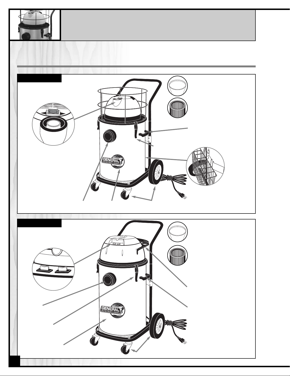
IDENTIFICATION OF PARTS & COMPONENTS
POWER CORD/PLUG
110 Volt A.C. To prevent damage
to the power cord, to not unplug
by pulling on the power cord always handle by the plug.
FRONT CASTERS
& REAR FIXED WHEELS
10 GAL. TANK
MODEL 10-300
POWER SWITCH
Sealed, water resistant three position
switch: Low – Off – High.
FILTER BAG
Designed to keep dust in the
canister and away from the
motor.
POWER CORD/PLUG
110 Volt A.C. To prevent damage
to the power cord, to not unplug
by pulling on the power cord always handle by the plug.
FRONT CASTERS
& REAR FIXED WHEELS
LIFTING HANDLES
On each side of the tank.
15 GAL. TANK
HOSE INLET
MODEL 10-315
POWER SWITCH
Sealed, water resistant switch: On /Off.
FILTER BAG
Designed to keep dust in the
canister and away from the
motor.
PLEATED INNER FILTER CARTRIDGE
Should be removed for wet vacuuming. Provides secondary dust
filtration up to 3 microns.
4
ACCESSORY STORAGE RACK
AIRFLOW INDICATOR
When the unit is turned on the
airflow indicator will pop up
indicating that air is flowing
through unrestricted and the
unit is functioning properly. If
the airflow indicator does not
pop up, there may be an
obstruction or the tank may be
full: in this case, stop the unit
and check or empty the unit
as necessary.
HOSE INLET
ACCESSORY
STORAGE
RACK
LIFTING HANDLES
On each side of the tank.
PLEATED INNER FILTER CARTRIDGE
Should be removed for wet vacuuming. Provides secondary dust
filtration up to 3 microns.
LID CLAMPS
Secure the lid to
the tank creating
an airtight seal.
LID CLAMPS
Secure the lid to
the tank creating
an airtight seal.
Page 5
ELECTRICAL REQUIREMENTS
Plug the vacuum into a proper receptacle.Your power tools should be
connected to a dedicated electrical circuit of not less than #14 wire and
should be protected with a 15 amp time lag fuse.
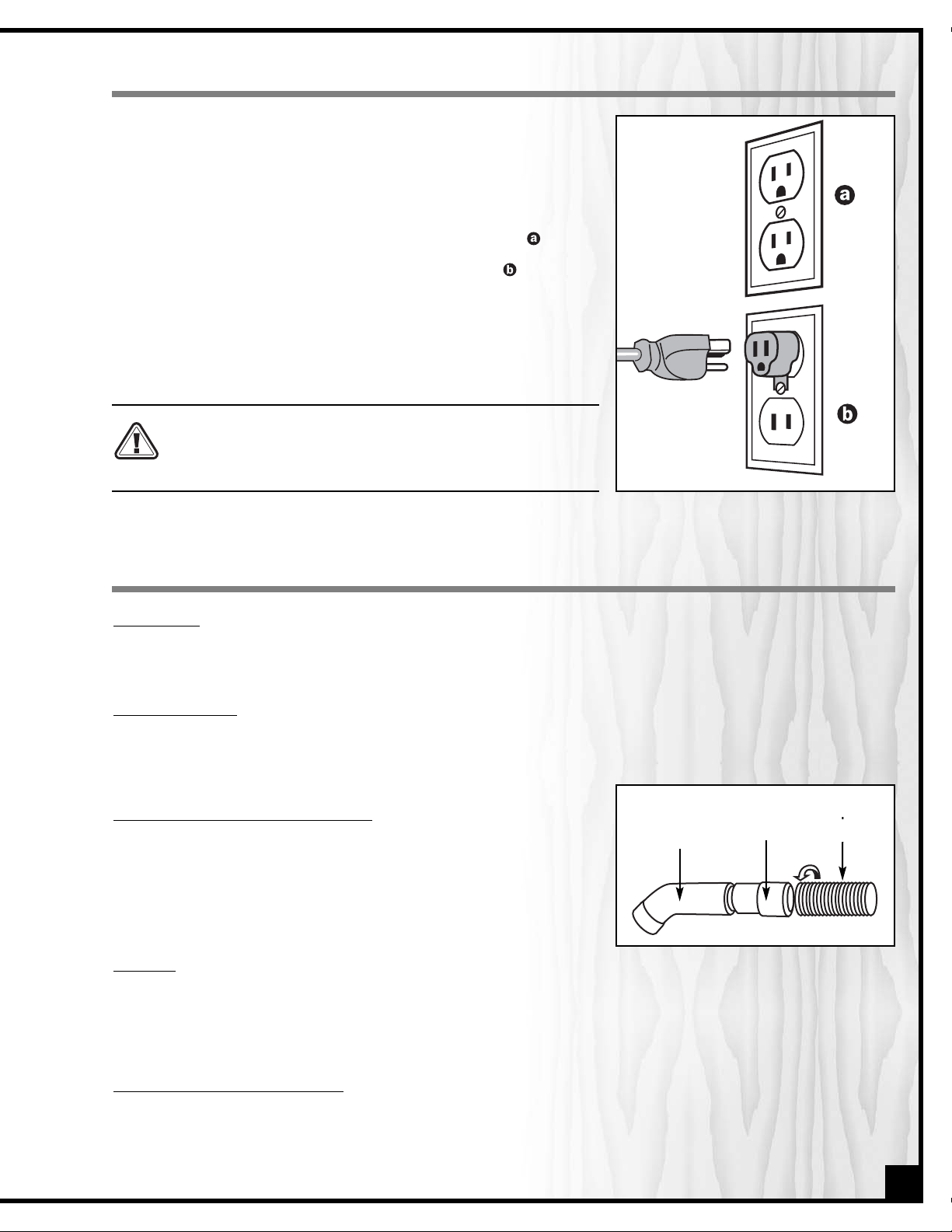
Grounding:
This tool must be grounded to protect the operator from
electrical shock. The supplied motor recommended for your vacuum is
wired for 110 Volt, single phase, and has a 3-conductor cord and 3prong grounded plug to fit a grounded-type receptacle, . Do not
remove the 3rd prong (grounding pin) from the plug to make it fit into
an old 2-hole wall socket. If an adapter plug is used, , it must be
attached to the metal screw of the receptacle.
Note: Use of an adaptor plug is illegal in some areas. Check your local
codes.
BEFORE CONNECTING THE MOTOR TO THE POWER LINE, MAKE SURE
THAT THE SWITCH IS IN THE OFF POSITION AND THAT THE ELECTRICAL
CURRENT IS OF THE SAME TYPE AS THAT STAMPED ON THE MOTOR
NAME PLATE. ALL ELECTRICAL CONNECTIONS SHOULD HAVE PROPER
CONTACT. RUNNING ON LOW VOLTAGE WILL DAMAGE THE MOTOR.
OPERATION INSTRUCTIONS
FLEXIBLE HOSE
Be sure that the hose is firmly connected to the inlet nozzle.When properly connected it can only be unclipped from
the air inlet by depressing the button on the hose end while pulling on the hose.
FILTER INSTALLATION
Install the bag filter on the rim of the tank. Proper installation of the bag filter creates a seal that will ensure maximum performance and prolong the life of the unit by protecting the motor against dust infiltration. The bag filter
should be used at all times, for both wet or dry vacuuming.
EXTENSION WAND AND NOZZLE CONNECTION
The 2 piece extension wand twist-fits into the female end of the curved
end pipe installed at one end of the flexible hose. The nozzles are
designed to twist fit into the female end of the extension wand. To
disassemble, pull while twisting to separate the components. To avoid
damaging the hose, pull on the hose fittings and not directly on the
hose.
FLOAT CUP
To prevent overfilling the tank with water which could damage the motor and/or cause electrical shock to the user,
the vacuum is equipped with a float cup. When the tank fills to its limit with water the sound of the motor will change
as the float cup rises and seals off the motor to prevent the rising water from entering. At this point the unit will not
vacuum up any more water or debris and the tank must be emptied before work can continue.
REMOVING AND RE-INSTALLING THE LID
• To remove the lid, release the three lid clasps and lift the lid from the canister.
• To re-attach the lid, fit the lid securely to the canister and using the three clasps, clip the lid in place.
Note: For maximum performance a proper seal is required between the lid and the canister.
5
CURVE PIPE
HOSE
HOSE END
Page 6

FILTRATION SYSTEM
This wet dry vacuum is designed with 2 stage air filtration comprised of a filter bag and a pleated inner filter
cartridge. To ensure maximum performance and to protect the motor against dust infiltration make sure that the filtration is properly installed and used at all times.
1. When vacuuming dry trash or dust, both the filter bag and the pleated inner filter cartridge should be installed.
2. When vacuuming wet trash or liquids, remove the pleated inner filter cartridge as only the filter bag is needed.
TURN OFF THE UNIT AND UNPLUG THE POWER CORD BEFORE REMOVING OR INSTALLING THE FILTERS.
WARNINGS FOR OPERATING
1. Do not use to vacuum up gasoline, or other flammable liquids or vapors. Also avoid using
for nails, blades, screws or other sharp objects that could damage the hose or perforate
the filter bag.
2. The airflow indicator will pop up when air is flowing unrestricted and the unit is functioning properly. If the air flow indicator does not pop up, there may be an obstruction or
the tank may be full: in this case, stop the unit and check or empty the unit as necessary.
(Model 10-300 only)
3. To avoid the build up a strong smells inside the tank, clean and empty the unit after each
use or before storing for prolonged periods.
4. Do not use the unit near sources of heat such as ovens, radiators or space heaters. Exposure
to heat may cause the tank to buckle, bulge or lose its shape preventing a good seal
between the tank and lid which will diminish performance and suction efficiency.
5. To avoid the build-up of static electricity in the extension wand, do not suck up too much
fine dust at one time.
6. To prevent damage to the motor, before operating, make sure that the filter bag is in place,
properly fitted and is not perforated. Periodically inspect the filter bag for holes or perforations. The filter bag should be replaced immediately if damaged or perforated.
ITEM #10-323
PROFESSIONAL
WET NOZZLE
Used for water removal.
ITEM #10300-35B
WET NOZZLE
Used for water removal.
ITEM #10-314
12” BRUSH NOZZLE
Used on floors or carpets.
ITEM #10-310
CREVICE
NOZZLE
Used in corners or
tight spaces.
ITEM #10300-11B
ROUND BRUSH
NOZZLE
Used on fabric or any
irregular surface.
ITEM #10-306
FLEXIBLE
6’ HOSE
ITEM #10-309
2 PIECE
EXTENSION WAND
ITEM #10-332
PLEATED FILTER
CARTRIDGE
ITEM #10-334
CLOTH FILTER BAG
REFERENCE GUIDE FOR REPLACEMENT & OPTIONAL ACCESSORIES
OPTIONAL
18’ FLEXIBLE HOSE
ITEM #10-318
6
Page 7

MAINTENANCE
1. Keep all parts and accessories such as the hose, power cord and filters in good condition
2. Clean the filter bag by hand, never by washing machine.
3. For smooth rolling, apply a small amount of lubricant to the castors.
4. Wipe the unit clean using a sponge, cloth or paper towel with warm water and mild detergent.
PROBLEMS
MOTOR STOPS OR
DOES NOT RUN
AIRFLOW INDICATOR
DOES NOT POP UP
(MODEL 10-300 ONLY)
CHECK THE FOLLOWING
1. Power cord properly plugged in?
2. Switch in the “off” position?
3. Overheating? If thermal protector shuts down the
unit, let the unit cool down or about 10 minutes
before restarting.
1. Hose and fittings connected tightly? Reconnect
hose and fittings.
2. Hose or fittings clogged? Dust tank full? Unblock
hose or fittings or empty tank.
3. Filter bag clogged with dust? Wash or replace
filter bag.
TROUBLESHOOTING
7
Page 8

8
MODEL 10-300
Page 9

9
PARTS LIST
10-300
PART N0.
10300-01
10300-02
10300-03
10300-04
10300-05
10300-06
10300-07
10300-08
10300-09
10300-10
10300-15
10300-16
10300-17
10300-18
10300-19
10300-20
10300-21
10300-22
10300-23
10300-23-1
10300-24
10300-25
10300-26
10300-27
10300-28
10300-29
10300-30
10300-31
10300-32
10300-33
10300-34
10300-35
10300-36
10300-37
10300-38
10300-39
10300-40
10300-41
10300-42
10300-43
10300-44
10300-45
10300-46
DESCRIPTION
LID HANDLE
WATER PROOF GASKET
WATER PROOF COVER
SWITCH
TOP HOOD
AIRFLOW INDICATOR
MUFFLER
MOTOR COVER GASKET
MOTOR COVER
AIRFLOW INDICATOR WASHER
SCREW
POWER CORD CLAMP
STRAIN RELIEF
POWER CORD
MOTOR MOUNT
MUFFLER
ROLL CAGE
MUFFLER
TWO STAGE MOTOR
MOTOR BRUSH
(NOT SHOWN)
FOAM GASKET
MOTOR BASE WASHER
FLAT SUPPORT
SCREW
FLOAT WASHER
FLOAT
FLOAT CAGE
SCREW
CANISTER FILTER (
ITEM
10-332)
CLOTH FILTER CAGE
CLOTH FILTER BAG (
ITEM
10-334)
WASHER
CAP NUT
SCREW
LID CLAMPS
SCREW
WASHER
CLAMP HOOK
SCREW
AIR DEFLECTOR
LIFTING HANDLE
HOSE INLET
10GL TANK
REF. N0.
V02001-00
E31011-01
E31010
E31004
V02011-01
V02123
V02090
V02134-00
V02148-2
V02110-00
S14015
V02107
V02108
E23063
V02034-00
V02090
V03059
V02091
M21117-2
M02017-1
V02111-00
V02113
V02047-00
S14051
V02012A
V02149
V02150
S14038
V03063
V03060
V03910
W10050
N11050
T54012
V03909
T95010
W10050
V03107
S54012
V02103
V02006-00
V02100-00
V03064
QTY
1
1
1
1
1
1
1
1
1
1
2
1
1
1
1
1
1
1
1
1
1
1
1
4
1
1
1
3
1
1
1
8
8
4
3
8
2
1
7
1
2
1
1
SPECIFICATION
4x12
PA
PVC
14 AWG X 3C X 10 M
ABS
110 V/1000/700 W
EVA FOAM
EVA FOAM
ABS
4 X 5
EVA FOAM
PP
PP
4 X 38
M5
4 X 12
SPCC
M5 X 10
SPCC
4 X 12
ABS
PP
ABS
SUS 304
Page 10

MODEL 10-315
10
Page 11

11
PARTS LIST
10-315
PART N0. REF. NO. DESCRIPTION SPECIFICATION QTY
10315-01 V03001-03 LID HANDLE PA 1
10315-02 V03002-01 LID ABS 1
10315-03 V03003 MUFFLER EVA FOAM 2
10315-04 V03004 LID GASKET PVC 2
10315-05 S14065 SCREW 4x65 8
10315-06 E23064 POWER CORD 12AWGX3CX7.5M 1
10315-07 T54012 SCREW 4x12 4
10315-08 V02108 STRAIN RELIEF PVC 1
10315-09 R01907-03 ACCESSORY RACK PA 1
10315-10 ACCESSORY RACK MOUNT PA 2
10315-14 E30002 SWITCH 2
10315-15 V03005-01A MIDDLE HOOD ABS 1
10315-16 FUSE CASE NUT 2
10315-17 S14065 SCREW 5x40 2
10315-18 S54020 SCREW 4x20 2
10315-19 WIRE AWG 16 2
10315-20 V03007 MUFFLER EVA FOAM 8
10315-21 V02134A MOTOR COVER GASKET EVA FOAM 2
10315-22 V02148 MOTOR COVER PA 2
10315-23 S54012 SCREW 4x12 2
10315-24 S55040 SCREW 4x16 2
10315-25 V02107 CORD CLAMP PA 1
10315-26 S53015 SCREW 3x15 2
10315-27 E11004 WIRE AWG 16 2
10315-28 E60019 WIRE CONNECTOR PA 1
10315-29 V03018-03 MOTOR MOUNT ABS 1
10315-30 V03009 GASKET EVA FOAM 2
10315-31 V03012 MUFFLER FOAM 2
10315-32 V02117 MOTOR BASE WASHER EVA FOAM 2
10315-33 M21210 TWO STAGE MOTOR 1000 W 2
10315-34 V03113 MOTOR BASE SBR 2
10315-35 V03020-03 PROTECTION PA 2
10315-36 V03019 MUFFLER FOAM 2
10315-37 V03013-03 FLAT SUPPORT PP 1
10315-38 VGH06 AIR CONCENTRATOR PP 1
10315-39 S54012 SCREW 4x16 3
10315-40 V02112-2 FLOAT WASHER EVA FOAM 1
10315-41 V03057 FLOAT PP 1
10315-42 V02150 FLOAT CAGE
(#10300-30)
PP 1
10315-43 S54015 SCREW 4x16 3
10315-44 V03063 CANISTER FILTER
(ITEM 10-332)
190x180 1
10315-45 V03060 CLOTH FILTER CAGE
(#10300-33)
1
10315-46 V03910 CLOTH FILTER BAG
(ITEM 10-334)
1
10315-47 W15013 WASHER 8
10315-48 N11050 CAP NUT
(#10300-36)
M5 3
10315-49 T96015 SCREW 4x12 4
10315-50 V03909 LID CLAMP ASS’Y
(#10300-38)
SPCC 3
10315-51 T95010 SCREW
(#10300-39)
M5x10 6
10315-52 T15012-1 WASHER 2
10315-53 V03107 CLAMP HOOK
(#10300-41)
SPCC 1
10315-54 T54015 SCREW 4x12 3
10315-55 V02103 AIR DEFLECTOR
(#10300-43)
ABS 1
10315-56 V03021 TANK HANDLE PP SPCE-1060 USE 2
10315-57 V02100-00 AIR INLET NOZZLE
(#10300-45)
ABS 1
10315-58 V03065 15GL TANK SUS304 SPCE-1060 USE 1
Page 12

12
PARTS LIST
STAND
PART N0.
10300-01A
10300-02A
10300-04A
10300-05A
10300-06A
10300-07A
10300-11A
10300-12A
10300-13A
10300-14A
10300-15A
10300-16A
10300-17A
10300-18A
10300-19A*
10315-19A*
10300-20A
10300-21A*
10300-22A
10300-23A
10300-24A
DESCRIPTION
CART HANDLE
HANDLE CONNECTOR
FIXTURE
CAP NUT
WASHER
SCREW
SHAFT BUSHING
WASHER
FIXED WHEEL
AXLE
WASHER
E-RING
CAP NUT
LOCK WASHER
BASE
(FOR 10-300)
BASE
(FOR 10-315)
CASTER
ACCESSORY STORAGE RACK
(ITEM 10-305)
LOCK WASHER
WASHER
LOCK WASHER
REFE. NO.
V03110
V03104
V03106
N11050
W15010
T15030
V03111
W10001
V03109
V03105
W10001
F10090
N21001
W10011
V03101
V03102
V03108
W20011
W10011
W20011
QTY
1
2
1
4
8
4
2
2
2
1
2
2
2
2
1
1
2
1
2
2
2
SPECIFICATION
M5
M5 X 30
S 45 C
1/2"
8"
S 45 C
1/2"
E9
3/8"UNC
3/8"
2 1/2"
(FOR 10-300 ONLY)
1/8”
1
2
5
6
4
7
20
19
17
22
18
23
24
11
12
13
14
15
16
21
*
*
STAND FOR #10-300 & 10-315
A
Page 13

13
ACCESSORIES FOR #10-300 & 10-315
B
Page 14

14
PARTS LIST
ACCESSORIES
PART N0.
10300-01B
10300-02B
10300-03B
10300-04B
10300-05B
10300-06B
10300-07B
10300-08B
10300-09B
10300-10B
10300-11B
10300-12B
10300-13B
10300-14B
10300-15B
10300-16B
10300-17B
10300-18B
10300-19B
10300-20B
10300-21B
10300-22B
10300-23B
10300-24B
10300-25B
10300-26B
10300-27B
10300-28B
10300-29B
10300-30B
10300-31B
10300-32B
10300-33B
10300-34B
10300-35B
10300-36B
10300-37B
10300-38B
10300-39B
10300-40B
DESCRIPTION
SCREW
BUTTON FIXTURE
BUTTON
BUTTON SPRING
FLEXIBLE HOSE HEAD
FLEXIBLE HOSE
(ITEM 10-306)
FLEXIBLE HOSE END
CURVED PIPE
EXTENSION WAND
(ITEM 10-309)
CREVICE NOZZLE
(ITEM 10-310)
ROUND BRUSH NOZZLE
ROUND BRUSH BASE
ROUND BRUSH RING
12” BRUSH NOZZLE
(ITEM 10-314)
ELBOW
ELBOW RING
NOZZLE
NOZZLE ROLLER SET
(INCLUDE#19/20/21)
ROLLER TIRE
NOZZLE ROLLER
ROLLER AXLE
BRUSH SET
PROFESSIONAL WET NOZZLE
(ITEM 10-323)
ELBOW
ELBOW RING
WET NOZZLE
RUBBER SCRAPER BASE
RUBBER SCRAPER
NOZZLE ROLLER SET
(INCLUDE#30/31/32)
ROLLER TIRE
NOZZLE ROLLER
ROLLER AXLE
SCRAPER HOLDER
SCREW
WET NOZZLE
ELBOW
NOZZLE
SCREW
FIXTURE
RUBBER SCRAPER
REFERENCE NO.
S24006
R02004-00
R02003-00
X00017
R02002-00
R02011-00
R02007-00
R02008-00
A-3-38
VCA-5
A-4-38
R02031-00
R02032-00
A-1-38
R02021-00
R03014-00
R02022-00
R01906
R02030
R02029
U44025
R02023
A-7-38
R02021-00
R03014-00
R02026
R02035
A-6-38
R03006
R02030
R02029
U44025
R02028
S54012
VCB-6-32
VCA-1-2-2
VCB-6-1
S13008
VCB-6-4
VCB-6-5
QTY
1
1
1
1
1
1
1
1
2
1
1
1
1
1
1
1
1
2
2
2
2
2
1
1
1
1
2
2
2
2
2
2
2
2
1
1
1
2
1
1
SPEC.
4 x 6
ABS
ABS
SWPA
ABS
38 x 2000
ABS
ABS
ABS
PP
ABS
PP &PA
ABS
ABS
PP
PVC
ABS
S 45 C
ABS & PA
ABS
ABS
PA
PVC
NBR
PVC
ABS
S 45 C
SPCC
4 X 12
ABS
ABS
3 X 8
ABS
PVC
*ALL ACCESSORIES ARE INTERCHANGEABLE FOR 10300 & 10-315
Page 15

15
NOTES
Page 16

IMPORTANT: When ordering replacement parts, always give the model number, serial number of
the machine and part number. Also a brief description of each item and quantity
desired.
10-300 / 10-315
8360, Champ-d’Eau, Montreal (Quebec)
Canada H1P 1Y3
Tel.: (514) 326-1161
Fax : (514) 326-5555
Order desk
Fax : (514) 326-5565 Parts and service
orderdesk@general.ca
www.general.ca
 Loading...