


GSM-1585
GSM-SERIES LOUDSPEAKERS
GSM-1260 • GSM-1585 • GSM-3250
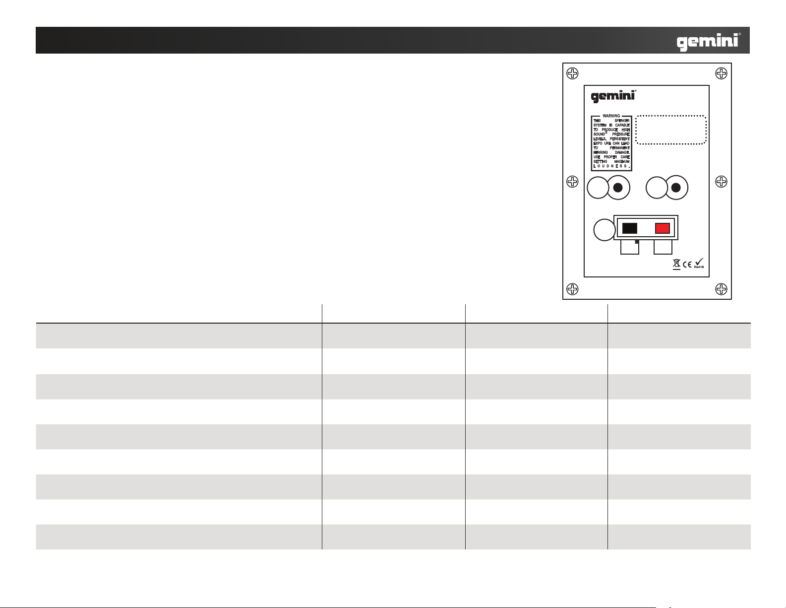
Note: 1260, 1585, and 3250 have similiar back panels.
Nota: 1260, 1585 y 3250 tienen paneles traseros similares.
Note: 1260, 1585 et 3250 disposent d’une face arrière identique.
Wichtig: 1260, 1585 und 3250 haben identische Rückseiten.
Specications GSM-1260 GSM-1585 GSM-3250
Frequency Response
Respuesta Frecuencia | Bande passante | Frequenzgang
50Hz ~ 20kHz 40Hz ~ 20kHz 35Hz ~ 20kHz
Dimensions
Dimensiones | Dimensions | Abmessungen
16.02 x 11.93 x 23.35 in
(407x 303x 593 mm)
18.86x 13.90x 28.46 in
(479x 353x 723 mm)
18.86x 13.9x 43.43 in
(479x 353x 1103 mm)
Net Weight
Peso Neto | Poids net | Gewicht
24 lbs. (10.9 kg) 38.7 lbs. (17.6 kg) 56.1 lbs. (25.5 kg)
Piezo Horn
Trompeta Piezo | Moteur à pavillon | Piezohorn
10” x 4” horn, (3) 3” Piezo 15” x 5” horn, (4) 3” Piezo 15” x 5” horn, (4) 3” Piezo
Low Frequency Driver
Altavoz de graves | Haut-parleur Basses | Bass-Chassis
12“ 15” (2)15”
Input
Entrada | Entrée | Eingang
Terminal Cup & (2) 1/4” Terminal Cup & (2) 1/4” Terminal Cup & (2) 1/4”
Impedance
Impedancia | Impedance | Impedanz
8Ω 8Ω 4Ω
Peak Power
Potencia de pico | Peak | Peak
400W 700W 1200W
RMS
RMS | RMS | RMS
100W 175W 300W
DESIGNED AND ENGINEERED IN USA BY GEMINI,
A DIVISION OF GCI TECHNOLOGIES, MANUFACTURED IN CHINA
Serial Number
GSM-1260
12” Loudspeaker, 100W RMS, 400W peak power
1 2
3

INTRODUCTION:
Congratulations on your purchase of a GSM-SERIES speaker, engineered & manufactured by
Gemini Sound Products. This state of the art speaker is backed up by a one-year warranty.
CAUTIONS:
1. Read all operating instructions before using this equipment.
2. To reduce the risk of electrical shock, do not open the unit. There are NO USER REPLACEABLE
PARTS INSIDE. Please refer servicing to a qualied Gemini Sound Products service technician.
3. Do not expose this unit to direct sunlight or to a heat source such as a radiator or stove.
4. This unit should be cleaned only with a damp cloth. Avoid solvents or other cleaning detergents.
5. When moving this equipment, it should be placed in its original carton and packaging. This will
reduce the risk of damage during transit.
6. DO NOT EXPOSE THIS UNIT TO RAIN OR MOISTURE.
7. DO NOT USE ANY SPRAY CLEANER OR LUBRICANT ON ANY CONTROLS OR SWITCHES.
CONNECTIONS:
PLEASE NOTE IT IS VERY IMPORTANT THAT YOUR AMPLIFIER HAS MATCHED POWER RAT-
INGS!
Make sure your equipment is completely OFF. Lower ALL VOLUME, LEVEL, & GAIN controls before
connecting the speaker.
1. Use a 1/4” SPEAKER CABLE from your AMPLIFIER LINE OUTPUT to connect to your speaker’s
1/4” INPUT JACK (1).
2. Another way to connect your AMPLIFIER to your speaker is through the TERMINAL CUP (3).
Use the PUSH-BUTTON CONNECTORS to connect the POSITIVE (+) and NEGATIVE (-) ends of a
standard SPEAKER WIRE with a 12-GAUGE minimum thickness from your AMPLIFIER LINE OUT-
PUT to your speaker’s TERMINAL CUP (3).
3. You can also use the 1/4” AUXILIARY OUTPUT JACK (2) to CHAINLINK an additional speaker
using a 1/4” SPEAKER CABLE.
OPERATION:
The speakers can be used in pairs for a NORMAL setup, or in groups of four when CHAIN-LINKED
together.
NORMAL SETUP:
1. Now turn on your MIXER or other signal source.
2. Then turn on your AMPLIFIER and increase the VOLUME or GAIN control as recommended by
the AMPLIFIER’s manual.
3. Start playing from your TURNTABLE, CD PLAYER, MIC, etc. and adjust the volume controls from
your mixer to a reasonable level.
CHAIN-LINK:
Only 1 additional speaker can be added to each speaker in a CHAINLINK setup. Connect your
speakers rst then follow the steps for a NORMAL setup, your AMPLIFIER should compensate for
the extra speakers.
INTRODUCCIÓN:
Felicitaciones en su compra de un sistema del altavoz de la GSM-SERIE, dirigido y fabricado por
los Productos de Gemini Sound. Este altavoz avanzado es sostenido por una garantía de tres
años.
PRECAUIONES:
1. Deberán leerse todas las instrucciones de operación antes de usar el equipo.
2. Para reducir el riesgo de shock eléctrico, no abra esta unidad. No contiene PIEZAS REEMPLA-
ZABLES POR EL USUARIO. Por favor, reera el servicio a un técnico de servicio calicado.
No devuelva el aparato a la tienda donde lo compró.
3. No exponga la unidad a la luz solar directa ni a una fuente de calor, por ejemplo, un radiador o
estufa.
4. Esta unidad sólo deberá limpiarse con un paño húmedo. Evite el uso de disolventes u otros
detergentes de limpieza.
5. Para mover este equipo, colóquelo en la caja y empaque original, a n de reducir el riesgo de
daños durante el transporte.
6. NO DEJE ESTA UNIDAD EXPUESTA A LLUVIA O HUMEDAD.
7. NO USE LIMPIADORES DE ROCÍO O LUBRICANTES EN CUALESQUIER CONTROLES O
INTERRUPTORES.
CONEXIONES:
¡NOTA ES POR FAVOR MUY IMPORTANTE QUE SU AMPLIFICADOR HA EMPAREJADO GRADOS
DE ENERGÍA!
Se cerciora de su equipo está totalmente APAGADO y también más bajo TODO el VOLUMEN,
NIVEL, y CONTROLES del AUMENTO y antes de conectar el altavoz.
1. Utilice un 1/4” SPEAKER CABLE de su línea del AMPLIFIER LINE OUTPUT para conectar con
su 1/4” INPUT JACK (1) de los altavoces .
2. Otra manera de conectar su AMPLIFICADOR con su altavoz es la TERMINAL CUP. Utilice los
PUSH-BUTTON CONNECTORS para conectar el POSITIVO (+) y los extremos NEGATIVOS (-) de
un SPEAKER WIRE con un grueso mínimo 12-GAUGE de su línea del AMPLIFIER LINE OUTPUT a
su TERMINAL CUP (3) de los altavoces.
3. Usted puede también utilizar el CADENA-ACOPLAMIENTO adicional del 1/4” AUXILIARY OUT-
PUT JACK (2) un altavoz adicional usando un 1/4” SPEAKER CABLE.
INSTRUCCIONES DE FUNCIONAMIENTO:
Los altavoces se pueden utilizar en los pares para una disposición NORMAL, o en grupos de cua-
tro cuando CADENA-ESTA’N ligados juntos.
DISPOSICIÓN NORMAL:
1. Ahora dé vuelta encendido al su MEZCLADOR o a la otra fuente de la señal.
2. Entonces gire su AMPLIFICADOR y aumente el VOLUMEN o GANE el control según lo recomen-
dado por el manual del dueño de los AMPLIFICADORES.
3. Comience a jugar de su PLACA GIRATORIA, LECTOR DE CD, MIC, ETC. y ajuste los controles
de volumen de su mezclador a un nivel razonable.
CADENA-ACOPLAMIENTO:
Solamente 1 altavoz adicional se puede agregar a cada altavoz en una disposición del ACO-
PLAMIENTO de CADENA. Conecte sus altavoces primero entonces siguen los pasos para una
disposición NORMAL, su AMPLIFICADOR debe compensar para los altavoces adicionales.
English & Español
2
 Loading...