


OPERATIONS MANUAL
BEDIENUNGSHANDBUCH
MANUAL DEL OPERADOR
MANUEL D’INSTRUCTIONS
UF-I064
UF-I264 M, H & L
UF-2064
UF-8264
PROFESSIONAL UHF MICROPHONE SYSTEMS
PROFESSIONELLE UHF MIKROPHON SYSTEME
SISTEMAS DE FRECUENCIA UHF PROFESIONALES DEL MICRÓFONO SYSTÈMES À FRÉQUENCE UHF PROFESSIONNELS DE MICROPHONE
MULTI LANGUAGE INSTRUCTIONS:
English............................................................................................................... |
Page 2 |
Deutsch............................................................................................................. |
Page 7 |
Español............................................................................................................ |
Page 10 |
Francais.......................................................................................................... |
Page 13 |
(1)

uf SERIES
RECEIVERS:
UF-1064
UF-1264
UF-2064
UF-8264
FM-64 MICROPHONE |
FB-64 TRANSMITTER |
(2)

FREQUENCY CHARTS:
USA 790-806 MHZ:
|
GROUP 1 |
GROUP 2 |
GROUP 3 |
GROUP 4 |
GROUP 5 |
GROUP 6 |
GROUP 7 |
GROUP 8 |
CHANNEL 1 |
790.375MHz |
798.375MHz |
790.750MHz |
799.125MHz |
790.250MHz |
798.125MHz |
790.875MHz |
798.750MHz |
CHANNEL 2 |
791.125MHz |
799.875MHz |
791.625MHz |
800.250MHz |
791.500MHz |
799.375MHz |
791.875MHz |
799.625MHz |
CHANNEL 3 |
792.125MHz |
800.875MHz |
792.750MHz |
801.375MHz |
792.375MHz |
800.375MHz |
792.625MHz |
800.750MHz |
CHANNEL 4 |
793.250MHz |
801.625MHz |
793.875MHz |
802.125MHz |
793.000MHz |
801.125MHz |
793.625MHz |
801.500MHz |
CHANNEL 5 |
794.250MHz |
802.750MHz |
794.625MHz |
803.375MHz |
794.375MHz |
802.250MHz |
794.875MHz |
802.875MHz |
CHANNEL 6 |
795.125MHz |
803.875MHz |
795.625MHz |
804.250MHz |
795.250MHz |
803.125MHz |
795.750MHz |
803.500MHz |
CHANNEL 7 |
796.250MHz |
804.750MHz |
796.875MHz |
805.125MHz |
796.375MHz |
804.375MHz |
796.750MHz |
804.875MHz |
CHANNEL 8 |
797.375MHz |
805.375MHz |
797.750MHz |
805.875MHz |
797.125MHz |
805.500MHz |
797.625MHz |
805.750MHz |
GERMANY 794-813 MHZ:
|
GROUP 1 |
GROUP 2 |
CHANNEL 1 |
794.375MHz |
803.750MHz |
CHANNEL 2 |
795.375MHz |
805.500MHz |
CHANNEL 3 |
796.500MHz |
806.750MHz |
CHANNEL 4 |
797.625MHz |
807.750MHz |
CHANNEL 5 |
798.750MHz |
808.875MHz |
CHANNEL 6 |
799.875MHz |
809.875MHz |
CHANNEL 7 |
801.250MHz |
811.125MHz |
CHANNEL 8 |
802.500MHz |
812.125MHz |
FRANCE/UK 854.25-865 MHZ:
|
GROUP 1 |
GROUP 2 |
CHANNEL 1 |
854.375MHz |
858.500MHz |
CHANNEL 2 |
854.875MHz |
858.875MHz |
CHANNEL 3 |
855.500MHz |
859.375MHz |
CHANNEL 4 |
855.875MHz |
860.125MHz |
CHANNEL 5 |
856.500MHz |
860.750MHz |
CHANNEL 6 |
857.125MHz |
861.250MHz |
CHANNEL 7 |
857.750MHz |
861.500MHz |
CHANNEL 8 |
858.125MHz |
861.875MHz |
GROUP 3 |
GROUP 4 |
GROUP 5 |
GROUP 6 |
GROUP 7 |
GROUP 8 |
794.750MHz |
804.125MHz |
794.875MHz |
804.875MHz |
795.125MHz |
805.250MHz |
795.625MHz |
805.750MHz |
795.875MHz |
806.125MHz |
796.250MHz |
806.375MHz |
796.750MHz |
807.125MHz |
797.125MHz |
807.250MHz |
797.375MHz |
807.500MHz |
797.875MHz |
808.125MHz |
798.125MHz |
808.500MHz |
798.500MHz |
808.750MHz |
798.875MHz |
809.250MHz |
799.250MHz |
809.500MHz |
799.500MHz |
809.750MHz |
800.125MHz |
810.125MHz |
800.375MHz |
810.500MHz |
800.625MHz |
810.750MHz |
801.500MHz |
811.375MHz |
801.750MHz |
811.625MHz |
802.250MHz |
811.750MHz |
802.750MHz |
812.375MHz |
803.250MHz |
812.500MHz |
803.500MHz |
812.750MHz |
GROUP 3 |
GROUP 4 |
GROUP 5 |
GROUP 6 |
GROUP 7 |
GROUP 8 |
854.500MHz |
859.250MHz |
854.625MHz |
859.500MHz |
854.750MHz |
859.625MHz |
855.125MHz |
859.750MHz |
855.250MHz |
859.875MHz |
855.375MHz |
860.250MHz |
855.625MHz |
860.375MHz |
855.750MHz |
860.500MHz |
856.125MHz |
860.625MHz |
856.250MHz |
860.875MHz |
856.375MHz |
861.125MHz |
856.625MHz |
861.375MHz |
856.750MHz |
861.625MHz |
856.875MHz |
861.750MHz |
857.250MHz |
863.250MHz |
857.375MHz |
863.375MHz |
857.500MHz |
863.500MHz |
857.625MHz |
863.625MHz |
857.875MHz |
863.750MHz |
858.250MHz |
864.250MHz |
858.375MHz |
864.375MHz |
858.625MHz |
864.500MHz |
858.750MHz |
864.625MHz |
859.125MHz |
864.750MHz |
(3)
INTRODUCTION:
Congratulations on your purchase of a GEMINI wireless system. This state of the art unit includes all the latest features backed by a three year limited warranty. Prior to use, we suggest that you carefully read the instructions.
FEATURES:
•UF-1064 M includes UF-1064 receiver & FM-64 handheld microphone
•UF-1064 H includes UF-1064 receiver, FB-64 belt pack transmitter with mic/line switch
&HSM-X3 headset mic with mini XLR
•UF-1064 L includes UF-1064 receiver, FB-64 belt pack transmitter with mic/line switch
&LAV-X3 lavalier mic with mini XLR
•UF-1264 M includes UF-1264 diversity receiver & FM-64 handheld microphone
•UF-1264 H includes UF-1264 diversity receiver, FB-64 belt pack transmitter with mic/line switch & HSM-X3 headset mic with mini XLR
•UF-1264 L includes UF-1264 diversity receiver, FB-64 belt pack transmitter with mic/line switch & LAV-X3 lavalier mic with mini XLR
•UF-2064 M includes UF-2064 dual receiver, FM-64 handheld microphone
•UF-2064 H includes UF-2064 dual receiver, 2 FB-64 belt pack transmitters with mic/line switches, & 2 HSM-X3 headset mics with mini XLR
•UF-2064 L includes UF-2064 dual receiver, 2 FB-64 belt pack transmitters with mic/line switches, & 2 LAV-X3 lavalier mics with mini XLR
•UF-2064 MH includes UF-2064 dual receiver, FB-64 belt pack transmitter with mic/line switch FM-64 handheld microphone, & HSM-X3 headset mic with mini XLR
•UF-2064 HL includes UF-2064 dual receiver, 2 FB-64 belt pack transmitters with mic/line switches, HSM-X3 headset mic with mini XLR & LAV-X3 lavalier mic with mini XLR
•UF-2064 ML includes UF-2064 dual receiver, FB-64 belt pack transmitter with mic/line switch & LAV-X3 lavalier mic with mini XLR
•UF-8264 M includes UF-8264 diversity receiver & FM-64 handheld microphone 64 band UHF synthesizer controlled frequencies
•UF-8264 H includes UF-8264 diversity receiver, FB-64 belt pack transmitter with mic/line switch & HSM-X3 headset mic with mini XLR
•UF-8264 L includes UF-8264 diversity receiver, FB-64 belt pack transmitter with mic/line switch & LAV-X3 lavalier mic with mini XLR
•Phase locked loop (PLL) circuitry
•Super high sensitivity with extremely low noise transmission & reception
•Stable & quality SMT assembled PCB module
•Power & RF LEDs
•Squelch control
•UF-8264 comes in hard plastic ABS carry case
•FM-64 has a uni-directional dynamic unit microphone
•HSM-X3 has an electret condenser unit microphone
•LAV-X3 has an electret condenser unit microphone
•FM-64/FB-64 has a rechargeable input for battery recharging
CAUTIONS:
1.All operating instructions should be read before using this equipment.
2.To reduce the risk of electrical shock, do not open the unit. THERE ARE NO USER REPLACEABLE PARTS INSIDE. Please refer servicing to a qualified service technician.
3.Do not expose this unit to direct sunlight or to a heat source such as a radiator or stove.
4.Dust, dirt and debris can interfere with the performance of this unit. Make an effort to keep the unit away from dusty, dirty environments, and cover the unit when it is not in use. Dust it regularly with a soft, clean brush.
5.When moving this equipment, it should be placed in its original carton and packaging. This will reduce the risk of damage during transit.
6.DO NOT EXPOSE THIS UNIT TO RAIN OR MOISTURE.
7.DO NOT USE ANY SPRAY CLEANER OR LUBRICANT ON ANY CONTROLS OR SWITCHES.
8.REMEMBER, ANY CHANGES MADE TO THE UNIT WITHOUT AUTHORIZATION FROM GEMINI WILL VOID YOUR WARRANTY.
FCC RULES AND REGULATIONS:
This device complies with part 15 of the FCC rules. Operation is subject to the following two conditions: (1)This device may not cause harmful interference and (2) This device must accept any interference received, including interference that may cause undesired operation.
Notice: The changes or modifications not expressly approved by the party responsible for compliance could void the user’s authority to operate the equipment.
Important note, to comply with the FCC RF exposure compliance requirements, no change to the antenna or the device is permitted. Any change to the antenna or the device could result in the device exceeding the RF exposure requirements and void user’s authority to operate the device.
UF WIRELESS SYSTEMS:
The UF wireless systems are high quality audio products that provide excellent performance under most operating conditions. The different systems available all operate with UHF high band frequencies.
Frequency ranges: USA: 790-806 MHz, France/UK 854-865 MHz, & Germany: 794-813 MHz, See page 3 for frequency chart.
WIRELESS NOTES:
•Before setting up, make sure that the transmitter and receiver are tuned to the same frequency.
•Do not use two transmitters in the same frequency. Use good quality batteries to avoid the damage resulting from a defective leaking battery.
•Turn the volume control on the receiver to adjust receiver output level to match input level requirements of an audio mixer or amplifier.
•While checking sound, move the transmitter around the area where you use the system to look for dead spots. If you find any dead spot, change the receiver position. If it does not work, avoid such places.
•To avoid interference, do not put the receiver too near metal object and avoid obstructions between transmitter and receiver.
•Avoid the interference from TV, radio, other wireless appliances and etc.
FUNCTION DESCRIPTIONS:
UF RECEIVERS:
These stationary receivers are for use with our 64-channel selectable transmitters. The receiver operates in UHF band frequency with PLL synthesized control. Powered by 12V DC.
(1) POWER BUTTON: Push the POWER button to turn the receiver on & off.
(2)CHANNEL SELECTOR: 64 different selectable can be selected used by rotating the selector(s) or knobs.
(2b) SET: Push the SET button to lock the selected group and channel.
(2c) GR/CH LED: These LED indicates the power is on, and display which group & channel is on.
(3)POWER INDICATOR: The indicator LED lights when the receiver is ready to operate.
(4)RF LEVEL INDICATORS: These LED lights to indicate that signal is being received. For the UF-1264 the RF LED show the diversity RF signal that is being used Aor B.
For the UF-2064 the RF LEd display which MIc is being received MIC 1 or 2
For the UF-8264 the RF LED is a 5 level RF LEVEL meter that displays the signal strength.
(5)LEVEL CONTROL: Rotary controls adjust the receiver’s output level from the microphone to line level for matching the input sensitivity of the mixer or amplifier.
(6)ANTENNA: Fixed-length UHF antenna permanently mounted either on the front or on rear panel.
(7)DC OUT: Connect the supplied cable to the receiver and the microphone, and it takes around 10 hours to charge.
NOTE: THE UF-1064, UF1264, & UF2064 ARE THE ONLY MODELS THAT RECHARGE BATTERIES.
(8)UNBALANCED OUTPUT: Unbalanced 1/4” mono jack audio output provides unbalanced low-impedance output
(9)BALANCED OUTPUT: 3-pin XLR connector provides balanced lowimpedance output
(10) SQUELCH ADJ.: The squelch adjusts the output level to prevent from the external noise. Setting the squelch too high will reduce the range of the system. Set the squelch to minimum before turning the receiver on.
(11) DC IN: Input connector for the supplied AC adapter.
FM-64 HANDHELD MICROPHONE:
The handheld microphone operates in UHF band frequency with PLL synthesized control. UHF 64 preprogramed selectable frequencies to avoid interference. Uni-directional dynamic or uni-directional electret condenser capsules with different characters for various choices. Use 1.5V x 2 AA size rechargeable or regular batteries for low operating cost.
(1)GRILLE: Protects the microphone capsule and helps reduce breath sounds and wind noise. The grille for the various microphone capsules differ in appearance.
(2)LOW BATTERY LED: LED indicates battery status. Switching the power to “ON”, the LED flashing once indicates that the transmitter has sufficient power. If the LED stays on, it indicates that the battery has insufficient power and should be changed soon. If the status LED fails to flash, the battery is either dead or not positioned correctly, and you should correct the positioning or change the battery.
(3)ON/OFF SWITCH: Turns transmitter power on and off.
(4)BATTERY COMPARTMENT: Insert two AA batteries into the compartment and make sure that the polarity of batteries is correct.
(5) CHANNEL SELECTOR: Changes transmitter channel setting.
(6)BATTERY COVER: Push to expose battery compartment and channel selector.
(7)COLOR CLIP: This color clip helps to identify the frequency for multichannel operation.
(8)CHARGING INPUT: The inserted rechargeable batteries can be charged by using the supplied DC-plug cable connection to DC Out on the receiver. It takes up to 10 hours for charging.
(4)
FB-64 BODYPACK TRANSMITTER:
The bodypack transmitter operates in UHF band frequency with PLL synthesized control. UHF 64 preprogrammed selectable frequencies to avoid interference. Various uni-directional electret condenser capsule options. Use 1.5V x 2 AA size batteries for low operating cost.
(1)INPUT CONNECTOR: Mini XLR microphone connector, connect the headset or lavalier here.
(2)ON/OFF SWITCH: Turns transmitter power on and off.
(3)LOW BATTERY LED: LED indicates battery status. Switching the power to “ON”, the LED flashing once indicates that the transmitter has sufficient power. If the LED stays on, it indicates that the battery has insufficient power and should be changed soon. If the status LED fails to flash, the battery is either dead or not positioned correctly, and you should correct the positioning or change the battery.
(4)MIC/LINE SELECTOR (optional for use with mini XLR connector):
This switch sets the audio input either to microphone level or line level.
(5)ANTENNA: Permanently connected, helical antenna.
(6)CHANNEL SELECTOR: Changes transmitter channel setting.
(7)GAIN: The rotary control adjusts the sensitivity of the transmitter’s audio to the level of the connected lapel microphone or instrument.
(8)MIC. UNIT: The uni-directional electret condenser unit features the wide frequency response for warm, rich bass and clear sound.
(9)TIE CLIP: Use to clip onto shirt or tie. for free movement.
(10)CABLE: Connect the CABLE to the mini XLR connector to connect to the transmitter
(11)BATTERY COMPARTMENT: Insert two AA batteries into the compartment and make sure that the polarity of batteries is correct.
(12)CHARGING INPUT: The inserted rechargeable batteries can be charged by using the supplied DC-plug cable connection to DC Out on
the receiver. It takes up to 10 hours for charging.
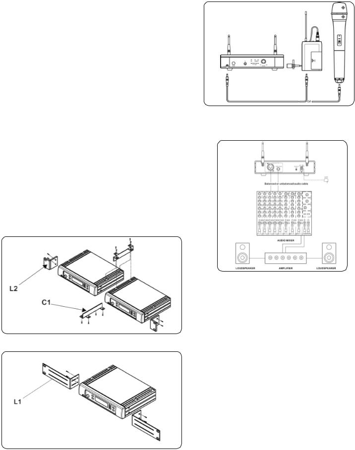
To combine two receivers in a 19" standard rack by using 2 short L type plastic racks (L2) and 2 metal connecting plates (C1). (Each system includes a L2 and a C1.)
BASIC CONNECTIONS:
Connect the receiver output to the audio mixer or amplifier input, using a standard audio cable with XLR connectors or 1/4” phone plugs. Never use the balance & unbalanced outputs at the same time! This may cause signal loss or increased noise.
To mount a receiver in a 19" standard rack by using 2 long L type metal racks (L1).
SETTING UP:
Prior to setting up, check that the transmitter and receiver are tuned to the same frequency. Two or above transmitters operating in the same frequency can not be used at the same time and area, so please select the different frequencies which can be used simultaneously at local area.
CONNECTING THE RECEIVER TO POWER:
•Point the antennas upward.
•Check that the voltage of the supplied AC adapter (AC110 or AC220) conforms to the voltage available in local area. Using the wrong AC adapter may cause irreparable damage to the unit.
•Plug the feeder cable of the supplied AC adapter into DC IN socket on the receiver. Then plug the AC adapter into a power outlet.
NOTE: THE UF-8264 RECIEVERS CANNOT BE COMBINED WITH EACH OTHER.
CHARGING CONNECTING DIAGRAM:
Connect the supplied DC cable to the receiver and the microphone, and it takes around 10 hours to charge and the LED of transmitter is flashing all the time.
CONNECTING THE RECEIVER TO AN AUDIO MIXER OR AN AMPLIFIER:
In order to make sure the sound quality and avoid distortion, please adjust the volume level according to following instructions.
INSERTING BATTERIES INTO THE HANDHELD / BODYPACK TRANSMITTER:
•Push to open the battery cover and insert batteries into the battery compartment conforming to the polarity (+)(-) marks. The transmitter can not work with incorrectly inserted batteries.
•When push the ON/OFF switch to “ON” to switch the power on, the LED will flash momentarily. If the battery has sufficient power, the LED flashes once. If the LED stayed on, it indicates that the battery has insufficient power and should be changed soon. If the status LED fails to flash, the battery is either dead or not positioned correctly, and you should correct the positioning or change the battery.
•Push back the battery cover to click it shut.
(5)
 Loading...