


CDM-500
P r o f e s s i o n a l d j s t a t i o n
P R O F E S S I O N E L L E D J S T A T I O N
E S T A C I O N P R O F E S I O N A L P A R A D J
D J S Y S T È M E C O M P A C T
Worldwide Offices
USA: |
UK: |
Spain: |
France: |
Germany: |
|
|
|
|
|
|
|
|
|
|
|
Gemini Sound Products Corp. |
Gemini Sound Products LTD |
Gemini Sound Products S.A. |
GSL France |
Gemini Sound |
|
|
|
|
|
|
|
|
|
|
|
Worldwide Headquarters |
Unit C4 Hazleton |
Rosellon 516 local |
1, Allée d' Effiat, |
Products GmbH |
|
|
|
|
|
|
|||||
120 Clover Place |
Industrial Estate, |
08026 Barcelona |
Parc de l'événement |
Liebigstrasse 16 |
|
|
|
|
|
|
|||||
|
|
|
|
|
|
||||||||||
Edison, New Jersey 08837 |
Waterlooville P08 9JU |
Ph: + 34 93 436 37 00 |
F-91160 Longjumeau |
85757 Karlsfeld |
|
|
|
|
|
|
|||||
Ph: 732.738.9003 |
Ph: +44 (0)87 087 00880 |
Fax: + 34 93 347 69 61 |
Ph: + 33 1 69 79 97 70 |
Ph: + 49 8131 39171-0 |
|
|
|
|
|
|
|||||
Fax: 732.738.9006 |
Fax: +44 (0)87 087 00990 |
|
Fax: + 33 1 69 79 97 80 |
Fax: + 49 8131 39171-8 |
|
|
|
|
|
|
|||||
In the USA: If you experience problems with this unit, please go to http://www.geminidj.com/support.html or call 1-732-738-9003 for Gemini Customer Service. Do not attempt to return this equipment to your dealer. Gemini stands behind their products with a 1 year limited warranty on all audio products. For larger images & detailed specs visit our website @ http://www.geminidj.com. WE ARE NOT RESPONSIBLE FOR TYPOGRAPHICAL ERRORS OR OMISSIONS. WE RESERVE THE RIGHT TO CHANGE WITHOUT NOTICE. Parts of the design of this product may be protected by worldwide patents. Information in this manual is subject to change without notice and does not represent a commitment on the part of the vendor. Gemini Sound Products Corp. shall not be liable for any loss or damage whatsoever arising from the use of information or any error contained in this manual. No part of this manual may be reproduced, stored in a retrieval system or transmitted, in any form or by any means, electronic, electrical, mechanical, optical, chemical, including photocopying and recording, for any purpose without the express written permission of Gemini Sound Products Corp. It is recommended that all maintenance and service on this product is performed by Gemini Sound Products Corp. or its authorized agents. Gemini Sound Products Corp. will not accept liability for loss or damage caused by maintenance or repair performed by unauthorized personnel.

C A U T I O N
PLEASE READ BEFORE USING APPLIANCE, IMPORTANT WARNING & SAFET Y INSTRUCTIONS! RISK OF ELECTRICAL SHOCK DO NOT OPEN!
CAUTION: This product satisfies FCC regulations when shielded cables and connectors are used to connect the unit to other equipment. To prevent electromagnetic interference with electric appliances such as radios and televisions, use shielded cables and connectors for connections.
The exclamation point within an equilateral triangle is intended to alert the user to the presence of important operating and maintenance (servicing) instructions in the literature accompanying the appliance.
The lightning flash with arrowhead symbol, within an equilateral triangle, is intended to alert the user to the presence of uninsulated "dangerous voltage" within the product's enclosure that may be of sufficient magnitude to constitute a risk of electric shock to persons.
READ INSTRUCTIONS: All the safety and operating instructions should be read before the product is operated.
RETAIN INSTRUCTIONS: The safety and operating instructions should be retained for future reference.
HEED WARNINGS: All warnings on the product and in the operating instructions should be adhered to.
FOLLOW INSTRUCTIONS: All operating and use instructions should be followed.
CLEANING: The product should be cleaned only with a polishing cloth or a soft dry cloth. Never clean with furniture wax, benzine, insecticides or other volatile liquids since they may corrode the cabinet.
ATTACHMENTS: Do not use attachments not recommended by the product manufacturer as they may cause hazards.
WATER & MOISTURE: Do not use this product near water, for example, near a bathtub, wash bowl, kitchen sink, or laundry tub; in a wet basement; or near a swimming pool; and the like.
ACCESSORIES: Do not place this product on an unstable cart, stand, tripod, bracket, or table. The product may fall, causing serious injury to a child or adult, and serious damage to the product. Use only with a cart, stand, tripod, bracket, or table recommended by the manufacturer, or sold
with the product. Any mounting of the product should follow the manufacturer's instructions, and should use a mounting accessory recommended by the manufacturer.
CART: A product and cart combination should be moved with care. Quick stops, excessive force, and uneven surfaces may cause the product and cart combination to overturn. SEE FIGURE A.
VENTILATION: Slots and openings in the cabinet are provided for ventilation and to ensure reliable operation of the product and to protect it from overheating, and these openings must not be blocked or covered. The openings should never be blocked by placing the product on a bed, sofa, rug, or other similar surface. This product should not be placed in a builtin installation such as a bookcase or rack unless proper ventilation is provided or the manufacturer's instructions have been adhered to.
POWER SOURCES: This product should be operated only from the type of power source indicated on the marking label. If you are not sure of the type of power supply to your home, consult your product dealer or local power company.
LOCATION: The appliance should be installed in a stable location. NON-USE PERIODS: The power cord of the appliance should be unplugged from the outlet when left unused for a long period of time.
GROUNDING OR POLARIZATION:
-If this product is equipped with a polarized alternating current line plug (a plug having one blade wider than the other), it will fit into the outlet only one way. This is a safety feature. If you are unable to insert the plug fully into the outlet, try reversing the plug. If the plug should still fail to fit, contact your electrician to replace your obsolete outlet. Do not defeat the safety purpose of the polarized plug.
-If this product is equipped with a three-wire grounding type plug, a plug having a third (grounding) pin, it will only fit into a grounding type power outlet. This is a safety feature. If you are unable to insert the plug into the outlet, contact your electrician to replace your obsolete outlet. Do not defeat the safety purpose of the grounding type plug.
POWER-CORD PROTECTION: Power-supply cords should be routed so that they are not likely to be walked on or pinched by items placed upon or against them, paying particular attention to cords at plugs, convenience receptacles, and the point where they exit from the product.
OUTDOOR ANTENNA GROUNDING: If an outside antenna or cable system is connected to the product, be sure the antenna or cable system is grounded so as to provide some protection against voltage surges and built-up static charges. Article 810 of the National Electrical Code, ANSI/NFPA 70, provides information with regard to proper grounding of the mast and supporting structure, grounding of the lead-in wire to an antenna discharge unit, size of grounding conductors, location of antennadischarge unit, connection to grounding electrodes, and requirements for the grounding electrode. SEE FIGURE B.
LIGHTNING: For added protection for this product during a lightning storm, or when it is left unattended and unused for long periods of time, unplug it from the wall outlet and disconnect the antenna or cable system. This will prevent damage to the product due to lightning and power-line surges.
<2>
POWER LINES: An outside antenna system should not be located in the vicinity of overhead power lines or other electric light or power circuits, or where it can fall into such power lines or circuits. When installing an outside antenna system, extreme care should be taken to keep from touching such power lines or circuits as contact with them might be fatal.
OVERLOADING: Do not overload wall outlets, extension cords, or integral convenience receptacles as this can result in a risk of fire or electric shock. OBJECT & LIQUID ENTRY: Never push objects of any kind into this product through openings as they may touch dangerous voltage points or shortout parts that could result in a fire or electric shock. Never spill liquid of any kind on the product.
SERVICING: Do not attempt to service this product yourself as opening or removing covers may expose you to dangerous voltage or other hazards. Refer all servicing to qualified service personnel.
DAMAGE REQUIRING SERVICE: Unplug this product from the wall outlet and refer servicing to qualified service personnel under the following conditions:
-When the power-supply cord or plug is damaged.
-If liquid has been spilled, or objects have fallen into the product.
-If the product has been exposed to rain or water.
-If the product does not operate normally by following the operating instructions. Adjust only those controls that are covered by the operating instructions as an improper adjustment of other controls may result in damage and will often require extensive work by a qualified technician to restore the product to its normal operation.
-If the product has been dropped or damaged in any way.
-When the product exhibits a distinct change in performance, this indicates a need for service.
REPLACEMENT PARTS: When replacement parts are required, be sure the service technician has used replacement parts specified by the manufacturer or have the same characteristics as the original part. Unauthorized substitutions may result in fire, electric shock, or other hazards.
SAFET Y CHECK: Upon completion of any service or repairs to this product, ask the service technician to perform safety checks to determine that the product is in proper operating condition.
WALL OR CEILING MOUNTING: The product should not be mounted to a wall or ceiling.
HEAT: The product should be situated away from heat sources such as radiators, heat registers, stoves, or other products (including amplifiers) that produce heat.
DISPOSAL: This product shall not be treated as household waste. Instead it shall be handed over to the applicable collection point for the recycling of electrical and electronic equipment. By ensuring this product is disposed of correctly, you will help prevent potential negative consequences for the environment and human health, which could otherwise be caused by inappropriate waste handling of this product. The recycling of materials will help to conserve natural resources. For more detailed information about recycling of this product, please contact your local city office, your household waste disposal service or the shop where you purchased the product.

Face
|
25 |
26 |
25 |
|
|
|
|
|
|
|
|
|
|
|
|
|
1 |
|
|
27 |
28 |
29 |
|
27 |
|
|
|
|
|
|
22 |
21 |
23 |
2 |
|
3 |
5 |
|
6 |
|
|
|
|
|
|
|
|
|
|
|
|
|
|
7 |
8 |
4 |
13 |
14 |
12 |
|
|
|
|
|
|
|
|||
|
|
|
|
9 |
10 |
11 |
|
|
15 |
|
|
|
|
|
|
|
|||
|
|
|
|
|
|
|
16 |
|
|
30 |
30 |
31 |
33 |
31 |
|
18 |
|
|
|||
32 |
|
32 |
20 |
17 |
|
34 |
|
|
19 |
|
|
|
|
24
*To avoid confusion, only the right side of the controls are labeled.
|
1. |
LCD Display |
10. |
Loop Out |
19. |
Play/Pause Button |
28. |
Mic Volume Level Control |
|
2. |
Open/Close Button |
11. |
Reloop |
20. |
Jog Wheel |
29. |
Cue Volume Level Control |
|
3. |
Program |
12. |
Track Skip Forward |
21. |
LED VU Meter |
30. |
High Band EQ |
|
4. |
Time Selection |
13. |
Track Skip Backward |
22. |
Channel 1 Fader |
31. |
Mid Band EQ |
|
5. |
Pitch Bend +/- |
14. |
+10 Track Skip |
23. |
Channel 2 Fader |
32. |
Low Band EQ |
Parts Checklist: |
6. Pitch On/Off |
15. |
Direct Track Access Buttons |
24. |
Crossfader |
33. |
Master Volume Control |
|
CDM-500 Unit |
7. Single/Continuous Play |
16. |
Jog Mode Selector |
25. |
Device Input Selector |
34. |
Fader Start Selector |
|
AC Power Cable |
8. Repeat |
17. |
Pitch Control |
26. |
Cue Device Selector |
|
|
|
Manual & Warranty Information |
9. Loop In |
18. |
Cue Button |
27. |
Channel Gain Control |
|
|
|
<3>

Back
|
|
|
47 |
|
|
46 |
|
36 |
38 |
39 |
|
|
|
|
|
37 |
43 |
42 |
40 |
41 |
44 |
45 |
|
35 |
|
|
Front |
49 |
51 |
|
52 |
48 |
50 |
|
|
|
|
|
|
|
35. |
AC Inlet for Power Cable |
41. |
Phono 1/Line 1 Switch |
47. |
XLR Mic Input |
|
36. |
Fuse |
42. |
Line 2 Input |
48. |
CD Tray 1 |
|
37. |
Power Switch |
43. |
Phono 2/Line 2 Switch |
49. |
Tray 1 Illumination LED |
|
38. |
Voltage Selector Switch |
44. |
Record Output |
50. |
CD Tray 2 |
|
39. |
Ground Terminal |
45. |
Master Output |
51. |
Tray 2 Illumination LED |
|
40. |
Line 1 Input |
46. |
1/4” (6.35mm) Mic Input |
52. |
1/4” (6.35mm) Headphone Jack |
|
<4>

CDM-500 PROFESSIONAL DJ STATION
INTRODUCTION:
Congratulations on your purchase of a Gemini CDM-500 Integrated DJ System! The CDM-500 is an all-in-one solution for DJs looking for a package which combines the features of a Dual Deck CD player with that of an audio mixer. The CDM-500 is backed by a 1 year limited warranty* and is sure to provide years of reliable service with the proper care and maintenance.
FEATURES:
-Dual tray-loading CD player with Integrated 2-Channel Mixer
-Audio CD and CD-R compatible
-Anti-Shock using RAM Buffer Memory
-Instant-Start and Cue with preview
-Single/Continuous play modes
-Fader-Start capability
-Seamless loop per side with reloop
-Pitch bend via Jog wheel or buttons
-Three time display modes
-Frame accurate search
-Direct track access buttons
-Pitch control with range of +/- 12%
-+10 track button for quick navigation
-Fully programmable with repeat function
-LED VU Meter
-3-band EQ per channel w/Gain Controls
-¼" headphone output
-XLR and ¼" mic input
-Auxiliary Inputs for Phono or Line devices
CAUTIONS:
1.All operating instructions should be read before using this equipment.
2.To reduce the risk of electrical shock, do not open the unit. There are NO USER REPLACEABLE PARTS INSIDE. Please refer servicing to a qualified Gemini Sound Products service technician. In the USA: If you experience problems with this unit, please call 1 (732) 738-9003 for Gemini Customer Service. Do not attempt to return this equipment to your dealer.
3.Do not expose this unit to direct sunlight or to a heat source such as a radiator or stove.
4.This unit should be cleaned only with a damp cloth. Avoid solvents or other cleaning detergents.
5.When moving this equipment, it should be placed in its original carton and packaging. This will reduce the risk of damage during transit.
6.DO NOT EXPOSE THIS UNIT TO RAIN OR MOISTURE.
7.DO NOT USE ANY SPRAY CLEANER OR LUBRICANT ON ANY CONTROLS OR SWITCHES.
CONNECTIONS / SETUP:
1. AC INLET: The AC INLET (35), located on the rear of the unit, is the connector which accepts the POWER CORD (supplied) used to power the unit.
2. VOLTAGE SELECTOR SWITCH: The VOLTAGE SELECTOR SWITCH
(38) allows the unit to operate on either 115 or 230 volt 


 configurations, for worldwide operation. Prior to using the unit, make sure that this switch reflects the voltage supplied in your local-
ity.
3. FUSE: Located next to the AC INLET is a 250 V FUSE (36) to protect against electrical surges. To replace the fuse, first disconnect the POWER CORD, and place a flat head screwdriver into the groove
of the Fuse cap - turn it until the fuse holder is released. Simply put a new 250 V Fuse in the Fuse Holder, press down the Fuse Holder, and use a flat head screwdriver to lock it in place.
4. POWER SWITCH: The POWER SWITCH (37) turns the unit ON or OFF. Make sure the switch is in the ‘OFF’ position prior to making any connections.
5. LINE 1 INPUT AND PHONO 1/LINE 1 SWITCH: This input makes it
possible to connect an additional source to Channel 1 of the audio mixer portion of the unit. Plug your Phono or Line 
 device’s RCA connectors into the LINE 1 INPUT (40) and switch
the PHONO 1/LINE 1 SWITCH (41) to the appropriate position. If you are plugging in a Turntable, set the switch to PHONO; if you are using a Line Level device, set the switch to LINE.


 6. LINE 2 INPUT AND PHONO 2/LINE 2 SWITCH: This input makes
it possible to connect an additional source to Channel 2 of the audio mixer portion of the unit. Plug your Phono or Line
device’s RCA connectors into the LINE 2 INPUT (42) and switch
the PHONO 2/LINE 2 SWITCH (43) to the appropriate position. If you are plugging in a Turntable, set the switch to PHONO; if you are using a Line Level device, set the switch to LINE.
7. 1/4” MIC INPUT and XLR MIC INPUT: The 1/4” MIC
INPUT (46) and XLR MIC INPUT (47) accept standard Lo-Z and Hi-Z microphones using either 1/4” or XLR connectors. Only one microphone should be used at
once, and the MIC VOLUME LEVEL CONTROL (28) controls the level of the connected microphone.
8. GROUND TERMINAL: When using Turntables with the rear RCA inputs, it may be necessary to ground them to the GROUND TERMINAL (39), to eliminate hum. With the Power OFF, Simply fasten the grounding
forks underneath the GROUND TERMINAL (39).
<5>


 9. MASTER OUTPUT: The MASTER OUTPUT (45) passes a stereo unbalanced signal which is controlled by the MASTER VOLUME CONTROL
  (33). The MASTER OUTPUT (45) is typically used to drive your
Amplifier or Powered Speakers.


 10. RECORD OUTPUT: The RECORD OUTPUT (44) passes a stereo unbalanced signal which is unaffected by the MASTER VOLUME CONTROL (33). This is useful for connecting to a recording device, as if the need arises to increase the MASTER VOLUME CONTROL (33), it will not be reflect-
ed in the recording.
11. 1/4” HEADPHONE JACK: The 1/4” HEADPHONE JACK (52) is located
on the front panel, and accepts headphones with a 1/4” (6.35mm) jack. The volume of the headphones is controlled by the CUE
VOLUME LEVEL CONTROL (29).


 12. CD TRAY 1: CD TRAY 1 (48), on the front left
  side, is the drawer used to load and unload Compact Discs. Discs inserted on this side will always be controlled by the
left side CD player controls, and the audio signal will always be controlled by CHANNEL 1 of the Audio Mixer portion of the unit.

 13. CD TRAY 2: CD TRAY 2 (50), on the front right
  side, is the drawer used to load and unload Compact Discs. Discs inserted on this side will always be controlled by the
right side CD player controls, and the audio signal will always be controlled by CHANNEL 2 of the Audio Mixer portion of the unit.
14. TRAY ILLUMINATION LEDS: The blue TRAY ILLUMATION LEDS (49) and
(51) illuminate the CD TRAYS when they are in the open position. This is useful for working in dimly lit areas. The TRAY ILLUMINATION LEDS also light when there is no disc detected in the drive.
FUNCTIONS:
1. LCD DISPLAY: The LCD DISPLAY (1) is used to visually show the parameters relating to CD playback. This includes the track number, time display, pitch percentage, play mode, as
well as a bar graph indicating the position during playback.
2. OPEN/CLOSE BUTTON: The OPEN/CLOSE BUTTONS (2) are used to
control their respective CD trays. Note that in order to Open a CD tray, playback must first be paused or stopped on that side.
3. PROGRAM: The PROGRAM (3) Button is used to create a sequence of tracks which will be played on that respective side of the CD player.
a. To engage the program function, simply press PROGRAM (3) at any time. The unit will display the letter ‘P’ on screen, as well as the number 01.
b. At this prompt, use the DIRECT TRACK ACCESS BUTTONS (15) or the TRACK SKIP BUTTONS (12, 13, 14) to enter the first track that you want to add to the sequence.
c. Press PROGRAM (3) again, and the unit will display ‘P02’, indi cating the next track in sequence. Enter the next track that you want to add to the sequence. You may repeat this process
for up to 20 tracks.
d. When you are finished programming the sequence, simply press the PROGRAM (3) button again.
e. To play the Program, press PLAY/PAUSE (19).
f. To clear the Program, hold the PROGRAM (3) button down for
2seconds.
4.TIME SELECTION: The TIME SELECTION (4) button toggles the time display between Time Elapsed, Time Remaining, and Total Time
Remaining modes. Notice that this button also changes the bar graph display at the top of the LCD DISPLAY (1) to reflect the time mode.


 5. PITCH BEND: The PITCH BEND (5) function allows you to
  momentarily increase or decrease the speed and key of the currently playing music. When the PITCH BEND (5) buttons are released, the
pitch will return to the value displayed on the LCD DISPLAY (1).


 6. PITCH CONTROL: The PITCH CONTROL (17) allows the speed and key of the currently playing music to be increased or decreased in small incre-
ments, up to +/- 12%.


 7. PITCH ON/OFF: The PITCH ON/OFF (6) button must be set to the
 ‘ON’ position before the unit will respond to changes made with the PITCH CONTROL (17). The PITCH ON/OFF (6) button will illuminate when
it is in the ‘ON’ position, and the word ‘PITCH’ will be displayed above the Pitch Percentage on the LCD DISPLAY (1).
8. SINGLE/CONTINUOUS PLAY: The SINGLE/CONTINUOUS PLAY (7) mode


 button determines if the unit will pause after playing each track. By default, the unit is set to Continuous mode, which will play the entire disc without stopping. When the SINGLE/CONTINUOUS PLAY (7) mode button is pressed, the unit will display the word ‘SINGLE’ in the upper right cor-
ner of the respective LCD DISPLAY (1), and the unit will pause after the end of each track.
9. REPEAT: The REPEAT (8) button allows you repeat a single track, or


 repeat the entire disc. When the REPEAT (8) button is pressed once, the words ‘REPEAT 1’ will be displayed on the LCD Display (1), and it will repeat only the current track. When the REPEAT (8) button is pressed a second time, the words ‘REPEAT ALL’ will be displayed, and the unit will repeat the entire disc. Note that the SINGLE/CONTINUOUS PLAY (7) mode will still determine if the unit pauses at the end of each track.
10. TRACK SKIP FORWARD: TRACK SKIP FORWARD (12) button allows you
to advance to the next track.
 11. TRACK SKIP BACKWARD: TRACK SKIP BACKWARD (13) button allows
you to move to the previous track. If there is a track currently playing, the first press of the Track Skip Backward (13) button will go back to the beginning of that currently playing track.
 12. +10 TRACK SKIP: The +10 TRACK SKIP (14) function allows you to advance 10 tracks at a time with each press of the button.
 13. DIRECT TRACK ACCESS BUTTONS: The DIRECT TRACK ACCESS BUTTONS
(15) give you the ability to simply enter in the track number you wish to advance to, up to track 99. Once the track number has been input,  the unit will immediately advance to that track.
14. JOG MODE SELECTOR: The JOG MODE SELECTOR (16) deter-
 mines whether the JOG WHEEL (20) will act as a pitch bend, or as a FF/REW control. When the JOG MODE LED is lit, it indicates that the
JOG WHEEL (20) will act as a FF/REW control. When it is unlit, it will act as a Pitch Bend control.
 15. JOG WHEEL: The JOG WHEEL (20) can be moved for-
ward or backward to manipulate the pitch or position of
the currently playing music, depending on the setting of
the aforementioned JOG MODE SELECTOR (16). When in
Pause mode, the Jog Wheel will allow you to advance by frame to aid in setting cue points.
16. PLAY/PAUSE BUTTON: The PLAY/PAUSE BUTTON (19) starts and
stops the playback of each CD player. When the unit is in Pause mode, pressing the PLAY/PAUSE BUTTON (19) will cause the unit
to begin playback. When in Play mode, pressing the PLAY/PAUSE
BUTTON (19) will cause the unit to stop playback.
17. CUE FUNCTION: The CD player’s CUE FUNCTION allows you to audition and set a point at which you would like playback to start. If there is no point set, pressing the CUE BUTTON (18) will advance the currently playing track back to the very beginning,
and the unit will enter Pause Mode.
a. First, while in Play Mode, find the point at which you would like to start playback of a specific track.
b. Press the PLAY/PAUSE BUTTON (19) to put the unit into Pause Mode.
 c. Move the JOG WHEEL (20) forward or backward to fine tune the Cue Point. The unit will enter Stutter Mode, and you will
be able hear each frame of audio in order to determine precise
ly where you want to set your Cue Point.
d. Once you have advanced to the exact frame at which you would like to set the Cue Point, press the PLAY/PAUSE BUTTON
(19) to memorize the Cue Point. The unit will resume playback upon pressing the PLAY/PAUSE BUTTON (19), and the lighted CUE BUTTON (18) will flash 4 times, indicating that the Cue Point has been saved.
e. To instantly advance back to your set Cue Point, press the CUE BUTTON (18). The lighted CUE BUTTON (18) will light solid ly, and the word ‘CUE’ will be displayed on the LCD DISPLAY
(1). The unit will enter Pause Mode and be ready to play upon pressing the PLAY/PAUSE BUTTON (19).
f. To preview the Cue Point, press the CUE BUTTON (18) momentarily until the unit advances to your set Cue Point, and then press and hold the CUE BUTTON (18) to audition it.
g. Note that advancing to another track will delete any set Cue Points.
18. LOOP FUNCTION: The LOOP FUNCTION allows you to take a short section of music and repeat it indefinitely without pausing.
a. To set the beginning of the Loop, press the LOOP IN (9) but ton. The LOOP IN (9) button will illuminate.
b. To set the end of the Loop, press the LOOP OUT (10) button.  The LOOP OUT (10) button will illuminate.
<6>
c.Once the LOOP IN (9) and LOOP OUT (10) have been set, the loop will begin playing.
d.To exit Loop playback, press the LOOP OUT (10) button again.
The LOOP IN (9) button will flash, indicating that the Loop has been disengaged, but is still stored in memory. The LOOP OUT (10) button will extinguish.
e. To restart the loop, or to retrigger it while it is playing, press the RELOOP (11) button. Both the LOOP IN (9) and LOOP OUT (10) buttons will illuminate.

 f. To edit the LOOP OUT (10), press the LOOP OUT (10) button. The LOOP OUT (10) button will extinguish. When you get to the new LOOP OUT (10) point, press the LOOP OUT (10) button
  again. Alternatively, you may choose to Pause the unit and use the Jog Wheel (20) to find the exact frame you wish to set as the LOOP OUT point.


 19. LED VU METER: The 6-bar LED VU METER (21) allows you to mon-
itor the output volume of your audio signal. For optimal sound quality, try to keep your levels at 0dB or below.
20. CHANNEL 1 FADER: THE CHANNEL 1 FADER (22) controls the volume of the audio source (on Channel 1) being sent to the output of the mixer.

 21. CHANNEL 2 FADER: The CHANNEL 2 FADER (23) controls the volume of the audio source (on Channel 2) being sent to the output of the mixer.
22. CHANNEL GAIN CONTROLS: The CHANNEL GAIN CONTROLS (27) pro-
vide additional amplification to the audio signal on each respective channel, prior to being sent through the CHANNEL 1(22) and CHANNEL 2 (23) FADERS.
23. CROSSFADER: The CROSSFADER (24) allows you to determine how much of each channel is sent to the output of the mixer. When the CROSSFADER (24) is all the way to the left, Channel 1 will
be the only source sent to the output of the mixer. Likewise, when the CROSSFADER (24) is all the way to the right, Channel 2 will be the only source sent to the output of the mixer. When the CROSSFADER (24) is in any other position, a proportionate amount of audio signal from both devices will be sent to the output of the mixer. If the CROSSFADER (24) becomes worn out, a replacement can be ordered from Gemini. Simply remove the two outer screws and pull up on the fader, and connect the new one in its place. The connector is keyed, so it is not possible to connect it incorrectly.
24. DEVICE INPUT SELECTORS: Use the DEVICE INPUT SELECTORS (25) to


 select the audio device you wish to be sent through the mixer. If you switch to the left (the position labeled ‘CD’), the audio from the respective CD player will be sent through the mixer. If you switch to the right (the position labeled PH/LN), the audio from the respective device you have plugged into the rear jacks will be sent through the mixer.


 25. CUE DEVICE SELECTOR: The CUE DEVICE SELECTOR (26) deter-

 mines which Channel of the mixer will be sent to the headphone output.
26. CUE VOLUME LEVEL CONTROL: The CUE VOLUME LEVEL CONTROL (29)


 determines the volume of the HEADPHONE OUTPUT (52)
27. MIC VOLUME LEVEL CONTROL: The MIC VOLUME LEVEL CONTROL (28)


 determines the volume of the connected Microphone.

 28. EQ CONTROLS: The HIGH (30), MID (31), and LOW (32) BAND EQS allow you to manipulate the tonal properties of the audio being sent through the mixer. The left side EQs control Channel 1’s audio, while the
right side EQs control Channel 2’s audio.
29. FADER START: The Fader Start function allows you to start CD play- 


 back simply by moving the CROSSFADER (24) from side to side.
a. Cue up the CD player you wish to start using the Fader Start function


 b. Move the CROSSFADER (24) all the way to the opposite side of the CD you have just Cued.
c. Press the FADER START SELECTOR (34) button so that the but ton becomes illuminated.


 d. At the point which you wish to start the audio from the Cued CD, simply move the CROSSFADER (24) in the direction of the Cued CD player, and playback will begin.
e. When the CROSSFADER (24) is moved all the way to the oppo site side of the currently playing disc, the unit will stop playing that disc and return to the beginning of the track or the set cue point.


 30. MASTER VOLUME CONTROL: The MASTER VOLUME CONTROL (33) con-
trols the level of audio being sent out of the mixer to your sound system. It does not affect the level from the RECORD OUTPUT (44).
OPERATION:
1.Turn the POWER SWITCH (37) to the ‘ON’ position.
2.Load a CD into each tray by using the OPEN/CLOSE BUTTONS (2).
3.Begin playback using the appropriate PLAY/PAUSE BUTTONS(19).
4.Manipulate the sound output by using the aforementioned audio mixer and CD player controls.
5.Use the CUE DEVICE SELECTOR (26) to audition either channel in the heapdhones, in order to prepare subsequent music programs prior to sending them to the audio output of the unit.
USER REPLACEABLE PARTS:
User replaceable parts are listed below, and may be obtained by calling your nearest Gemini office, listed on the back cover page of this manual.
CROSSFADER KNOB - 102-OMX12-004 EQ KNOB - 102-OMX12-002
GAIN KNOB - 102-OMX12-003
MIC LEVEL KNOB - 102-OMX12-003
CUE LEVEL KNOB - 102-OMX12-003 MASTER LEVEL KNOB - 102-OMX12-001 PITCH CONTROL KNOB - 102-OMX12-004 CHANNEL FADER KNOB - 102-OMX12-004 FUSE - 025-00210-002
SPECIFICATIONS |
|
GENERAL: |
|
Type......................... |
Dual Compact Disc Player with Integrated Audio Mixer |
Disc Type......................................... |
Standard Compact discs (12 cm & 8 cm) |
Time Display........................... |
Track Elapsed, Track Remain, or Total Remain |
Variable Pitch........................................... |
± 12% Slider with Resume Switch |
Pitch Bend.......................................................................... |
± 16% Maximum |
Instant Start.................................................................... |
Within 0.03 seconds |
Bass (Channels 1-2)......................................................................... |
+/-12dB |
Mid (Channels 1-2)......................................................................... |
+/-12dB |
High (Channels 1-2)....................................................................... |
+/- 12 dB |
Gain (Channels 1-2)...................................................................... |
0 to -20 dB |
Headphone Impedance..................................................................... |
32 Ohm |
Frequency Response................................................. |
20Hz - 20 kHz +/- 2 dB |
Distortion............................................................................... |
less than 0.02% |
S/N Ratio............................................................................. |
better than 80 dB |
Dimensions.................................. |
19" x 10.25" x 4.75" (482 x 260 x 120mm) |
Weight …................................................................................15 lbs (6.8 kg)
CD AUDIO SECTION: |
|
Quantization........................................... |
1 Bit Linear/Channel, 3 Beam Laser |
Oversampling Rate............................................................................. |
8 Times |
Sampling Frequency......................................................................... |
44.1 kHz |
Frequency Response............................................................. |
20 Hz to 20 kHz |
Total Harmonic Distortion.................................................... |
Less Than 0.05% |
Signal to Noise Ratio............................................................................. |
85 dB |
Dynamic Range...................................................................................... |
85 dB |
Channel Separation.................................................................. |
85 dB (1 KHz) |
Output Level.................................................................... |
2.0 +/- 0.2V R.M.S. |
Power Supply............................................................. |
AC 115/230V, 60/50 Hz |
MIXER INPUTS: |
|
Phono..................................................................................... |
3 mV, 47 kOhm |
Line..................................................................................... |
150 mV, 10 kOhm |
MIXER OUTPUTS: |
|
Amp................................................................................... |
0 dB 1 V, 400 Ohm |
Max..................................................................................... |
20 V Peak to Peak |
Specifications and design are subject to change without notice for purpose of improvement.
*The stated warranty does not affect statutory local warranties
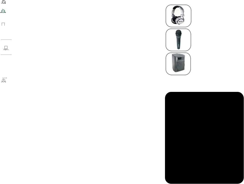
OPTIONAL ACCESSORIES:
DJX-05 Professional DJ Headphones
DJX -05
DJM-2 |
DJM-2 Handheld DJ Microphone |
|
GX-1 |
GX-1 Personal Monitor Speakers |
|
|
For more accessories, visit us at www.geminidj.com.
NOTES:
____________________________________________________
____________________________________________________
____________________________________________________
____________________________________________________
____________________________________________________
____________________________________________________
____________________________________________________
____________________________________________________
____________________________________________________
____________________________________________________
____________________________________________________
____________________________________________________
____________________________________________________
____________________________________________________
____________________________________________________
____________________________________________________
____________________________________________________
____________________________________________________
<7>

A C H T U N G ! BITTE UNBEDINGT VOR BENUTZUNG DES GERÄTS LESEN! WICHTIGE HINWEISE UND SICHERHEITSANWEISUNGEN GEFAHR EINES ELEKTRISCHEN SCHLAGS. GERÄT NICHT ÖFFNEN!
VORSICHT: Dieses Produkt erfüllt die FCC-Regeln, wenn Sie zum Anschluss abgeschirmte Kabel und Stecker verwenden, um es mit anderen Geräten zu verbinden. Auch um elektromagnetische Störungen anderer elektrischer Geräte wie Radios oder Fernseher zu vermeiden, benutzen Sie abgeschirmte Kabel und Stecker für die Verbindungen.
Das Ausrufezeichen im gleichseitigen Dreieck weißt Sie in der Bedienungsanleitung auf wichtige Bedienungsanweisungen und Wartungs- /Serviceanweisungen hin.
Das Blitzsymbol im gleichseitigen Dreieck dient dazu, den Benutzer vor gefährlichen Spannungen an nicht isolierten Stellen im Gehäuse zu warnen, die so groß sind, dass Sie eine Gefahr für den Benutzer darstellen.
ANWEISUNGEN LESEN: Lesen Sie alle Sicherheitsund Bedienungsanweisungen, bevor Sie mit dem Produkt arbeiten. AUFBEWAHRUNGSHINWEIS: Bewahren Sie alle Sicherheitsund Bedienungsanweisungen gut auf.
WARNHINWEISE: Alle Warnhinweise für das Produkt und die Bedienungsanweisungen müssen genau eingehalten werden. ANWEISUNGEN BEFOLGEN: Alle Anweisungen zum Betrieb des Produkts sollten befolgt werden.
REINIGUNG: Das Produkt sollte nur mit einem Polieroder einem weichen trockenen Tuch gereinigt werden. Benutzen Sie dazu niemals Möbelwachs, Benzine, Insektenmittel oder andere flüchtige Reinigungsmittel, denn Sie könnten zur Korrosion des Gehäuses führen.
ERWEITERUNGEN: Benutzen Sie keine Erweiterungen, die nicht vom Hersteller empfohlen sind, da sie zu Risiken führen könnten. WASSER&FEUCHTIGKEIT: Benutzen Sie dieses Produkt nicht in der Nähe von Wasser, z. B. in der Nähe einer Badewanne, einer Waschschüssel, eines Küchenspülbeckens eines Waschbeckens, in einem feuchten Keller, einem Schwimmbecken oder an ähnlichen Orten.
ZUBEHÖR: Stellen Sie das Produkt nicht auf eine wackelige und labile Unterlage. Das Produkt könnte herunterfallen und dabei Kinder oder Erwachsene verletzen, wie auch selber beschädigt werden. Stellen Sie das Produkt nur auf vom Hersteller empfohlene oder verkaufte Unterlagen. Jede Befestigung und Montage des Produkts sollte nach den Anweisungen des Herstellers ausgeführt werden. Nutzen Sie dazu ein vom Hersteller
empfohlenes Montageset.
MOBILE UNTERLAGEN: Bewegen Sie eine Kombination aus dem Produkt und einer mobilen Unterlage mit Vorsicht. Schnelles Anhalten, zu viel Schub oder unebene Böden können dazu führen, dass sich Produkt und mobile Unterlage überschlagen (SIEHE BILD A).
BELÜFTUNG: Schlitze und Öffnungen im Gehäuse sind für die Belüftung vorgesehen. Sie stellen den zuverlässigen Betrieb des Produkts sicher und schützen es vor Überhitzung. Diese Öffnungen dürfen nicht verschlossen, blockiert oder bedeckt werden. Stellen Sie deswegen das Produkt niemals auf ein Bett, ein Sofa, einen Teppich oder Stellen mit ähnlicher Oberfläche. Wenn Sie dieses Produkt in einer festen Installation wie z. B. in einem Regal oder einem Rack einbauen, sorgen Sie für ausreichende Belüftung oder sorgen Sie dafür, dass die Bestimmungen des Herstellers genau eingehalten werden.
STROMANSCHLUSS: Dieses Produkt darf nur mit dem auf dem Gerät angegebenen Strom betrieben werden. Wenn Sie sich nicht sicher sind, welche Stromart Sie bei sich zuhause haben, fragen Sie den Verkäufer des Geräts oder Ihren Stromversorger.
AUFSTELLUNGSORT: Stellen Sie das Gerät an einem festen Ort auf. ZEITEN DES NICHTGEBRAUCHS: Ziehen Sie das Stromkabel aus dem Gerät heraus, wenn Sie es für eine längere Zeit nicht gebrauchen.
ERDUNG ODER POLUNG:
-Wenn dieses Produkt mit einem gepolten Wechselstromstecker (Ein Stecker mit einem Kontakt mehr als andere Stecker) ausgestattet ist, passt dieser nur in einer bestimmten Richtung in die Steckdose und ist ein besonderes Sicherheitsmerkmal. Sollten Sie den Stecker nicht komplett in die Steckdose stecken können, versuchen Sie ihn andersherum einzustecken. Sollte der Stecker auch dann noch nicht in die Steckdose passen, beauftragen Sie einen Elektriker, um diese veraltete Steckdose auszutauschen.
-Wenn dieses Produkt mit einem geerdeten dreipoligen Stecker ausgestattet ist, hat der Stecker einen dritten (Erdungs-)Kontakt und passt nur in eine Steckdose mit entsprechender Erdung. Auch das ist ein Sicherheitsmerkmal. Sollte der Stecker nicht in die Steckdose passen, beauftragen Sie einen Elektriker, um diese veraltete Steckdose auszutauschen.
SCHUTZ DES STROMKABELS: Stromkabel sollten so verlegt werden, dass man nicht auf sie treten kann noch dass sie von darauf stehenden oder gegen sie stoßenden Gegenständen gequetscht werden. Achten Sie besonders auf Kanten, Sicherung, Stecker und Buchsen.
AUSSENANTENNENERDUNG: Wenn Sie eine Außenantenne oder ein Radio-/Fernsehkabelsignal an das Produkt anschließen, achten Sie darauf, dass die Antenne oder das Kabel geerdet sind, um dafür zu sorgen, dass Überspannungen und elektrostatische Aufladungen nicht auftreten können. Im Artikel 810 des National Electrical Code, ANSI/NFPA 70, finden Sie Informationen über die richtige Erdung des Antennenmasts und weitere Informationen zu diesem Thema. (SIEHE AUCH ABBILDUNG B).
GEWITTER: Trennen Sie das Produkt während eines Gewitters oder wenn es unbeaufsichtigt ist oder wenn es für eine lange Zeit nicht benutzt wird durch Ziehen des Stromkabels vom Stromnetz. Trennen Sie auch die Verbindung zu einer Antenne oder Radio-/Fernsehkabeln. Dadurch vermeiden Sie Beschädigungen des Produkts durch Blitze oder Überspannungen.
STROMUND ÜBERLANDLEITUNGEN: Stellen Sie eine Außenantenne nicht in der Nähe von Überlandleitungen, elektrischen Lichtoder Stromkreisen oder an Stellen, wo sie in eine solche Leitung fallen könnte auf. Wenn Sie eine Außenantenne aufstellen, achten Sie besonders darauf,
<8>
dass Sie auf keinen Fall irgendwelche Stromleitungen berührt. Das kann zu gefährlichen Auswirkungen führen.
ÜBERLASTUNG: Überlasten Sie keine Steckdosen, Verlängerungskabel oder Sicherungen. Das kann zu Bränden oder elektrischen Schlägen führen.
EINDRINGEN VON GEGENSTÄNDEN ODER FLÜSSIGKEIT: Führen Sie niemals irgendwelche Gegenstände durch Öffnungen in das Produkt ein. Sie könnten mit Strom führenden Stellen in Verbindung kommen oder Kurzschlüsse verursachen, die zu Bränden oder elektrischen Schlägen führen können. Gießen Sie niemals irgendwelche Flüssigkeiten auf oder in das Produkt.
SERVICE: Versuchen Sie nicht, das Produkt selber zu reparieren. Durch das Öffnen des Gehäuses oder Entfernen von Schrauben können Sie mit gefährlichen Spannungen oder anderen Risiken in Kontakt kommen. Beauftragen Sie im Reparaturfall nur qualifiziertes Servicepersonal.
WANN SERVICE NÖTIG IST: Unter den folgenden Bedingungen ziehen Sie auf jeden Fall das Stromkabel aus der Steckdose und beauftragen Sie für eine Reparatur nur qualifiziertes Servicepersonal:
-Wenn das Stromkabel defekt ist.
-Wenn Flüssigkeit auf oder in das Produkt gelaufen ist oder Gegenstände in das Produkt gefallen sind.
-Wenn das Produkt Regen oder Wasser ausgesetzt war.
-Wenn das Produkt trotz Befolgen der Bedienungsanweisungen nicht normal arbeitet. Stellen Sie dabei das Produkt nur nach den Anweisungen der Bedienungsanleitung ein, andere Einstellungen können das Produkt beschädigen und den aufwändigen Einsatz von Technikern für die Wiederherstellung erfordern.
-Wenn das Produkt hingefallen oder auf andere Art und Weise beschädigt ist.
-Wenn das Produkt eine eindeutige Veränderung im Betrieb zeigt. ERSATZTEILE: Wenn Ihr Produkt Ersatzteile benötigt, achten Sie darauf, dass der Servicetechniker nur vom Hersteller erlaubte Ersatzteile oder Ersatzteile, die die gleichen Eigenschaften wie die originalen Teile aufweisen, einsetzt. Falsche Ersatzteile können zu Bränden, elektrischen Schlägen oder anderen Risiken führen.
SICHERHEITSTEST: Bevor der Service oder eine Reparatur für dieses Produkt beendet sind, beauftragen Sie den Servicetechniker, einen Servicetest durchzuführen, um sicher zu stellen, dass das Produkt einwandfrei funktioniert.
WANDODER DECKENMONTAGE: Das Produkt sollte nicht an einer Wand oder der Decke montiert werden.
HITZE: Stellen Sie das Produkt nicht in die Nähe von Wärmequellen wie Radiatoren, Wärmespeichern, Öfen oder anderen Produkten (auch Verstärker), die Hitze erzeugen.
VERWERTEN SIE WIEDER: Dieses Produkt sollte nicht als Haushaltsmüll entsorgt werden. Entsorgen Sie das Produkt im Bedarfsfall bei einer zuständigen Entsorgungsstelle, die das Recycling der elektrischen und elektronischen Bauteile übernimmt. Wenn Sie das Produkt dem gemäß entsorgen, schützen Sie die Umwelt und die menschliche Gesundheit. Bei nicht sachgemäßer Entsorgung gefährden Sie die Umwelt und die menschliche Gesundheit. Das Recycling verschiedener Materialien hilft, die Natur und Ihre Ressourcen zu schonen. Für nähere Informationen bezüglich der Entsorgung dieses Produkts nehmen Sie Kontakt auf mit Ihrer lokalen Stadtverwaltung, dem zuständigen Entsorgungsunternehmen oder dem Händler, bei dem Sie das Produkt gekauft haben.
 Loading...