

Page 1

Galaxy Power System 4848/100
with Dual Rectifier Shelf
and 595LT Rectifiers S2:0 and later
(GPS 4848/100)
H569-434
Notes: Refer to the Millennium II Product Manual 167-792-181 for Galaxy
Millennium II installation and setup.
Instructions in this manual reference installation and setup of the
Galaxy Millennium Controller.
Refer to User’s Guide Issue 3 for 595LT Series Rectifiers prior to S2:0.
User’s Guide
Select Code 167-792-166
Comcode 108994042
Issue 5 September 2011
Page 2

Page 3

User’s Guide
Select Code 167-792-166
Comcode 108994042
Issue 5
September 2011
Galaxy Power System 4848/
100 with Dual Rectifier Shelf
and 595LT Rectifiers S2:0 and later
(GPS 4848/100)
Notice:
The information, specifications, and procedures in this manual are
subject to change without notice. Lineage Power assumes no
responsibility for any errors that may appear in this document.
Note: Instructions in this manual reference installation and setup of the Galaxy
Millennium Controller. For Galaxy Millennium II installation and setup,
refer to the Millennium II Product Manual 167-792-181.
Refer to User’s Guide Issue 3 for 595LT Series Rectifiers prior to S2:0.
© 2011 Lineage Power
All International Rights Reserved
Printed in U.S.A.
H569-434
Page 4

Page 5

Galaxy Power System 4848/100 with Dual Rectifier Shelf
Table of Contents
1 Introduction
GPS 4848/100 1-1
Overview 1-1
Related Documentation 1-1
Illustration 1-2
Safety 1-3
Electromagnetic Compliance 1-3
CE Marking 1-3
Telcordia 1-3
Customer Service Contacts 1-4
Customer Service, Technical Support, Product Repair and
Return, and Warranty Service 1-4
Customer Training 1-4
Downloads and Software 1-4
2 System Description
Overview 2-1
Block Diagram 2-1
System Components 2-2
Bonding Network 2-2
Facility 2-2
Architecture 2-3
Introduction 2-3
Distributed 2-3
Centralized 2-5
Standard 2-7
Non-Traditional 2-7
3 Galaxy Millennium Controller
Overview 3-1
Mounting Location 3-1
Circuit Boards 3-1
Reference Material 3-1
Controller Product Manual 3-1
RPM System Product Manual 3-1
User Interface and Display 3-2
Front Panel 3-2
Default Display 3-2
LEDs 3-3
Issue 5 September 2011 Table of Contents - 1
Page 6

Galaxy Power System 4848/100 with Dual Rectifier Shelf
Pushbutton Controls 3-3
Test Jacks 3-4
4 Rectifiers
595 Series 4-1
Overview 4-1
Front Panel Display 4-2
Power Switch 4-2
Status Indicators 4-2
Current Display 4-2
Lamp Test 4-2
Illustration 4-2
Features 4-3
Output Voltage Adjustment 4-3
Output Current “Walk-in” 4-3
Electronic Current Limit 4-3
Selective High Voltage Shutdown (SHVSD) 4-3
Backup High Voltage Shutdown (BHVSD) 4-3
Restart 4-3
Output Circuit Breaker 4-3
Fan Alarm and Control 4-3
Thermal Alarm 4-4
Controller Communications Alarm 4-4
Autonomous Operation of the Rectifier 4-4
Connectorized 4-4
“Forced” Load Sharing 4-4
5 AC Input Panels
Overview 5-1
AC Service 5-1
Illustrations 5-1
6 Battery Connection Panels
Overview 6-1
Introduction 6-1
Distributed Architecture 6-1
Centralized Architecture 6-1
Illustrations 6-1
7 DC Distribution Panels
Overview 7-1
2 - Table of Contents Issue 5 September 2011
Page 7

Galaxy Power System 4848/100 with Dual Rectifier Shelf
Function 7-1
Illustrations 7-1
8 Circuit Boards
Overview 8-1
Function 8-1
Terminal Boards 8-1
Alarm Boards 8-1
Alarm/Terminal Boards 8-1
BLJ Terminal Board 8-1
Bay Interface Card 8-2
Contactor Control Board 8-2
9 Specifications
GPS 4848/100 9-1
Rectifiers 9-4
AC Input Panels 9-6
Battery Connection Panels 9-7
DC Distribution Panels 9-8
10 Safety
11 Maintenance and Replacement
Requirements 11-1
System 11-1
Batteries 11-1
Controller 11-1
Rectifier 11-2
Vacant Rectifier Positions 11-2
Rectifier Fan Assembly 11-2
Replacement Procedures 11-3
Installing or Replacing a Rectifier 11-3
Removing a Rectifier 11-6
Replacing the Rectifier Fan Assemblies 11-7
Testing 11-9
Testing Additional Alarms After Replacing Rectifiers 11-9
Testing Rectifiers and Load Share in Bay Expansions 11-9
Replacement Parts 11-10
System 11-10
Millennium Controller Circuit Boards 11-11
Additional Ordering Information 11-11
Issue 5 September 2011 Table of Contents - 3
Page 8

Galaxy Power System 4848/100 with Dual Rectifier Shelf
Documentation 11-11
Software 11-11
12 Troubleshooting Preparations
Preliminary 12-1
Introduction 12-1
Safety 12-1
Tools 12-1
Troubleshooting Procedure 12-2
Purpose 12-2
Cabinet Alarm 12-2
System Status 12-3
Alarms Menu 12-3
Troubleshooting Tables 12-3
Identifying Problems 12-3
Reference Figures 12-4
Figure Numbers and Titles 12-4
Millennium Controller 12-4
Rectifier 12-6
Low Voltage Battery Disconnect 12-7
AC Input 12-8
AC Input 12-9
DC Distribution 12-10
Low Voltage Load Disconnect 12-11
13 Troubleshooting Millennium Systems
Introduction 13-1
In This Section 13-1
Preparation 13-1
Technical Assistance 13-1
Troubleshooting Tables 13-2
Organization 13-2
Table Reference 13-2
Rectifier Display Messages and LEDs 13-2
Millennium Controller Display 13-3
AC Alarm LED 13-3
BATT Alarm LED 13-4
CTRL Alarm LED 13-5
DIST Alarm LED 13-9
RECT Alarm LED 13-10
BD and RM Alarm LEDs, or No LED 13-15
4 - Table of Contents Issue 5 September 2011
Page 9

Galaxy Power System 4848/100 with Dual Rectifier Shelf
14 Product Warranty
Revision History
Issue 5 September 2011 Table of Contents - 5
Page 10

Galaxy Power System 4848/100 with Dual Rectifier Shelf
6 - Table of Contents Issue 5 September 2011
Page 11

Galaxy Power System 4848/100 with Dual Rectifier Shelf
List of Figures
Figure 1-1: GPS 4848/100 With Millennium Controller 1-2
Figure 2-1: Block Diagram of the GPS 4848/100
(Distributed Architecture) 2-1
Figure 2-2: Distributed Architecture 2-4
Figure 2-3: Distributed Architecture Initial and Growth Cabinets
2-4
Figure 2-4: Centralized Architecture 2-5
Figure 2-5: Centralized Architecture Cabinets 2-6
Figure 2-6: Non-Traditional Cabling Arrangements 2-7
Figure 3-1: Galaxy Millennium Controller Front Panel 3-2
Figure 4-1: Rectifier Front Panel 4-2
Figure 5-1: H569-434 G20/320/420 (ED83142-30 G3)
208/240V AC Input Circuit Breaker Panel - 4 Rectifier 5-2
Figure 5-2: H569-434 G21/23/321/323/421 (ED83142-30 G4)
208/240/480V AC Input Circuit Breaker Panel - 6 Rectifier 5-2
Figure 5-3: H569-434 G334/335 (ED83142-30 G24/25)
208/240/480V AC Input Circuit Breaker Panel - 12 Rectifier 5-3
Figure 5-4: H569-434 G22/322 (ED83142-30 G2)
480V AC Input Circuit Breaker Panel - 4 Rectifier 5-3
Figure 5-5: H569-434 G24/25/26/27/324/325/326/327/330/331
(ED83142-30 G5)
208/240/480V AC Input Terminal Strip Panel - 6 Rectifier 5-4
Figure 5-6: H569-434 G128/129/130/131 (ED83142-30 G18)
208/240/480V AC Input Terminal Strip Panel - 8 Rectifier 5-4
Figure 5-7: H569-434 G328/329/332/333 (ED83142-30 G26)
208/240/480V AC Input Terminal Strip Panel - 14 Rectifier 5-5
Figure 5-8: H569-434 G70/370/470 (ED83142-30 G10)
480V 65kAIC AC Input Circuit Breaker Panel - 4 Rectifier 5-5
Issue 5 September 2011 List of Figures - 1
Page 12

Galaxy Power System 4848/100 with Dual Rectifier Shelf
Figure 5-9: H569-434 G71/371/471 (ED83142-30 G11)
480V 65kAIC AC Input Circuit Breaker Panel - 6 Rectifier 5-6
Figure 6-1: H569-434 G30 (ED83143-31 G32)
Battery Connection Panel 6-2
Figure 6-2: H569-434 G31 (ED83143-31 G31)
Battery Connection Panel 6-2
Figure 6-3: H569-434 G32/32A (ED83143-31 G30/30A)
Battery Connection Panel 6-3
Figure 6-4: H569-434 G34 (ED83143-31 G41)
Battery Connection Panel 6-3
Figure 6-5: H569-434 G35 (ED83143-31 G42)
Battery Connection Panel 6-4
Figure 6-6: H569-434 G37/38 (ED83143-31 G60/61)
Battery (OLE) Connection Panel 6-4
Figure 6-7: H569-434 G80/81/82 (ED83143-31 G31/43)
Battery Connection Panel 6-5
Figure 6-8: H569-434 G86/87 (ED83143-31 G63/64)
Battery Connection Panel 6-6
Figure 6-9: H569-434 G39 (ED83143-31 G36)
Battery Connection Panel 6-6
Figure 7-1: H569-434 G40/45/50/55 (ED83143-31 G11)
400A DC Distribution Panel 7-2
Figure 7-2: H569-434 G41/46/51/56 (ED83143-31 G12)
400A DC Distribution Panel 7-2
Figure 7-3: H569-434 G42/47 (ED83143-31 G2)
600A DC Distribution Panel 7-3
Figure 7-4: H569-434 G43 (ED83143-31 G1)
1200A DC Distribution Panel 7-3
Figure 7-5: H569-434 G48 (ED83143-31 G5)
1000A DC Distribution Panel 7-4
Figure 7-6: H569-434 G52 (ED83143-31 G53)
600A DC Distribution Panel 7-4
Figure 7-7: H569-434 G53/57 (ED83143-31 G55)
1000A DC Distribution Panel 7-5
2 - List of Figures Issue 5 September 2011
Page 13

Galaxy Power System 4848/100 with Dual Rectifier Shelf
Figure 7-8: H569-434 G60/61/65/66 (ED83143-31 G71)
600A DC Distribution Panel 7-5
Figure 7-9: H569-434 G67 (ED83143-31 G22)
600A DC Distribution Panel 7-6
Figure 7-10: H569-434 G68 (ED83143-31 G21)
1200A DC Distribution Panel 7-6
Figure 7-11: H569-434 G96 (ED83143-31 G15)
510A DC Distribution Panel 7-7
Figure 7-12: H569-434 G97 (ED83143-31 G16) 14-Position, and
H569-434 G98 (ED83143-31 G17) 22-Position DC Distribution
Panel 7-7
Figure 7-13: H569-434 G54 (ED83143-31 G54) 5-Position DC Dis-
tribution Panel 7-8
Figure 7-14: H569-434 G58 (ED83143-31 G58) 6-Position GMT DC
Distribution Panel 7-8
Figure 7-15: H569-434 G59 (ED83143-31 G56) 2-Position Fuse Dis-
tribution Panel 7-9
Figure 11-1: Installing a Rectifier in a Rectifier Shelf 11-4
Figure 11-2: Rectifier Fan Replacement 11-7
Figure 12-1: Location of Cabinet Alarm Light and Controller 12-2
Figure 12-2: Millennium Controller Display 12-5
Figure 12-3: Millennium Controller Fuses and Circuit Boards 12-5
Figure 12-4: Rectifier Display 12-6
Figure 12-5: Low Voltage Battery Disconnect
Contactor Control Switches 12-7
Figure 12-6: AC Input Panel and Rectifier Positions, 6 Rectifiers
12-8
Figure 12-7: AC Input Panel and Rectifier Positions, 12 Rectifiers
12-9
Figure 12-8: DC Distribution Panel 12-10
Figure 12-9: Low Voltage Load Disconnect Contactor
Control Switches 12-11
Issue 5 September 2011 List of Figures - 3
Page 14

Galaxy Power System 4848/100 with Dual Rectifier Shelf
4 - List of Figures Issue 5 September 2011
Page 15

Galaxy Power System 4848/100 with Dual Rectifier Shelf
List of Tables
Table 9-A: Galaxy Power System 4848/100 Specifications 9-1
Table 9-B: 595LT Series S2:x Rectifier Specifications 9-4
Table 9-C: Rectifier Display Messages and LEDs 9-5
Table 9-D: AC Panels 9-6
Table 9-E: Battery Connection Panels 9-7
Table 9-F: DC Distribution Panels 9-8
Table 11-A: GPS 4848/100 Replacement Parts 11-10
Table 11-B: Galaxy Millennium Controller Circuit Boards 11-11
Table 11-C: Product Documentation 11-11
Table 13-A: AC Alarms 13-3
Table 13-B: Battery Alarms 13-4
Table 13-C: Controller Alarms 13-5
Table 13-D: Distribution Alarms 13-9
Table 13-E: Rectifier Related Alarms 13-10
Table 13-F: Miscellaneous Alarms 13-15
Issue 5 September 2011 List of Tables - 1
Page 16

Page 17

Galaxy Power System 4848/100 with Dual Rectifier Shelf
1 Introduction
GPS 4848/100
Overview The Galaxy Power System (GPS) 4848/100 provides -48 volt
telecommunications powering solutions in worldwide markets. The
GPS 4848/100 combines 220 and 200-ampere, fan-cooled, switchmode
rectifiers, microprocessor control technologies, battery and load
disconnect/reconnect options, and a comprehensive line of fuse and
circuit breaker dc distribution options in a modular front-access design.
This modularity ensures easy access, simplified installation and
maintenance, and allows the system to expand in capacity and features
as power needs grow.
With 14,080-ampere maximum capacity, distribution flexibility, and
universal ac input capability, the GPS 4848/100 supports switching,
transmission, and wireless applications in central office locations and
environmentally controlled remote sites (huts or vaults). For centralized
architecture, bus bars are available to 14,080A.
Notes This document includes information for 595LT series S2:0 and later
rectifiers. Refer to User’s Guide Issue 3 for 595LT Series Rectifiers
ior to S2:0. For information about 595A and 595B series rectifiers see
pr
the GPS 4848/100 User’s Guide.
595A and 595B series rectifiers (full width, one per shelf) are fully
supported by GPS 4848/100 with Dual Rectifier Shelves.
Related Documentation
Ordering Guide H569-434
Manufacturing Drawings ED83142-30 (AC)
Wiring Diagram T83314-30
User’s Guide 167-792-155
GPS4848/100
ED83143-31 (DC)
J85582C-1 (System)
Issue 5 September 2011 Introduction 1 - 1
Page 18
Galaxy Power System 4848/100 with Dual Rectifier Shelf
Galaxy
Millennium
Controller
BLJ3
Terminal
Board
Battery Connection Panel
AC Panel
595LT Series
220A Rectifiers
DC Distribution
GPS 4848/100, continued
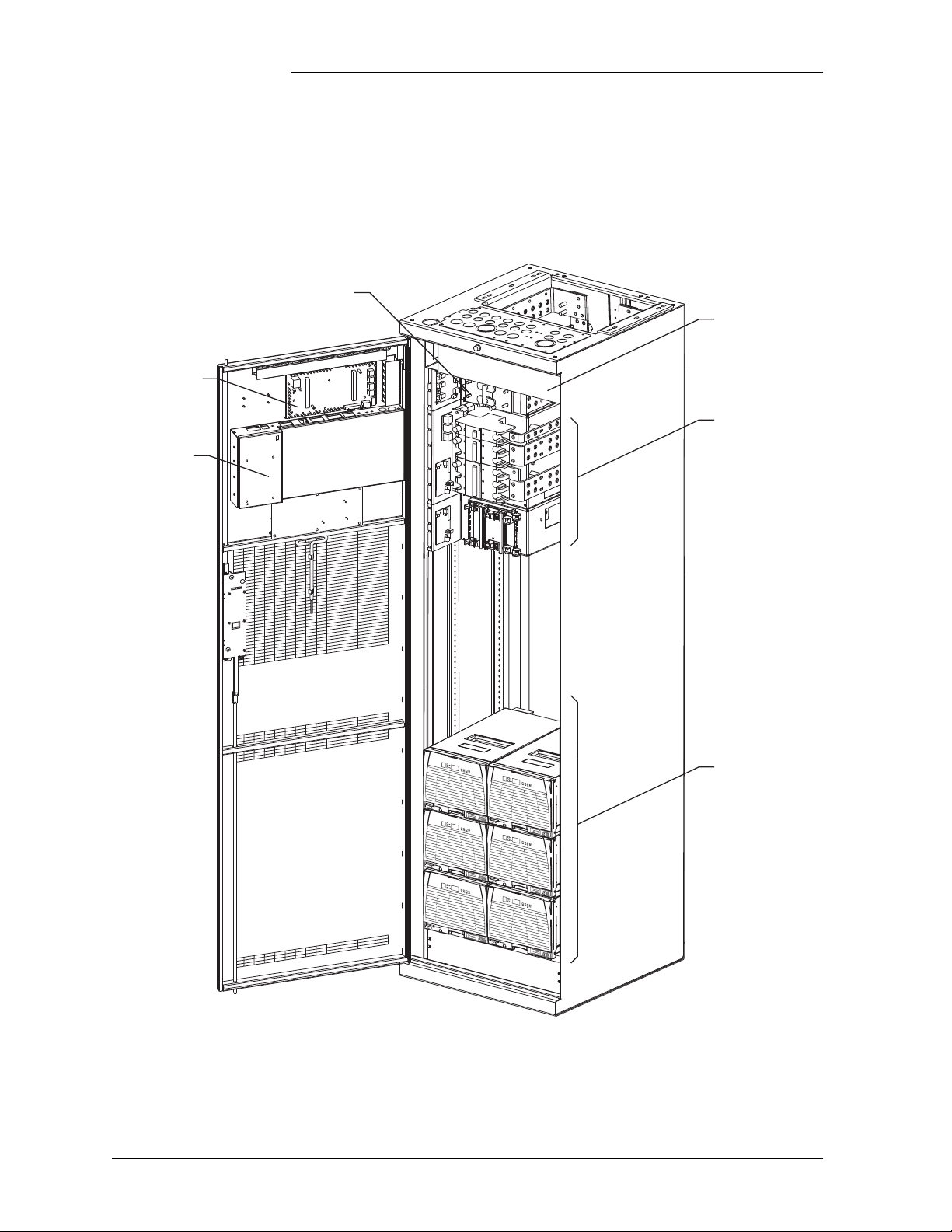
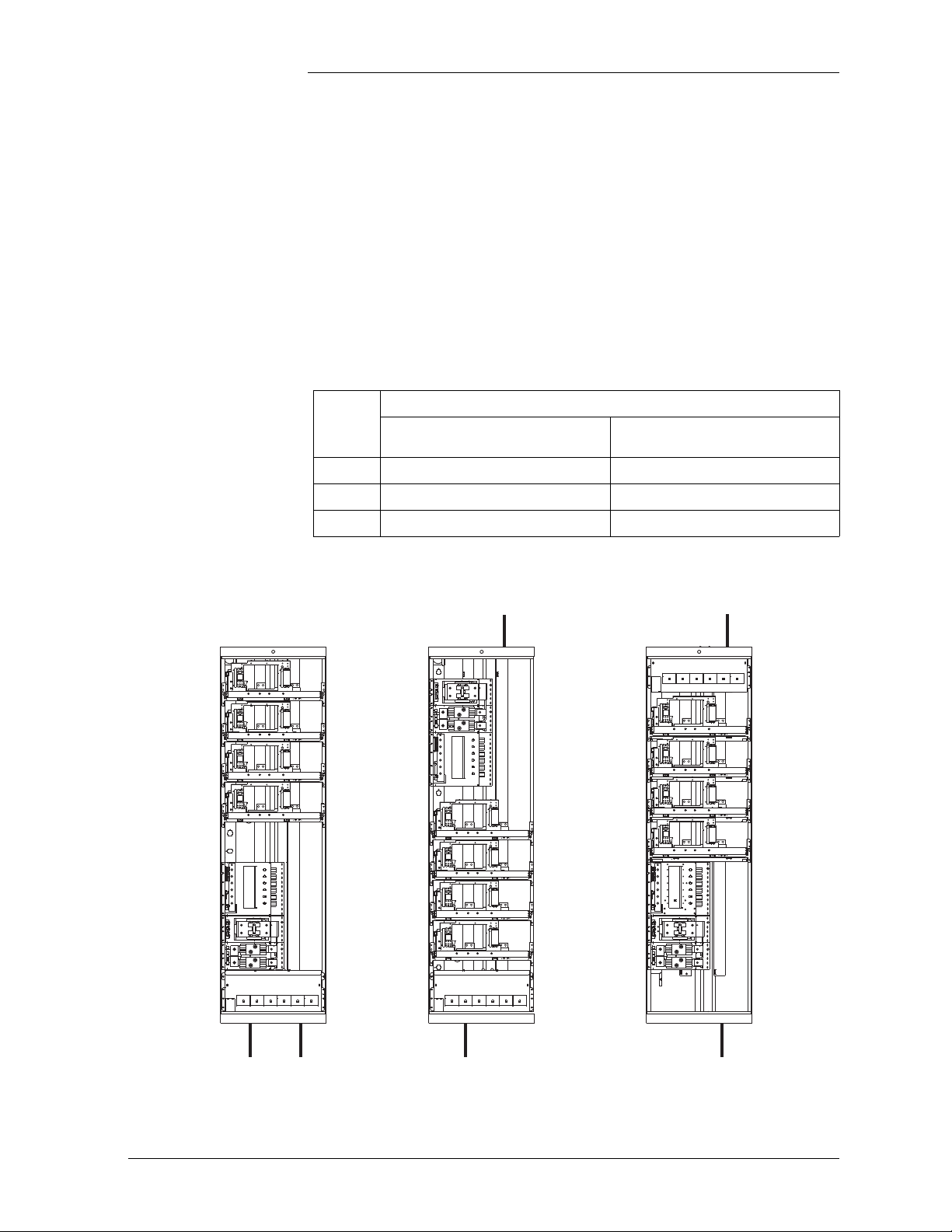
Illustration Figure 1-1 is an isometric view of the GPS 4848/100 with a Millennium
Controller.
Figure 1-1: GPS 4848/100 With Millennium Controller
1 - 2 Introduction Issue 5 September 2011
Page 19

Galaxy Power System 4848/100 with Dual Rectifier Shelf
GPS 4848/100, continued
Safety •UL1 Listed (US and Canada): UL Subject 1801 with applicable
sections of UL1950/CSA2 950)
• VDE Licensed to VDE 0805/IEC950/EN60950
Electromagnetic
• Emission:
Compliance
– FCC Part 15 Class B
– EN55022 (CISPR 22) Radiated/Conducted Emission, Class B
• Immunity
– IEC/EN 61000-4-2 ESD level 3 and 4
– IEC/EN 61000-4-3 Radiated Immunity, 10V/m
– IEC/EN 61000-4-4 Electrical Fast transients/Burst, level 4
– IEC/EN 61000-4-5 Lightning Surge, level 4
CE Marking • CE marked per European Union Council Directives:
– Low-Voltage Directive (73/23/EEC) and
– EMC Directive (89/336/EEC) as amended by CE Marking
Directive (93/68/EEC)
Telcordia • GR-63 and GR-1089 NEBS (including Level 3 testing)
• Report by an independent test laboratory - NRTL
1.UL is a registered trademark of Underwriters Laboratories, Inc.
2.CSA is a registered trademark of Canadian Standards Association.
Issue 5 September 2011 Introduction 1 - 3
Page 20

Galaxy Power System 4848/100 with Dual Rectifier Shelf
Customer Service Contacts
Customer Service, Technical Support, Product Repair and Return, and Warranty Service
For customers in the United States, Canada, Puerto Rico, and the US
Virgin Islands, call 1-800-THE-1PWR (1-800-843-1797). This number
is staffed from 7:00 am to 5:00 pm Central Time (zone 6), Monday
through Friday, on normal business days. At other times this number is
still available, but for emergencies only. Services provided through this
contact include initiating the spare parts procurement process, ordering
documents, product warranty administration, and providing other
product and service information.
For other customers worldwide the 800 number may be accessed after
first dialing the AT&T Direct country code for the country where the
call is originating, or you may contact your local field support center or
your sales representative to discuss your specific needs.
Customer Training Lineage Power offers customer training on many Power Systems
products. For information call 1-972-284-2163. This number is
answered from 8:00 a.m. until 4:30 p.m., Central Time Zone (Zone 6),
Monday through Friday.
Downloads and Software
To download the latest product information, product software and
software upgrades, visit our web site at
http://www.lineagepower.com
1 - 4 Introduction Issue 5 September 2011
Page 21

Galaxy Power System 4848/100 with Dual Rectifier Shelf
LVLD
DISCHG RTN
LVLD
Control
Board
Rectifiers
DC Distribution
Controller
Return
Bus
(+)
To 48 Volt
Loads
AC Input
Power
48V
Returns
LVBD
BAT BUS
CHG RTN
LVBD
Control
Board
Battery Distribution
Battery (-)
Battery
Shunt
Battery (+)
CO
GND
Sense/Control
Connections
AC Input
Chg
Bus
(-)
2 System Description
Overview
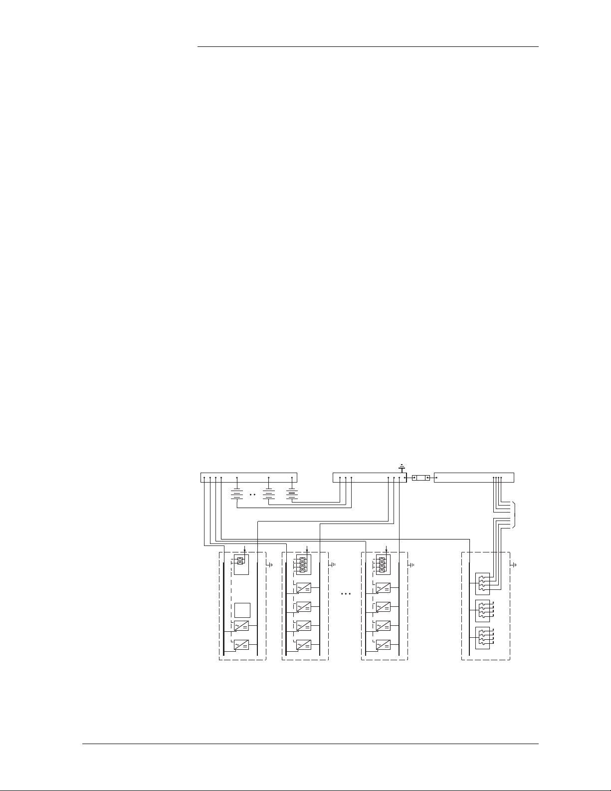
Block Diagram Figure 2-1 shows a basic block diagram of the Galaxy Power System
4848/100. It illustrates the arrangement and interconnections of the
system components from the ac input to the dc output.
Figure 2-1: Block Diagram of the GPS 4848/100
(Distributed Architecture)
Issue 5 September 2011 System Description 2 - 1
Page 22

Galaxy Power System 4848/100 with Dual Rectifier Shelf
Overview, continued
System Components
The power system accepts alternating current from the commercial
utility or a standby ac power source and rectifies it to produce dc power
for the using equipment. The system’s control and alarm functions
interact with the rectifiers and the office. In addition, the system
provides overcurrent protection and charge, discharge, and distribution
facilities. Battery reserve automatically provides a source of dc power if
the commercial or standby ac fails. Battery reserve can be engineered to
supply dc power for a specific period of time. In normal practice, battery
capacity is sized to provide 3 to 8 hours of reserve time.
AC Input connects the commercial and/or standby ac power sources to
the rectifiers within the system and provides overcurrent protection. In
some applications the ac service is wired directly to the rectifiers and
overcurrent protection is provided at the service panel.
Rectifiers convert an ac source voltage into the dc voltage level required
to charge and float the batteries and to power the using equipment.
Controller provides the local and remote control, monitoring, and
diagnostic functions required to administer the power system.
Batteries provide energy storage for an uninterrupted power feed to the
using equipment during loss of ac input or rectifier failure.
DC Distribution Panel provides overcurrent protection, connection
points for the using equipment, and bus bars used to interconnect the
rectifiers, batteries, and dc distribution.
Battery Connection Panel provides connection points for the battery
strings through battery disconnect fuse, contactors, current monitoring
shunts, and equalize converters.
Bonding Network The GPS 4848/100 system is suitable for installation as part of a
Common Bonding Network (CBN) or an Isolated Bonding Network
(IBN).
Facility The GPS 4848/100 system is suitable for installation in Network
Telecommunication Facilities and locations where NEC applies.
2 - 2 System Description Issue 5 September 2011
Page 23

Galaxy Power System 4848/100 with Dual Rectifier Shelf
Architecture
Introduction For the GPS 4848/100 system, the basic system components, i.e., ac
input panels, battery connection panels, dc distribution panels, rectifiers,
and controller, can be configured to form two distinct system
architectures: distributed or centralized.
Distributed In this system each cabinet contains ac distribution, dc distribution
panels, battery connection panels, rectifiers, termination points for load
circuits, and a battery shunt. The initial cabinet also contains the system
controller and, as such, it can function as a stand-alone system. The
rectifier output buses are interconnected to permit cabinets to share
current and ensure common voltage references for all system rectifiers.
Because each cabinet is basically a self-contained system, the overall
system capacity can be increased by simply adding cabinet/battery
entities. However, growing the system requires a distinct, dedicated
floor plan.
During normal operation, the readings from the battery shunts are
summed and subtracted from the rectifier current to obtain the system
load current. While the batteries are providing the system load power,
the individual battery shunts may be monitored to determine the status
of the individual battery sections.
Cabinets can be equipped with load and/or battery disconnect/reconnect
contactors. Battery contactors prevent battery damage during deep
discharges by disconnecting batteries. Load contactors can extend the
time critical loads operate on battery discharge by disconnecting
non-critical loads during discharge.
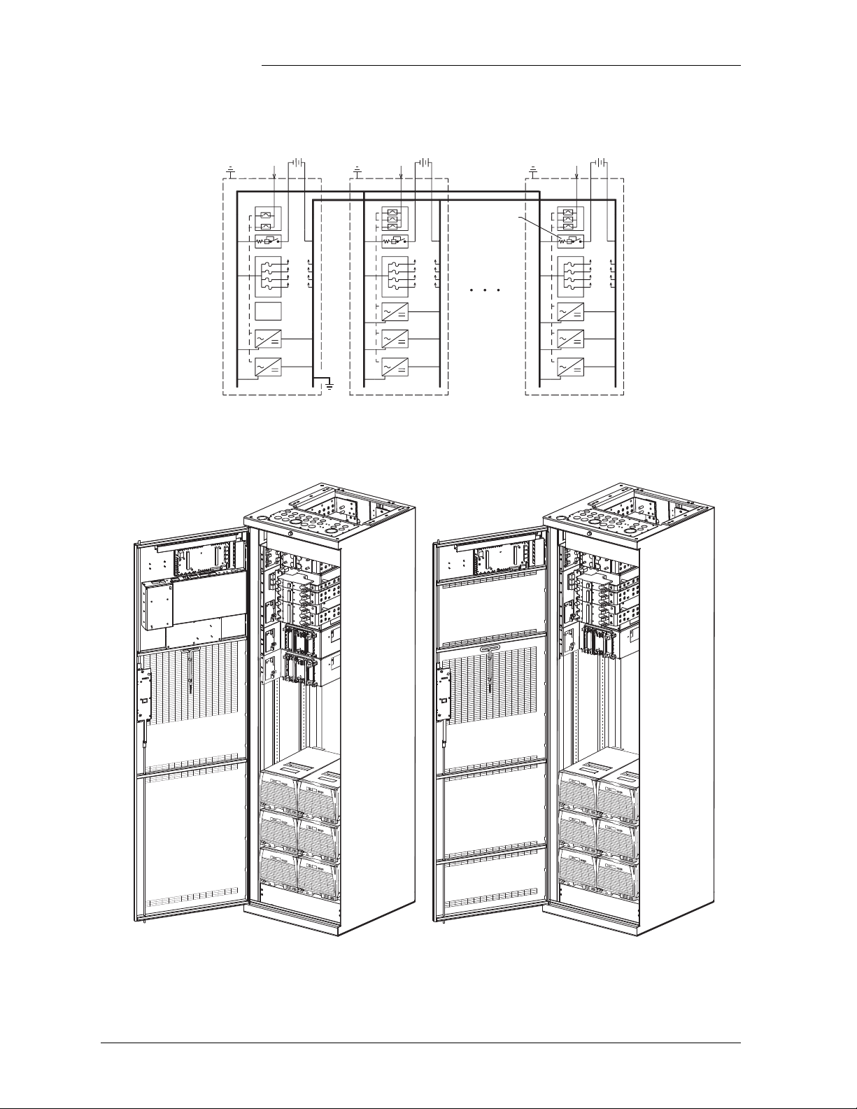
Figure 2-2 shows an example of GPS 4848/100 components configured
in a distributed architecture; Figure 2-3 gives a front view of the
distributed initial and growth cabinets.
Issue 5 September 2011 System Description 2 - 3
Page 24
Control
and
Monitor
Battery Shunt
To Loads
Battery String
Galaxy Power System 4848/100 with Dual Rectifier Shelf
Initial Cabinet
Growth Cabinet
Architecture, continued
Figure 2-2: Distributed Architecture
Figure 2-3: Distributed Architecture Initial and Growth Cabinets
2 - 4 System Description Issue 5 September 2011
Page 25
Galaxy Power System 4848/100 with Dual Rectifier Shelf
Charge Bus Charge Return Bus Discharge Return Bus
Battery Strings
Plant
Shunt
Control
and
Monitor
Loads
Architecture, continued
Centralized Figure 2-4 shows GPS 4848/100 components configured in a
centralized architecture; Figure 2-5 provides a view of the centralized
architecture cabinets with and without controller.
Rectifiers, dc distribution panels, and batteries are cabled to external
busbars where a single system shunt is provided to measure total system
load current.
Rectifier cabinets contain ac distribution or ac terminal blocks,
rectifiers, and cable termination points.
DC distribution cabinets contain load protectors, load cable termination
points, and may include load disconnect/reconnect contactors.
The GPS 4848/100 controller may be provided in a dc distribution
cabinet or a rectifier cabinet equipped with ac circuit breakers. The
cabinet with the controller also contains termination points for the
system interconnect cables.
This architecture requires extensive up-front planning to determine the
ultimate system capacity and engineering to size the external busbars
appropriately; however, the system plan is not constrained to dedicated
layouts as required for distributed architecture systems.
Figure 2-4: Centralized Ar
Issue 5 September 2011 System Description 2 - 5
chitecture
Page 26
Galaxy Power System 4848/100 with Dual Rectifier Shelf
Architecture, continued
Cabinet with Controller
Cabinet without Controller
Figure 2-5: Centralized Architecture Cabinets
2 - 6 System Description Issue 5 September 2011
Page 27
Galaxy Power System 4848/100 with Dual Rectifier Shelf
AC Input
Battery and
DC Load Leads
AC Input
Battery and
DC Load Leads
AC Input
Battery and
DC Load Leads
"A" Arrangement "B" Arrangement "C" Arrangement
REMOVE
BEFORE
ADDING
SECOND
RECTIFIER
REMOVE
BEFORE
ADDING
SECOND
RECTIFIER
REMOVE
BEFORE
ADDING
SECOND
RECTIFIER
REMOVE
BEFORE
ADDING
SECOND
RECTIFIER
REMOVE
BEFORE
ADDING
SECOND
RECTIFIER
REMOVE
BEFORE
ADDING
SECOND
RECTIFIER
REMOVE
BEFORE
ADDING
SECOND
RECTIFIER
REMOVE
BEFORE
ADDING
SECOND
RECTIFIER
REMOVE
BEFORE
ADDING
SECOND
RECTIFIER
REMOVE
BEFORE
ADDING
SECOND
RECTIFIER
REMOVE
BEFORE
ADDING
SECOND
RECTIFIER
REMOVE
BEFORE
ADDING
SECOND
RECTIFIER
Cabinet Cabling Options
Standard Standard cabinets are designed so that ac, battery, and dc load cables are
run through the top of the cabinet.
Non-Traditional Any of the battery panels and dc load panels (shown in Sections 6 and
7) may be used in cabinets that have non-traditional cabling orientations.
However, only G20, G22, G24, G26, and G27 ac panels (shown in
Section 5) are available for these cabinets (see Figure 2-6). Suffixes of
the ac panels indicate the cabling arrangements listed below:
AC
Cabling Arrangement
Panel
Suffix
A
B
C
Note: Check
Through bottom of cabinet Through bottom of cabinet
Through bottom of cabinet Through top of cabinet
Through top of cabinet Through bottom of cabinet
H569-434 for availability.
AC Battery and DC Load
Figure 2-6: Non-Traditional Cabling Arrangements
Issue 5 September 2011 System Description 2 - 7
Page 28

Galaxy Power System 4848/100 with Dual Rectifier Shelf
2 - 8 System Description Issue 5 September 2011
Page 29

Page 30

Galaxy Power System 4848/100 with Dual Rectifier Shelf
2 - 10 System Description Issue 5 September 2011
Page 31

Galaxy Power System 4848/100 with Dual Rectifier Shelf
3 Galaxy Millennium Controller
Overview
Mounting Location The Galaxy Millennium Controller mounts inside the front door with the
display viewed from the outside.
Circuit Boards The Galaxy Millennium Controller is equipped with a Basic control
board for basic operations and an optional Intelligent control board that
provides advanced local and remote monitoring and data acquisition
features. These control boards monitor each other’s status and issue
appropriate alarms in the event a failure occurs. Circuit packs are
accessed by opening the hinged cover from the left side.
Reference Material
Controller Product Manual
RPM System Product Manual
A Galaxy Millennium Controller, Select Code 167-792-180, is
furnished with every GPS 4848/100. Refer to the manual for
information regarding configuration and operation.
Refer to the Galaxy Remote Peripheral Monitoring System product
manual (Select Code 167-790-063) for additional information regarding
module operation.
Issue 5 September 2011 Galaxy Millennium Controller 3 - 1
Page 32
Galaxy Power System 4848/100 with Dual Rectifier Shelf
Galaxy Millennium Controller
Alarm Status
Critical
Escape Help
Enter
Menu
Equipment Status
AC System
Battery
Controller
Distribution
Rectifier
Remote
Modules
Major
Minor
Normal
Battery on
Discharge
V
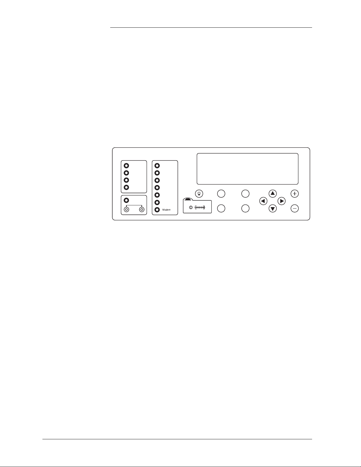
User Interface and Display
Front Panel The control panel displays alarm and status indicators and provides test
jacks to monitor the system output. Keys are provided for interacting
with various menus that configure and monitor the system. The
controller menus can be viewed in either English or Spanish.
The user’s primary interface with the controller is a panel that includes
a backlit LCD front panel display, two rows of LEDs, test jacks, and an
array of simple pushbutton controls. See Figure 3-1.
Default Display The default display shows basic plant status. The controller returns to
3 - 2 Galaxy Millennium Controller Issue 5 September 2011
Figure 3-1: Galaxy Millennium Controller Front Panel
this display three minutes after the last time a key is pressed. The default
screen display is similar to the following: The first line shows the
number of alarms (0) and warnings (0) present in the system, the date
and time. The next two lines show the plant voltage and the plant load.
The last line shows the plant mode, which can be FLOAT, BOOST, STC
(Slope Thermal Compensation), BTP (Battery Thermal Protection, a
boost mode that offers protection against thermal runaway), or BATT
TEST mode.
The information on the screen is updated automatically approximately
every two seconds.
Page 33

Galaxy Power System 4848/100 with Dual Rectifier Shelf
User Interface and Display, continued
LEDs Two columns of LEDs show the severity and source of active alarms.
An alarm event may activate two LEDs: one Alarm Status LED and one
Equipment Status LED. More than one of the Equipment Status LEDs
may be active simultaneously. In that case, the Alarm Status LED that
is active will be that of the most severe active alarm.
The first column has five LEDs. The first four indicate the severity of
the reported alarms: Critical, Major, Minor, and Normal. The fifth LED,
labeled Battery on Discharge, illuminates when the plant voltage is
below the threshold set for this alarm condition in the plant
configuration.
The second column includes seven LEDs, six of which indicate the
source of the alarm: AC System, Battery, Controller, Distribution,
Rectifier, or Remote Module. The final Modem LED will be active
whenever the controller modem port is in use.
Pushbutton Controls
The pushbutton identified with an illuminated lamp icon can be used to
test the controller’s circuit pack and front panel LEDs. It will also test
the indicators of all serially connected devices.
A group of pushbutton keys beneath the backlit LCD display provides
the primary user interface with the controller. These keys are used singly
or in combination to navigate through the controller’s menus. The
following is the general description of these keys.
• Up arrow key: Use to navigate the menu; press the key to move the
cursor up one line.
• Down arrow key: Use to navigate the menu; press the key to move
the cursor down one line.
• Left arrow key: Use to navigate the menu; press the key to move
the cursor left one field.
• Right arrow key: Use to navigate the menu; press the key to move
the cursor right one field.
• MENU key: Press this key any time to view the MAIN menu.
• HELP key: Press this key to display limited on-line help
information.
• ENTER key: Use this key to select a menu item.
• ESCAPE key: Use this key to return to the immediately higher
level menu.
Issue 5 September 2011 Galaxy Millennium Controller 3 - 3
Page 34

Galaxy Power System 4848/100 with Dual Rectifier Shelf
User Interface and Display, continued
Test Jacks A pair of test jacks allows direct measurement of the system voltage
being monitored, normally the battery voltage. This is the same point
regulated as system voltage and displayed on the front panel.
3 - 4 Galaxy Millennium Controller Issue 5 September 2011
Page 35

Galaxy Power System 4848/100 with Dual Rectifier Shelf
4 Rectifiers
595 Series
Overview Four rectifiers are available for the GPS 4848/100 system with dual
rectifier shelves: 595A Series, 595B Series, 595LTA Series, and
595LTB Series.
GPS4848/100 Rectifiers
DC
Series
595A 200A 1 320-530Vac
595B 200A 1 170-260Vac
595LTA 220A 2 320-530Vac
595LTB 220A 2 170-260Vac
The rectifiers are shipped separately from the cabinets for quick and
straightforward installation into rectifier shelves at the site.
Interconnections to ac input, dc output, and control signals occur
automatically during insertion. The rectifiers are keyed to prevent
installation of a rectifier with incompatible ac input. No operational
settings or adjustments to potentiometers are necessary. The installer
must set the ID of each rectifier using its ON/STBY switch to allow the
controller to identify the rectifier for status and alarm reporting.
595A and 595B series rectifiers (full width, one per shelf) are fully
supported. See GPS 4848/100 User's Guide for views and other details
of 595A and 595B series rectifiers.
Current
Rectifiers
per Shelf
3-Phase AC
Input Voltage
Issue 5 September 2011 Rectifiers 4 - 1
Page 36

Galaxy Power System 4848/100 with Dual Rectifier Shelf
ABC12345678
Model: 595LTA
480V 48V
RECTIFIER
KZO41234567 SX:X
DC
220A/48V
ON
STBY
ALM LIM FAN
ALM
BST
Front Panel Display
Power Switch This three-position switch has two functions:
• It controls the on/standby state of the rectifier.
• It is used to set the rectifier ID.
Status Indicators In addition to the ON and STBY LEDs, four other LEDs on the
rectifier’s faceplate indicate the rectifier’s condition.
• The ALM LED is red and lights when a thermal alarm occurs or a
rectifier fail condition occurs. This LED blinks when
communication with the plant controller is not active.
• The LIM LED is yellow lights when the unit is in current limit.
• The FAN AL M LED is red and lights when the fan inside the
rectifier is not functioning properly.
• The EQL LED is yellow and lights when the rectifier is in equalize
mode.
Current Display This display indicates the current of the rectifier. Upon specific
no-power conditions, the 3-digit display will show informative
messages.
Lamp Test To test the LEDs on the rectifier front panel, use the Lamp Test feature
of the controller.
Illustration
Figure 4-1: Rectifier Front Panel
4 - 2 Rectifiers Issue 5 September 2011
Page 37

Features
Galaxy Power System 4848/100 with Dual Rectifier Shelf
Output Voltage Adjustment
Output Current “Walk-in”
Electronic Current Limit
Selective High Voltage Shutdown (SHVSD)
Backup High Voltage Shutdown (BHVSD)
This feature allows the rectifier output voltage to be set and regulated by
the controller.
This feature controls the time (up to eight seconds) required for the
rectifier to reach normal operating conditions after it is turned on. This
feature minimizes the starting surge on the customer's power source.
When the output current tends to increase above the current limit set
point (30% to 100% of maximum output), the current limit circuit
overrides voltage regulation and load share to safely limit the output
current of the rectifier, thus preventing damage to itself, the battery, or
the load.
This feature allows the rectifier to respond and shut down at the output
high voltage threshold set through the Galaxy controller.
This is a hardwired feature independent of the rectifier’s
microcontroller. This feature is always active and will operate whether
communicating with the controller or not and whether the rectifier's
microcontroller is active or failed.
Restart Upon shutdown, the rectifier will attempt to restart. The rectifier will try
to restart three times before issuing a rectifier fail alarm to the controller.
The rectifier will also accept a restart command from the controller for
a remote restart.
Output Circuit Breaker
Fan Alarm and Control
Issue 5 September 2011 Rectifiers 4 - 3
The output circuit breaker located on the front panel protects the power
system from rectifier malfunction and may be used to disconnect the
rectifier from the system output bus.
The rectifier contains two cooling fans whose speed is based on ambient
temperature and output power level. The fan’s speed is lowered during
low-load and low-temperature conditions to minimize audible noise and
maximize fan life.
Page 38

Galaxy Power System 4848/100 with Dual Rectifier Shelf
Features, continued
Thermal Alarm The rectifier senses the internal operating temperature and will issue a
thermal alarm if the internal temperature exceeds a safe operating level.
Ambient temperatures above the maximum rating may result in a
rectifier shutdown and the issuing of a thermal alarm (TA).
Controller Communications Alarm
Autonomous Operation of the Rectifier
Connectorized The rectifiers provide the controller with a full complement of status and
“Forced” Load Sharing
When communications between the rectifier and controller are
interrupted, the rectifier continues to operate and the red ALM LED on
the rectifier blinks.
If communication with the Galaxy controller is lost, the rectifier will
continue to operate and deliver regulated power to the system load.
alarm messages. The rectifier status and alarm signals, ac input, and dc
output are all connectorized for easy installation and maintenance. All
connections automatically occur as the rectifier is physically mated to its
shelf.
The controller forces rectifiers to load share by sending messages to
them. In the event communication to the controller is lost or the
controller malfunctions, load share balance is maintained while ac or dc
power is continuously applied to the rectifiers.
4 - 4 Rectifiers Issue 5 September 2011
Page 39

Galaxy Power System 4848/100 with Dual Rectifier Shelf
5 AC Input Panels
Overview
AC Service The ac input panel provides the facility to terminate the 3-phase ac
service to the GPS 4848/100. Depending upon the option ordered, the
panel will connect 3-wire delta or 3-wire wye service to provide the
phase-to-phase ac voltage required for the rectifiers.
In some systems, circuit breakers are provided in the AC Input Panel to
protect the conductors providing ac service to the individual rectifiers.
In other systems, the circuit breakers protecting these conductors are
located in the building’s ac service panel. In either case, conductors to
each rectifier are protected by a dedicated circuit breaker.
Note: All wire sizes were based on the US National Electric Code.
Illustrations Circuit breaker panels are shown in Figures 5-1 through 5-4, 5-8, and
5-9. Terminal strip panels are shown in Figures 5-5 through 5-7.
Issue 5 September 2011 AC Input Panels 5 - 1
Page 40

Galaxy Power System 4848/100 with Dual Rectifier Shelf
Figure 5-1: H569-434 G20/320/420 (ED83142-30 G3)
208/240V AC Input Circuit Breaker Panel - 4 Rectifier
Figure 5-2: H569-434 G21/23/321/323/421 (ED83142-30 G4)
208/240/480V AC Input Circuit Breaker Panel - 6 Rectifier
5 - 2 AC Input Panels Issue 5 September 2011
Page 41

Galaxy Power System 4848/100 with Dual Rectifier Shelf
Figure 5-3: H569-434 G334/335 (ED83142-30 G24/25)
208/240/480V AC Input Circuit Breaker Panel - 12 Rectifier
Figure 5-4: H569-434 G22/322 (ED83142-30 G2)
480V AC Input Circuit Breaker Panel - 4 Rectifier
Issue 5 September 2011 AC Input Panels 5 - 3
Page 42

Galaxy Power System 4848/100 with Dual Rectifier Shelf
Figure 5-5: H569-434 G24/25/26/27/324/325/326/327/330/331 (ED83142-30 G5)
208/240/480V AC Input Terminal Strip Panel - 6 Rectifier
Figure 5-6: H569-434 G128/129/130/131 (ED83142-30 G18)
208/240/480V AC Input Terminal Strip Panel - 8 Rectifier
5 - 4 AC Input Panels Issue 5 September 2011
Page 43

SCREWTORQUE:
25 IN-LB
TO
VACSERVICE
------------------
L1 L1 L1L2 L2 L2L3 L3 L3
L1 L1 L1 L1L2 L2 L2 L2L3 L3 L3 L3
INPUT9
INPUT10
INPUT11
INPUT12
INPUT1
INPUT2
INPUT3
INPUT4
L1 L1L2 L3
L1 L1L2 L2L3
INPUT13
INPUT5
INPUT6
Galaxy Power System 4848/100 with Dual Rectifier Shelf
Figure 5-7: H569-434 G328/329/332/333 (ED83142-30 G26)
208/240/480V AC Input Terminal Strip Panel - 14 Rectifier
Figure 5-8: H569-434 G70/370/470 (ED83142-30 G10)
480V 65kAIC AC Input Circuit Breaker Panel - 4 Rectifier
Issue 5 September 2011 AC Input Panels 5 - 5
Page 44

Galaxy Power System 4848/100 with Dual Rectifier Shelf
Figure 5-9: H569-434 G71/371/471 (ED83142-30 G11)
480V 65kAIC AC Input Circuit Breaker Panel - 6 Rectifier
5 - 6 AC Input Panels Issue 5 September 2011
Page 45

Galaxy Power System 4848/100 with Dual Rectifier Shelf
6 Battery Connection Panels
Overview
Introduction Batteries are connected to the GPS 4848/100 cabinets based on the
system architecture.
Distributed Architecture
Centralized Architecture
For distributed power architecture, the batteries are terminated on
battery connection panels with shunts that monitor the battery charge /
discharge current through circuits on the cabinet BIC (Bay Interface
Card). These battery connection panels are located either in the very top
of the cabinet (shunt-only panels) or directly below the ac input panel.
As options, these panels may also include fuses or low battery voltage
disconnect/reconnect (LVBD/R) contactors. When equipped with
contactor(s), contactor control card(s) provide local/manual control of
the contactor(s) and communications with the controller for configured/
remote control.
Off Line Equalize (OLE) battery connection panels additionally provide
means to manually equalize single battery sections. A plug-in dc to dc
converter provides up to 65V to fully charge battery section cells,
equalizing cell float voltages. This restores fully charged cell capacity to
each cell in the section. A timer terminates the manually initiated
equalize operation.
For systems with centralized architecture, the batteries are connected
between the system charge and charge return buses. In turn, these buses
are connected to rectifier termination buses located behind the ac input
panels.
Illustrations The battery connection panels are illustrated in Figures 6-1 through 6-9.
Note: Battery connection panels are blue; dc distribution panels are
white.
Issue 5 September 2011 Battery Connection Panels 6 - 1
Page 46

Two 500AContactors
Contactor Control Cards
Two 1000AShunts
Connects to
Charge Return Bus
9" REF
(229mm)
Contactor Control Card
1200A Contactor
1500A Shunt
Connects to
Charge Return Bus
6" REF
(152mm)
Galaxy Power System 4848/100 with Dual Rectifier Shelf
Figure 6-1: H569-434 G30 (ED83143-31 G32)
Battery Connection Panel
Figure 6-2: H569-434 G31 (ED83143-31 G31)
Battery Connection Panel
6 - 2 Battery Connection Panels Issue 5 September 2011
Page 47

Terminal Card
Alarm Card
(2) NH3 Fuse Holders
Connects to
Charge Return Bus
9" REF
(229mm)
Two 600AShunts
Galaxy Power System 4848/100 with Dual Rectifier Shelf
Figure 6-3: H569-434 G32/32A (ED83143-31 G30/30A)
Battery Connection Panel
Figure 6-4: H569-434 G34 (ED83143-31 G41)
Battery Connection Panel
Issue 5 September 2011 Battery Connection Panels 6 - 3
Page 48

Alarm/Terminal
Card
(1) NH3 Fuse Holder
Connects to
Charge Return Bus
6" REF
(152mm)
600A Shunt
Alarm/Terminal Card
(3) 600A Fuses
(3) 1000A Shunts
(1) 1200A Contactor
and Contactor Control
Board (G60 only)
M10 Connections
Connects to
Charge Return Bus
15" REF
(381mm)
Note: For more information, refer
to the OLE Product Manual,
Select Code 167-792-200
Galaxy Power System 4848/100 with Dual Rectifier Shelf
Figure 6-5: H569-434 G35 (ED83143-31 G42)
Battery Connection Panel
Figure 6-6: H569-434 G37/38 (ED83143-31 G60/61)
Battery (OLE) Connection Panel
6 - 4 Battery Connection Panels Issue 5 September 2011
Page 49

Contactor Control Card
Alarm
Cards
1200A Contactor
ED83143-31 G31
1200A Contactor
ED83143-31 G43
Two NH3 DIN Fuses
Two 600AShunts
Connect to
Charge Return Bus
Connect to
Charge Return Bus
G80
G81
G82
1 G31
1 G43
1 G31
2 G43
1 G31
3 G43 (shown)
H569-434
Includes:
24" REF
(610mm)
Galaxy Power System 4848/100 with Dual Rectifier Shelf
Figure 6-7: H569-434 G80/81/82 (ED83143-31 G31/43)
Battery Connection Panel
Issue 5 September 2011 Battery Connection Panels 6 - 5
Page 50

Alarm Card
Terminal Card
800A Contactor
6 Circuit Breaker Positions
(Circuit breakers ordered separately)
Shunts (Provided
with circuit breakers)
Connects to
Charge Return Bus
12" REF
(152mm)
3000A Shunt
2000A Contactor
Connects to
Charge Return Bus
9" REF
(229mm)
Contactor Control Card
Galaxy Power System 4848/100 with Dual Rectifier Shelf
Figure 6-8: H569-434 G86/87 (ED83143-31 G63/64)
Battery Connection Panel
Figure 6-9: H569-434 G39 (ED83143-31 G36)
6 - 6 Battery Connection Panels Issue 5 September 2011
Battery Connection Panel
Page 51

Galaxy Power System 4848/100 with Dual Rectifier Shelf
7 DC Distribution Panels
Overview
Function A variety of dc distribution panels are available featuring large or small
fuses and circuit breakers of both domestic and European design. All
panels are equipped with an alarm card. When a fuse operates or a circuit
breaker trips, a red LED on the alarm card lights, the cabinet alarm
lights, and the alarm is transmitted to the controller. Replacement fuses
and plug-in circuit breakers are listed in the Replacement Parts section.
Illustrations The dc distribution panels are illustrated in Figures 7-1 through 7-14.
Note: DC distribution panels are white; battery connection panels are
blue.
Issue 5 September 2011 DC Distribution Panels 7 - 1
Page 52

Alarm/Terminal Card
14 Positions for U.S. Plug-in
Circuit Breakers or Fuse Holders
Connects to
Charge Return Bus
6" REF
(152mm)
Alarm/Terminal Card
22 Positions for U.S. Plug-in
Circuit Breakers or Fuse Holders
Connects to
Charge Return Bus
9" REF
(229mm)
Galaxy Power System 4848/100 with Dual Rectifier Shelf
Figure 7-1: H569-434 G40/45/50/55 (ED83143-31 G11)
400A DC Distribution Panel
Figure 7-2: H569-434 G41/46/51/56 (ED83143-31 G12)
400A DC Distribution Panel
7 - 2 DC Distribution Panels Issue 5 September 2011
Page 53

Alarm/Terminal Card
3 Positions for Large
U.S. Circuit Breakers
with Shunts
Connects to
Charge Return Bus
6" REF
(152mm)
Alarm Card
Terminal Card
6 Positions for Large
U.S. Circuit Breakers
with Shunts
Connects to
Charge Return Bus
12" REF
(305mm)
Galaxy Power System 4848/100 with Dual Rectifier Shelf
Figure 7-3: H569-434 G42/47 (ED83143-31 G2)
600A DC Distribution Panel
Issue 5 September 2011 DC Distribution Panels 7 - 3
Figure 7-4: H569-434 G43 (ED83143-31 G1)
1200A DC Distribution Panel
Page 54

Alarm Card
5 Positions for Large
U.S. Circuit Breakers
with Shunts
Connects to
Charge Return Bus
Terminal Card
9" REF
(229mm)
Alarm/Terminal Card
Connects to
Charge Return Bus
10 Medium U.S.
Fuse Holders
6" REF
(152mm)
Galaxy Power System 4848/100 with Dual Rectifier Shelf
Figure 7-5: H569-434 G48 (ED83143-31 G5)
1000A DC Distribution Panel
Figure 7-6: H569-434 G52 (ED83143-31 G53)
600A DC Distribution Panel
7 - 4 DC Distribution Panels Issue 5 September 2011
Page 55

Connects to
Charge Return Bus
2 U.S. Large
Fuse Holders
2 600A Shunts
Alarm/Terminal Card
9" REF
(229mm)
Alarm Cards
14 Positions for DIN Circuit Breakers (1-63A)
or DIN Fuse Holders (10 x 38mm fuses, 1-32A)
or
10 Positions for DIN Circuit Breakers (80-125A)
or DIN Fuse Holders (14 x 51mm fuses, 1-50A)
Connects to
Charge Return Bus
6" REF
(152mm)
Galaxy Power System 4848/100 with Dual Rectifier Shelf
Figure 7-7: H569-434 G53/57 (ED83143-31 G55)
1000A DC Distribution Panel
Issue 5 September 2011 DC Distribution Panels 7 - 5
Figure 7-8: H569-434 G60/61/65/66 (ED83143-31 G71)
600A DC Distribution Panel
Page 56

Alarm/Terminal Card
8 NH00 Fuse Holders
Connects to
Charge Return Bus
6" REF
(152mm)
Alarm/Terminal Card
Connects to
Charge Return Bus
2 NH2 Fuse Holders
6" REF
(152mm)
Galaxy Power System 4848/100 with Dual Rectifier Shelf
Figure 7-9: H569-434 G67 (ED83143-31 G22)
600A DC Distribution Panel
Figure 7-10: H569-434 G68 (ED83143-31 G21)
1200A DC Distribution Panel
7 - 6 DC Distribution Panels Issue 5 September 2011
Page 57

Alarm/Terminal Card
10 Positions for Plug-in
(Bullet Style) Circuit Breakers
Connects to
Charge Return Bus
6" REF
(152mm)
G16: 14 Positions
G17: 22 Positions
for Plug-in (Bullet Style)
Circuit Breakers
Alarm/Terminal Card
Connects to
Charge Return Bus
G16: 6" REF (152mm)
G17: 9" REF (229mm)
Galaxy Power System 4848/100 with Dual Rectifier Shelf
Figure 7-11: H569-434 G96 (ED83143-31 G15)
510A DC Distribution Panel
Figure 7-12: H569-434 G97 (ED83143-31 G16) 14-Position, and H569-434 G98
Issue 5 September 2011 DC Distribution Panels 7 - 7
(ED83143-31 G17) 22-Position DC Distribution Panel
Page 58

300A Shunt (in back
of panel) per Position
5 Large TPL-B
Fuse Positions
9" REF
(229mm)
Connects to
Charge Return Bus
Alarm/Terminal Card
Maximum Panel Capacity
1125A
800A with LVLD
6 GMT Fuse
Positions
Maximum Panel Ampacity
15A per G58 Panel
This panel mounts on the right
side of the GPS cabinet and
therefore takes up no space
within the cabinet distribution
area.
6-Pin Jack for Power / Alarm
Cable Set per 848665147
Galaxy Power System 4848/100 with Dual Rectifier Shelf
Figure 7-13: H569-434 G54 (ED83143-31 G54) 5-Position DC Distribution Panel
Figure 7-14: H569-434 G58 (ED83143-31 G58) 6-Position GMT DC Distribution Panel
7 - 8 DC Distribution Panels Issue 5 September 2011
Page 59

Galaxy Power System 4848/100 with Dual Rectifier Shelf
Figure 7-15: H569-434 G59 (ED83143-31 G56) 2-Position Fuse Distribution Panel
Issue 5 September 2011 DC Distribution Panels 7 - 9
Page 60

Page 61

Galaxy Power System 4848/100 with Dual Rectifier Shelf
8 Circuit Boards
Overview
Function Circuit boards (sometimes referred to as “cards” or “circuit packs”) are
included in bays, battery connection panels, and dc distribution panels
to provide data required by the controller and to control devices such as
contactors and lamps.
Terminal Boards Terminal boards are used to provide shunt voltage data to the controller,
where it is used to calculate current. Data from the terminal boards
located on the battery connection panels are used to calculate battery
current; data from terminal boards located on the dc distribution panels
are used to calculate load currents.
Alarm Boards Alarm boards perform two functions:
• monitor panel functions and activate local indicators when faults
occur on the panel;
• provide alarm data to the controller.
Alarm/Terminal Boards
BLJ Terminal Board
Alarm/terminal boards combine the functions of alarm boards and
terminal boards.
The BLJ terminal board is located inside the cabinet door. The BLJ is
the termination point for all signal cables in each cabinet and between
cabinets.
Issue 5 September 2011 Circuit Boards 8 - 1
Page 62

Galaxy Power System 4848/100 with Dual Rectifier Shelf
Overview, continued
Bay Interface Card Each cabinet has a Bay Interface Card (BIC) that attaches to the
cabinet’s terminal board (BLJ). The BIC provides controller access to
alarm monitoring, battery voltages, battery currents, and temperature
probes in the cabinet through the serial rectifier bus. The BIC also
provides connection of the system serial rectifier bus to the bay
rectifiers. See Figure 1-1.
Contactor Control Board
Contactor control boards provide four functions:
• Monitor and report shunt voltage to the controller
• Monitor and report contactor status to the controller
• Operate the contactor based on controller commands
• Operate or block the contactor based on maintenance switch
settings
8 - 2 Circuit Boards Issue 5 September 2011
Page 63

Galaxy Power System 4848/100 with Dual Rectifier Shelf
9 Specifications
GPS 4848/100
Table 9-A: Galaxy Power System 4848/100 Specifications
Electrical
Nominal output voltage -48Vdc
Operating Voltage Range (Float or
Boost)
Output Current (System Maximum) 14,080A
Nominal Input Voltage
(595LTA or 595A3 Rectifier)
Nominal Input Voltage
(595LTB or 595B3 Rectifier)
Input Voltage Range per phase
(595LTA or 595A3 Rectifier)
Input Voltage Range per phase
(595LTB or 595B3 Rectifier)
Input Frequency Range 47 Hz - 63 Hz
System Efficiency (including ac and
dc cables)
Regulation (line and load range with
controller)
Output AC Ripple <100mVrms
Output Noise - Voiceband 55dBrnC
Electromagnetic Immunity 10V/meter over 20 MHz - 2000 MHz
-44Vdc to -58Vdc
380-480Vac, 3-wire plus ground
200-240Vac, 3-wire plus ground
320Vac - 530Vac
176Vac - 254Vac
>92%
± 0.5%
Issue 5 September 2011 Specifications 9 - 1
Page 64

Galaxy Power System 4848/100 with Dual Rectifier Shelf
Table 9-A: Galaxy Power System 4848/100 Specifications (Continued)
Physical
Width, Depth 600 mm, 600 mm (23.6 in. x 23.6 in.)
Weight (approximate, per cabinet) 250 kg (551 lbs.)
Height (cabinet only) 2134 mm (84.0 in.)
Height (cabinet with link bus bar) 2274 mm (89.5 in.)
Environmental
Heat Release, per cabinet
(including 1% cabinet loss)
Number of Rectifiers
4
5
6
7
8
10
12
14
per Rectifier
Operating Temperature 0°C to 40°C
Operating Relative Humidity 5% - 95%
Rectifiers 595LTA / 595LTB: 0 - 12; 595A / 595B: 0 - 6
Controller 1
Battery Modules 0 - 3
DC Distribution 1 - 6
Rectifiers 595LTA / 595LTB: 0 - 14; 595A / 595B: 0 - 7
Battery Modules 0 - 1
DC Distribution 1 - 6
at 54Vdc, 200Adc
595LTA S2:x 595LTB S2:x
2,240W (7,700 BTU / hr) 2,480W (8,500 BTU / hr)
2,800W (9,600 BTU / hr) 3,100W (10,600 BTU / hr)
3,360W (11,500 BTU / hr) 3,720W (12,700 BTU / hr)
3,920W (13,400 BTU / hr) 4,340W (14,900 BTU / hr)
4,480W (15,300 BTU / hr) 4,960W (17,000 BTU / hr)
5,600W (19,200 BTU / hr) 6,200W (21,200 BTU / hr)
6,720W (23,000 BTU / hr) 7,440W (25,500 BTU / hr)
7,870W (26,800 BTU / hr) 8,680W (29,700 BTU / hr)
560W (1,900 BTU / hr) 620W (2,120 BTU / hr)
Units Per Cabinet with Controller
(maximum of 5 with battery disconnect)
Units Per Cabinet without Controller
(maximum of 5 with battery disconnect)
9 - 2 Specifications Issue 5 September 2011
Page 65
Galaxy Power System 4848/100 with Dual Rectifier Shelf
Table 9-A: Galaxy Power System 4848/100 Specifications (Continued)
Standards Compliance
Safety •UL3 Listed (US and Canada): UL Subject 1801 with applicable
sections of UL1950/CSA
• VDE Licensed to VDE 0805/IEC950/EN60950
3
UL is a registered trademark of Underwriters Laboratories, Inc.
4
CSA is a registered trademark of Canadian Standards Association.
Electromagnetic Compliance • Emission:
– FCC Part 15 Class A
– EN55022 (CISPR 22) Radiated/Conducted Emission, Class A
– GR1089 EMC Requirements
• Immunity
– IEC/EN 61000-4-2 ESD level 4
– IEC/EN 61000-4-3 Radiated Immunity, 10V/m
– IEC/EN 61000-4-4 Electrical Fast Transients/Burst, level 4
– IEC/EN 61000-4-5 Lightning Surge, level 4
– IEC/EN 61000-4-6 Conducted Immunity 10Vrms
CE Marking • CE marked per European Union Council Directives:
– Low-Voltage Directive (73/23/EEC)
– EMC Directive (89/336/EEC)
as amended by CE Marking Directive (93/68/EEC)
Telcordia • GR-63 and GR-1089 NEBS (including Level 3 testing)
• Report by an independent test house
4
950)
Issue 5 September 2011 Specifications 9 - 3
Page 66

Galaxy Power System 4848/100 with Dual Rectifier Shelf
Rectifiers
Table 9-B: 595LT Series S2:x Rectifier Specifications
Electrical
Output Voltage 52Vdc typical
Output Voltage Adjustment 44-58Vdc float/boost
Regulation (with controller) ±0.5%
Output Current 595LTA 595LTB
220A 0°C to 40°C 0°C to 37°C
At 50°C 200A 200A
High Voltage Shutdown
(selected by controller)
Backup High Voltage Shutdown Float/boost 59-60Vdc (59.5Vdc nominal)
Output AC Ripple 100mVrms
Output Noise - Voiceband 55dBrnC
Current Limit Set Point 60Adc - 220Adc
Nominal Input Voltage (3-wire plus ground) 380 - 480 Vac 200 - 240 Vac
Input Voltage Range (per phase) 320 - 530 Vac 176 - 275Vac
Input Current Specified
Rated Maximum
Typical Maximum
Float/boost 44-60Vdc (56Vdc default)
595LTA Rectifier 595LTB Rectifier
20A at 480Vac 40A at 208Vac
25A at 380Vac 35A at 240Vac
30A 50A
22A at 320Vac 41A at 176Vac
19A at 380Vac 36A at 200Vac
15A at 480Vac 33A at 208Vac
30A at 240Vac
Frequency Range 47 - 63 Hz
Power Factor 0.99 from 50% to 100% load
Total Harmonic Distortion <5% from 50% to 100% load
AC Surge Protection: It is important that ac surges reaching rectifiers do not exceed the capacity of the rectifier
internal surge protection. Protection must be provided external to the GPS system to limit surge energy reaching
the rectifiers. Site surge protection must be coordinated with rectifier internal surge protection and must clamp at
a lower voltage than the rectifier internal protection. The internal protection voltage and current characteristics of
the rectifiers are as follows:
595LTA
Phase to Phase MOV Conduction
Vo l t a g e Current
625 Vac (RMS) 0 A
940 Vpeak 1 mA
1650 Vpeak 100 A
595LTB
Phase to Phase MOV Conduction
Vo l t a g e Current
320 Vac (RMS) 0 A
462 Vpeak 1 mA
810 Vpeak 100 A
9 - 4 Specifications Issue 5 September 2011
Page 67

Galaxy Power System 4848/100 with Dual Rectifier Shelf
Table 9-B: 595LT Series S2:x Rectifier Specifications (Continued)
Physical
Width 265 mm (10.4 in.) rear of unit
Height 210 mm (8.25 in.) rear of unit
Depth 470 mm (18.2 in.) overall, less connector
Weight LTA - 17 kg (37 lbs) LTB - 15 kg (33 lbs)
Environmental
Efficiency - Typical From 100Adc to 220Adc
595LTA 595LTB
96% 95.5%
Storage Temperature -40°C - +85°C
Storage Relative Humidity 5% - 90%
Altitude -50 to 4000 meters (Note: For altitudes
derate the temperature by 0.656° Celsius per 100 meters.)
Audible Noise < 60dBA at room temperature, mounted in cabinet
Heat Release Per Rectifier:
54Vdc, 160Adc
54Vdc, 200Adc
54Vdc, 220Adc
Standards Compliance
Safety • UL Recognized (US and Canada) and VDE
Electromagnetic Compliance:
Emission and Immunity
CE Marking CE marked per European Union Council directives: Low-voltage
595LTA 595LTB
270W (920 BTU / hr) 360W (1,240 BTU / hr)
450W (1,550 BTU / hr) 510W (1,750 BTU / hr)
560W (1,930 BTU / hr) 630W (2,150 BTU / hr)
• UL1950, EN60950/IEC950, and CSA 234/950 (tested for
SEL
V output)
• EN55022 (CISPR22) Radiated/conducted emission Class A
• FCC Part 15 Class A
• IEC/EN 61000-4-2 ESD levels 3 and 4
• IEC/EN61000-4-3 Radiated Immunity, 10Vm
• IEC/EN61000-4-4 Electrical Fast Transients/Burst, level 4
• IEC/EN 61000-4-5 Lightning Surge, level 4
Directiv
68/EEC)
e (73/23/EEC) as amended by CE Marking Directive (93/
above 1500 meters,
Table 9-C: Rectifier Display Messages and LEDs
State Display Message LED Illuminated
Normal Current On
Output Limited Current LIM
Manual Standby Blank STBY
Remote Standby (Shutdown) tr STBY
Output Breaker Open CB ALM
Interlock Open ILC ALM
AC Fail ACF None
Phase Fail PF None
OverTemperature Shutdown tA ALM
Output Under Voltage Shutdown LO ALM
High Voltage Shutdown HO ALM
Internal Failure LS, ICS, IP5, IP6, IP7, SEN, FSE, InF ALM
Issue 5 September 2011 Specifications 9 - 5
Page 68

Galaxy Power System 4848/100 with Dual Rectifier Shelf
AC Input Panels
Table 9-D: AC Panels
Va c AC Feeds Rectifiers ED83142-30 H569-434GPS4848/100
AC Circuit Breaker Panels - 595 Rectifiers
208/240 2 4 3 20, 220
208/240 2 6 4 21
480 1 4 2 22
480 2 6 4 23
65KIC 480 2 4 10 70, 270
65KIC 480 2 6 11 71
AC Terminal Strip Panels- 595 Rectifiers
208/240 4 4 5 24, 224
208/240 6 6 5 25
208/240 8 8 18 129, 131
480 4 4 5 26, 226
480 6 6 5 27
480 8 8 18 128, 130
AC Circuit Breaker Panels - 595LT Rectifiers
208/240 2 4 3 320, 420
208/240 2 6 4 321, 421
208/240 4 12 25 335
480 1 4 2 322
480 2 6 4 323
480 4 12 24 334
65KIC 480 2 4 10 370, 470
65KIC 480 2 6 11 371, 471
AC Terminal Strip Panels - 595LT Rectifiers
208/240 4 4 5 324
208/240 6 6 5 325
208/240 8 8 18 331
208/240 12 12 26
208/240 14 14 26 333
480 4 4 5 326
480 6 6 5 327
480 8 8 18 330
480 12 12 26 328
480 14 14 26 332
329
Distribution Only Panels, no ac
- None 28
- None 29
9 - 6 Specifications Issue 5 September 2011
Page 69

Galaxy Power System 4848/100 with Dual Rectifier Shelf
Battery Connection Panels
Table 9-E: Battery Connection Panels
Fuse or
Circuit Breaker LV BD Shunt ED83143-31
No Battery Panel
None 33
Panels without Fuses or Circuit Breakers
1,500A 30 32
3,000A 30A 32A
2,000A 3,000A 36 39
1,200A 1,500A 31 31
2 x 500A 2 x 600A 32 30
Panels with Fuses or Circuit Breakers
2 x NH3 fuse 2 x 600A 41 34
1 x NH3 fuse 600A 42 35
2 x NH3 fuse 1,200A 2 x 600A 43 with 31 80
4 x NH3 fuse 1,200A 4 x 600A 2 x 43 with 31 81
6 x NH3 fuse 1,200A 6 x 600A 3 x 43with 31 82
6 x breaker poles 63 86
6 x breaker poles 800A 64 87
Off Line Equalize Panels
1,200A 3 x 1,000A 60 37
3 x 1,000A 61 38
H569-434
GPS4848/100
Issue 5 September 2011 Specifications 9 - 7
Page 70

Galaxy Power System 4848/100 with Dual Rectifier Shelf
DC Distribution Panels
Table 9-F: DC Distribution Panels
Fuse or CB Pos
CB Clip-on / Fuse Small - TPA 14 6 11 40, 40A, 50, 50A
CB Clip-on / Fuse Small - TPA 14 6 Y 11 45, 45A, 55, 55A
CB Clip-on / Fuse Small - TPA 22 9 12 41, 41A, 51, 51A
CB Clip-on / Fuse Small - TPA 22 9 Y 12 46, 46A, 56, 56A
CB Large – Bolt-in 3 6 CB size, 25mV 2
CB Large – Bolt-in 3 6 Y CB size, 25mV 2 47, 47A
CB Large – Bolt-in 5 9 CB size, 25mV 5
CB Large – Bolt-in 5 9 Y CB size, 25mV 5 48B, 48C
CB Large – Bolt-in 6 12 CB size, 25mV 1
CB Large – Bolt-in 6 12 Y CB size, 25mV 1 43B, 43C
CB Bullet 10 6 15 96, 96A
CB Bullet 10 6 Y 15 96B, 96C
CB Bullet 14 6 16 97, 97A
CB Bullet 14 6 Y 16 97B, 97C
CB Bullet 22 9 17 98, 98A
CB Bullet 22 9 Y 17 98B, 98C
Fuse Medium - TPS 10 6 53 52, 52A
Fuse Medium - TPS 10 6 Y 53 52B, 52C
Fuse Large 2 6
Fuse Large - TPL 2 9
Fuse Large - TPL 2 9 Y
Fuse Large - TPL-B 5 9
Fuse Large - TPL-B 5 9 Y
CB DIN Small 14 6 71/171 60, 60A
CB DIN Small 14 6 Y 71/171 60B, 60C
CB DIN Large 10 6 71/171 61, 61A
CB DIN Large 10 6 Y 71/171 61B, 61C
Fuse DIN 10 x 38mm 14 6 71/171 65, 65A
Fuse DIN 10 x 38mm 14 6 Y 71/171 65B, 65C
Fuse DIN 14 x 51mm 10 6 71/171 66, 66A
Fuse DIN 14 x 51mm 10 6 Y 71/171 66B, 66C
Fuse DIN NH00 8 6 22 67, 67A
Fuse DIN NH00 8 6 Y 22 67B, 67C
Fuse DIN NH2 2 6 21 68, 68A
Fuse DIN NH2 2 6 Y 21 68B, 68C
Small Fuse, 6-GMT 6 0 58 58
Blank Panel - 3 JD 93
Blank Panel - 6 JA 90
Blank Panel - 9 JB 91
Blank Panel - 12 JC 92
1. Groups with B suffix or no suffix include return bus.
Groups with A or C suffix and Blank Panels
Height
LVL D Shunt
(in.)
do not include return bus.
1500A, 50mV
1 / fuse
600A, 50mV
1 / fuse
600A, 50mV
1 / fuse
300A, 50mV
1 / fuse
300A, 50mV
1 / fuse
ED83143-31
1
Group
42, 42A, 106, 106A, 107,
107A, 108,
48, 48A, 110, 110A, 111,
1
43, 43A, 101, 101A, 102,
102A, 103,
56, 56A 59, 59A
55 53, 53A
55 57, 57A
54 54, 54A
54 54B, 54C
11A, 112, 112A, 113, 113A
H569-434
GPS 4848/100 Group
108A, 109, 109A
103A, 104, 104A
1
9 - 8 Specifications Issue 5 September 2011
Page 71

Galaxy Power System 4848/100 with Dual Rectifier Shelf
10 Safety
Please read and follow all safety instructions and warnings before
servicing the GPS 4848/100. Reference the Safety section of the GPS
Installation Guide and individual module product manuals for safety
statements specific to the modules.
Issue 5 September 2011 Safety 10 - 1
Page 72

Page 73

Galaxy Power System 4848/100 with Dual Rectifier Shelf
11 Maintenance and Replacement
Requirements
System With the exception of the battery, periodic maintenance specific to the
power system is not required. The ac service for the building must be
maintained with ANSI specified limits. The temperature and humidity
within the power room must be maintained within the limits specified in
Section 9 of this product manual.
Refer to Table 11-A for system replacement parts.
Batteries The batteries must be maintained as directed by the battery
manufacturer’s requirements.
Controller For replacement circuit packs for the Galaxy Millennium Controller,
refer to Table 11-B.
Issue 5 September 2011 Maintenance and Replacement 11 - 1
Page 74

Galaxy Power System 4848/100 with Dual Rectifier Shelf
Requirements, continued
Rectifier With the exception of a fan failure, rectifiers are repaired by
replacement.
Refer to “Installing or Replacing a Rectifier” and “Removing a
Rectifier” in this section.
Vacant Rectifier Positions
Rectifier Fan Assembly
Vacant rectifier position below or beside the top installed rectifier in this
cabinet may cause over-heating of the installed rectifiers. Immediately
install a replacement rectifier or a Rectifier Shelf Cover / Air Dam into
the vacated position.
Rectifier Shelf Cover
(848680211)
Air Dam
(CC848809178)
The expected life of the rectifier fans at 25°C (77°F) is approximately
seven years. The fans in the rectifiers may be replaced in the field.
Two approaches can be taken to fan maintenance:
• The first approach is to replace the two fans on a routine basis every
six to seven years; this ensures that the fans do not fail in the field
under normal operating conditions. This approach is appropriate
when there are no remote alarm facilities at the site.
• The second approach, assuming one has remote alarm capability, is
to wait until the fans fail. The rectifier will safely shut down and
issue both a fail alarm and a fan alarm. The two fans can then be
replaced. Since it is likely that all the rectifiers in that installation
are of roughly the same age, all rectifier fans at that site should be
replaced at that time.
Covers both left and right rectifier positions
Covers the left or right rectifier position
The approach used depends on the location and manning of the site as
well as the monitoring of alarms used at the site.
Refer to “Replacing the Rectifier Fan Assemblies” in this section.
11 - 2 Maintenance and Replacement Issue 5 September 2011
Page 75

Galaxy Power System 4848/100 with Dual Rectifier Shelf
Lift Straight Up
ABC12345678
Model:595LTA
480V
48V
RECTIFIER
KZO41234567
SX:X
DC
220A/48V
ON
STBY
ALM
LIM
FAN
ALM
BST
Replacement Procedures
Installing or
Replacing a
ier
Rectif
Stop!
Be sure rectifier is set to STBY and ac breakers on
cabinet are OFF!
Installing or Replacing a Rectifier
Step Action
Unpack the rectifier from shipping container.
1
Rectifier is heavy (47.5 pounds). Use two people to lift
and move rectifiers.
Remove rectifier by lifting the unit in a vertical direction
2
from the packing container. See figure below.
Do not rest rectifier on faceplate or rear chassis; damage
to faceplate and/or rear busbars will occur, rendering
the unit unusable.
Caution
Caution
Continued on next page.
Issue 5 September 2011 Maintenance and Replacement 11 - 3
Page 76

Galaxy Power System 4848/100 with Dual Rectifier Shelf
REMOVE
BEFORE
ADDING
SECOND
RECTIFIER
REMOVE
BEFORE
ADDING
SECOND
RECTIFIER
ABC12345678
Model:595LTA
480V
48V
RECTIFIER
KZO41234567
SX:X
DC
220A/48V
ON
STBY
ALM
LIM FAN
ALM
FAN
ALM
BST
Rectifier Shelf
in Cabinet
Remove connector
cover to install a
rectifier into position 2
Rectifier
Position 1
Insertion Tool
Replacement Procedures, continued
!
Installing or Replacing a Rectifier, continued
Step Action
Turn ac circuit breaker OFF.
3
Place rectifier power switch in STBY.
4
Install the rectifier. See Figure 11-1.
5
a. Verify that the output circuit breaker is OFF and that
the rectifier power switch is in the “Standby” position.
b. Slide the unit slowly onto the shelf until it contacts the rear
connector.
Note: Install rectifiers, starting at the bottom left position
and working to the right, and then upward.
Caution
Verify that the rectifier chassis slides rearward evenly on
the left and right sides as the locking screw is turned. DO
NOT USE EXCESSIVE FORCE DURING THIS
PROCEDURE! If the rectifier-to-shelf mating process
appears to bind, back the unit out and start over. Avoid
stripping the threads of the locking screw by stopping
when the rearward progress of the rectifier ceases.
Figure 11-1: Installing a Rectifier in a Rectifier Shelf
Continued on next page.
11 - 4 Maintenance and Replacement Issue 5 September 2011
Page 77

Galaxy Power System 4848/100 with Dual Rectifier Shelf
Replacement Procedures, continued
Installing or Replacing a Rectifier, continued
Step Action
Turn ON output circuit breaker.
6
Turn ON ac circuit breaker.
7
Turn rectifier power switch to ON position.
8
Verify:
9
• Green LED is illuminated.
• No alarms are illuminated.
10
11
12
13
Set rectifier ID number as follows:
a. Depress rectifier power switch in UP position; rectifier ID
is displayed.
b. Hold rectifier power switch in UP position for 5 seconds;
the display number will begin to blink.
c. Release the switch.
d. Depress and hold the switch for 3 seconds to rapidly
advance the ID.
e. Depress and release repeatedly until the desired ID is
reached.
f. Leave switch un-pressed for 10 seconds to save the ID
number.
Follow Steps 3-5 to install remaining rectifiers. Follow Steps
6-10 to set remaining ID numbers.
Verify that the system voltage reads 52.08V or desired float
voltage.
Test replaced rectifiers using the “Testing Additional Alarms
After Replacement of Rectifiers” procedure in this section.
Issue 5 September 2011 Maintenance and Replacement 11 - 5
Page 78

Galaxy Power System 4848/100 with Dual Rectifier Shelf
Replacement Procedures, continued
Removing a
Rectifier
Step Action
Set power switch to STBY.
1
Turn OFF ac circuit breakers.
2
Turn OFF output circuit breaker on rectifier.
3
Removing a Rectifier
4
5
6
7
8
Wait 5 minutes to allow capacitors to discharge.
Using a 5mm Allen-head “T” wrench, sl
screw counterclockwise to release the rectifier from the shelf.
Slowly slide rectifier from shelf.
Caution
Rectifier is heavy (37 pounds).
Do not rest rectifier on faceplate or r
faceplate and/or rear busbars will occur, rendering the unit
unusable.
If the rectifier is not going to
active CMA (Communications Fail - Minor) against that
rectifier ID by using the following path on the Configuration
menu on the front display of the plant controller:
Menu -> CONFIG -> RECT MNGR (Basic Controller)
or
Menu -> CONFIG -> RECT MNGR -> RECT OPER (Intel
troller)
Con
Move to the Field RMOVE RECT and use the (+) key to input
the Rectifier ID
alarm.
If the removal of the rectifier results in a vacant rectifier
position
cabinet, it must be replaced immediately or the vacated position
must be occupied by a Rectifier Shelf Cover or Air Dam.
below or beside the top installed rectifier in this
of the removed rectifier. Press Enter to clear the
be replaced immediately, retire the
owly turn the locking
ear chassis; damage to
Rectifier Shelf Cover Covers both left and ri
(848680211) positions
Air Dam Covers the left or right rectifier
CC848809178) position
(
11 - 6 Maintenance and Replacement Issue 5 September 2011
ght rectifier
Page 79

Galaxy Power System 4848/100 with Dual Rectifier Shelf
Fan Cable Clamps
Fans
Fan Connectors
Fan Screws
Faceplate Screws
Faceplate
Replacement Procedures, continued
Replacing the
Rectifier Fan
Assemblies
Step Action
1
2
3
4
Replacing the Rectifier Fan Assemblies
Follow instructions in the “Removing a Rectifier” procedure
in this section. Refer to Figure 11-1.
Place rectifier on a flat surface at a comfortable working
height.
Allow the front end of the rectifier to overhang the
working surface.
Remove 4 faceplate screws (2 on each side).
Turn the rectifier onto its side.
Caution
Carefully position the faceplate as shown in Figure 11-2.
5
Caution
Avoid excessive force on cables connected to the faceplate.
Figure 11-2: Rectifier Fan Replacement
Continued on next page.
Issue 5 September 2011 Maintenance and Replacement 11 - 7
Page 80

Galaxy Power System 4848/100 with Dual Rectifier Shelf
Replacement Procedures, continued
Replacing the Rectifier Fan Assemblies, continued
Step Action
Remove the fan cable clamps.
6
Carefully unplug the fan connectors (2). Fan connectors are
7
keyed and can be loosened by inserting a screwdriver into the
slotted side of the connector and gently prying the fan-side
connector loose.
Remove the fans by removing the fan screws (8).
8
Install the new fans in position as shown in Figure 11-2 by
9
installing the fan screws (8).
Position the fan cables as shown in Figure 11-2.
10
Replace the fan cable clamps.
11
Caution
Place faceplate ground wire terminal under fan cable
clamp as shown in Figure 11-2.
Replace the faceplate by installing the faceplate screws (4).
12
Install the rectifier, following the “Installing or Replacing a
13
Rectifier” procedure in this section.
Test replaced rectifiers using the “Testing Additional Alarms
14
After Replacement of Rectifiers” procedure in this section.
11 - 8 Maintenance and Replacement Issue 5 September 2011
Page 81

Galaxy Power System 4848/100 with Dual Rectifier Shelf
Test in g Note: Consult the GPS Installation Guide for complete testing
guidelines for new installations. Alarm LEDs refer to the controller
unless otherwise noted.
Testing Additional Alarms After Replacing Rectifiers
Alarm operation may be verified while the system operates at float
voltage.
Testing Additional Alarms After Replacing Rectifiers
Step Action
1
Turn OFF the ac circuit breaker of replaced rectifier. Verify
that AC and MIN alarm LEDs illuminate, the rectifier
displays ACF, and the controller alarms screen indicates AC
FAIL: Gmm .
2
Turn ON the ac circuit breaker of the replaced rectifier.
Verify that the rectifier starts and the alarms retire.
3
Turn OFF the DC Output CB at the bottom left of the
rectifier. Verify that the Rectifier and Minor alarm LEDs
illuminate, the rectifier displays Cb, and the controller alarms
screen indicates RECTIFIER FAIL: Gmm.
4
Turn ON the DC Output CB of the rectifier. Verify that the
rectifier picks up load similar to others in the system and that
the alarms retire.
Testing Rectifiers and Load Share in Bay Expansions
Testing Rectifiers and Load Share in Bay Extensions
Step Action
1
Turn all rectifiers to STBY.
2
Connect a resistive load box (proper voltage) to the system’s
positive and negative bus bars.
3
Verify that the system load is less than 50 amperes.
4
Increase the system load to 200 amperes.
5
Turn ON all the rectifiers; after approximately 60 seconds,
verify that the load is divided equally among all the rectifiers
(within 2 amperes).
6
Reduce the system load. Verify that the rectifiers continue to
share the load.
7
Remove system load.
Issue 5 September 2011 Maintenance and Replacement 11 - 9
Page 82

Galaxy Power System 4848/100 with Dual Rectifier Shelf
Replacement Parts
System Table 11-A provides a list of replacement parts for GPS 4848/100.
Table 11-A: GPS 4848/100 Replacement Parts
Ordering Comcode Description
Cabinet
406204230 3 ampere alarm fuse
402328926 0.18 ampere alarm fuse
406530725 1-1/3 ampere alarm fuse
405673161 1/2 ampere panel alarm fuse (WP90247 L3)
406420273 GMT fuse puller tool
848262622 BLJ3 terminal board
408229318 Wire insertion tool
848703419 BIC9 bay interface card
107900169 EBV2 load disconnect board
107604076 BJN1 battery disconnect board
407226786 Lens cover, red
407227172 Cabinet alarm lamp, 48V
Rectifier and Rectifier Shelf
108979238 595LTA, 220 ampere rectifier
108990405 595LTB, 220 ampere rectifier
848693586 Fan (2 Required)
901181834 Insulated Allen-head wrench
Distribution
405673161 1/2 ampere alarm fuse
Galaxy Millennium Controller
406677880 Battery TL5101 for BSJ
406530725 1-1/3 ampere fuse (GMT)
406204230 3 ampere fuse (GMT)
11 - 10 Maintenance and Replacement Issue 5 September 2011
Page 83

Galaxy Power System 4848/100 with Dual Rectifier Shelf
Replacement Parts, continued
Millennium Controller Circuit Boards
Table 11-B lists the spare parts of the Galaxy Millennium Controller.
Table 11-B: Galaxy Millennium Controller Circuit Boards
Ordering
Comcode
108029679 Display board (BSK1)
108029687 Alarm wire wrap board (BSL1)
848194551 Insulation displacement alarm board (BSL2)
108029653 Basic control board (BSH1)
847950912 LCD module assembly display board
108029661 Intelligent control board (BSJ1)
108851338 Modem board (BSM5)
108163601 Data switch board (BSW1)
108340100 Gateway board (EBW1)
Additional Ordering Information
Description
Documentation Table 11-C lists documentation associated with the GPS 4848/100.
Table 11-C: Product Documentation
Document
Number
H569-434 GPS 4848/100 Ordering Guide
167-792-157 GPS Installation Guide
167-792-180 Galaxy Millennium Controller Product Manual
167-790-063
193-104-105 EasyView Software Product Manual
193-104-106 Galaxy Gateway Product Manual
Software EasyView software is a Windows-compatible communications package
designed specifically for use with Galaxy controllers. Download
EasyView software from http://www.lineagepower.com.
Click “Downloads” and click on the appropriate EasyView download
button.
Remote Peripheral Monitoring System Product
Manual
Description
Issue 5 September 2011 Maintenance and Replacement 11 - 11
Page 84

Galaxy Power System 4848/100 with Dual Rectifier Shelf
11 - 12 Maintenance and Replacement Issue 5 September 2011
Page 85

Page 86

Galaxy Power System 4848/100 with Dual Rectifier Shelf
11 - 14 Maintenance and Replacement Issue 5 September 2011
Page 87

Galaxy Power System 4848/100 with Dual Rectifier Shelf
12 Troubleshooting Preparations
Preliminary
Introduction This section provides information needed in preparation for locating and
interpreting visual indicators to help identify problems.
When replacing a part does not correct the problem or visual indicators
do not identify a defective part, notify Lineage Power Technical
Support.
Safety Review all safety instructions and warnings in the Safety section of the
GPS Installation Guide before troubleshooting the GPS 4848/100.
Warning
Hazardous ac and dc voltages and/or energy are present. Caution
should be exercised. Tools must be insulated to help prevent
accidental contact with live surfaces.
Coordinate all troubleshooting activities with other personnel that
may be working on the system.
Too ls The following tools are necessary in order to troubleshoot the GPS
4848/100:
• 3/16-inch (5 mm) Allen-head wrench
• Insulated hand tools
• Calibrated digital voltmeter (DVM)
(0.05% accuracy on dc scale)
•ESD wrist strap
Issue 5 September 2011 Troubleshooting Preparations 12 - 1
Page 88

Galaxy Power System 4848/100 with Dual Rectifier Shelf
Galaxy
Millennium
Controller
Cabinet Alarm Light
Troubleshooting Procedure
Purpose The troubleshooting procedure described below is used when a trouble
condition has been identified and a technician has been dispatched to the
system location as a first and fundamental step in diagnosing and
correcting the problem.
For all trouble conditions, proceed as follows:
Cabinet Alarm 1. Locate the system controller. The controller is typically located in
the cabinet identified as BAY ONE. Because a trouble condition
exists, the red alarm on the top of the cabinet will be illuminated.
See Figure 12-1.).
Figure 12-1: Location of Cabinet Alarm Light and Controller
12 - 2 Troubleshooting Preparations Issue 5 September 2011
Page 89

Galaxy Power System 4848/100 with Dual Rectifier Shelf
Troubleshooting Procedure, continued
System Status 2. Determine the system status. For most problems, one or more alarm
and status LEDs will be illuminated. The controller default screen
indicates system voltage and current, the system mode (i.e., FLOAT
or EQUALIZE), and the number of alarms and/or warnings present.
If the screen is blank, but alarm and status LEDs are illuminated,
call technical support.
If the entire panel is blank, check the F3 basic power fuse (Figure
12-3). Verify that the controller is getting power. If not, replace
fuse. If the display is still blank, call technical support.
Alarms Menu 3. If the default screen appears normal, press the MENU button. The
main menu appears with “Alarms” blinking. Press ENTER to
obtain the Alarms menu. Additional data appears that will help to
identify the problem.
Troubleshooting Tab le s
Identifying Problems
4. Based on the information presented by the alarm LEDs, select the
appropriate table from the list below:
Section 13, Troubleshooting Millennium Systems
Alarm LED Ta bl e
AC 13-A, AC Alarms
BATT 13-B, Battery Alarms
BD 13-F, Miscellaneous Alarms
CTRL 13-C, Controller Alarms
DIST 13-D, Distribution Alarms
RECT 13-E, Rectifier Related Alarms
No LED* 13-F, Miscellaneous Alarms
*If an alarm condition exists, but no alarm LED is lit,
refer to T
5. Once the appropriate table is identified, use the status LEDs and the
alarm menu data to identify the specific problem that is causing the
alarm.
able 13-F.
Issue 5 September 2011 Troubleshooting Preparations 12 - 3
Page 90

Galaxy Power System 4848/100 with Dual Rectifier Shelf
Reference Figures
Figure Numbers and Titles
Millennium Controller
The following figures are provided for reference while performing the
troubleshooting procedure:
Figure No. Title
12-1
12-2
12-3
12-4
12-5
12-6
12-8
12-9
Basic Controller
BSH (microprocessor board): After power up, or after a reset, the
green and yellow LEDs will both be lit while self diagnostics are in
progress (which will take about 10 seconds). If all diagnostics pass, the
yellow LED will extinguish and the green LED will remain lit. If a
failure is detected during diagnostics, the green LED will extinguish and
the yellow LED will remain lit.
Location of Cabinet Alarm Light and Controller
Millennium Controller Display
Millennium Controller Fuses and Circuit Boards
Rectifier Display
Low Voltage Battery Disconnect Contactor
Control Switches
AC Input Panel and Rectifier Connection
DC Distribution Panel
Low Voltage Load Disconnect Contactor
Control Switches
If a failure occurs during normal operation, the green LED will
extinguish and the yellow LED will light.
Intelligent Controller
BSJ (microprocessor board): After power up, or after a reset
and yellow LEDs will both be lit while self diagnostics are in progress
(which will take about 30 seconds). If all diagnostics pass, the yellow
LED will extinguish and the green LED will remain lit. If a failure is
detected during diagnostics, the green LED will extinguish and the
yellow LED will remain lit. If a terminal is attached to the local port
during diagnostics, the diagnostic messages will show which test failed.
If a failure occurs during normal operation, the green LED will
extinguish and the yellow LED will light.
12 - 4 Troubleshooting Preparations Issue 5 September 2011
, the green
Page 91

Galaxy Power System 4848/100 with Dual Rectifier Shelf
Galaxy Millennium Controller
Alarm Status
Critical
Escape Help
Enter
Menu
Equipment Status
AC System
Battery
Controller
Distribution
Rectifier
Remote
Modules
Major
Minor
Normal
Battery on
Discharge
V
BSM Modem Board
Intelligent LEDs
Basic LEDs
BSH Basic Controller Board
BSJ Intelligent Controller Board
BSL Alarm Termination Board
BSW Data Switch Board
(mounting location)
Controller Fuses
F1 - Peripheral Monitor Power
F2 - Intelligent Power
F3 - Basic Power
F4 - Voltage Sense
F5 - Alarm Battery Supply
F1 F2 F3 F4 F5
GMT
Fuses
3A
1 1/3A
Reference Figures, continued
Millennium
Controller,
continued
Figure 12-2: Millennium Controller Display
Issue 5 September 2011 Troubleshooting Preparations 12 - 5
Figure 12-3: Millennium Controller Fuses and Circuit Boards
Page 92

Galaxy Power System 4848/100 with Dual Rectifier Shelf
StatusIndicators
ABC12345678
Model:595LTA
480V 48V
RECTIFIER
KZO41234567 SX:X
DC
220A/48V
ON
STBY
ALM LIM FAN
ALM
BST
ALM FAN
ALM
LIM BST
Reference Figures, continued
Rectifier During normal operation, the rectifier’s green ON LED will be lit and
the display will show the rectifier’s output current.
Figure 12-4: Rectifier Display
12 - 6 Troubleshooting Preparations Issue 5 September 2011
Page 93

Galaxy Power System 4848/100 with Dual Rectifier Shelf
Red Light
Yellow Light
Green Light
CONTACTOR DRIVE BOARD
SW
SW
SW
BOTH SWITCHES DOWN
FORCES CONTACTOR OPEN
CONTACTOR OPEN
CONTACTOR OPEN INITIATED
DOWN FORCES
CONTACTOR CLOSED
REMOTE CONTROL ENABLED
Note: All switches should be in the
up position for normal operation.
Reference Figures, continued
Low Voltage Battery Disconnect
The low voltage battery disconnect (LVBD) feature consists of a
contactor, circuitry on the BJN board, and associated wiring. Control of
the contactor is dictated by the BJN contactor control board and the
controller.
Issue 5 September 2011 Troubleshooting Preparations 12 - 7
Figure 12-5: Low Voltage Battery Disconnect
Contactor Control Switches
Page 94

Galaxy Power System 4848/100 with Dual Rectifier Shelf
Reference Figures, continued
AC Input
Figure 12-6: AC Input Panel and Rectifier Positions, 6 Rectifiers
12 - 8 Troubleshooting Preparations Issue 5 September 2011
Page 95

Galaxy Power System 4848/100 with Dual Rectifier Shelf
Reference Figures, continued
AC Input
Figure 12-7: AC Input Panel and Rectifier Positions, 12 Rectifiers
Issue 5 September 2011 Troubleshooting Preparations 12 - 9
Page 96

Galaxy Power System 4848/100 with Dual Rectifier Shelf
Connects to Negative
Charge Bus
Alarm LED
Alarm/Terminal Card
Alarm/Terminal Card
Connects to
Charge Return Bus
Reference Figures, continued
DC Distribution
Figure 12-8: DC Distribution Panel
12 - 10 Troubleshooting Preparations Issue 5 September 2011
Page 97

Galaxy Power System 4848/100 with Dual Rectifier Shelf
Note: Switch should be in the
down position for normal operation.
Red Light
Yellow Light
Green Light
UP POSITION FORCES
CONTACTOR CLOSED
REMOTE CONTROL
ENABLED
CONTROLLER SIGNAL
ERROR DETECTED
CONTROLLER SIGNAL
OPENED CONTACTOR
GREEN LIGHT
YELLOW LIGHT ONLY
RED AND YELLOW LIGHT
LOAD DISCONNECT FEATURE IS NOT
FOR USE IN BATTERYLESSSYSTEMS
REMOTE
CONTROL
OVERRIDE
SWITCH
Control switch mounted
on right side of cabinet.
Reference Figures, continued
Low Voltage Load Disconnect
The EBV low voltage load disconnect (LVLD) contactor control board
is mounted on the right side of the cabinet, as shown in Figure 12-9.
The manual contactor control switch (SW300) is not meant to be used
to permanently override the LVLD function. It is only to be used
temporarily while servicing or testing the equipment.
Figure 12-9: Low Voltage Load Disconnect Contactor
Control Switches
Issue 5 September 2011 Troubleshooting Preparations 12 - 11
Page 98

Page 99

Galaxy Power System 4848/100 with Dual Rectifier Shelf
13 Troubleshooting Millennium
Systems
Introduction
In This Section This section provides information for locating and interpreting visual
indicators to help identify problems.
Preparation Read Section 12, Troubleshooting Preparations, thoroughly before
proceeding.
Technical Assistance
When visual indicators do not identify a defective part, notify Lineage
Power Technical Support.
Issue 5 September 2011 Troubleshooting Millennium Systems 13 - 1
Page 100

Galaxy Power System 4848/100 with Dual Rectifier Shelf
Troubleshooting Tables
Organization The tables in this section are organized alphabetically by Alarm LED,
then grouped according to the status of the alarm: Critical (CRIT),
Major (MAJ), or Minor (MIN).
Table Reference Use the reference below to locate the Alarm LED and corresponding
table.
Controller Alarm LED Tabl e
AC 13-A, AC Alarms
BATT 13-B, Battery Alarms
BD 13-F, Miscellaneous Alarms
CTRL 13-C, Controller Alarms
DIST 13-D, Distribution Alarms
RECT 13-E, Rectifier Related Alarms
RM 13-F, Miscellaneous Alarms
No LED* 13-F, Miscellaneous Alarms
*If an alarm condition exists, but no alarm LED is lit, refer to
Table 13-F.
Rectifier Display Messages and LEDs
State Display Message LED Illuminated
Normal Current On
Output Limited Current LIM
Manual Standby Blank STBY
Remote Standby
(Shu
tdown)
Output Breaker Open CB ALM
Interlock Open ILC ALM
AC Fail ACF None
Phase Fail PF None
OverTemperature
Shut
down
Output Under Voltage
Shut
down
High Voltage Shutdown HO ALM
Internal Failure LS, ICS, IP5, IP6, IP7,
tr STBY
tA ALM
LO ALM
SE
N, FSE, InF
ALM
13 - 2 Troubleshooting Millennium Systems Issue 5 September 2011
 Loading...