

Page 1

GE Energy
Finger Clusters
Accessory Manual
Circuit Breaker Primary Disconnects
The primary disconnects are flexible connections between the breaker line
and load terminals, and between the equipment line and load terminals.
imagination at work
Page 2

1 Finger Clusters (Assemblies) Accessory Manual DEH-41533 02/12
Table of Contents
Related Publications ......................................................................................................................................................2
Estimated Time to Complete Tasks ........................................................................................................................2
Description .........................................................................................................................................................................3
Assembly and Components.................................................................................................................................................... 3
Remove.............................................................................................................................................................................................4
Replace.............................................................................................................................................................................................4
Mechanical Views........................................................................................................................................................................6
Ordering Information ................................................................................................................................................................. 8
Notes.....................................................................................................................................................................................9
Page 3
2 Finger Clusters (Assemblies) Accessory Manual DEH-41533 02/12
Related Publications
Publication
Publication Number
Brochure
DEA-532
Snapshot
DEE-543
Installation Manual AKD8
DEH-41549
Installation Manual AKD6
DEH-41548
Installation Manual AKD5
DEH-41547
Accessory: Door Interlock (Door Interlock Kit)
DEH-41529
Accessory Retrofill Doors Assembly
DEH-41563
Accessory: Position Switch Plate & Position Switch Assembly & Wiring
(Position Switch Kit)
DEH-41530
Accessory: Neutral Rogowski CT Disconnect (Neutral Assemblies)
DEH-41531
Accessory: Programmer Disconnects
DEH-41532
Accessory: Finger Clusters (Cluster Assemblies)
DEH-41533
Accessory: Secondary Disconnects
DEH-41534
FAQ
DEQ-171
Application Guide
DET-753
Guideform Spec
DET-754
Spare/Renewal Parts Guide
DET-755
Estimated Time to Complete Tasks
It takes about 20 minutes to install or replace the assembly.
WARNING: Improper Installation,
Operation, and Maintenance
• Ensure only qualified personnel install,
operate, service, and maintain all
electrical equipment.
• Do not adjust or install the cluster
fingers when the breaker is mounted
on the compartment rails or partly
inserted into the compartment.
• It should be ensured that the breaker has
been extracted from the compartment and
placed on a level table/floor before any
replacement or re-installation is
conducted.
• Failure to comply with these instructions
could result in death or serious injury.
• Ensure only qualified personnel install, operate, service, and maintain all electrical
equipment.
Page 4
3 Finger Clusters (Assemblies) Accessory Manual DEH-41533 02/12
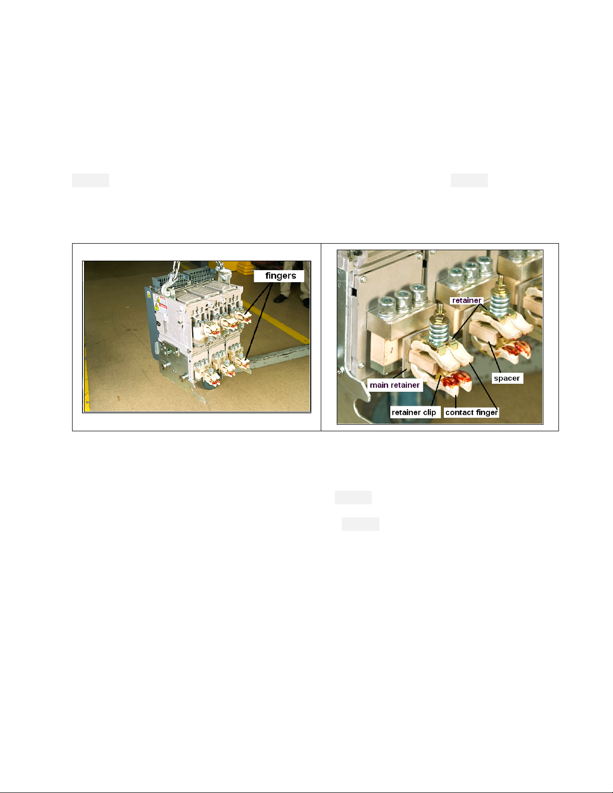
Description
The finger cluster assemblies are spring-loaded, flexible contacts that provide connection between
the breaker line and load terminals, and between the equipment line and load terminals. All finger
cluster assemblies are factory-installed and are assembled on EntelliGuard R Retrofill circuit
breakers. Use this instruction sheet if damaged fingers need to be replaced. It takes about 30
minutes to dismantle and reinstall a new set of finger cluster assemblies on each breaker.
Figure 1 shows finger clusters or primary disconnects on a retrofill circuit breaker. Figure 2 details the
finger-cluster assembly.
Figure 1. Circuit Breaker Removed, Featuring Primary
Disconnects “Fingers” (Contacts)
Figure 2. Circuit Breaker, Fingers (Some Details)
Assembly and Components
The finger cluster assemblies are factory-adjusted with a gage to apply a 105-lb force to a 1/2-inch
thick copper bar, inserted between the upper and lower fingers. Set this force range, in the field, by
tightening the nuts to set the spring dimension shown in Figure 3. Note that this dimension is
measured between the top of the retainer and the underside of the washer. Also note that no bar is
inserted between the fingers when setting this dimension. Figure 4 calls out cluster components.
Page 5

4 Finger Clusters (Assemblies) Accessory Manual DEH-41533 02/12
Figure 3. Adjustment
Figure 4. Components
Remove
1. Using proper safety procedures and wearing required Personal Protective Equipment (PPE),
remove breaker from compartment, and place it on a solid work surface in a well-lit location.
2. To uninstall the primary disconnects, remove the two nuts from one of the long bolts holding
the primary disconnect assembly together.
3. Carefully slide out the bolt while removing the flat washer, spring, bushing, upper retainer, bowtie spacers, lower retainer, and fingers from the bottom of the assembly.
4. Do the same for the other assembly bolt and components.
5. Slide off the retainer clips.
6. Take off the main retainer from the stud.
Replace
1. Slide the main retainer over the stud.
2. Install eccentric spacer and position spring clips on the stud.
3. Set a pair of bow-tie spacers into a pair of fingers, place a pressure plate retainer over the
spacers to hold them in position, and then turn the subassembly over. Hook them into the main
retainer.
4. Slide a long bolt through the hole in the retainer, between the finger, and then through the clip
and eccentric stud spacer.
5. Hold the bottom finger subassembly in place.
6. Place two fingers around the bolt from the top, hooking the fingers into the main retainer. Then
place a bow-tie spacer in each finger and hold them in position with a pressure plate retainer.
7. Place a spring, bushing, and flat washer over the bolt, then secure with the two nuts.
8. Do Steps 1 through 7 for each set of fingers.
9. Adjust the nut to get a spacing of 0.766—0.797 inch between the top of the upper retainer and
the bottom of the flat washer.
Page 6

5 Finger Clusters (Assemblies) Accessory Manual DEH-41533 02/12
10. Tighten the jam nut to lock in the adjustment.
11. Clean finger assemblies, if necessary, with a clean, lint-free rag and isopropyl alcohol or
acetone.
12. Be sure to apply a thin film of Mobilgrease 28 (D50HD38) to the contact areas which slide onto
the switchgear stabs (See Figure 5, Step 2). This product is available in a 1-oz tube,
GE Part #193A1751P1.
Figure 5 summarizes the steps for working with the primary contacts.
Figure 5. Steps in Exploded Views
Page 7

6 Finger Clusters (Assemblies) Accessory Manual DEH-41533 02/12
Mechanical Views
Figure 6 provides further details.
Figure 6. Fingers or Clusters, Mechanical View, and Notes
Page 8

7 Finger Clusters (Assemblies) Accessory Manual DEH-41533 02/12
Figure 6. Fingers or Clusters, Mechanical View, and Notes (continued)
Notes:
1. With text fixtures between upper and lower
pairs of Item 2, tighten Item 11 until force on
fixture is 95 ± 10 lbs. [422.6 ± 44.2 N] and test
fixture thickness is 0.500 inches [12.70 mm].
2. With 0.500 inches [12.70 mm] thick test bar
between upper and lower pairs of Item 2, the
clearance between all fingers (Item 2 and
Item 4) should be 0.020 inches [0.50 mm]
minimum.
3. With text fixture or test bar removed, the gap
between the fingers (Item 2) should be
0.400 inches [10.20 mm].
4. Distance "D" range is 0.766 to 0.797 inches
[19.50 to 20.24 mm]. Note that no bar is
inserted between the fingers when setting
this dimension.
5. See higher ASM. View for proper orientation
of parts.
Page 9

8 Finger Clusters (Assemblies) Accessory Manual DEH-41533 02/12
Figure 6. Fingers or Clusters, Mechanical View, and Notes (continued)
Ordering Information
To order finger cluster for a particular breaker, refer to the cluster part numbers when ordering.
Switchgear
Retrofill Finger Cluster
Quantity
Cluster Part Numbers
AK25
4 x 6 = 24 per CB
10102784G1
AK/AKS 50
8 x 6 = 48 per CB
10102784G2
AKD6-AKR30/30H
4 x 6 = 24 per CB
10105291G1
AKD6-AKR50/50H
8 x 6 = 48 per CB
192A9668G1
AKD8-AKR30/30H
4 x 6 = 24 per CB
10105291G1
AKD8-AKR50/50H
8 x 6 = 48 per CB
192A9668G1
AKD8-AKR30L
8 x 6 = 48 per CB (65kA)
192A9668G1
AKD8-AKR30S
4 x 6 = 24 per CB
10105967G1
All SKU
10107842P1
All apply to the retrofill side.
Page 10

9 Finger Clusters (Assemblies) Accessory Manual DEH-41533 02/12
Notes
Page 11

GE Energy
41 Woodford Avenue
Plainville, CT 06062
www.geindustrial.com
© 2012 GE Company
imagination at work
DEH-41533 02/12
 Loading...