

Page 1
DEH40920 Installation Instructions
g
Motor Operator, Type FCEMF3,
FCEMF6, FCEMFF, FCEMFG
Congratulations and thank you for choosing the
Record Plus™
breakers. The UL-listed type motor operator kit for
catalogs shown in Table 1 is suitable for use with
the FC100 circuit breaker series.
Record Plus™
a full line of integrated accessories. All units use
the latest in integrated modular circuit breaker
technology for flexibility in application and
maximizing the product’s utilization and
capabilities.
All
Record Plus™
Underwriters Laboratories to the UL489 standard
and the CSA Standard C22.2, No. 5. These circuit
breakers are certified to IEC60947-2.
family of current-limiting circuit
circuit breakers are designed with
circuit breakers are listed by
Record Plus
™
Molded Case Circuit Breaker
Accessories
These accessories are also for use with our MAGBREAK® instantaneous trip-only circuit breakers,
which meet the same standards and are ULrecognized components for use in motor
applications. They can also be used with our
molded case switches, which are listed per
Underwriters Laboratories to the UL489 standard.
Record Plus™
accessories are designed and manufactured to
exceed our global customers’ high standards for
reliability and quality.
WARNING
injury. Ensure that ALL electrical power
supplies are OFF before installing or removing
any devices. The breaker, trip unit, or
accessories MUST ONLY be installed and
serviced by QUALIFIED personnel. See NEMA
publication AB4.
AVERTISSEMENT: Danger contre les risques
d'électrocutions. S'assurer avant TOUTES
manipulations du disjoncteur que les
différentes sources d'alimentation sont en
position OFF. Les disjoncteurs, unités de
protection, ou accessories doivent être installés
par des personnes qualifiées et habilitées. Lira
NEMA publication AB4.
: DANGER of electrical shock or
circuit breakers and their
CAUTION:
use in equipment not specifically design to
accept it. Contact the equipment manufacturer
for possible equipment modifications.
ATTENTION:
employe dans un equipement non
specialement adapte a cet effet. Contactez le
constructeur concernant les possibles
modifications a apporter a l'equipement.
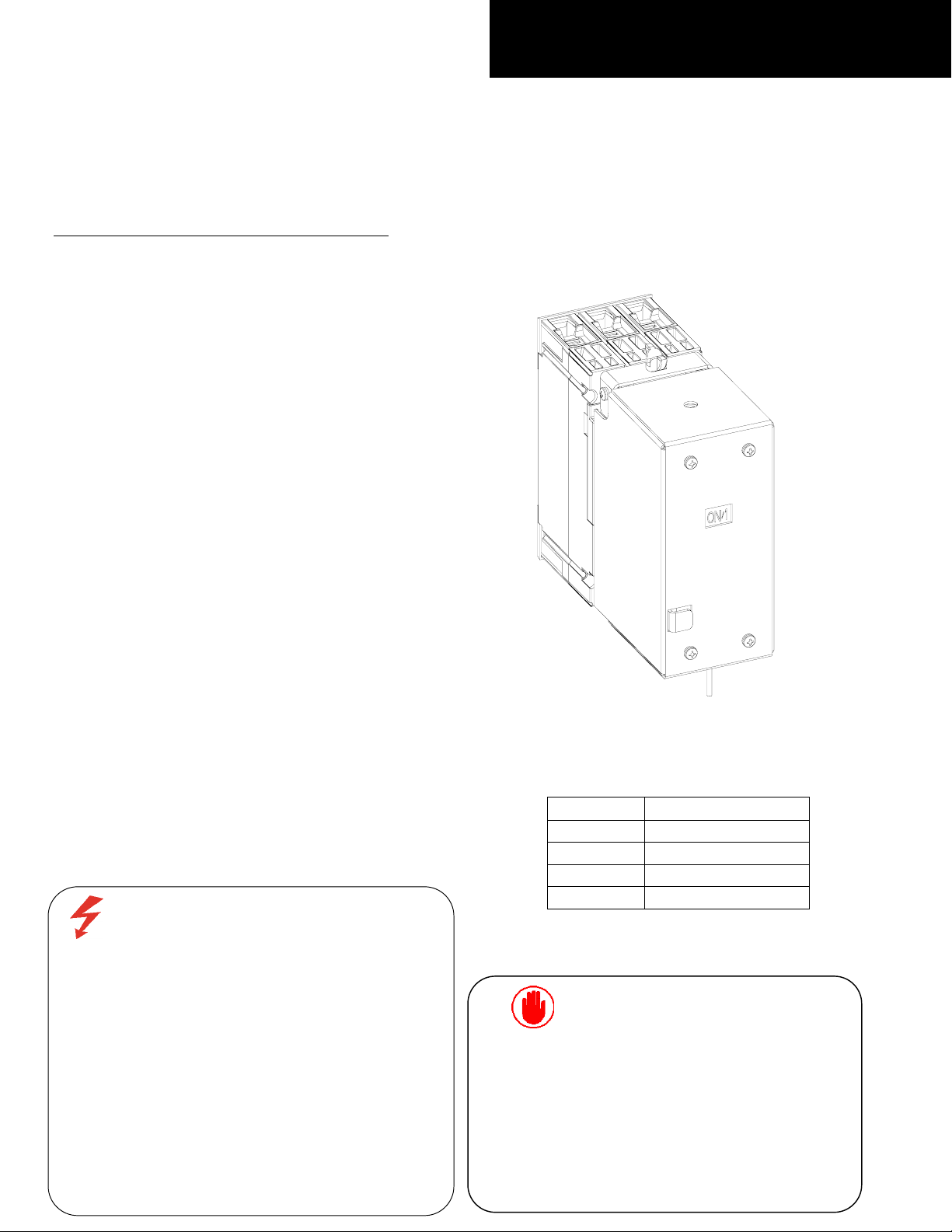
Figure 1. Motor operating Mechanism mounted on
5HFRUG3OXV FC100 circuit breaker.
Catalog Rating
FCEMF3 120V AC/ 125V DC
FCEMF6 240V AC/ 250V DC
FCEMFF 24V DC
FCEMFG 48V DC
Table 1. Catalog Details
This product is NOT suitable for
Cet appareil nedoit pas etre
Page 2
[9]
[4,5]
[8]
[7]
[1]
[2]
[3,5]
[1]
[2]
[3]
[6]
Product Description
These instructions describe the installation
procedures for the Motor Operator Mechanism
accessory on
Record Plus™
circuit breakers, as
illustrated in Figure 1.
The complete kits are available in the catalog
numbers mentioned in Table 1.
The kit is common to all the catalogs, providing
the necessary parts for mounting the motor
operator mechanism on the breaker as shown in
Figure 2.
Step 1 – Unpack and Inspect
Unpack the Motor operating mechanism kit and
inspect the parts for any shipping damage. Verify
that all parts are supplied, as listed in
parts are illustrated in Figure 2.
Note that the numbers in brackets in the following
figures and installation instructions refer to the
item numbers in Table 2.
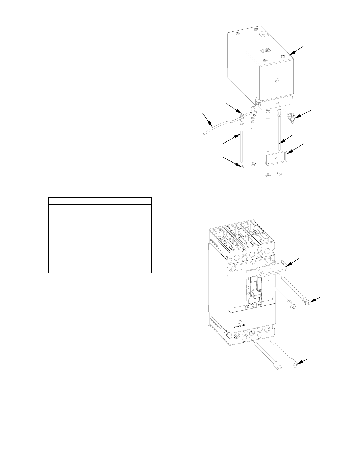
Item Description Qty.
1 Top Bolting Plate 1
2 Mounting Screw 2
3 Screw, #8-32 x 3.50" 2
4 Screw, #8-32 x 0.375" 2
5 Lock Washer 4
6 Nut, Hex #8-32 4
7 Wing Screw #10-24 1
8 Grounding Wire 1
9 Motor Operator
Mechanism
Table 2. List of parts included in the Motor operator
Mechanism kit.
Table 2. The
1
Figure 2. Parts supplied in the Motor operator kits.
Step 2 – Install the Breaker and
Motor Operating Mechanism
1. Move the breaker handle to the OFF position.
2. Mount the breaker with mounting screws[2],
# 8-32
plate[1], as illustrated in Figure 3. Tighten the
screws to 16 - 20 in-lb.
of the circuit breaker according to installation
instructions DEH40463.
3. Position the Mounting bracket of motor
operator assembly on the breaker, as illustrated
in Figure 4. Insert two #8-32 x 0.375" screws
[4] through the mounting holes in the
mounting bracket and into the heads of the
breaker mounting screws [1], with the
grounding wire [8] attached to one of the
screws. Tighten the screws to 16 - 20 in-lb.
Secure the other end of the grounding wire to a
suitable ground location.
x 3.50" screws [3] and Top bolting
Complete the installation
Figure 3. Mounting the breaker.
Page 3

4. Align the Mounting brackets parallel to each
A
A
[4,5,8]
[7]
A
other as shown in Figure 5.
Align the breaker handle with the operator
5.
mechanism, by adjusting the mechanism
position with the screw as shown in Figure 4
Close the operator and fasten the wing
screw [7]
Step 3 – Operation
Description
A motor Operated mechanism is designed to
open, close, and reset a circuit breaker by remote
control.
In an operating installation, the customer must
supply normally open ON and OFF push –
buttons, external wiring, a control power source
and any control circuitry.
ACCESS TO SCREW, FOR
MECHANISM ADJUSTMENT
‘OFF’ SIDE
LIGN BREAKER
HANDLE TO THIS
REA
Electrical Operation
With the breaker and operating mechanism in
their OFF positions, press ON button to energize
the motor, closing the breaker. When the breaker
handle reaches the ON position, an internal limit
switch disconnects the control circuitry.
When the OFF button is pressed, the motor is
energized, opening the breaker. After the breaker
handle reaches the OFF position, a limit switch deenergizes the control circuit.
When the circuit breaker trips automatically, there
is no external trip indication, unless a separate bell
alarm accessory is provided to actuate a warning
device. It is necessary to press OFF to reset the
breaker.
Automatic Reset
For automatic reset, an auxiliary switch, available
as an accessory, returns the breaker to the
OFF/RESET position after it has tripped. The
switch is mounted inside the breaker and wired in
parallel with the OFF button. When the breaker
trips, the switch closes, moving the breaker handle
to OFF/RESET position. After the motor-operated
mechanism has reset the breaker, the limit switch
again opens the circuit. To use automatic reset,
the ON push – button must be SPDT type and
wired as in Figure 7. (The Auto/ Reset scheme
applies to AC devices only and is not applicable to
DC applications).
MOUNTING
BRACKET
Figure 4. Mounting of Motor Operating Mechanism on
Breaker
PARALLEL
LIGNMENT
Manual Operation
Unscrew the wing nut and lift the operator to
disengage the handle and operate the breaker
handle. To return to electrical operation, align
the breaker handle with the operator mechanism
and close the operator and fasten the wing screw.
Figure 6 is the outline view of completed
installations with dimensions.
Figure 5. Alignment of mounting brackets
Page 4

Electrical Data
Table 3 contains the electrical specifications for
the motor operated mechanism.
Catalog
No.
FCEMF3
FCEMF6
FCEMFF 24V AC 31.0 15.5
FCEMFG 48V DC 20.0 7.0
Volts
120V AC 10.5 5.0
125V DC 13.5 4.0
240V AC 6.5 3.0
250V DC 8.0 2.5
Control Timing (Sec)
In-Rush
Amps
Running
Amps
Table 3. Electrical Specifications
Closing
Opening
.15 .13
Recommended
UL Listed Fuse
1 Amp
Time Delay
2 Amp
Time Delay
Figure 6. Outline view of completed installations with dimensions.
Page 5

Figure 7. Wiring diagram for the FC100 Motor Operating Mechanism
Page 6

r
These instructions do not cover all details or variations in equipment nor do they provide for every possible
contingency that may be met in connection with installation, operation, or maintenance. Should furthe
information be desired or should particular problems arise that are not covered sufficiently for the purchaser’s
purposes, the matter should be referred to the GE Company. The circuit breaker is a sealed unit that contains no
user-serviceable parts. Tampering with the seal will void the warranty.
g
________________________________________________________
General Electric Company
41 Woodford Ave., Plainville, CT 06062
www.geindustrial.com
DEH40920 R01 0704 © 2003 General Electric Company
GE Consumer & Industrial
 Loading...