

Page 1
DEH40324 Installation Instructions
g
Record Plus™
Molded Case Circuit Breaker
Accessories
Auxiliary and Bell Alarm Switches
Congratulations and thank you for choosing the
Record Plus™ family of current-limiting circuit
breakers. These UL-listed auxiliary and bell alarm
switches are suitable for use with the FB100, FC100,
FE150, FE250, FG400, and FG600
series.
Record Plus™ circuit breakers are designed with a
full line of integrated accessories. All units use the
latest in integrated modular circuit breaker
technology for flexibility in application and
maximizing the product’s utilization and
capabilities.
Record Plus™ circuit breakers are all listed by
Underwriters Laboratories to the UL489 standard
and may be listed to CSA Standard C22.2, No. 5
and IEC60947-2.
They can also be used with our molded case
switches, which are listed per Underwriters
Laboratories to the UL489 standard.
Record Plus™ circuit breakers and their accessories
are designed and manufactured to exceed our
global customers’ high standards for reliability and
quality.
WARNING: DANGER of electrical shock or injury.
Ensure that ALL electrical power supplies are OFF
before installing or removing any devices. The
breaker, trip unit, or accessories MUST ONLY be
installed and serviced by QUALIFIED personnel. See
NEMA publication AB4.
AVERTISSEMENT: Danger contre les risques
d'électrocutions. S'assurer avant TOUTES
manipulations du disjoncteur que les différentes
sources d'alimentation sont en position OFF. Les
disjoncteurs, unités de protection, ou accessoires
doivent être installés par des personnes qualifiées et
habilitées. Lira NEMA publication AB4.
circuit breaker
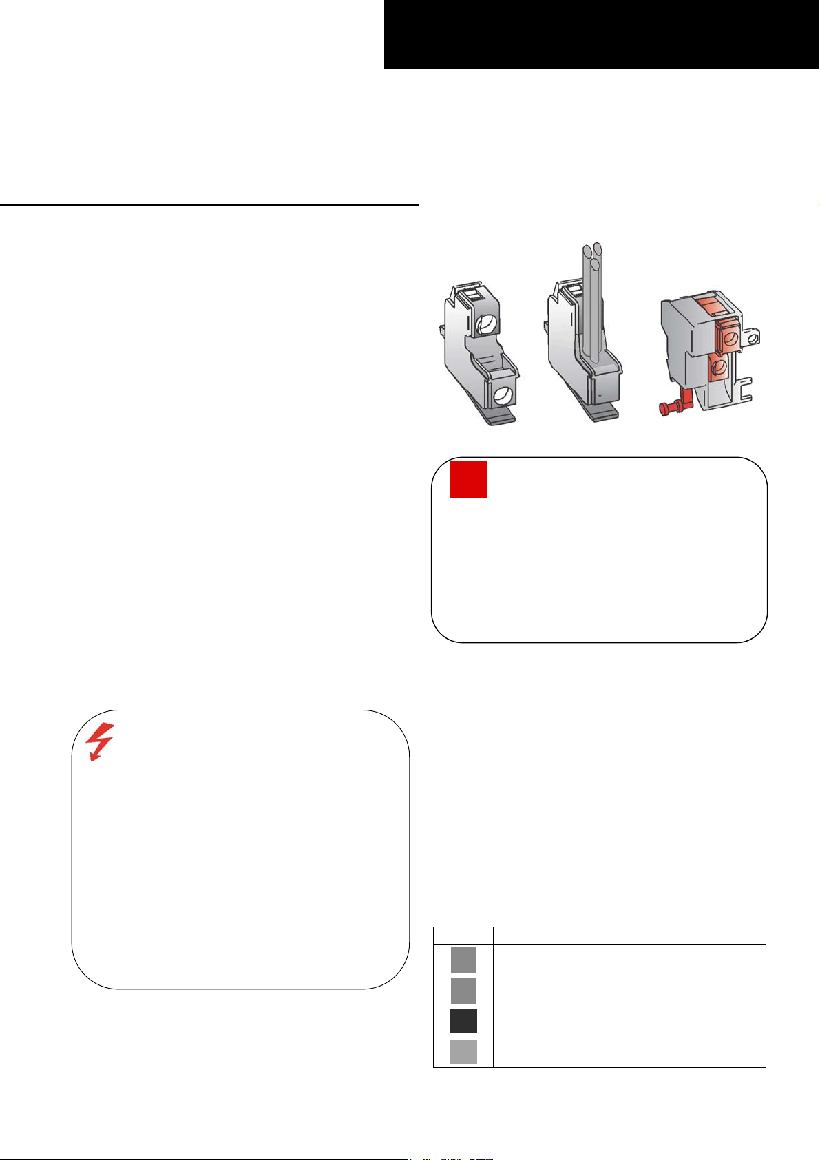
Figure 1. Bell alarm and auxiliary switches.
CAUTION: This product is NOT suitable for use in
equipment not specifically design to accept it.
Contact the equipment manufacturer for possible
equipment modifications.
ATTENTION: Cet appareil nedoit pas etre employe
dans un equipement non
effet. Contactez le constructeur concernant les
possibles modifications a apporter a l'equipement.
Product Description
The auxiliary and bell alarm switches covered by these
instructions are illustrated in Figure 1. A key for the
different symbols used in these instructions is found in
Table 1. Catalog numbers for the various switch
configurations are listed in Table 2.
Note that contact position for the auxiliary switch is
shown with the breaker in the open position. Bell alarm
contact position is shown with the breaker in the
untripped position.
Mechanical-trip bell alarms are activated by the trip unit
(overcurrent or short circuit), undervoltage release,
shunt trip, or push-to-trip button. Overcurrent/shortcircuit trip bell alarms are activated by the trip unit on
and are not available for FB and FC breakers.
Symbol Description
Right-hand pocket auxiliary switch
Left-hand pocket auxiliary switch
Mechanical-trip bell alarm (all tripping
functions)
Overcurrent / short-circuit trip bell alarm
(not available on FC breakers)
specialement adapte a cet
ly
Table 1. Key to symbols.
Page 2
Bell Alarm Switches Auxiliary Switches Switch Symbols
IEC UL/CSA
FABAM10 FABAT10 FAS10L FAS10R
FABAM01 FABAT01 FAS01L FAS01R
FABAM11 FABAT11 FAS11L FAS11R
Table 2. Catalog numbers for Record Plus™ auxiliary and bell alarm switches.
Step 1 – Unpack and Inspect
Unpack the bell alarm or auxiliary switch kit and inspect
it for shipping damage. Read the circuit breaker
installation instructions carefully. Insure that the circuit
breaker and the accessory have the proper rating
current, voltage, interruption, and contact duty; wire
routing; installation; and operation for the application.
Form C switches are factory installed with #18 AWG
wires, 36 inches long. All other switches with the catalog
number suffix W ar
e factory installed with #16 AWG
wire, 36 inches long.
Wire colors for each switch catalog number are listed in
Table 3. Contact ratings for Form C switches are listed
in Table 4. Contact ratings for Form A and B switches
are listed in Table 5.
Commo
Cat. No.
FAS01L White Brown/White
FAS10L White Red
FAS11L White Brown/White Red
FAS01R White Brown/White
FAS10R White Red
FAS11R White Brown/White Red
FABAT01 Orange Pink
FABAT10 Orange Grey
FABAT11 Orange Pink Grey
FABAM01 Yellow Purple
FABAM10 Yellow Brown
FABAM11 Yellow Purple Brown
n
1
NC
2 4
Table 3. Wire colors for auxiliary and bell alarm switches.
Vac A Vdc A
Low-energy gold-plated contacts,
catalog number suffix G
5 1 5 1
12 1 12 1
24 1 24 1
30 1 30 1
Standard contacts
48 5 48 0.3
60 5 60 0.3
120 5 110 0.3
220 5 125 0.3
240 5
277 5
s for
NO
4
Form A
Vac A Vdc A
A600/AC15 Q300/DC13
12 10* 12 2.5
24 10* 24 2.5
48 10* 48 1.1
60 10* 60 1
110 6* 110 0.55
120 6* 125 0.55
220 3 220 0.27
240 3 250 0.27
380
480 1.5
500
600 1.2
Maximum VA:
Making – 7200 VA
Breaking – 720 VA
Maximum Thermal
Current = 10 A
* 5 A for screw-type
terminals
Minimum low-energy switching: IEC609747-5-4
12 5 mA 12 5 mA
1.9 (2.0
for AC15)
1.4 (1.5
for AC15)
Form B
Form C
300
Maximum VA = 69 VA
Maximum Thermal
Current = 69 VA
0.2 for
DC13
Table 5. Contact ratings for Form A and B switches; cat. nos.
FA/FEBAT10/01, FABAM10/01, FAS10L/01L, FAS10R/01R.
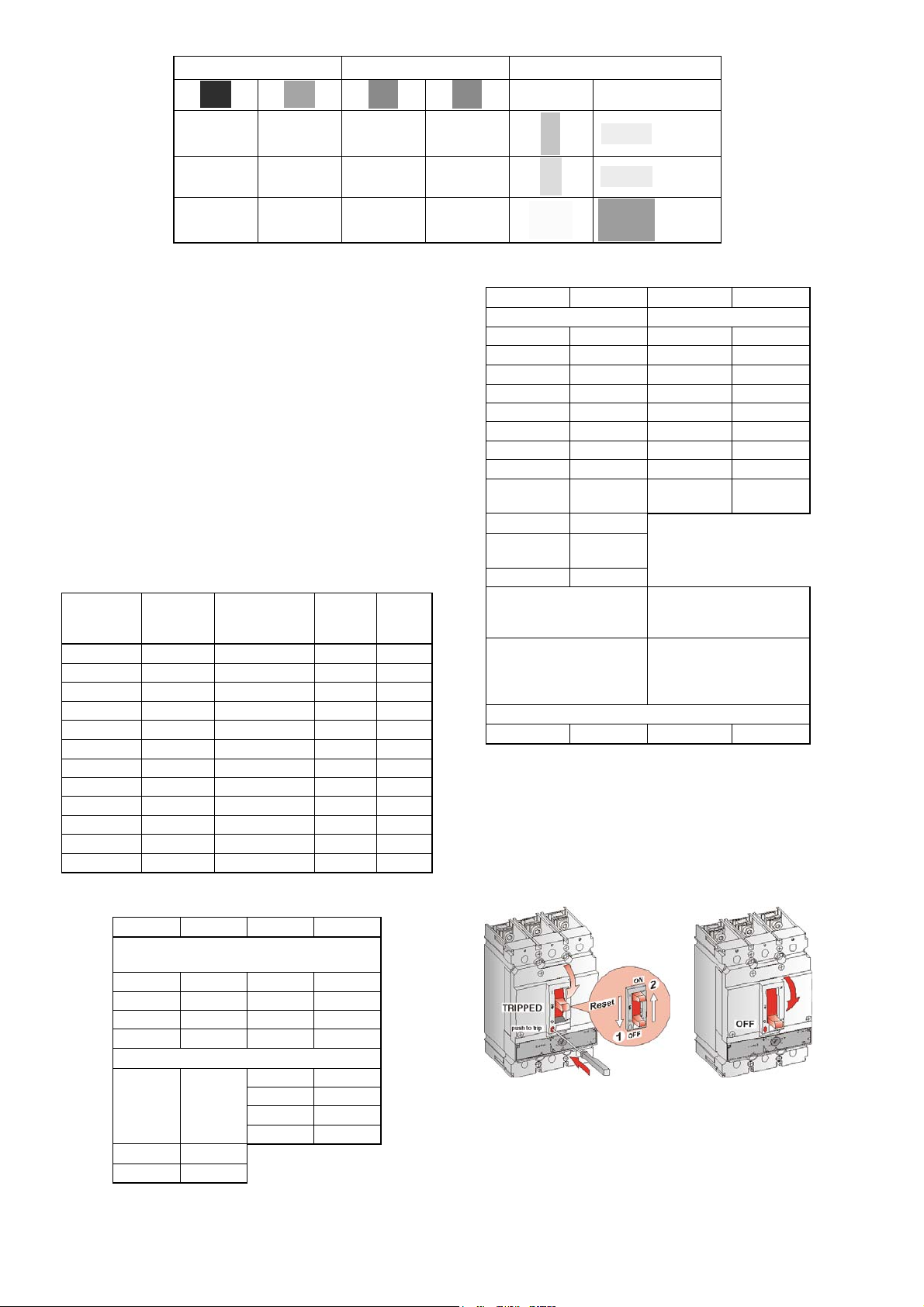
Step 2 – Breaker Status
Either trip the circuit breaker by activating the red trip
button on the front of the breaker or move the breaker
handle to the
Figure 2. (a) Tripping the breaker or (b) turning it OFF.
OFF position, both shown in Figure 2.
(a)
(b)
Table 4. Contact ratings for Form C switches; cat. nos. FA/FEBAT11,
FABAM11, FAS11L, FAS11R.
Page 3

Step 3 – Installation
-
1. Loosen, but do not remove, the captive screws
holding the accessory cover on the breaker, as
shown in Figure 3. Remove the cover.
2. Each switch snaps into place in its designated
pocket, as shown in Figure 4(a). It can also be
easily removed with the aid of a small screwdriver,
as shown. The proper pockets for each
illustrated in
Figure 5 for FB/FC breakers
6 for FE breakers and in Figure 7 for FG beake
rs. Each breaker pocket is clearly marked with
the symbol for the device that it accepts.
3. If the accessory was not factory wired, connect the
wires to the lugs on the accessory, as shown in
Figure 4
(b). For screw-type terminals, the
recommended wire size is #24–16 AWG (0.4–2.5
2
), with 600-V insulation, and a maximum
mm
diameter of 0.100 in. (2.54 mm). Tighten the
terminals to 11 lb-in (1.2 Nm).
device are
, in Fig
ure
Figure 5. Accessory locations in FB/FC circuit breakers.
Figure 3. Removing the accessory cover.
0.4–2.5 mm
24–16 AWG
1.0 Nm
9 lb-in
(a)
(b)
Figure 4. (a) Installing and removing a snap-fit accessory.
(b
) Atta
g the wiring to the a
chin
ccessory.
FE Breaker with
Electronic Trip Unit
FE Breaker with Thermal
Magnetic Trip
2
Figure 6. Accessory locations in FE circuit breakers.
FG 400
FAS...L
0 - 3 max
FABAM...
mechanism
FAS...R
0 - 2 max
FABAT...
trip
FG 600
L
0
0
4
0
3
A
A
T
FG
mxr
l
%
=
5
0
l
1
=
t
>
.
S
.
5.
9%
=
>
t
A4
S
0
0
6
5
0
r
l
8
04 A
4
10
5.
80
8
.
3
0
R
M1
S
2
r
1
l
L
0
0
4
3
et
9
.
Ts
0
RS
7
E
.
5.
F
0 5
2
3
1
2
A0
0
4
m
I
7
.
0
9
A
.
0
05
5
2
5
1
.60
A
5
20
M
A0
0
4
Figure 7. Accessory locations in FG circuit breakers.
Page 4

Step 4 – Wire Routing, Cover
Knockouts, and Port Wiring
Determine the wire routing, as shown in Figure 8, as
follows:
• For an FB/FC breaker, use ports B, F, D, and H.
• For an FE/FG breaker, use a sharp knife or wire
cutter to remove the knockouts in the breaker
accessory cover.
Route the accessory wiring out of the breaker through
the exit ports, being careful to dress the wiring from the
accessory without pinching the insulation.
Table 6 lists the maximum number of wires allowed per
port. The maximum number of wires per port is based
on an insulation outside diameter of 0.100 in. (2.54
mm). Scale the given number of wires up or down for
wires with a different diameter.
Port FB/FC Breaker FE/FG Breaker
A, E N/A 8
B, F B: 5; F: 9 5
C, G N/A 3
D/ H 4 6
Table 6. Maximum number of accessory wires allowed per port.
WARNING: It is important that the cover is installed
correctly to ensure proper circuit breaker operation.
AVERTISSEMENT: Il es important de verifier que
tout cuvercle ou cache de protection est
correctement installe afin d’assurer le bon
fonctionnement de l’appareil.
Step 5 – Attach the Label and
Replace the Breaker Cover
Attach the accessory label to the side of the breaker, as
illustrated in Figure 8, for each internal accessory
installed.
Replace the breaker cover, as illustrated in Figure 3.
Tighten the mounting screws to 11 lb-in (1.2 Nm).
Complete the installation by performing an operational
check.
Figure 8. Wire routing and port knockouts.
These instructions do not cover all details or variations in equipment nor do they provide for every possible contingency
that may be met in connection with installation, operation, or maintenance. Should further information be desired or
should particular problems arise that are not covered sufficiently for the purchaser’s purposes, the matter should be
referred to the GE Company. The circuit breaker is a sealed unit that contains no user-serviceable parts. Tampering
with the seal will void the warranty.
GE Industrial Systems
General Electric Company
41 Woodford Ave., Plainville, CT 06062
www.geindustrial.com
DEH40324 R03 0808 © 2003 General Electric Company
g
 Loading...