

Page 1

GE Energy
Industrial Solutions
EPM 4500
SUB METER
Instruction Manual
Manual P/N: 1601-0157-A9
Manual Order Code: GEK-106555I
Copyright © 2010 GE Energy
GE Energy
Industrial Solutions
41 Woodford Avenue
Plainville, CT 06062
Internet: http://www.geindustrial.com
Page 2

Page 3

Table of Contents
1: OVERVIEW GETTING STARTED ........................................................................................................................... 1-1
ESCRIPTION ........................................................................................................................ 1-1
D
APPLICATIONS ................................................................................................................................... 1-2
TAND-ALONE METER ........................................................................................................ 1-2
S
ETERING SYSTEM .............................................................................................................. 1-2
M
NTERIOR VIEW ....................................................................................................................1-3
I
AUTIONS AND WARNINGS ............................................................................................... 1-3
C
ROTECTIVE CONDUCTOR TERMINAL ............................................................................... 1-4
P
REVENTIVE MAINTENANCE ............................................................................................... 1-4
P
SPECIFICATIONS ............................................................................................................................... 1-5
ONITORING ........................................................................................................................ 1-5
M
OWER SUPPLY ................................................................................................................... 1-5
P
ETERING ............................................................................................................................. 1-5
M
NPUTS .................................................................................................................................. 1-6
I
OMMUNICATIONS .............................................................................................................. 1-6
C
HYSICAL .............................................................................................................................. 1-6
P
YPE TESTS AND APPROVALS ............................................................................................ 1-6
T
ORDERING ........................................................................................................................................... 1-8
EPM4500 R
EPM4500 C
PTIONS ...............................................................................................................................1-8
O
URRENT TRANSFORMERS (0.1 A SECONDARY) .............................................................1-9
C
RANSPONDER MODELS .....................................................................................................1-9
T
ULSE INPUTS ...................................................................................................................... 1-9
P
ESIDENTIAL .................................................................................................... 1-8
OMMERCIAL ................................................................................................... 1-8
2: INSTALLATION GETTING READY ................................................................................................................................ 2-1
ETERMINATION OF METERING SYSTEM REQUIREMENTS .............................................. 2-1
D
HASE ASSOCIATION ........................................................................................................... 2-1
P
WIRING ................................................................................................................................................. 2-2
VERVIEW OF METER WIRING .......................................................................................... 2-2
O
IRING OVERVIEW ............................................................................................................. 2-2
W
HREE-PHASE FOUR-WIRE WYE WIRING ....................................................................... 2-3
T
INGLE-PHASE, THREE-WIRE 120 V WIRING ............................................................... 2-6
S
HREE-PHASE, THREE-WIRE DELTA WIRING ................................................................. 2-9
T
INGLE-PHASE, THREE-WIRE WIRING ............................................................................. 2-12
S
INSTALLATION OF METER, MCI BOARD, AND CTS .............................................................2-15
ROCEDURE .......................................................................................................................... 2-15
P
INSTALLING THE SCAN TRANSPONDER ................................................................................. 2-18
ROCEDURE .......................................................................................................................... 2-18
P
3: USING THE METER MENU NAVIGATION ........................................................................................................................ 3-1
SER INTERFACE ..................................................................................................................3-1
U
CT MULTIPLIER TABLE .................................................................................................................... 3-4
ULTIPLIERS .................................................................................................................. 3-4
CT M
VERIFYING METER FUNCTIONALITY ......................................................................................... 3-5
VERVIEW ............................................................................................................................ 3-5
O
EPM 4500 SUB METER – INSTRUCTION MANUAL TOCTOC–I
Page 4

VERIFYING VOLTAGE ...........................................................................................................3-5
ERIFYING KWH READING ................................................................................................. 3-5
V
ERIFYING CURRENT AND ENERGY ................................................................................... 3-6
V
RESETTING THE DEMAND VALUES ........................................................................................... 3-7
ROCEDURE ..........................................................................................................................3-7
P
4: COMMUNICATIONS MODBUS COMMUNICATIONS ..................................................................................................... 4-1
RS485 W
RS232 W
ODBUS COMMANDS ......................................................................................................... 4-2
M
IXED MODBUS VALUES ..................................................................................................... 4-2
F
ODBUS DATA REGISTER (R4 TYPE) GROUPS ................................................................ 4-3
M
NSTANTANEOUS DATA ITEMS ............................................................................................4-3
I
32-
IRING FOR MODBUS ......................................................................................... 4-1
IRING FOR MODBUS ......................................................................................... 4-2
BIT LONG AND FLOAT DATA FORMATS ..................................................................... 4-4
MODBUS ACTIVATION .................................................................................................................... 4-5
VERVIEW ............................................................................................................................ 4-5
O
ONFIGURING A NEW HYPERTERMINAL SESSION .......................................................... 4-5
C
ONFIRMING CONNECTION TO THE EPM4500 .............................................................4-6
C
OGGING INTO THE METER ................................................................................................ 4-6
L
CTIVATING MODBUS COMMUNICATIONS ....................................................................... 4-7
A
HANGING MODBUS SETTINGS ......................................................................................... 4-8
C
OGGING OUT ...................................................................................................................... 4-8
L
ISABLING MODBUS COMMUNICATIONS ......................................................................... 4-8
D
MODBUS MEMORY MAP ................................................................................................................ 4-9
EMORY MAP ......................................................................................................................4-9
M
5: MISCELLANEOUS REVISION HISTORY .......................................................................................................................... 5-1
ELEASE DATES ...................................................................................................................5-1
R
HANGES TO THE MANUAL ................................................................................................ 5-2
C
WARRANTY ......................................................................................................................................... 5-4
NERGY WARRANTY ..................................................................................................... 5-4
GE E
TOCTOC–II EPM 4500 SUB METER – INSTRUCTION MANUAL
Page 5

GE Energy
Industrial Solutions
709710A1.CDR
1.1 Getting Started
EPM4500 Sub Meter
Chapter 1: Overview
Overview
1.1.1 Description
Thank you for purchasing the GE Energy EPM4500 24-point sub-meter to monitor energy
for your residential, commercial, or industrial applications. At GE Energy, we pride
ourselves by providing our customers with best-in-class products, which have been
carefully selected by GE to best serve your solution needs.
The EPM4500 is sold in KWh or Demand meter versions and is available for 120/208V and
277/480V applications. An integrated liquid crystal display (LCD) is standard on all versions,
providing local access to real-time and historical data. The meter provides two standard
communication modes: power line communications (PLC), which utilizes existing AC power
lines as the communication medium, eliminating dedicated wiring, and Modbus (RS232,
RS485, and modem).
The EPM4500 is packaged with either solid or split-core CTs in various amperages to suit
both new construction and retrofit applications.
Note
The EPM4500 is primarily used for commercial and industrial applications and is
available in voltages ranging from 120 to 600 V in both wye and delta forms. The
following installation instructions are applicable to the EPM4500 meter only.
EPM 4500 SUB METER – INSTRUCTION MANUAL 1–1
Page 6
APPLICATIONS CHAPTER 1: OVERVIEW
1.2 Applications
1.2.1 Stand-Alone Meter
The GE Energy EPM4500 can be installed as a stand-alone device that is locally accessed
via the LCD or remotely accessed via modem. A modem can be installed in each meter
allowing the meter(s) to be read remotely.
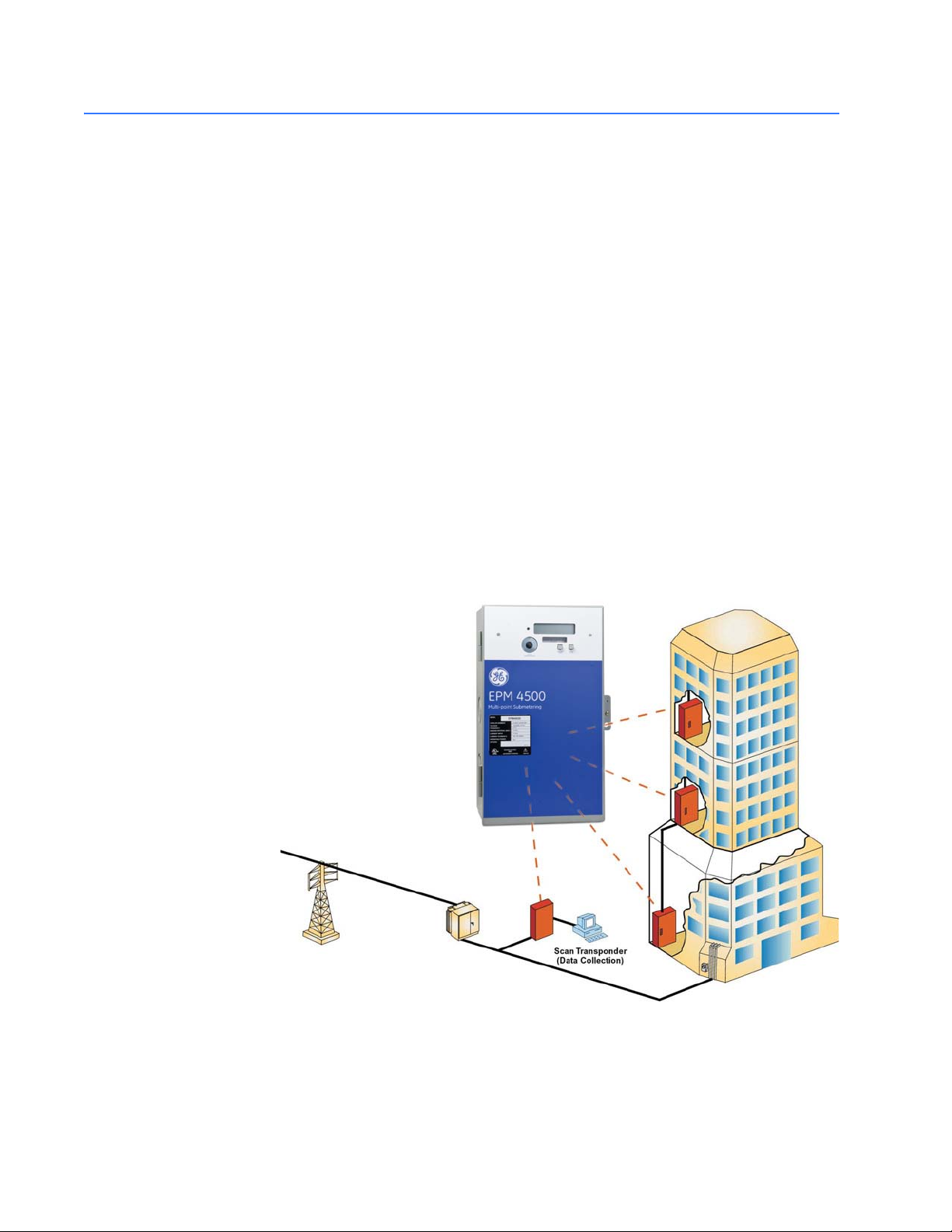
1.2.2 Metering System
The GE Energy EPM4500 family of meters are ideally designed to comprise a metering
system within a residential/commercial building or industrial site. This metering system
can measure electrical usage for each tenant, cost center, or common area space and
communicate this information over the building's power wires or dedicated
communication wiring (RS485). A metering system is comprised of two or more EPM4500
meters and at least one communication transponder (see figure below). The transponder
collects metering data from multiple meters via AC power lines. For larger sites, additional
transponders may be required. Multiple transponders can communicate via a data link
network using RS485 or via a wireless network.
The metering data can be accessed from the transponder or network of transponders
using a telephone modem or local RS232 connection to a PC for data transfers.
709712A1.CDR
FIGURE 1–1: Overview of Scan Transponder Functionality
1–2 EPM 4500 SUB METER – INSTRUCTION MANUAL
Page 7
CHAPTER 1: OVERVIEW APPLICATIONS
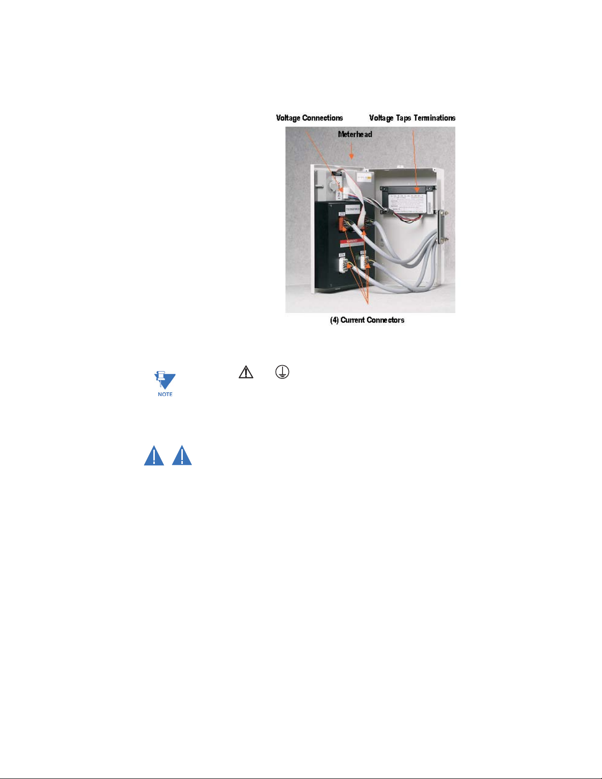
1.2.3 Interior View
The interior of the EPM4500 is shown below.
709711A1.CDR
FIGURE 1–2: Interior View of the EPM4500
Note
Where the and symbols are seen on the EPM4500 meter, the manual must be
consulted to determine the nature of any potential hazard and/or actions to be taken.
1.2.4 Cautions and Warnings
• Do not install if the device is damaged. Inspect the housing for obvious defects
CAUTION
WARNING
such as cracks in the housing.
• If the device is installed or used in a manner not specified by accompanying
documents, the protection of the device may be impaired.
• If the device functions abnormally, proceed with caution. The protection of the
device may be impaired.
• Do not install the meter around combustible gas or gas vapor.
• Do not install the meter in an electrical service with current or voltage outside of
the specified limit of the device.
• Do not operate the meter with the cover removed.
• To avoid electric shock, disconnect mains before replacing fuses!
• See instructions for connection diagram.
• Risk of electric shock. Beware of working around this meter when the voltage is
live.
• For continued protection against fire, replace only with fuses of specified voltage
and current rating.
EPM 4500 SUB METER – INSTRUCTION MANUAL 1–3
Page 8

APPLICATIONS CHAPTER 1: OVERVIEW
1.2.5 Protective Conductor Terminal
Securely fasten one end of the earthing wire so that the screw cuts the paint on the back
box. Securely fasten other end of the wire to a true earth ground connection. When
earthing to the electrical conduit, use continuous pipes, bending when necessary instead
of using couplers.
1.2.6 Preventive Maintenance
There are no necessary preventative maintenance or inspection.
A Toshiba CR2032 coin battery is used in each device and is intended to be good for
decades before replacement. Return to manufacturer for replacement.
1–4 EPM 4500 SUB METER – INSTRUCTION MANUAL
Page 9

CHAPTER 1: OVERVIEW SPECIFICATIONS
1.3 Specifications
1.3.1 Monitoring
DEMAND
Consumption and demand: .....................kW and kWh
Demand reset:.................................................allows local reset of peak demand register
INTERVAL DATA AND PEAK DEMAND
Commercial:......................................................15 minute block demand interval and peak demand with
date and time stamp
Residential:........................................................1 hour block demand interval
DATA LOGGER
Duration:.............................................................120 days with kW and kWh
Battery:................................................................internal battery maintains time and current interval
metering data during power outage only
1.3.2 Power Supply
1.3.3 Metering
CONTROL POWER
Input:....................................................................120 V phase A to neutral
277 V phase A to neutral
480 V phase to phase
(internally powered through metered voltage; no external
source is required)
Frequency:.........................................................50 to 60 Hz
Operating power: ...........................................2 watts for 120 V
5 watts for 277 V and 480 V
Fuses:...................................................................1 - Buss fuse 250 V / 500 V 0.25 A / 0.125 A slow-acting
3 - Buss fuse 250 V /600 V 4.0 A fast-acting
MEASURED VALUES
Real time per phase:.....................................voltage, current, kW, kvar, kVA, power factor, frequency,
phase angle
Data logging:....................................................kWh, kW demand
METER ACCURACY
Accuracy: ...........................................................0.5 class accuracy
±0.5% unity and 50% power factor, 1 to 100% of full-
scale
Standards: .........................................................meets revenue certifiable ANSI C12.1 and C12.16
accuracy standards
LIQUID CRYSTAL DISPLAY (LCD)
Display size:.......................................................32-digit LCD, 16 digits in two rows
Data digit height:............................................0.31"
Consumption register: .................................6 digits
EPM 4500 SUB METER – INSTRUCTION MANUAL 1–5
Page 10

SPECIFICATIONS CHAPTER 1: OVERVIEW
1.3.4 Inputs
AC CURRENT INPUTS
CT input:..............................................................50 to 800 A primary available
Secondary inputs: ..........................................0.1 A or 5 A
AC VOLTAGE INPUTS
Metered voltage:.............................................120/208 V wye, 277/480 V wye, or 600 V delta
at 50 to 60 Hz
Rated voltage:..................................................90 to 110%
PULSE INPUTS
Inputs:..................................................................up to 48 form-A pulse inputs logged in programmable
intervals also count during power outage
Minimum wire gauge:...................................20 AWG
Maximum wire length:.................................300 ft.
Maximum rate: ................................................5 transitions/second
Minimum pulse width:..................................100 ms
1.3.5 Communications
EPM4500 COMMUNICATIONS
Protocols:............................................................Power line communications (PLC)
RS485 Modbus (2-wire, half-duplex, isolated)
Ports: ....................................................................IEC front optical point-of-access (POA) port
1.3.6 Physical
ENVIRONMENT
Usage:..................................................................For indoor use only
Enclosure:...........................................................NEMA 1 rated
Temperature:....................................................–20°C to +60°C
Humidity:............................................................0 to 95% relative humidity (non-condensing)
Pollution degree:.............................................1
Maximum altitude:.........................................2000 m
DIMENSIONS
Meter enclosure:.............................................13.5"H × 8.5"W × 4.5"D
CT terminal board enclosure: 13.5"H × 8.5"W × 4.5"D
SHIPPING
Shipping weight:.............................................1 meter assembly 34 lbs. (total weight)
Shipping dimensions: ...................................2 enclosures, each 13.5"H × 8.5"W × 4.5"D
1.3.7 Type Tests and Approvals
TYPE TESTS
Transient/surge suppression: ANSI C37.90.1-1989
Installation category:....................................III. This product falls under Installation Category III
because of its distribution level, fixed installation and has
smaller transient overvoltages than an Installation
Category IV.
1–6 EPM 4500 SUB METER – INSTRUCTION MANUAL
Page 11

CHAPTER 1: OVERVIEW SPECIFICATIONS
APPROVALS
ANSI: .....................................................................C12.1 and C12.16 accuracy
UL and CUL: ......................................................recognized under E204142
Industry Canada:............................................MC#AE-1148
EPM 4500 SUB METER – INSTRUCTION MANUAL 1–7
Page 12
ORDERING
EPM 4500 SUB METER – INSTRUCTION MANUAL
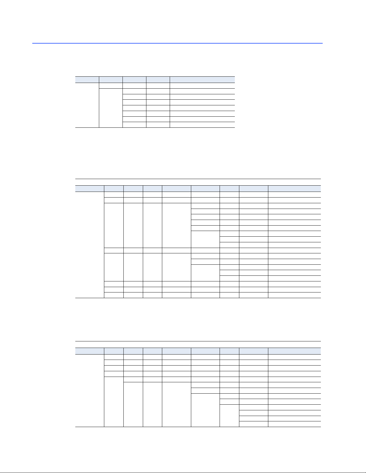
1.4 Ordering
1.4.1 Enclosure
Step 1: Select Enclosure
Family Back Box Voltage Options Description
PL4500 BBA * * Back Box Assembly
1.4.2 EPM 4500 Residential
The EPM 4500 residential package is available in single-phase 120/208 V or 120/240 V connections.
Residential use measures kWh only (no demand measurement).
Step 2: Select required meter head
Family Voltage Phase Wires Application Metering Points CTs Options Description
PL4500 * * * * * * *
CHAPTER 1: OVERVIEW
120V 120/208V 3 phase, 4 wire
208V 208V 3 phase 3 wire
240V 120/240V, 1 phase, 3 wire
277V 277/480V 3 phase, 4 wire
347V 347/600V 3 phase, 4 wire
480V 480V 3 phase 3 wire
E Future Communications Provision
Residential
120 3 4 R 120/208V 3 phase, 4 wire
03 3 Points
06 6 Points
09 9 Points
12 12 Points
24 24 Points
L 0.1 Amps Secondary Input
H 5 Amps Secondary Input
P Pulse Data Input Module
240 1 3 R 120/240V, 1 phase, 3 wire
12 12 Points
24 24 Points
L 0.1 Amps Secondary Input
H 5 Amps Secondary Input
P Pulse Data Input Module
277 277/480V 3 phase, 4 wire
347 347/600V 3 phase, 4 wire
3 4 R 24 L 24 points, 0.1 secondary CTs
1.4.3 EPM 4500 Commercial 4-Wire
The EPM 4500 commercial package is available in three-phase 120/208 V, 277/480 V, or 347/600 V
connections (delta optional). Commercial use measures kWh and kW demand.
Family Voltage Phase Wires Application Metering Points CTs Options Description
PL4500 * * * * * * *
120 120/208V 3 Phase
277 277/480V 3 Phase
347 347/600V 3 Phase
1–8
Commercial 4-Wire
3 4 C 3 Phase 4 wire Commercial
06 6 Points
08 8 Points
L 0.1 Amps Secondary Input
H 5 Amps Secondary Input
P Pulse Data Input Module
M Modem
RS RS485 Connection
MOD Modbus Communication
Page 13

EPM 4500 SUB METER – INSTRUCTION MANUAL
1.4.4 EPM 4500 Commercial 3-Wire
Commercial 3-Wire
Family Voltage Phase Wires Application Metering Points CTs Options Description
PL4500 * * * * * * *
208 208V 3 phase 3 wire
480 480V 3 phase 3 wire
3 3 C 12 12 points
1.4.5 Current Transformers (0.1 A Secondary)
CTs
Type Description Cat. No.
CT-50 (50/0.1A) PLSUBCTSL050
Solid Core - 0.1 A Secondary
Solid Core - Canadian CT-2/5DARL (200A/5A) PLSUBCTSL201CDN
Split Core - 0.1 A Secondary
CT-1 (100/0.1A) PLSUBCTSL101
CT-2 (200/0.1A) PLSUBCTSL201
CT-4 (400/0.1A) PLSUBCTSL401
CTSP-50 (50/0.1A) PLSUBCTSP050
CTSP-1 (100/0.1A) PLSUBCTSP101
CTSP-2 (200/0.1A) PLSUBCTSP201
CTSP-4 (400/0.1A) PLSUBCTSP401
CTSP-8 (800/0.1A) PLSUBCTSP801
CTSP-12 (1200/0.1A) PLSUBCTSP1201
CTSP-20 (2000/0.1A) PLSUBCTSP2001
CTSP-30 (3000/0.1A) PLSUBCTSP3001
CTSP-40 (4000/0.1A) PLSUBCTSP4001
ORDERINGCHAPTER 1: OVERVIEW
L 0.1 Amps Secondary Input
P Pulse Data Module
M Modem
RS RS485 Connection
MOD Modbus Communication
1.4.6 Transponder Models
To order: Select Back Box, then select transponder model with options.
1. Order Back Box
Description Cat. No.
120V service back box TRANS BBA 120V
277V service back box TRANS BBA 277V
347V service back box TRANS BBA 347V
1.4.7 Pulse Inputs
The order codes for the pulse inputs are indicated below.
Cat. No.
PL4500PULSINA
PL4500PULSINB
PL4500PULSINC
PL4500PULSIND
For additional information on pulse inputs, please contact GE Energy.
2. Order Transponder Model with options
Description Cat. No.
120/208V with modem TRANS120M
120/208V with RS485 and RS2332 connections TRANS120RS
277/480V with modem TRANS277M
277/480V with RS485 and RS232 connections TRANS277RS
347/600V with modem TRANS347M
347/600V with RS485 and RS 232 connections TRANS347RS
1–9
Page 14

ORDERING CHAPTER 1: OVERVIEW
1–10 EPM 4500 SUB METER – INSTRUCTION MANUAL
Page 15

GE Energy
Industrial Solutions
709710A1.CDR
2.1 Getting Ready
EPM4500 Sub Meter
Chapter 2: Installation
Installation
2.1.1 Determination of Metering System Requirements
Determine if the application is for a metering system or for a stand-alone meter. If the
application is for a stand-alone meter, please read Overview of Meter Wiring on page 2–2.
If the application is for a metering system, then also read Installing the Scan Transponder
on page 2–18.
2.1.2 Phase Association
As shown in Table 2–1: Wiring Diagram / Model Reference on page 2–3, there are four
wiring types for the EPM4500 meter. Each wiring type has a specific phase association
table to ensure that current transformers are in-phase with the reference voltage. These
phase association tables must be followed for the meter to function properly with the
chosen wiring type.
The phase association of the current transformers must be followed or meter will not
be installed correctly.
EPM 4500 SUB METER – INSTRUCTION MANUAL 2–1
Page 16
WIRING CHAPTER 2: INSTALLATION
2.2 Wiring
2.2.1 Overview of Meter Wiring
Although this document treats the installation and certification stages separately, this
does not imply that the recommended procedure is to install the entire system at once and
then proceed to certification.
The recommended procedure is to install and certify the system in stages. By doing this,
systematic error can be corrected before it propagates through the entire installation. To
follow the recommended procedure, divide the job up into manageable stages and install
and certify at each stage before proceeding to the installation of the next stage.
For the purposes of this discussion, the colors black, red and blue have been chosen to
distinguish among the three phases of a three-phase network. White is the designated
color of neutral and green is the color of earth ground. Please substitute the correct color
according to local electrical code. For a two-phase installation, ignore the third phase (the
blue phase in the following description).
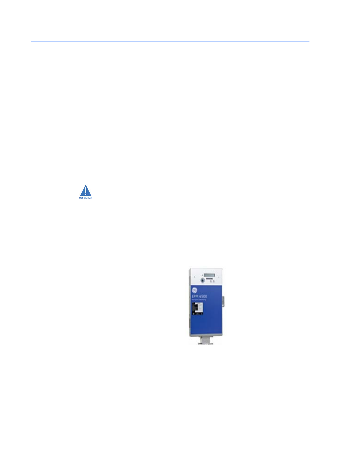
Failure to follow the proper procedures and reference the correct wiring diagram can
result in damage to the equipment and/or physical harm.
709714A1.CDR
FIGURE 2–1: Vertical Mounting Option
2.2.2 Wiring Overview
Review the following wiring types and select the one that matches your installation
requirements and part number using the following table.
2–2 EPM 4500 SUB METER – INSTRUCTION MANUAL
Page 17

Table 2–1: Wiring Diagram / Model Reference
Three-Phase Four-Wire Wye Wiring on page 2–3
Single-Phase, Three-Wire 120 V Wiring on page 2–6
Three-Phase, Three-Wire Delta Wiring on page 2–9
Single-Phase, Three-Wire Wiring on page 2–12
2.2.3 Three-Phase Four-Wire Wye Wiring
The phase association and polarity of the current transformers must be followed or
the meter will not be correctly installed.
1. Current transformers must be in-phase with the reference voltage. The MCI board
runs in an A-B-C phase rotation (see table below) and each of the three CT
connections repeat an A-B-C order.
For example, a current transformer installed in-phase with reference voltage A must
be installed on CT1, CT4, CT7, etc. Current transformers installed in-phase with
reference voltage B must be installed on CT2, CT5, CT8, etc. Likewise, current
transformers installed in-phase with reference voltage C must be installed on CT3,
CT6, CT9, etc.
WIRINGCHAPTER 2: INSTALLATION
Section
2. For the “C” or commercial 3-phase/4-wire model, each A-B-C combination is a single
meter point (see the following table for full listing). That is,
3. – Meter 1 (M#1) is CT1, CT2, and CT3
– Meter 2 (M#2) is CT4, CT5, and CT6
– Repeated for M#3 to M#8
4. After completing all current transformer terminations, connect four (4) current
connectors and then remove the twenty-four (24) shorting links.
5. Follow all local codes for installation requirements; e.g. conduit, fused disconnect,
distance, and wiring.
6. Installation of “L” (0.1 A inputs) and “H” (CL10 or 5A inputs) are the same. For 6 point
models, use meter points M#1 to M#6; M#7 and M#8 are not functional.
If breakers are energized, shorting links must be installed before:
1. disconnecting the CT headers
2. replacing or installing meter heads on the panel.
Bodily injury may result if shorting links are not installed!
EPM 4500 SUB METER – INSTRUCTION MANUAL
2-3
Page 18

WIRING CHAPTER 2: INSTALLATION
Table 2–2: Phase Association Table for 3-Phase 4-Wire Wye Wiring
MeterMCI Board CT Voltage
Phase
1A
1
2B 14B
3C 15C
4A
2
5B 17B
6C 18C
7A
3
8B 20B
9C 21C
10 A
4
11 B 23 B
12 C 24 C
MeterMCI Board CT Voltage
Phase
13 A
5
16 A
6
19 A
7
22 A
8
2–4 EPM 4500 SUB METER – INSTRUCTION MANUAL
Page 19

CHAPTER 2: INSTALLATION WIRING
C
Power
A
Load
Phase A (ØA)
N
Source
Neutral
BK/RD/BL
Dot
H1
Dot or H1 should point
source.
towards the line or
WHITE
LINE SOURCE
Diagram 3. CT Phasing.
CT Header
CT Header
CT4
CT2
meterhead
Connect CT Header to
To CT2
To CT4
CT Header
CT Header
To CT1
To CT3
Power Header
Beads
Ferrite
inside tenant breaker panel.
CT3
Diagram 1. Current Transformers installed
CT1
347/600V
BK
RD
BL
WH
277/480V
120/208V
ØC
BL
MC-5
NA NB
IB
IC
NC N
ØAØB ØCIA
Meter #2
ØB
RD
WH
WH
B
Load
Reference Voltage
BK
15A Fast Acting Only
Service Disconnect Switch
RECOMMENDED:
Load
Phase B (ØB)
Phase C (ØC)
Tenant Breaker Panel
Conduit
RD
BL
WH
installed correctly. See Diagram 1 for CT installation
CRITICAL - Current Transformers (CT) must be
and Table 1 for Phase Association relationships.
for each meter point. See Diagram 3 for CT polarity
BL
BK
RD
Meter #1
ØA
BK
BK RD BL WH
ØC
WH
BL
ØA
ØB
RD
BK
WH
WH
WH
WH
Meter #1Meter #2Meter #3
BK
RD
BL
BK
BL
WH
RD
WH
Shorting Links
Installation Notes for details.
Diagram 2. Shorting Links. See
BL
RD
BK
WH
WH
WH
WH
WH
BK
RD
WH
WH
BK
RD
WH
BK
RD
BL
MCI INTERFACE
WH
WH
WH
BK
RD
BL
Meter #5
709701A3.CDR
Meter #4
TENANT BREAKER PANEL
WH
WH
WH
WH
WH
WH
BK
RD
BL
BL
BL
WH
WH
WH
WH
BK
RD
BL
WH
BK
RD
BL
WH
WH
WH
BK
RD
BL
TENANT BREAKER PANEL
Meter #8
Meter #7
Meter #6
FIGURE 2–2: 3-Phase 4-Wire Wye Wiring
EPM 4500 SUB METER – INSTRUCTION MANUAL 2–5
Page 20

WIRING
CHAPTER 2: INSTALLATION
2.2.4 Single-Phase, Three-Wire 120 V Wiring
The phase association and polarity of the current transformers must be followed or
the meter will not be correctly installed.
1. Current transformers must be in-phase with the reference voltage. The MCI board
runs in an A-B-C phase rotation (see table below) and each of the three CT
connections repeat an A-B-C order.
For example, a current transformer installed in-phase with reference voltage A must
be installed on CT1, CT4, CT7, etc. Current transformers installed in-phase with
reference voltage B must be installed on CT2, CT5, CT8, etc. Likewise, current
transformers installed in-phase with reference voltage C must be installed on CT3,
CT6, CT9, etc.
2. For the “R” or residential 3-phase/3-wire model, each A-B, C-A, and B-C combination
is a single meter point (see the table below for full listing). That is,
3. – Meter 1 (M#1) is CT1 and CT2
– Meter 2 (M#2) is CT3 and CT4
– Repeated for M#3 to M#12
4. After completing all current transformer terminations, connect four (4) current
connectors and then remove the twenty-four (24) shorting links.
5. Follow all local codes for installation requirements; e.g. conduit, fused disconnect,
distance, and wiring.
6. Installation of “L” (0.1 A inputs) and “H” (CL10 or 5 A inputs) are the same. For the 3,
6 and 9 point models, use meter points M#1 to M#3, M#1 to M#6, and M#1 to M#9,
respectively. M#4 to M#12, M#7 to M#12, and M#10 to M#12 are not functional for
the 3, 6 and 9 point models, respectively.
If breakers are energized, shorting links must be installed before:
1. disconnecting the CT headers
2. replacing or installing meter heads on the panel.
Bodily injury may result if shorting links are not installed!
2-6
EPM 4500 SUB METER – INSTRUCTION MANUAL
Page 21

CHAPTER 2: INSTALLATION WIRING
Table 2–3: Phase Association Table for 1-Phase 3-Wire 120 V Wiring
Meter MCI Board CT Voltage
Phase
1A
1
2B 14B
3C
2
4A 16A
5B
3
6C 18C
7A
4
8B 20B
9C
5
10 A 22 A
11 B
6
12 C 24 C
Meter MCI Board CT Voltage
Phase
13 A
7
15 C
8
17 B
9
19 A
10
21 C
11
23 B
12
EPM 4500 SUB METER – INSTRUCTION MANUAL 2–7
Page 22
WIRING CHAPTER 2: INSTALLATION
C
Power
A
Load
Phase A (ØA)
N
Source
Neutral
BK/RD/BL
Dot
H1
Dot or H1 should point
source.
towards the line or
WHITE
LINE SOURCE
Diagram 3. CT Phasing.
CT Header
CT Header
CT4
CT2
meterhead
Connect CT Header to
To CT2
To CT4
CT Header
CT Header
Power Header
Beads
Ferrite
CT3
CT1
347/600V
277/480V
120/208V
MC-5
NA NB
IB
IC
NC
ØAØB
ØCIA
N
To C T 1
Diagram 1. Current Transformers installed
inside tenant breaker panel.
Meter #3
BK
ØB
To C T 3
BLRD
WH
ØC
RD
BL
WH
Meter #2
ØA
BK
RD BL
WH
WH
WH
BK
Reference Voltage
ØC
B
Load
BK
15A Fast Acting Only
RECOMMENDED:
Service Disconnect Switch
Load
Phase B (ØB)
Phase C (ØC)
Tenant Breaker Panel
Conduit
RD
BL
WH
CRITICAL - Current Transformers (CT) must be
installed correctly. See Diagram 1 for CT installation
and Table 1 for Phase Association relationships.
for each meter point. See Diagram 3 for CT polarity
BL
BK
RD
WH
Meter #1
ØA
BK
ØB
RD BL
WH
BL
RD
BK
WH
WH
WH
Meter #5Meter #6
709722A1.CDR
Meter #4
TENANT BREAKER PANEL
WH
WH
WH
WH
WH
WH
BK
RD
BL
WH
WH
WH
BK
RD
BL
WH
BK
RD
BL
WH
RD
BL
RD
BL
WH
WH
WH
BK
RD
BL
TENANT BREAKER PANEL
Meter #11Meter #12 Mete r #10
Meter #9 Meter #8 Meter #7
WH
WH
Meter #2
WH
BK
WH
BK
Meter #1Meter #3
BK
RD
BL
BK
BL
WH
RD
WH
Shorting Links
Installation Notes for details.
Diagram 2. Shorting Links. See
BL
RD
BK
WH
WH
WH
WH
BK
RD
BL
MCI INTERFACE
WH
WH
WH
BK
RD
BL
FIGURE 2–3: 1-Phase 3-Wire 120 V Wiring (Network)
2–8 EPM 4500 SUB METER – INSTRUCTION MANUAL
Page 23

CHAPTER 2: INSTALLATION WIRING
2.2.5 Three-Phase, Three-Wire Delta Wiring
The phase association and polarity of the current transformers must be followed or the
meter will not be correctly installed.
1. Current transformers must be in-phase with the reference voltage. The MCI
board runs in an A-C phase rotation (see table below) and every two CT connections repeat an A-C order.
For example, a current transformer installed in-phase with reference voltage A must
be installed on CT1, CT3, CT5, etc. Current transformers installed in-phase with
reference voltage C must be installed on CT2, CT4, CT6, etc.
2. For the “C” or commercial 3-phase/3-wire model, each A-C combination is a
single meter point (see the table below for full listing). That is,
– Meter 1 (M#1) is CT1 and CT2
– Meter 2 (M#2) is CT3 and CT4
– Repeated for M#3 to M#12
3. After completing all current transformer terminations, connect four (4) current
connectors and then remove the twenty-four (24) shorting links.
4. Follow all local codes for installation requirements; e.g. conduit, fused
disconnect, distance, and wiring.
5. Installation of “L” (0.1 A inputs) and “H” (CL10 or 5 A inputs) are the same.
If breakers are energized, shorting links must be installed before:
1. disconnecting the CT headers
2. replacing or installing meter heads on the panel.
Bodily injury may result if shorting links are not installed!
EPM 4500 SUB METER – INSTRUCTION MANUAL 2–9
Page 24

WIRING CHAPTER 2: INSTALLATION
Table 2–4: Phase Association Table for 3-Phase 3-Wire Delta Wiring
Meter MCI Board CT Voltage
Phase
1A
1
2C 14C
3A
2
4C 16C
5A
3
6C 18C
7A
4
8C 20C
9A
5
10 C 22 C
11 A
6
12 C 24 C
Meter MCI Board CT Voltage
Phase
13 A
7
15 A
8
17 A
9
19 A
10
21 A
11
23 A
12
2–10 EPM 4500 SUB METER – INSTRUCTION MANUAL
Page 25

CHAPTER 2: INSTALLATION WIRING
BK/RD/BL
Dot
H1
Dot or H1 should point
source.
towards the line or
WHITE
LINE SOURCE
Diagram 3. CT Phasing.
CT Header
CT Header
CT4
CT2
meterhead
Connect CT Header to
To CT2
To CT4
CT Header
CT Header
To CT1
To CT3
Power Header
Beads
Ferrite
inside tenant breaker panel.
Diagram 1. Current Transformers installed
CT3
CT1
347/600V
BK
RD
BL
NA NB
IB
277/480V
120/208V
IC
NC N
ØAØB ØCIA
Meter #2
ØA
ØC
BL
BK
WH
RECOMMENDED:
Conduit
Load
Load
Phase A (ØA)
Phase B (ØB)
Phase C (ØC)
Tenant Breaker Panel
C
POWER
SOURCE
MC-5
B
UNGROUNDED
GROUNDED OR
NOTE: CORNER CAN BE
A
15A Fast Acting Only
Fused Disconnect
BK
RD
BL
CRITICAL - Current Transformers (CT) must be
installed correctly. See Diagram 1 for CT installation
and Table 2-5 for Phase Association relationships.
for each meter point. See Diagram 3 for CT polarity
BL
BK
RD
Meter #1
ØC
ØA
BL
BK
WH
WH
BK BL
RD
WH
Meter#5
Meter#6
TENANT BREAKER PANEL
WH
WH
WH
BL
BK
BL
BK
Meter#3Meter#4
Meter#2
Meter#1
WH
WH
WH
WH
BK
BL
BL
WH
WH
BK
WH
WH
BL
WH
BK
BL
BK
MCI INTERFACE
BK
BL
RD
Installation Notes for details.
Diagram 2. Shorting Links. See
BL
BK
RD
709723A1.CDR
WH
WH
WH
WH
WH
WH
BL
BK
BL
BK
WH
BK
BL
BL
WH
WH
WH
WH
BL
BK
WH
BK
BL
BK
Shorting Links
BK
TENANT BREAKER PANEL
Meter #11
Meter #12
Meter #10
Meter#7Meter#8Meter#9
BL
RD
FIGURE 2–4: 3-Phase 3-Wire Delta Wiring
EPM 4500 SUB METER – INSTRUCTION MANUAL 2–11
Page 26

WIRING
CHAPTER 2: INSTALLATION
2.2.6 Single-Phase, Three-Wire Wiring
The line association and polarity of the current transformers must be followed or the
meter will not be correctly installed.
1. Line sources Line 1 and Line 2 are fed through the current transformers (CTs). Line 1
points towards the ‘dot’ or H1 of the CT while Line 2 points away from the ‘dot’ or H1
of the CT. The MCI board runs CT terminals CT#1 to CT#24 with each terminal
connected to Meter 1 (M#1) to Meter 24 (M#24). The number of CT terminal and
meter connections is dependent on the number of suites available. For example:
– Meter 1 (M#1) connects to CT#1
– Meter 2 (M#2) connects to CT#2
– Repeated for M#3 to M#24
2. After completing all current transformer terminations, connect four (4) current
connectors and then remove the twenty-four (24) shorting links.
3. Follow all local codes for installation requirements; e.g. conduit, fused disconnect,
distance, and wiring.
6. Installation of “L” (0.1 A inputs) and “H” (CL10 or 5 A inputs) are the same. For 12,
18 and 24 point models, use meter points M#1 to M#12, M#1 to M#18, and M#1 to
M#24, respectively.
If breakers are energized, shorting links must be installed before:
1. disconnecting the CT headers
2. replacing or installing meter heads on the panel.
Bodily injury may result if shorting links are not installed!
2-12
EPM 4500 SUB METER – INSTRUCTION MANUAL
Page 27

CHAPTER 2: INSTALLATION WIRING
Table 2–5: Line Association Table for 1-Phase 3-Wire Wiring
Meter MCI
Board CT
Reference Voltage
Line
Meter MCI
Board CT
Reference Voltage
Line
1 1 L#1(+) and L#2(–) 13 13 L#1(+) and L#2(–)
2 2 L#1(+) and L#2(–) 14 14 L#1(+) and L#2(–)
3 3 L#1(+) and L#2(–) 15 15 L#1(+) and L#2(–)
4 4 L#1(+) and L#2(–) 16 16 L#1(+) and L#2(–)
5 5 L#1(+) and L#2(–) 17 17 L#1(+) and L#2(–)
6 6 L#1(+) and L#2(–) 18 18 L#1(+) and L#2(–)
7 7 L#1(+) and L#2(–) 19 19 L#1(+) and L#2(–)
8 8 L#1(+) and L#2(–) 20 20 L#1(+) and L#2(–)
9 9 L#1(+) and L#2(–) 21 21 L#1(+) and L#2(–)
10 10 L#1(+) and L#2(–) 22 22 L#1(+) and L#2(–)
11 11 L#1(+) and L#2(–) 23 23 L#1(+) and L#2(–)
12 12 L#1(+) and L#2(–) 24 24 L#1(+) and L#2(–)
Note
In the above table:
• L#1(+) indicates that Line 1 points towards the ‘dot’ or H1 of the CT
• L#2(–) indicates that Line 2 points away from the ‘dot’ or H1 of the CT
EPM 4500 SUB METER – INSTRUCTION MANUAL 2–13
Page 28

WIRING CHAPTER 2: INSTALLATION
Load
Source
Power
N
Line 1
BK/RD/BL
Dot
H1
Dot or H1 should point
source.
towards the line or
WHITE
LINE SOURCE
Diagram 3. CT Phasing.
CT Header
CT Header
CT4
CT2
meterhead
To CT2
To CT4
Connect CT Header to
CT Header
CT Header
To CT1
To CT3
Power Header
Ferrite
Beads
CT3
CT1
inside tenant breaker panel.
Diagram 1. Current Transformers installed
NA NB
IB
347/600V
277/480V
120/208V
IC
NC N
ØAØB
ØCIA
Meter #2
MC-5
Load
15A Fast Acting Only
Fused Disconnect
RECOMMENDED:
BK
Conduit
Neutral
Line 2
Tenant Breaker Panel
RD
WH
CRITICAL - Current Transformers (CT) must be
installed correctly. See Diagram 1 for CT installation
and Table 1 for Phase Association relationships.
for each meter point. See Diagram 3 for CT polarity
BK
RD
BK RD
Meter #1
BK
WH
RD
WH
WH
RD
WH
RD
WH
Met er #12
Met er #11
TENANT BREAKER PANEL
BK
RD
RD
Meter#8
Met er #10
BK
RD
Meter#7
Meter#9
BK
RD
Meter#6
Meter#5
Meter#4
Meter#3
Meter#2
Meter#1
BK
BK
BK
BK
BK
BK
RD
RD
RD
RD
BK
BK
RD
BK
RD
RD
RD
MCI INTERFACE
BK
WH
RD
Installation Notes for details.
Diagram 2. Shorting Links. See
BK
RD
WH
Shor tin g L inks
709724A1.CDR
BK
BK
BK
BK
BK
RD
Meter #20
RD
Met er #19
BK
RD
Met er #18
BK
RD
RD
RD
Met er #24
RD
TENANT BREAKER PANEL
Met er #22
Met er #23
Meter #21
RD
Met er #17
BK
BK
RD
Met er #15
RD
Meter #14
RD
Meter #13
BK
BK
RD
WH
BK
BK
RD
Met er #16
FIGURE 2–5: 1-Phase 3-Wire Wiring
2–14 EPM 4500 SUB METER – INSTRUCTION MANUAL
Page 29

CHAPTER 2: INSTALLATION INSTALLATION OF METER, MCI BOARD, AND CTS
2.3 Installation of Meter, MCI Board, and CTs
2.3.1 Procedure
Note
The use of the following procedure is mandatory. Certification requires a visual inspection
of the current transformers and the voltage taps on the incoming feeder phase wires.
Z Locate a section of wall to mount the EPM4500 back box and the
MCI board box.
Keep in mind that the metal conduit must be mounted between the
two boxes to allow the four large block connectors on the MCI
board to connect to the meter head. The conduit is 2 inches long.
Z Determine how the back box and the MCI board box will be
oriented on the wall.
• Remove the square punch-outs from the side of the back box
that will be interfacing with the MCI board box.
Z Mount the metal conduit to the side opening of the back box prior
to mounting the box to the wall to ease the spacing between boxes
when mounting the MCI board box.
Z Mount the back box to the wall, or in the wall for flush mount
installations.
• Connect the breaker panel box to the back box of the meter with
a metal conduit through which the 3 or 4 feeder phase voltage
taps will be run.
• Make sure to use at least a ¾-inch diameter conduit to allow for
all wires to pass easily.
Z Screw the corresponding opening on the MCI board box to the
conduit and mount the box to the wall.
Z Locate the incoming feeder phase (hot) wires at the top of the
breaker panel.
• Tape the incoming feeder wires according to phase with black,
red and blue electrical tape for identification purposes.
Z Extend the CT wires with AWG #16 stranded with black, red and
blue jackets so as to be the correct length to pass through the
conduit and reach the MCI board.
• Extend the white wire of each CT with a white wire, but place a
black, red or blue electrical tape on the end of the extended wire
to identify the correct neutral.
• Refer to these CT white wires with tape as white/black, white/red
and white/blue respectively.
Refer to the Phase Association tables in Wiring on page 2–2 when wiring the MCI board.
Failure to improperly observe proper phase association will result in incorrect
metering data.
Z Remove the incoming feeder hot wires one at a time and place
each CT over the proper feeder wire.
EPM 4500 SUB METER – INSTRUCTION MANUAL 2–15
Page 30

INSTALLATION OF METER, MCI BOARD, AND CTS CHAPTER 2: INSTALLATION
• Ensure that the colors of the CT leads correspond to the color of
the tape on the phase feeder.
• Make certain that the white wire from the CT is closest to the line
side of the feed, away from the top of the breaker panel.
• For split-core CTs, ensure that the X1 is toward the line side.
• Run the CT secondary wires through conduit to the back box of
the meter.
Z Tap the feeder wires with AWG #12 stranded wire with black, red
and blue jackets taking care to match the color of the insulation of
the #12 wires to correspond to the color of the tape on the feeder
wire.
Z If the service is 4-wire, tap the neutral connection with a #12 AWG
stranded wire with a white jacket.
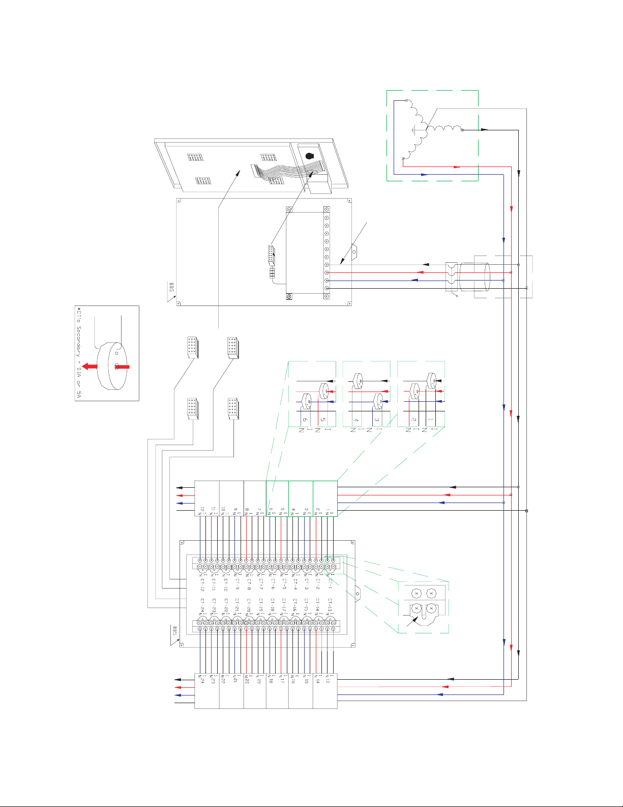
Z Run the current transformer wires black, white/black, red, white/
red and blue, white/blue to terminals CT-1 (I, N), CT-2 (I, N), CT-3 (I,
N), etc. on the MCI board (see the following figure).
The shorting links MUST remain in place while wiring the CTs to the MCI board. Failure
to do could result in severe injury and equipment damage.
Shorting links MUST BE in
place when wiring CT leads
to the MCI board.
White wire connects to "I" terminal
Colored wire connects to "N" terminal
709715A1.CDR
FIGURE 2–6: Wiring of the MCI Board
Z Take the black, red, blue and white (if available) #12 AWG feeder
phase tap wires and run them to VA, VB, VC and N (if available)
respectively (see the following figure).
2–16 EPM 4500 SUB METER – INSTRUCTION MANUAL
Page 31

CHAPTER 2: INSTALLATION INSTALLATION OF METER, MCI BOARD, AND CTS
709716A1.CDR
FIGURE 2–7: Internal Fuse Block
Z Plug the fuse block into the meter head and hang the meter head
on the back box.
EPM 4500 SUB METER – INSTRUCTION MANUAL 2–17
Page 32

INSTALLING THE SCAN TRANSPONDER CHAPTER 2: INSTALLATION
2.4 Installing the Scan Transponder
2.4.1 Procedure
If your application is for a metering system, use the following procedure to install
the scan transponder.
Z Plan for the transponders.
• Determine the number of services in order to determine the
number of transponders.
• Do not rely solely on the memory of the local engineers or of the
existing drawings.
Drawings may not have been properly updated to reflect as-built
conditions and memories are not always accurate. Use these as
guidelines and then perform a survey.
• Open electrical cabinets as necessary and locate every master
meter from the utility.
• Make careful note of the voltages of the various transponders.
Z Determine the number of tenant spaces.
• In residential applications, this number should be fixed.
Often apartments are laid out on a grid, such as by floor and by
line. In this case, the number of meters is simply the number of
floors times the number of lines. This information is needed
before any meters are installed or entered into the transponders.
• Determine which service feeds each metering point. This
information is vital to proper system operation.
Without this information, a laborious process of trial and error is
necessary to determine which transponder must be used for
each meter. This will increase the cost of certification and
commissioning of the system.
Z Determine the service size and type of meter for each metering
point.
• In residential applications, this is probably a constant amperage
across the entire job (either 50 A or 100 A with Series 10 meters).
Z Determine the number of telephone lines required and ensure
the lines are installed before the installation of any metering
equipment.
Z Determine the number of independent services.
• Typically there is one service per distribution transformer that
feeds the property, unless distribution transformers have parallel
secondaries, which is rare.
Z Determine the best location for each transponder.
• This is the closest point to the first point at which the feeders for
the service branch out into sub-feeders.
To find this point, follow the feeders from the secondary of the
distribution transformer (or the service entrance if the
transformer is off the property) and place the transponder at the
last point before the feeder breaks into multiple feeders.
2–18 EPM 4500 SUB METER – INSTRUCTION MANUAL
Page 33

CHAPTER 2: INSTALLATION INSTALLING THE SCAN TRANSPONDER
Z Determine which of the transponders should have a telephone
modem, and order a telephone line to terminate at that point .
Do not proceed with the installation until the telephone line is
installed.
Z After the telephone line is installed, install the scan transponder
with the modem next to the telephone line.
Install all three phases and the neutral to the transponder (see
Installation of Meter, MCI Board, and CTs on page 2–15 for details).
Z If there is more than one transponder, install the other
transponders and the interconnecting RS485 line, if required, which
links all of the transponders (go directly to Installation of Meter, MCI
Board, and CTs on page 2–15 if there is only one transponder in the
system or if each transponder in the system has a modem and
telephone line connection).
• An RS485 line is a pair of wires, AWG #20 or larger in diameter,
which begins at one transponder where a terminator is placed.
• The RS485 line runs from transponder to transponder ending at
the final transponder, where another terminator is placed.
•It is critically important that there should never be three RS485
pairs entering or leaving a transponder box.
• For the two transponders which have terminators, only one
RS485 pair leaves each box.
• For the other transponders, if there are more than two, exactly
two RS485 lines should leave the box: each line goes to another
transponder in the daisy-chain.
Only one modem should be installed in a data link system. If there
are two or more modems in a data link system, the transponders
will not communicate with each other.
• There may be no more than 32 transponders on a daisy-chain.
If there are more than 32, special care must be taken, which is
beyond the scope of these instructions.
Z If possible, run the RS485 lines in a conduit to protect them from
damage.
Z It is critically important to observe the polarity of the wires. The
RS485 data link uses a black and yellow color code. Match black to
black and yellow to yellow; otherwise the data link will not work.
Z To test the data link, measure the DC voltage across the yellow to
black wire.
This should measure between 0.1 and 0.3 V. If it is negative or
outside of that range, re-check all of the transponder boxes
according to the above specifications.
EPM 4500 SUB METER – INSTRUCTION MANUAL 2–19
Page 34

INSTALLING THE SCAN TRANSPONDER CHAPTER 2: INSTALLATION
2–20 EPM 4500 SUB METER – INSTRUCTION MANUAL
Page 35

GE Energy
Industrial Solutions
709710A1.CDR
Using the Meter
3.1 Menu Navigation
EPM4500 Sub Meter
Chapter 3: Using the Meter
3.1.1 User Interface
The following figure shows the EPM4500 user interface located on the front panel of the
meter. It is easy to navigate the various sub-menus to read metering data, reset values and
view configuration data.
Press and hold the “Display Scroll” button. After two seconds, the LCD will display the
REVERSE message. Two seconds later, the LCD will display FORWARD. Two seconds later,
a different sub-menu register heading as shown on the following page (the top row) in will
be displayed in two-second intervals. Note that the EPM4500 defaults to the kWh register.
709719A1.CDR
FIGURE 3–1: EPM4500 User Interface
EPM 4500 SUB METER – INSTRUCTION MANUAL 3–1
Page 36

MENU NAVIGATION CHAPTER 3: USING THE METER
Releasing the display scroll button at a given submenu heading will allow you to cycle
through the registers listed under the selected submenu heading. Pressing and releasing
the display button will advance to the next block of registers in the sub-menu.
To reverse scrolling direction at either the heading level or within a submenu, press and
hold the display scroll button. When
REVERSE is displayed after two seconds, release the
display scroll button. You can now go backwards through the menu selections by pressing
and releasing the display scroll button.
To go back to the forward scrolling option, follow the same procedure, except release the
display scroll button when
FORWARD is displayed.
3–2 EPM 4500 SUB METER – INSTRUCTION MANUAL
Page 37

CHAPTER 3: USING THE METER MENU NAVIGATION
Figure 3–2: EPM4500 Display Structure
EPM 4500 SUB METER – INSTRUCTION MANUAL 3–3
Page 38

CT MULTIPLIER TABLE CHAPTER 3: USING THE METER
3.2 CT Multiplier Table
3.2.1 CT Multipliers
Note
The following table MUST BE used to verify the correct current readings, based on the
rating of the CT installed.
Table 3–1: CT Multiplier Tables
For “L” or 0.1 A models For “H” or 5 A models
CT Size Multiplier CT Size Multiplier
50 A × 0.5 200 A × 40
100 A × 1 400 A × 80
200 A × 2
400 A × 4
800 A × 8
Note
The multiplier that corresponds with the CT rating MUST BE applied to the current reading
shown on the display of the EPM4500 by multiplying that reading by the multiplier shown
above. The multiplier MUST also be applied in the same manner when calculating kW and
kWh. Fai
lure to use the appropriate multiplier wil
l result in an incorrect diagnosis of the
meter's functionality and incorrect revenue billing.
3–4 EPM 4500 SUB METER – INSTRUCTION MANUAL
Page 39

CHAPTER 3: USING THE METER VERIFYING METER FUNCTIONALITY
3.3 Verifying Meter Functionality
3.3.1 Overview
Once you have familiarized yourself with the EPM4500 menu structure, it is critical to verify
that the meter and CTs are properly installed.
Note
To correctly diagnose the meter, there must be loads on all three phases of the meter.
3.3.2 Verifying Voltage
Z Press and hold the Display Scroll button until the following menu
heading is displayed:
Phase Diagnostic
Registers
Z Release the Display Scroll button.
• Scroll down by pressing and releasing the Display Scroll Button
until one of the following sub-menus are displayed (examples
shown for 120 V, 277 V, and 347 V, respectively):
Volts 125.3 A
124.0 B 124.7 C
Volts 348.5 A
347.1 B 347.7 C
Z Verify that phases A, B and C are displaying voltages; i.e., for a
120 V AC, the reading should be 117 V +10%/–15%.
Volts 276.3 A
277.0 B 277.7 C
3.3.3 Verifying kWh Reading
Z Press and hold the Display Scroll button until the following menu
heading is displayed:
kW
Registers
Z Release the Display Scroll button. Scroll down by pressing and
releasing the Display Scroll button until the following sub-menu is
displayed:
AllHrs kWH
1.046 M# 1
Z Verify that the kWh value increases as you view the LCD.
Z To view screens for Meters 2 to 8 (M#2 to M#8), repeat the above
steps.
EPM 4500 SUB METER – INSTRUCTION MANUAL 3–5
Page 40

VERIFYING METER FUNCTIONALITY CHAPTER 3: USING THE METER
3.3.4 Verifying Current and Energy
Z Press and hold the Display Scroll button until the following menu
heading is displayed:
Phase Diagnostic
Registers
Z Release the Display Scroll button.
Scroll down by pressing and releasing the Display Scroll button
until the following submenu is displayed:
Phase 1 7.468 A
818.7 W 100.5 R
The A(mperage) reading in the display above will always be a positive number, even if the
CT was incorrectly installed. Check the reading to see if it indicates the approximate
expected current. Remember that this applies to Phase 1 only. If all the numbers on the
multiplier screen were 1.00 and the current transformers are 100:0.1, your multiplier is 1
and the readings are the actual values. If the CTs are 200:0.1, multiply the current reading
by 2.
The W(att) reading will also count forward as your view the LCD. A negative power reading
is indicative of an incorrectly installed CT, or one that is cross-phased with the wrong
voltage (phase) leg. The R(eactive) reading can be negative, depending on the nature of the
load. Negative values indicate a capacitive load while positive values indicate an inductive
load.
Z Scroll down by pressing and releasing the Display Scroll Button
until the following submenu is displayed:
Ph 1 935.4 VA
6.8° .875 PF
Under normal conditions the phase angle (x.x°) should be close to 0° and the power factor
should be a number close to 1. Resistive loads will have a power factor close to 1, while
inductive loads will typically reflect a power factor between 0.80 to 0.95, or even lower.
If the phase angle on the lower left is a number close to 180°, it indicates the CT was
installed backwards, or 180° out-of-phase. If the number is close to 120°, at least two CTs
have been cross-phased, and a similar number will appear in the phase angle data in
Phase 2.
Note
To view screens for Phases 2 to 24, repeat above steps.
3–6 EPM 4500 SUB METER – INSTRUCTION MANUAL
Page 41

CHAPTER 3: USING THE METER RESETTING THE DEMAND VALUES
3.4 Resetting the Demand Values
3.4.1 Procedure
Use the following procedure to reset the Demand registers to zero:
Z Press and hold the Demand Reset button.
• The LCD will initially display the
• The LCD will then display the
Dmdreset 1
20:00 06/14/2003
Z Keep the Demand Reset button depressed until the screen updates
and displays the current date and time.
This signifies that the demand has been reset.
GE Copyright message.
Dmdreset event screen:
EPM 4500 SUB METER – INSTRUCTION MANUAL 3–7
Page 42

RESETTING THE DEMAND VALUES CHAPTER 3: USING THE METER
3–8 EPM 4500 SUB METER – INSTRUCTION MANUAL
Page 43

GE Energy
Industrial Solutions
EPM4500 Sub Meter
Chapter 4: Communications
709710A1.CDR
Communications
4.1 Modbus Communications
4.1.1 RS485 Wiring for Modbus
The wiring for Modbus communications for two-wire and four-wire RS485 is indicated
below.
For two-wire RS-485:
Color Function DB-9 Pinout
Yellow RX (+) 2
Black TX (–) 8
For four-wire RS-485:
Color Function DB-9 Pinout
Yellow (A) RX (+) 2
Black (B) RX (–) 3
Green (Y) TX (+) 7
Red (Z) TX (–) 8
EPM 4500 SUB METER – INSTRUCTION MANUAL 4–1
Page 44

MODBUS COMMUNICATIONS CHAPTER 4: COMMUNICATIONS
709725A1.CDR
FIGURE 4–1: RS-485 Serial Connections
Note
The EPM4500 optical port is disabled for units with 2-wire RS485 connections.
4.1.2 RS232 Wiring for Modbus
The wiring for Modbus communications for RS232 is indicated below.
Color Function DB-9 Pinout
Black TX 2
Red RX 3
Green GND 5
4.1.3 Modbus Commands
The EPM4500 is capable of acting as a remote slave unit to a Modbus master device via
modem, RS232, RS485, or PLC. Up to 32 EPM4500 meters (or other RS485 devices) can be
daisy-chained together on a single LAN.
The EPM4500 communicates at a default baud rate of 19200, with no parity and 1 stop bit.
The default Modbus address is 100. Changes to the default baud rate or address can be
accomplished through the configuration file upload.
The following Modbus commands are supported by the EPM4500:
• 03: Read R4 type register(s)
• 06: Write single register; address “0” is used as the broadcast address
• 16: Write multiple registers; address “0” is used as the broadcast address
4.1.4 Fixed Modbus Values
The EPM4500 provides fixed register values indicating the meter's serial number, the
meter's version number, and the Modbus addresses.
4–2 EPM 4500 SUB METER – INSTRUCTION MANUAL
Page 45

CHAPTER 4: COMMUNICATIONS MODBUS COMMUNICATIONS
4.1.5 Modbus Data Register (R4 Type) Groups
The EPM4500 has divided the supported register map (see following pages) into the
following register groups for various fixed and dynamic data values:
•Setup Information
•Interval
• Average Interval Data
• Instantaneous Data
• Three-Phase Data
•Real Time Data
• Meter Configuration Data
The EPM4500 provides access to stored-interval data channels via Modbus command. The
data items as defined in the following register map are based on default data channels
that include the following 3-phase-totaled values (interval average) per meter:
• Real Power in kW
• Reactive Power in kvar
• Apparent Power in kVA
• Power Factor
Data is logged per the configurable time interval value. The default log interval is 15
minutes.
The Modbus master can request stored interval data by writing the interval date and time
to the appropriate registers and by setting the data status register to 1. Upon the data
ready flag (address 67) being written to 1, the interval data registers (addresses 100 to 107)
are simultaneously updated with the appropriate values for the requested interval. The
data ready flag returns a 0 for “data is ready”, or “2” for “invalid time interval requested.”
The EPM4500 also provides registers that constantly hold the oldest stored-interval
(addresses 58 to 60) and most recent stored-interval time a
to 63).
4.1.6 Instantaneous Data Items
The EPM4500 provides registers for per-phase instantaneous values (see below).
Instantaneous register values are updated once per second.
•Frequency
• Total Harmonic Distortion (% for volts)
• Voltage
• Current
• Real Power in kW
• Reactive Power in kvar
• Apparent Power in kVA
nd date stamps (addr
esses 61
The EPM4500 provides one-second updated inputs, including the following 3-phasetotaled values per 3-phase-meter:
• Energy: kWh and kvarh
EPM 4500 SUB METER – INSTRUCTION MANUAL 4–3
Page 46

MODBUS COMMUNICATIONS CHAPTER 4: COMMUNICATIONS
• Power: kW, kvar, and kVA
• Power Factor
4.1.7 32-bit Long and Float Data Formats
The EPM4500 supports standard format for 32-bit Long (signed or unsigned). The first of
the two 16-bit Modbus register set contains the HIGH order 16 bits of the 32-bit Long data.
The second of the two 16-bit Modbus register set contains the LOW order 16 bits of the 32bit Long data.
The EPM4500 supports Intel 32 bit (IEEE) FLOAT format. That means, unlike the standard
Long format, the first of the two 16-bit Modbus register set contains the LOW order 16 bits
of the 32-bit Float data. The second of the two 16-bit Modbus register set contains the
HIGH order 16 bits of the 32-bit Float data.
4–4 EPM 4500 SUB METER – INSTRUCTION MANUAL
Page 47

CHAPTER 4: COMMUNICATIONS MODBUS ACTIVATION
4.2 Modbus Activation
4.2.1 Overview
The EPM4500 is shipped with Modbus not activated. To activate the Modbus protocol, it is
necessary to use the Hilgraeve HyperTerminal Private Edition software. This software is
available from the following website:
http://www.hilgraeve.com/htpe
Once Modbus is activated, the meter will ignore the following ASCII commands unless the
login string is sent using the “Key Macros” function within HyperTerminal. Set up “Key
Macros” to send the login string (see Logging into the Meter on page 4–6) followed by
[ENTER].
Note
IMPORTANT: The log in string must be sent without breaking up packets. A direct
connection from a serial port to the EPM4500 RS485 port (via RS232/485 converter) is
highly recommended. GE's Ethernet Gateway will break up this login string into packets
and prevent login.
The EPM4500 only allows login at 9600, 19200 or 38400 baud when NOT in Modbus mode.
This is displayed as HUNT in the meter display under Serial # Registers. Once in Modbus,
the EPM4500 only responds at the programmed baud rate.
4.2.2 Configuring a New HyperTerminal Session
Use the following procedure to configure a new HyperTerminal session.
Z Enter the New Connection Name.
Z Select the COM port to connect to the meter.
Z Select the COM port properties. The following window will appear.
Use the setting shown below.
EPM 4500 SUB METER – INSTRUCTION MANUAL 4–5
Page 48

MODBUS ACTIVATION CHAPTER 4: COMMUNICATIONS
Z Select the File > Properties > Settings > ASCII Setup menu item.
Check the Echo typed characters locally option, as shown below.
4.2.3 Confirming Connection to the EPM4500
To confirm a proper RS485 connection to the EPM4500, enter the following command:
attn -D (followed by the [ENTER] key)
If meter is properly connected, it will respond with a serial number and poll address. Once
in Modbus mode, this command will no longer work.
For example, entering the command
attn -D
followed by the [ENTER] key returns:
60005866 256
for a meter with serial number 60005866 and poll address 256.
4.2.4 Logging into the Meter
Use the following procedure to login to the EPM4500.
Z Setup a ‘key macro’ in HyperTerminal by selecting the View > Key
Macros menu item.
Z Click New and select an appropriate macro key sequence (ALT-1 is
used the example below.
Z Enter the following command in the Action area:
attn -S[serialNumber] -5lEvElbAl<ENTER>
Z The password is -s5 followed by the LABLEVEL text spelled
backwards, with the vowels in upper case.
This login string must be followed by the ENTER command within
the key macro.
For example, for a unit with serial number 60005866, enter the following text:
4–6 EPM 4500 SUB METER – INSTRUCTION MANUAL
Page 49

CHAPTER 4: COMMUNICATIONS MODBUS ACTIVATION
4.2.5 Activating Modbus Communications
Use the following procedure to activate Modbus communications.
Z Enter the following command to activate Modbus:
stty -M1 (followed by [ENTER] twice)
Z Select the baud rate by entering the following command.
The baud rate options for Modbus communication are 9600, 19200,
and 38400.
stty 19200 (followed by [ENTER] twice)
Z Save Modbus activation by entering:
stty -W1234
Z Display Modbus activation by entering:
stty
Z This command displays meter port setting, baud rate, etc.
If Modbus is active, it returns “Modbus”; if Modbus is not active, it
returns “no Modbus”.
For example, consider the following set of commands sets the activates Modbus, sets the
baud rate to 19200, and saves the Modbus activation. The text returned by the meter is
also indicated.
CIP#stty
hunt 19200 baud 8 bits no parity no echo no modem no modbus
CIP#stty -M1
CIP#stty 19200
CIP#stty -W1234
CIP#stty
hold 19200 baud 8 bits no parity no echo no modem modbus
EPM 4500 SUB METER – INSTRUCTION MANUAL 4–7
Page 50

MODBUS ACTIVATION CHAPTER 4: COMMUNICATIONS
4.2.6 Changing Modbus Settings
Use the following procedure to change the Modbus address setting:
Z Enter the following command to set the Modbus address:
attn -p#
where
# is replaced by the actual address desired (for example,
attn -p100).
Z Save the Modbus address as follows
attn -W1234
Z Enter the following command to display and verify the Modbus
address:
attn -d
This command displays the meter serial number and the poll/Modbus
number.
4.2.7 Logging Out
Z Use one of the following commands to logout of the meter:
attn or exit
Note
Once Modbus is set, it is best to type [HALT] followed by [ENTER] or cycle power to the
meter. Otherwise, Modbus will become active one minute after logout.
To log into meter once Modbus is active, use hot keys to program the login sequence. The
login sequence must include either the serial number or the Modbus address.
Example hot key sequences are shown below:
attn -S60005866 -3Super3
attn 256 -3Super3
4.2.8 Disabling Modbus Communications
Use the following procedure to disable Modbus communications:
Z Turn off Modbus with the following command:
stty -M0
Z Save Modbus settings:
stty -W1234
4–8 EPM 4500 SUB METER – INSTRUCTION MANUAL
Page 51

CHAPTER 4: COMMUNICATIONS MODBUS MEMORY MAP
4.3 Modbus Memory Map
4.3.1 Memory Map
The Modbus memory map is shown below.
Table 4–1: Modbus Memory Map (Sheet 1 of 15)
Hex
Addr
0000
0002
0004
0006
0008 0008 Meter Modbus Address R --- 8-bit Modbus Address in LSB
0009 0009 Baud Rate R
000C 0012 Meter Status R --- Always 1 for Modbus.
000D 0013 Meter Ready R --- Always 1 for Modbus.
000E 0014 Number of Meters Conf igured R --- Always 1 for EPM4500
000F 0015 Number of Real-Time Points Configured R
0010 0016 Number of Interval Points Configured R Returns 0 if intervals are disabled
0011 0017 Number of Max/Min Points Configured R Always returns 0
0012 0018 Maximum Number of Intervals That Can Be Recorded R
0013 0019 Number of slots configured for Scan Transponder R
0014 0020 Current slot being read in Scan Transponder W
Addr Description R/W Units Notes
Fixed Value Registers (Read Only)
+
0000 Meter Serial Number R hex digits
+
0002 Meter Serial Number Extension R hex digits Returns same value as address 0000
+
0004 Meter Version Number R hex digits
+
0006 Meter Version Number Extension R hex digits Returns same value as address 0000
Setup Information
Dependent upon the number of parameters optioned
and the number of meters returned in address 0015
Interval Setup
0031 0049 Store Interval Length R minutes
Read Clock
0032 0050 Internal Time - Hours/Minutes R hours/minutes
0033 0051 Internal Time - Seconds R seconds
0034 0052 Internal Date - Month/Day R month/day
0035 0053 Interval Date - Year R year
0036 0054 Internal Time - Hours/Minutes W hours/minutes
0037 0055 Internal Time - Seconds W month/day
0038 0056 Internal Date - Month/Day W Year 16-bit Unsigned Integer
0039 0057 Interval Date - Year W 16-bit Unsigned Integer
Interval length in minutes must be evenly divisible into 60
(1, 2, 3, 4, 5, 6, 10, 12, 15, 20, 30, 60)
16-bit, Hours: 0-23 (bitmask = FF00)
Minutes: 0-59 (bitmask = 00FF
16-bit, Hours: 0-23 (bitmask = FF00)
Minutes: 0-59 (bitmask = 00FF
EPM 4500 SUB METER – INSTRUCTION MANUAL 4–9
Page 52

MODBUS MEMORY MAP CHAPTER 4: COMMUNICATIONS
Table 4–1: Modbus Memory Map (Sheet 2 of 15)
Hex
Addr
003A 0058 Date/Time of Oldest Interval - Hours/Minutes R Hours/Minutes
003B 0059 Date/Time of Oldest Interval - Month/Day R Month/Day
003C 0060 Date/Time of Oldest Interval - Year R Year 16-bit Unsigned Integer
003D 0061 Date/T ime of Newest Interval - Hours/Minutes R Hours/Minutes
003E 0062 Date/Time of Newest Interval - Month/Day R Month/Day
003F 0063 Date/Time of Newest Interval - Year R Year 16 Bit Unsigned Integer
0040 0064
0041 0065 Date/Time of Currently Selected Interval - Month/Day RW Month/Day
0042 0066 Date/T ime of Currently Selected Interval - Year RW Year 16 Bit Unsigned Integer
0043 0067 Data Ready Flag RW
Addr Description R/W Units Notes
16-bit, Hours: 0-23 (bitmask = FF00)
Minutes: 0-59 (bitmask = 00FF)
DDE Data is COM Compatible,
Date/Time Numeric
16-bit
Month: 1=Jan., 12=Dec. (bitmask = FF00)
Day: 1-31 (bitmask = 00FF)
DDE Data is COM Compatible,
Date/Time Numeric
16-bit, Hours: 0-23 (bitmask = FF00)
Minutes: 0-59 (bitmask = 00FF)
16-bit
Month: 1=Jan., 12=Dec. (bitmask = FF00)
Day: 1-31 (bitmask = 00FF)
DDE Data is COM Compatible,
Date/Time Numeric
Date/Time of Currently Selected Interval - Hours/
Minutes
Average Interval Data
RW Hours/Minutes
16-bit, Hours: 0-23 (bitmask = FF00)
Minutes: 0-59 (bitmask = 00FF
16-bit
Month: 1=Jan., 12=Dec. (bitmask = FF00)
Day: 1-31 (bitmask = 00FF)
DDE Data is COM Compatible,
Date/Time Numeric
16 Bits: Mask out/ignore Bit 15.
0=Data is ready for read
1=Populate registers with timestamp data
2=Invalid Timestamp Requested
Stored Dynamic Data Ready for Read
0063 0099 Interval Data Qualifying Register R 16-bit Unsigned Integer, 8 = Invalid Interval
*
0064
0066* 0102 Meter #1 Three-Phase Total kvar R kvar Stored Interval 2 for Meter #1
0068* 0104 Meter #1 Three-Phase Total kVA R kVA Stored Interval 3 for Meter #1
006A* 0106 Meter #1 Three-Phase Total Power Factor R % Stored Interval 4 for Meter #1
006C* 0108 Meter #2 Three-Phase Total kW R kW Stored Interval 1 for Meter #2
006E* 0110 Meter #2 Three-Phase Total kvar R kvar Stored Interval 2 for Meter #2
0070* 0112 Meter #2 Three-Phase Total kVA R kVA Stored Interval 3 for Meter #2
0072* 0114 Meter #2 Three-Phase Total Power Factor R % Stored Interval 4 for Meter #2
0074* 0116 Meter #3 Three-Phase Total kW R kW Stored Interval 1 for Meter #3
0076* 0118 Meter #3 Three-Phase Total kvar R kvar Stored Interval 2 for Meter #3
0078* 0120 Meter #3 Three-Phase Total kVA R kVA Stored Interval 3 for Meter #3
007A* 0122 Meter #3 Three-Phase Total Power Factor R % Stored Interval 4 for Meter #3
007C* 0124 Meter #4 Three-Phase Total kW R kW Stored Interval 1 for Meter #4
007E* 0126 Meter #4 Three-Phase Total kvar R kvar Stored Interval 2 for Meter #4
0080* 0128 Meter #4 Three-Phase Total kVA R kVA Stored Interval 3 for Meter #4
0100 Meter #1 Three-Phase Total kW R kW Stored Interval 1 for Meter #1
4–10 EPM 4500 SUB METER – INSTRUCTION MANUAL
Page 53

CHAPTER 4: COMMUNICATIONS MODBUS MEMORY MAP
Table 4–1: Modbus Memory Map (Sheet 3 of 15)
Hex
Addr
0082* 0130 Meter #4 Three-Phase Total Power Factor R % Stored Interval 4 for Meter #4
0084* 0132 Meter #5 Three-Phase Total kW R kW Stored Interval 1 for Meter #5
0086* 0134 Meter #5 Three-Phase Total kvar R kvar Stored Interval 2 for Meter #5
0088* 0136 Meter #5 Three-Phase Total kVA R kVA Stored Interval 3 for Meter #5
008A* 0138 Meter #5 Three-Phase Total Power Factor R % Stored Interval 4 for Meter #5
008C* 0140 Meter #6 Three-Phase Total kW R kW Stored Interval 1 for Meter #6
008E* 0142 Meter #6 Three-Phase Total kvar R kvar Stored Interval 2 for Meter #6
0090* 0144 Meter #6 Three-Phase Total kVA R kVA Stored Interval 3 for Meter #6
0092* 0146 Meter #6 Three-Phase Total Power Factor R % Stored Interval 4 for Meter #6
0094* 0148 Meter #7 Three-Phase Total kW R kW Stored Interval 1 for Meter #7
0096* 0150 Meter #7 Three-Phase Total kvar R kvar Stored Interval 2 for Meter #7
0098* 0152 Meter #7 Three-Phase Total kVA R kVA Stored Interval 3 for Meter #7
009A* 0154 Meter #7 Three-Phase Total Power Factor R % Stored Interval 4 for Meter #7
009C* 0156 Meter #8 Three-Phase Total kW R kW Stored Interval 1 for Meter #8
009E* 0158 Meter #8 Three-Phase Total kvar R kvar Stored Interval 2 for Meter #8
00A0* 0160 Meter #8 Three-Phase Total kVA R kVA Stored Interval 3 for Meter #8
00A2* 0162 Meter #8 Three-Phase Total Power Factor R % Stored Interval 4 for Meter #8
Addr Description R/W Units Notes
00A4* 0164 Meter #9 Two-Phase Total kW R kW Stored Interval 1 for Meter #9
00A6* 0166 Meter #9 Two-Phase Total kvar R kvar Stored Interval 2 for Meter #9
00A8* 0168 Meter #9 Two-Phase Total kVA R kVA Stored Interval 3 for Meter #9
00AA* 0170 Meter #9 Two-Phase Total Power Factor R % Stored Interval 4 for Meter #9
00AC* 0172 Meter #10 Two-Phase Total kW R kW Stored Interval 1 for Meter #10
00AE* 0174 Meter #10 Two-Phase Total kvar R kvar Stored Interval 2 for Meter #10
00B0* 0176 Meter #10 Two-Phase Total kVA R kVA Stored Interval 3 for Meter #10
00B2* 0178 Meter #10 Two-Phase Total Power Factor R % Stored Interval 4 for Meter #10
00B4* 0180 Meter #11 Two-Phase Total kW R kW Stored Interval 1 for Meter #11
00B6* 0182 Meter #11 Two-Phase Total kvar R kvar Stored Interval 2 for Meter #11
00B8* 0184 Meter #11 Two-Phase Total kVA R kVA Stored Interval 3 for Meter #11
00BA* 0186 Meter #11 Two-Phase Total Power Factor R % Stored Interval 4 for Meter #11
00BC* 0188 Meter #12 Two-Phase Total kW R kW Stored Interval 1 for Meter #12
00BE* 0190 Meter #12 Two-Phase Total kvar R kvar Stored Interval 2 for Meter #12
00C0* 0192 Meter #12 Two-Phase Total kVA R kVA Stored Interval 3 for Meter #12
00C2* 0194 Meter #12 Two-Phase Total Power Factor R % Stored Interval 4 for Meter #12
00C4* 0196 Meter #13 Single-Phase Total kW R kW Stored Interval 1 for Meter #13
00C6* 0198 Meter #13 Single-Phase Total kvar R kvar Stored Interval 2 for Meter #13
EPM 4500 SUB METER – INSTRUCTION MANUAL 4–11
Page 54

MODBUS MEMORY MAP CHAPTER 4: COMMUNICATIONS
Table 4–1: Modbus Memory Map (Sheet 4 of 15)
Hex
Addr
00C8* 0200 Meter #13 Single-Phase Total kVA R kVA Stored Interval 3 for Meter #13
00CA* 0202 Meter #13 Single-Phase Total Power Factor R % Stored Interval 4 for Meter #13
00CC* 0204 Meter #14 Single-Phase Total kW R kW Stored Interval 1 for Meter #14
00CE* 0206 Meter #14 Single-Phase Total kvar R kvar Stored Interval 2 for Meter #14
00D0* 0208 Meter #14 Single-Phase Total kVA R kVA Stored Interval 3 for Meter #14
00D2* 0210 Meter #14 Single-Phase Total Power Factor R % Stored Interval 4 for Meter #14
00D4* 0212 Meter #15 Single-Phase Total kW R kW Stored Interval 1 for Meter #15
00D6* 0214 Meter #15 Single-Phase Total kvar R kvar Stored Interval 2 for Meter #15
00D8* 0216 Meter #15 Single-Phase Total kVA R kVA Stored Interval 3 for Meter #15
00DA* 0218 Meter #15 Single-Phase Total Power Factor R % Stored Interval 4 for Meter #15
00DC* 0220 Meter #16 Single-Phase Total kW R kW Stored Interval 1 for Meter #16
00DE* 0222 Meter #16 Single-Phase Total kvar R kvar Stored Interval 2 for Meter #16
00E0* 0224 Meter #16 Single-Phase Total kVA R kVA Stored Interval 3 for Meter #16
00E2* 0226 Meter #16 Single-Phase Total Power Factor R % Stored Interval 4 for Meter #16
00E4* 0228 Meter #17 Single-Phase Total kW R kW Stored Interval 1 for Meter #17
00E6* 0230 Meter #17 Single-Phase Total kvar R kvar Stored Interval 2 for Meter #17
00E8* 0232 Meter #17 Single-Phase Total kVA R kVA Stored Interval 3 for Meter #17
Addr Description R/W Units Notes
00EA* 0234 Meter #17 Single-Phase Total Power Factor R % Stored Interval 4 for Meter #17
00EC* 0236 Meter #18 Single-Phase Total kW R kW Stored Interval 1 for Meter #18
00EE* 0238 Meter #18 Single-Phase Total kvar R kvar Stored Interval 2 for Meter #18
00F0* 0240 Meter #18 Single-Phase Total kVA R kVA Stored Interval 3 for Meter #18
00F2* 0242 Meter #18 Single-Phase Total Power Factor R % Stored Interval 4 for Meter #18
00F4* 0244 Meter #19 Single-Phase Total kW R kW Stored Interval 1 for Meter #19
00F6* 0246 Meter #19 Single-Phase Total kvar R kvar Stored Interval 2 for Meter #19
00F8* 0248 Meter #19 Single-Phase Total kVA R kVA Stored Interval 3 for Meter #19
00FA* 0250 Meter #19 Single-Phase Total Power Factor R % Stored Interval 4 for Meter #19
00FC* 0252 Meter #20 Single-Phase Total kW R kW Stored Interval 1 for Meter #20
00FE* 0254 Meter #20 Single-Phase Total kvar R kvar Stored Interval 2 for Meter #20
0100* 0256 Meter #20 Single-Phase Total kVA R kVA Stored Interval 3 for Meter #20
0102* 0258 Meter #20 Single-Phase Total Power Factor R % Stored Interval 4 for Meter #20
0104* 0260 Meter #21 Single-Phase Total kW R kW Stored Interval 1 for Meter #21
0106* 0262 Meter #21 Single-Phase Total kvar R kvar Stored Interval 2 for Meter #21
0108* 0264 Meter #21 Single-Phase Total kVA R kVA Stored Interval 3 for Meter #21
010A* 0266 Meter #21 Single-Phase Total Power Factor R % Stored Interval 4 for Meter #21
010C* 0268 Meter #22 Single-Phase Total kW R kW Stored Interval 1 for Meter #22
4–12 EPM 4500 SUB METER – INSTRUCTION MANUAL
Page 55

CHAPTER 4: COMMUNICATIONS MODBUS MEMORY MAP
Table 4–1: Modbus Memory Map (Sheet 5 of 15)
Hex
Addr
010E* 0270 Meter #22 Single-Phase Total kvar R kvar Stored Interval 2 for Meter #22
0110* 0272 Meter #22 Single-Phase Total kVA R kVA Stored Interval 3 for Meter #22
0112* 0274 Meter #22 Single-Phase Total Power Factor R % Stored Interval 4 for Meter #22
0114* 0276 Meter #23 Single-Phase Total kW R kW Stored Interval 1 for Meter #23
0116* 0278 Meter #23 Single-Phase Total kvar R kvar Stored Interval 2 for Meter #23
0118* 0280 Meter #23 Single-Phase Total kVA R kVA Stored Interval 3 for Meter #23
011A* 0282 Meter #23 Single-Phase Total Power Factor R % Stored Interval 4 for Meter #23
011C* 0284 Meter #24 Single-Phase Total kW R kW Stored Interval 1 for Meter #24
011E* 0286 Meter #24 Single-Phase Total kvar R kvar Stored Interval 2 for Meter #24
0120* 0288 Meter #24 Single-Phase Total kVA R kVA Stored Interval 3 for Meter #24
0122* 0290 Meter #24 Single-Phase Total Power Factor R % Stored Interval 4 for Meter #24
0162* 0354 Frequency (Phase A) R Hz Phase-to-Ground Instantaneous Frequency
016A* 0362 Voltage (A-N) R V Phase-to-Ground Instantaneous Voltage
016C* 0364 Voltage (B-N) R V Phase-to-Ground Instantaneous Voltage
016E* 0366 Voltage (C-N) R V Phase-to-Ground Instantaneous Voltage
0170* 0368 Voltage (CT01) R V CT #1 Instantaneous Voltage
Addr Description R/W Units Notes
Metered Values (Instantaneous Data)
0172* 0370 Amps (CT01) R A CT #1 Instantaneous Current
0174* 0372 kW (CT01) R kW CT #1 Instantaneous Power
0176* 0374 kvar (CT01) R kvar CT #1 Instantaneous Reactive Power
0178* 0376 kVA (CT01) R kVA CT #1 Instantaneous Apparent Power
017A* 0378 Voltage (CT02) R V CT #2 Instantaneous Voltage
017C* 0380 Amps (CT02) R A CT #2 Instantaneous Current
017E* 0382 kW (CT02) R kW CT #2 Instantaneous Power
0180* 0384 kvar (CT02) R kvar CT #2 Instantaneous Reactive Power
0182* 0386 kVA (CT02) R kVA CT #2 Instantaneous Apparent Power
0184* 0388 Voltage (CT03) R V CT #3 Instantaneous Voltage
0186* 0390 Amps (CT03) R A CT #3 Instantaneous Current
0188* 0392 kW (CT03) R kW CT #3 Instantaneous Power
018A* 0394 kvar (CT03) R kvar CT #3 Instantaneous Reactive Power
018C* 0396 kVA (CT03) R kVA CT #3 Instantaneous Apparent Power
018E* 0398 Voltage (CT04) R V CT #4 Instantaneous Voltage
0190* 0400 Amps (CT04) R A CT #4 Instantaneous Current
0192* 0402 kW (CT04) R kW CT #4 Instantaneous Power
0194* 0404 kvar (CT04) R kvar CT #4 Instantaneous Reactive Power
EPM 4500 SUB METER – INSTRUCTION MANUAL 4–13
Page 56

MODBUS MEMORY MAP CHAPTER 4: COMMUNICATIONS
Table 4–1: Modbus Memory Map (Sheet 6 of 15)
Hex
Addr
0196* 0406 kVA (CT04) R kVA CT #4 Instantaneous Apparent Power
0198* 0408 Voltage (CT05) R V CT #5 Instantaneous Voltage
019A* 0410 Amps (CT05) R A CT #5 Instantaneous Current
019C* 0412 kW (CT05) R kW CT #5 Instantaneous Power
019E* 0414 kvar (CT05) R kvar CT #5 Instantaneous Reactive Power
01A0* 0416 kVA (CT05) R kVA CT #5 Instantaneous Apparent Power
01A2* 0418 Voltage (CT06) R V CT #6 Instantaneous Voltage
01A4* 0420 Amps (CT06) R A CT #6 Instantaneous Current
01A6* 0422 kW (CT06) R kW CT #6 Instantaneous Power
01A8* 0424 kvar (CT06) R kvar CT #6 Instantaneous Reactive Power
01AA* 0426 kVA (CT06) R kVA CT #6 Instantaneous Apparent Power
01AC* 0428 Voltage (CT07) R V CT #7 Instantaneous Voltage
01AE* 0430 Amps (CT07) R A CT #7 Instantaneous Current
01B0* 0432 kW (CT07) R kW CT #7 Instantaneous Power
01B2* 0434 kvar (CT07) R kvar CT #7 Instantaneous Reactive Power
01B4* 0436 kVA (CT07) R kVA CT #7 Instantaneous Apparent Power
01B6* 0438 Voltage (CT08) R V CT #8 Instantaneous Voltage
Addr Description R/W Units Notes
01B8* 0440 Amps (CT08) R A CT #8 Instantaneous Current
01BA* 0442 kW (CT08) R kW CT #8 Instantaneous Power
01BC* 0444 kvar (CT08) R kvar CT #8 Instantaneous Reactive Power
01BE* 0446 kVA (CT08) R kVA CT #8 Instantaneous Apparent Power
01C0* 0448 Voltage (CT09) R V CT #9 Instantaneous Voltage
01C2* 0450 Amps (CT09) R A CT #9 Instantaneous Current
01C4* 0452 kW (CT09) R kW CT #9 Instantaneous Power
01C6* 0454 kvar (CT09) R kvar CT #9 Instantaneous Reactive Power
01C8* 0456 kVA (CT09) R kVA CT #9 Instantaneous Apparent Power
01CA* 0458 Voltage (CT10) R V CT #10 Instantaneous Voltage
01CC* 0460 Amps (CT10) R A CT #10 Instantaneous Current
01CE* 0462 kW (CT10) R kW CT #10 Instantaneous Power
01D0* 0464 kvar (CT10) R kvar CT #10 Instantaneous Reactive Power
01D2* 0466 kVA (CT10) R kVA CT #10 Instantaneous Apparent Power
01D4* 0468 Voltage (CT11) R V CT #11 Instantaneous Voltage
01D6* 0470 Amps (CT11) R A CT #11 Instantaneous Current
01D8* 0472 kW (CT11) R kW CT #11 Instantaneous Power
01DA* 0474 kvar (CT11) R kvar CT #11 Instantaneous Reactive Power
4–14 EPM 4500 SUB METER – INSTRUCTION MANUAL
Page 57

CHAPTER 4: COMMUNICATIONS MODBUS MEMORY MAP
Table 4–1: Modbus Memory Map (Sheet 7 of 15)
Hex
Addr
01DC* 0476 kVA (CT11) R kVA CT #11 Instantaneous Apparent Power
01DE* 0478 Voltage (CT12) R V CT #12 Instantaneous Voltage
01E0* 0480 Amps (CT12) R A CT #12 Instantaneous Current
01E2* 0482 kW (CT12) R kW CT #12 Instantaneous Power
01E4* 0484 kvar (CT12) R kvar CT #12 Instantaneous Reactive Power
01E6* 0486 kVA (CT12) R kVA CT #12 Instantaneous Apparent Power
01E8* 0488 Voltage (CT13) R V CT #13 Instantaneous Voltage
01EA* 0490 Amps (CT13) R A CT #13 Instantaneous Current
01EC* 0492 kW (CT13) R kW CT #13 Instantaneous Power
01EE* 0494 kvar (CT13) R kvar CT #13 Instantaneous Reactive Power
01F0* 0496 kVA (CT13) R kVA CT #13 Instantaneous Apparent Power
01F2* 0498 Voltage (CT14) R V CT #14 Instantaneous Voltage
01F4* 0500 Amps (CT14) R A CT #14 Instantaneous Current
01F6* 0502 kW (CT14) R kW CT #14 Instantaneous Power
01F8* 0504 kvar (CT14) R kvar CT #14 Instantaneous Reactive Power
01FA* 0506 kVA (CT14) R kVA CT #14 Instantaneous Apparent Power
01FC* 0508 Voltage (CT15) R V CT #15 Instantaneous Voltage
Addr Description R/W Units Notes
01FE* 0510 Amps (CT15) R A CT #15 Instantaneous Current
200* 0512 kW (CT15) R kW CT #15 Instantaneous Power
0202* 0514 kvar (CT15) R kvar CT #15 Instantaneous Reactive Power
0204* 0516 kVA (CT15) R kVA CT #15 Instantaneous Apparent Power
0206* 0518 Voltage (CT16) R V CT #16 Instantaneous Voltage
0208* 0520 Amps (CT16) R A CT #16 Instantaneous Current
020A* 0522 kW (CT16) R kW CT #16 Instantaneous Power
020C* 0524 kvar (CT16) R kvar CT #16 Instantaneous Reactive Power
020E* 0526 kVA (CT16) R kVA CT #16 Instantaneous Apparent Power
0210* 0528 Voltage (CT17) R V CT #17 Instantaneous Voltage
0212* 0530 Amps (CT17) R A CT #17 Instantaneous Current
0214* 0532 kW (CT17) R kW CT #17 Instantaneous Power
0216* 0534 kvar (CT17) R kvar CT #17 Instantaneous Reactive Power
0218* 0536 kVA (CT17) R kVA CT #17 Instantaneous Apparent Power
021A* 0538 Voltage (CT18) R V CT #18 Instantaneous Voltage
021C* 0540 Amps (CT18) R A CT #18 Instantaneous Current
021E* 0542 kW (CT18) R kW CT #18 Instantaneous Power
0220* 0544 kvar (CT18) R kvar CT #18 Instantaneous Reactive Power
EPM 4500 SUB METER – INSTRUCTION MANUAL 4–15
Page 58

MODBUS MEMORY MAP CHAPTER 4: COMMUNICATIONS
Table 4–1: Modbus Memory Map (Sheet 8 of 15)
Hex
Addr
0222* 0546 kVA (CT18) R kVA CT #18 Instantaneous Apparent Power
0224* 0548 Voltage (CT19) R V CT #19 Instantaneous Voltage
0226* 0550 Amps (CT19) R A CT #19 Instantaneous Current
0228* 0552 kW (CT19) R kW CT #19 Instantaneous Power
022A* 0554 kvar (CT19) R kvar CT #19 Instantaneous Reactive Power
022C* 0556 kVA (CT19) R kVA CT #19 Instantaneous Apparent Power
022E* 0558 Voltage (CT20) R V CT #20 Instantaneous Voltage
0230* 0560 Amps (CT20) R A CT #20 Instantaneous Current
0232* 0562 kW (CT20) R kW CT #20 Instantaneous Power
0234* 0564 kvar (CT20) R kvar CT #20 Instantaneous Reactive Power
0236* 0566 kVA (CT20) R kVA CT #20 Instantaneous Apparent Power
0238* 0568 Voltage (CT21) R V CT #21 Instantaneous Voltage
023A* 0570 Amps (CT21) R A CT #21 Instantaneous Current
023C* 0572 kW (CT21) R kW CT #21 Instantaneous Power
023E* 0574 kvar (CT21) R kvar CT #21 Instantaneous Reactive Power
0240* 0576 kVA (CT21) R kVA CT #21 Instantaneous Apparent Power
0242* 0578 Voltage (CT22) R V CT #22 Instantaneous Voltage
Addr Description R/W Units Notes
0244* 0580 Amps (CT22) R A CT #22 Instantaneous Current
0246* 0582 kW (CT22) R kW CT #22 Instantaneous Power
0248* 0584 kvar (CT22) R kvar CT #22 Instantaneous Reactive Power
024A* 0586 kVA (CT22) R kVA CT #22 Instantaneous Apparent Power
024C* 0588 Voltage (CT23) R V CT #23 Instantaneous Voltage
024E* 0590 Amps (CT23) R A CT #23 Instantaneous Current
0250* 0592 kW (CT23) R kW CT #23 Instantaneous Power
0252* 0594 kvar (CT23) R kvar CT #23 Instantaneous Reactive Power
0254* 0596 kVA (CT23) R kVA CT #23 Instantaneous Apparent Power
0256* 0598 Voltage (CT24) R V CT #24 Instantaneous Voltage
0258* 0600 Amps (CT24) R A CT #24 Instantaneous Current
025A* 0602 kW (CT24) R kW CT #24 Instantaneous Power
025C* 0604 kvar (CT24) R kvar CT #24 Instantaneous Reactive Power
025E* 0606 kVA (CT24) R kVA CT #24 Instantaneous Apparent Power
4–16 EPM 4500 SUB METER – INSTRUCTION MANUAL
Page 59

CHAPTER 4: COMMUNICATIONS MODBUS MEMORY MAP
Table 4–1: Modbus Memory Map (Sheet 9 of 15)
Hex
Addr
0288* 0648 Meter #1 Three-Phase kWh R kWh Meter #1 Real Time Input 1
028A* 0650 Meter #1 Three-Phase kvarh R kvarh Meter #1 Real Time Input 2
028C* 0652 Meter #1 Three-Phase kW R kW Meter #1 Real Time Input 3
028E* 0654 Meter #1 Three-Phase kvar R kvar Meter #1 Real Time Input 4
0290* 0656 Meter #1 Three-Phase kVA R kVA Meter #1 Real T ime Input 5
0292* 0658 Meter #1 Three-Phase Power Factor R % Meter #1 Real T ime Input 6
0294* 0660 Meter #2 Three-Phase kWh R kWh Meter #2 Real Time Input 1
0296* 0662 Meter #2 Three-Phase kvarh R kvarh Meter #2 Real Time Input 2
0298* 0664 Meter #2 Three-Phase kW R kW Meter #2 Real Time Input 3
029A* 0666 Meter #2 Three-Phase kvar R kvar Meter #2 Real Time Input 4
029C* 0668 Meter #2 Three-Phase kVA R kVA Meter #2 Real Time Input 5
029E* 0670 Meter #2 Three-Phase Power Factor R % Meter #2 Real T ime Input 6
02A0* 0672 Meter #3 Three-Phase kWh R kWh Meter #3 Real T ime Input 1
02A2* 0674 Meter #3 Three-Phase kvarh R kvarh Meter #3 Real Time Input 2
02A4 0676 Meter #3 Three-Phase kW R kW Meter #3 Real T ime Input 3
02A6* 0678 Meter #3 Three-Phase kvar R kvar Meter #3 Real Time Input 4
Addr Description R/W Units Notes
Three-Phase Metered Values (Fast Poll)
02A8* 0680 Meter #3 Three-Phase kVA R kVA Meter #3 Real Time Input 5
02AA* 0682 Meter #3 Three-Phase Power Factor R % Meter #3 Real Time Input 6
02AC* 0684 Meter #4 Three-Phase kWh R kWh Meter #4 Real T ime Input 1
02AE* 0686 Meter #4 Three-Phase kvarh R kvarh Meter #4 Real T ime Input 2
02B0* 0688 Meter #4 Three-Phase kW R kW Meter #4 Real Time Input 3
02B2* 0690 Meter #4 Three-Phase kvar R kvar Meter #4 Real Time Input 4
02B4* 0692 Meter #4 Three-Phase kVA R kVA Meter #4 Real Time Input 5
02B6* 0694 Meter #4 Three-Phase Power Factor R % Meter #4 Real Time Input 6
02B8* 0696 Meter #5 Three-Phase kWh R kWh Meter #5 Real T ime Input 1
02BA* 0698 Meter #5 Three-Phase kvarh R kvarh Meter #5 Real Time Input 2
02BC* 0700 Meter #5 Three-Phase kW R kW Meter #5 Real Time Input 3
02BE* 0702 Meter #5 Three-Phase kvar R kvar Meter #5 Real T ime Input 4
02C0* 0704 Meter #5 Three-Phase kVA R kVA Meter #5 Real Time Input 5
02C2* 0706 Meter #5 Three-Phase Power Factor R % Meter #5 Real Time Input 6
02C4 0708 Meter #6 Three-Phase kWh R kWh Meter #6 Real Time Input 1
02C6* 0710 Meter #6 Three-Phase kvarh R kvarh Meter #6 Real Time Input 2
02C8* 0712 Meter #6 Three-Phase kW R kW Meter #6 Real Time Input 3
02CA* 0714 Meter #6 Three-Phase kvar R kvar Meter #6 Real T ime Input 4
EPM 4500 SUB METER – INSTRUCTION MANUAL 4–17
Page 60

MODBUS MEMORY MAP CHAPTER 4: COMMUNICATIONS
Table 4–1: Modbus Memory Map (Sheet 10 of 15)
Hex
Addr
02CC* 0716 Meter #6 Three-Phase kVA R kVA Meter #6 Real Time Input 5
02CE* 0718 Meter #6 Three-Phase Power Factor R % Meter #6 Real Time Input 6
02D0* 0720 Meter #7 Three-Phase kWh R kWh Meter #7 Real Time Input 1
02D2* 0722 Meter #7 Three-Phase kvarh R kvarh Meter #7 Real Time Input 2
02D4* 0724 Meter #7 Three-Phase kW R kW Meter #7 Real T ime Input 3
02D6* 0726 Meter #7 Three-Phase kvar R kvar Meter #7 Real Time Input 4
02D8 0728 Meter #7 Three-Phase kVA R kVA Meter #7 Real Time Input 5
02DA* 0730 Meter #7 Three-Phase Power Factor R % Meter #7 Real Time Input 6
02DC* 0732 Meter #8 Three-Phase kWh R kWh Meter #8 Real Time Input 1
02DE* 0734 Meter #8 Three-Phase kvarh R kvarh Meter #8 Real Time Input 2
02E0* 0736 Meter #8 Three-Phase kW R kW Meter #8 Real Time Input 3
02E2* 0738 Meter #8 Three-Phase kvar R kvar Meter #8 Real Time Input 4
02E4* 0740 Meter #8 Three-Phase kVA R kVA Meter #8 Real Time Input 5
02E6* 0742 Meter #8 Three-Phase Power Factor R % Meter #8 Real T ime Input 6
02E8* 0744 Meter #9 Phase kWh R kWh Meter #9 Real Time Input 1
02EA* 0746 Meter #9 Phase kvarh R kvarh Meter #9 Real Time Input 2
02EC* 0748 Meter #9 Phase kW R kW Meter #9 Real T ime Input 3
Addr Description R/W Units Notes
02EE* 0750 Meter #9 Phase kvar R kvar Meter #9 Real T ime Input 4
02F0* 0752 Meter #9 Phase kVA R kVA Meter #9 Real Time Input 5
02F2* 0754 Meter #9 Phase Power Factor R % Meter #9 Real Time Input 6
02F4* 0756 Meter #10 Phase kWh R kWh Meter #10 Real Time Input 1
02F6* 0758 Meter #10 Phase kvarh R kvarh Meter #10 Real Time Input 2
02F8* 0760 Meter #10 Phase kW R kW Meter #10 Real Time Input 3
02FA* 0762 Meter #10 Phase kvar R kvar Meter #10 Real T ime Input 4
02FC* 0764 Meter #10 Phase kVA R kVA Meter #10 Real Time Input 5
02FE* 0766 Meter #10 Phase Power Factor R % Meter #10 Real Time Input 6
0300* 0768 Meter #11 Phase kWh R kWh Meter #11 Real Time Input 1
0302* 0770 Meter #11 Phase kvarh R kvarh Meter #11 Real Time Input 2
0304* 0772 Meter #11 Phase kW R kW Meter #11 Real Time Input 3
0306* 0774 Meter #11 Phase kvar R kvar Meter #11 Real Time Input 4
0308* 0776 Meter #11 Phase kVA R kVA Meter #11 Real Time Input 5
030A* 0778 Meter #11 Phase Power Factor R % Meter #11 Real T ime Input 6
030C* 0780 Meter #12 Phase kWh R kWh Meter #12 Real T ime Input 1
030E* 0782 Meter #12 Phase kvarh R kvarh Meter #12 Real Time Input 2
0310* 0784 Meter #12 Phase kW R kW Meter #12 Real Time Input 3
4–18 EPM 4500 SUB METER – INSTRUCTION MANUAL
Page 61

CHAPTER 4: COMMUNICATIONS MODBUS MEMORY MAP
Table 4–1: Modbus Memory Map (Sheet 11 of 15)
Hex
Addr
0312* 0786 Meter #12 Phase kvar R kvar Meter #12 Real Time Input 4
0314* 0788 Meter #12 Phase kVA R kVA Meter #12 Real Time Input 5
0316* 0790 Meter #12 Phase Power Factor R % Meter #12 Real Time Input 6
0318* 0792 Meter #13 Phase kWh R kWh Meter #13 Real Time Input 1
031A* 0794 Meter #13 Phase kvarh R kvarh Meter #13 Real Time Input 2
031C* 0796 Meter #13 Phase kW R kW Meter #13 Real T ime Input 3
031E* 0798 Meter #13 Phase kvar R kvar Meter #13 Real T ime Input 4
0320* 0800 Meter #13 Phase kVA R kVA Meter #13 Real Time Input 5
0322* 0802 Meter #13 Phase Power Factor R % Meter #13 Real Time Input 6
0324* 0804 Meter #14 Phase kWh R kWh Meter #14 Real Time Input 1
0326* 0806 Meter #14 Phase kvarh R kvarh Meter #14 Real Time Input 2
0328* 0808 Meter #14 Phase kW R kW Meter #14 Real Time Input 3
032A* 0810 Meter #14 Phase kvar R kvar Meter #14 Real Time Input 4
032C* 0812 Meter #14 Phase kVA R kVA Meter #14 Real T ime Input 5
032E* 0814 Meter #14 Phase Power Factor R % Meter #14 Real Time Input 6
0330* 0816 Meter #15 Phase kWh R kWh Meter #15 Real Time Input 1
0332* 0818 Meter #15 Phase kvarh R kvarh Meter #15 Real Time Input 2
Addr Description R/W Units Notes
0334* 0820 Meter #15 Phase kW R kW Meter #15 Real Time Input 3
0336* 0822 Meter #15 Phase kvar R kvar Meter #15 Real Time Input 4
0338* 0824 Meter #15 Phase kVA R kVA Meter #15 Real Time Input 5
033A* 0826 Meter #15 Phase Power Factor R % Meter #15 Real T ime Input 6
033C* 0828 Meter #16 Phase kWh R kWh Meter #16 Real Time Input 1
033E* 0830 Meter #16 Phase kvarh R kvarh Meter #16 Real Time Input 2
0340* 0832 Meter #16 Phase kW R kW Meter #16 Real Time Input 3
0342* 0834 Meter #16 Phase kvar R kvar Meter #16 Real Time Input 4
0344* 0836 Meter #16 Phase kVA R kVA Meter #16 Real Time Input 5
0346* 0838 Meter #16 Phase Power Factor R % Meter #16 Real Time Input 6
0348* 0840 Meter #17 Phase kWh R kWh Meter #17 Real Time Input 1
034A* 0842 Meter #17 Phase kvarh R kvarh Meter #17 Real Time Input 2
034C* 0844 Meter #17 Phase kW R kW Meter #17 Real T ime Input 3
034E* 0846 Meter #17 Phase kvar R kvar Meter #17 Real T ime Input 4
0350* 0848 Meter #17 Phase kVA R kVA Meter #17 Real Time Input 5
0352* 0850 Meter #17 Phase Power Factor R % Meter #17 Real Time Input 6
0354* 0852 Meter #18 Phase kWh R kWh Meter #18 Real Time Input 1
0356* 0854 Meter #18 Phase kvarh R kvarh Meter #18 Real Time Input 2
EPM 4500 SUB METER – INSTRUCTION MANUAL 4–19
Page 62

MODBUS MEMORY MAP CHAPTER 4: COMMUNICATIONS
Table 4–1: Modbus Memory Map (Sheet 12 of 15)
Hex
Addr
0358* 0856 Meter #18 Phase kW R kW Meter #18 Real Time Input 3
035A* 0858 Meter #18 Phase kvar R kvar Meter #18 Real Time Input 4
035C* 0860 Meter #18 Phase kVA R kVA Meter #18 Real T ime Input 5
035E* 0862 Meter #18 Phase Power Factor R % Meter #18 Real Time Input 6
0360* 0864 Meter #19 Phase kWh R kWh Meter #19 Real Time Input 1
0362* 0866 Meter #19 Phase kvarh R kvarh Meter #19 Real Time Input 2
0364* 0868 Meter #19 Phase kW R kW Meter #19 Real Time Input 3
0366* 0870 Meter #19 Phase kvar R kvar Meter #19 Real Time Input 4
0368* 0872 Meter #19 Phase kVA R kVA Meter #19 Real Time Input 5
036A* 0874 Meter #19 Phase Power Factor R % Meter #19 Real T ime Input 6
036C* 0876 Meter #20 Phase kWh R kWh Meter #20 Real T ime Input 1
036E* 0878 Meter #20 Phase kvarh R kvarh Meter #20 Real Time Input 2
0370* 0880 Meter #20 Phase kW R kW Meter #20 Real Time Input 3
0372* 0882 Meter #20 Phase kvar R kvar Meter #20 Real Time Input 4
0374* 0884 Meter #20 Phase kVA R kVA Meter #20 Real Time Input 5
0376* 0886 Meter #20 Phase Power Factor R % Meter #20 Real Time Input 6
0378* 0888 Meter #21 Phase kWh R kWh Meter #21 Real Time Input 1
Addr Description R/W Units Notes
037A* 0890 Meter #21 Phase kvarh R kvarh Meter #21 Real Time Input 2
037C* 0892 Meter #21 Phase kW R kW Meter #21 Real T ime Input 3
037E* 0894 Meter #21 Phase kvar R kvar Meter #21 Real T ime Input 4
0380* 0896 Meter #21 Phase kVA R kVA Meter #21 Real Time Input 5
0382* 0898 Meter #21 Phase Power Factor R % Meter #21 Real Time Input 6
0384* 0900 Meter #22 Phase kWh R kWh Meter #22 Real Time Input 1
0386* 0902 Meter #22 Phase kvarh R kvarh Meter #22 Real Time Input 2
0388* 0904 Meter #22 Phase kW R kW Meter #22 Real Time Input 3
038A* 0906 Meter #22 Phase kvar R kvar Meter #22 Real Time Input 4
038C* 0908 Meter #22 Phase kVA R kVA Meter #22 Real T ime Input 5
038E* 0910 Meter #22 Phase Power Factor R % Meter #22 Real Time Input 6
0390* 0912 Meter #23 Phase kWh R kWh Meter #23 Real Time Input 1
0392* 0914 Meter #23 Phase kvarh R kvarh Meter #23 Real Time Input 2
0394* 0916 Meter #23 Phase kW R kW Meter #23 Real Time Input 3
0396* 0918 Meter #23 Phase kvar R kvar Meter #23 Real Time Input 4
0398* 0920 Meter #23 Phase kVA R kVA Meter #23 Real Time Input 5
039A* 0922 Meter #23 Phase Power Factor R % Meter #23 Real T ime Input 6
039C* 0924 Meter #24 Phase kWh R kWh Meter #24 Real T ime Input 1
4–20 EPM 4500 SUB METER – INSTRUCTION MANUAL
Page 63

CHAPTER 4: COMMUNICATIONS MODBUS MEMORY MAP
Table 4–1: Modbus Memory Map (Sheet 13 of 15)
Hex
Addr
039E* 0926 Meter #24 Phase kvarh R kvarh Meter #24 Real Time Input 2
03A0* 0928 Meter #24 Phase kW R kW Meter #24 Real Time Input 3
03A2* 0930 Meter #24 Phase kvar R kvar Meter #24 Real Time Input 4
03A4* 0932 Meter #24 Phase kVA R kVA Meter #24 Real Time Input 5
03A6* 0934 Meter #24 Phase Power Factor R % Meter #24 Real Time Input 6
03E8* 1000 Meter #1 THD Phase A R % Meter #1 Total Harmonic Distortion
03EA* 1002 Meter #1 Phase Angle A R degrees Meter #1 Phase Angle
03EC* 1004 Meter #1 Phase-to-Phase Voltage A R V Meter #1 Instantaneous Voltage
03EE* 1006 Meter #1 THD Phase B R % Meter #1 Total Harmonic Distortion
03F0* 1008 Meter #1 Phase Angle B R degrees Meter #1 Phase Angle
03F2* 1010 Meter #1 Phase-to-Phase Voltage B R V Meter #1 Instantaneous Voltage
03F4* 1012 Meter #1 THD Phase C R % Meter #1 Total Harmonic Distortion
03F6* 1014 Meter #1 Phase Angle C R degrees Meter #1 Phase Angle
03F8* 1016 Meter #1 Phase-to-Phase Voltage C R V Meter #1 Instantaneous Voltage
03FA* 1018 Meter #2 THD Phase A R % Meter #2 Total Harmonic Distortion
03FC* 1020 Meter #2 Phase Angle A R degrees Meter #2 Phase Angle
Addr Description R/W Units Notes
Real Time Data
03FE* 1022 Meter #2 Phase-to-Phase Voltage A R V Meter #2 Instantaneous Voltage
0400* 1024 Meter #2 THD Phase B R % Meter #2 Total Harmonic Distortion
0402* 1026 Meter #2 Phase Angle B R degrees Meter #2 Phase Angle
0404* 1028 Meter #2 Phase-to-Phase Voltage B R V Meter #2 Instantaneous Voltage
0406* 1030 Meter #2 THD Phase C R % Meter #2 Total Harmonic Distortion
0408* 1032 Meter #2 Phase Angle C R degrees Meter #2 Phase Angle
040A* 1034 Meter #2 Phase-to-Phase Voltage C R V Meter #2 Instantaneous Voltage
040C* 1036 Meter #3 THD Phase A R % Meter #3 Total Harmonic Distortion
040E* 1038 Meter #3 Phase Angle A R degrees Meter #3 Phase Angle
0410* 1040 Meter #3 Phase-to-Phase Voltage A R V Meter #3 Instantaneous Voltage
0412* 1042 Meter #3 THD Phase B R % Meter #3 Total Harmonic Distortion
0414* 1044 Meter #3 Phase Angle B R degrees Meter #3 Phase Angle
0416* 1046 Meter #3 Phase-to-Phase Voltage B R V Meter #3 Instantaneous Voltage
0418* 1048 Meter #3 THD Phase C R % Meter #3 Total Harmonic Distortion
041A* 1050 Meter #3 Phase Angle C R degrees Meter #3 Phase Angle
041C* 1052 Meter #3 Phase-to-Phase Voltage C R V Meter #3 Instantaneous Voltage
041E* 1054 Meter #4 THD Phase A R % Meter #4 Total Harmonic Distortion
0420* 1056 Meter #4 Phase Angle A R degrees Meter #4 Phase Angle
EPM 4500 SUB METER – INSTRUCTION MANUAL 4–21
Page 64

MODBUS MEMORY MAP CHAPTER 4: COMMUNICATIONS
Table 4–1: Modbus Memory Map (Sheet 14 of 15)
Hex
Addr
0422* 1058 Meter #4 Phase-to-Phase Voltage A R V Meter #4 Instantaneous Voltage
0424* 1060 Meter #4 THD Phase B R % Meter #4 Total Harmonic Distortion
0426* 1062 Meter #4 Phase Angle B R degrees Meter #4 Phase Angle
0428* 1064 Meter #4 Phase-to-Phase Voltage B R V Meter #4 Instantaneous Voltage
042A* 1066 Meter #4 THD Phase C R % Meter #4 Total Harmonic Distortion
042C* 1068 Meter #4 Phase Angle C R degrees Meter #4 Phase Angle
042E* 1070 Meter #4 Phase-to-Phase Voltage C R V Meter #4 Instantaneous Voltage
0430* 1072 Meter #5 THD Phase A R % Meter #5 Total Harmonic Distortion
0432* 1074 Meter #5 Phase Angle A R degrees Meter #5 Phase Angle
0434* 1076 Meter #5 Phase-to-Phase Voltage A R V Meter #5 Instantaneous Voltage
0436* 1078 Meter #5 THD Phase B R % Meter #5 Total Harmonic Distortion
0438* 1080 Meter #5 Phase Angle B R degrees Meter #5 Phase Angle
043A* 1082 Meter #5 Phase-to-Phase Voltage B R V Meter #5 Instantaneous Voltage
043C* 1084 Meter #5 THD Phase C R % Meter #5 Total Harmonic Distortion
043E* 1086 Meter #5 Phase Angle C R degrees Meter #5 Phase Angle
0440* 1088 Meter #5 Phase-to-Phase Voltage C R V Meter #5 Instantaneous Voltage
0442* 1090 Meter #6 THD Phase A R % Meter #6 Total Harmonic Distortion
Addr Description R/W Units Notes
0444* 1092 Meter #6 Phase Angle A R degrees Meter #6 Phase Angle
0446* 1094 Meter #6 Phase-to-Phase Voltage A R V Meter #6 Instantaneous Voltage
0448 1096 Meter #6 THD Phase B R % Meter #6 Total Harmonic Distortion
044A* 1098 Meter #6 Phase Angle B R degrees Meter #6 Phase Angle
044C* 1100 Meter #6 Phase-to-Phase Voltage B R V Meter #6 Instantaneous Voltage
044E* 1102 Meter #6 THD Phase C R % Meter #6 Total Harmonic Distortion
0450* 1104 Meter #6 Phase Angle C R degrees Meter #6 Phase Angle
0452* 1106 Meter #6 Phase-to-Phase Voltage C R V Meter #6 Instantaneous Voltage
0454* 1108 Meter #7 THD Phase A R % Meter #7 Total Harmonic Distortion
0456* 1110 Meter #7 Phase Angle A R degrees Meter #7 Phase Angle
0458* 1112 Meter #7 Phase-to-Phase Voltage A R V Meter #7 Instantaneous Voltage
045A* 1114 Meter #7 THD Phase B R % Meter #7 Total Harmonic Distortion
045C* 1116 Meter #7 Phase Angle B R degrees Meter #7 Phase Angle
045E* 1118 Meter #7 Phase-to-Phase Voltage B R V Meter #7 Instantaneous Voltage
0460* 1120 Meter #7 THD Phase C R % Meter #7 Total Harmonic Distortion
0462* 1122 Meter #7 Phase Angle C R degrees Meter #7 Phase Angle
0464* 1124 Meter #7 Phase-to-Phase Voltage C R V Meter #7 Instantaneous Voltage
0466* 1126 Meter #8 THD Phase A R % Meter #8 Total Harmonic Distortion
4–22 EPM 4500 SUB METER – INSTRUCTION MANUAL
Page 65

CHAPTER 4: COMMUNICATIONS MODBUS MEMORY MAP
Table 4–1: Modbus Memory Map (Sheet 15 of 15)
Hex
Addr
0468* 1128 Meter #8 Phase Angle A R degrees Meter #8 Phase Angle
046A* 1130 Meter #8 Phase-to-Phase Voltage A R V Meter #8 Instantaneous Voltage
046C* 1132 Meter #8 THD Phase B R % Meter #8 Total Harmonic Distortion
046E* 1134 Meter #8 Phase Angle B R degrees Meter #8 Phase Angle
0470* 1136 Meter #8 Phase-to-Phase Voltage B R V Meter #8 Instantaneous Voltage
0472* 1138 Meter #8 THD Phase C R % Meter #8 Total Harmonic Distortion
0474* 1140 Meter #8 Phase Angle C R degrees Meter #8 Phase Angle
0476* 1142 Meter #8 Phase-to-Phase Voltage C R V Meter #8 Instantaneous Voltage
07D0 2000 Number of phases offset R
07D1 2001 Demand Window Offset R
07D2 2002 I Multiplier Type Offset R
07D3 2003 Number of Pulse Counters Offset R
07D4 2004 Overlap Offset R
Addr Description R/W Units Notes
Counters
16-bit Unsigned Integer
1, 2, 3, or 24 phases available
16-bit Unsigned Integer
5, 15, or 30 minutes available
16-bit Unsigned Integer
Internal calibration value
16-bit Unsigned Integer
Number of external pulse inputs installed
16-bit Unsigned Integer
Number of adjacent demand windows that are averaged
to determine peak demand
07D5 2005 Number TOU's Offset R
07D6 2006 MDT_M_TABLE_REG_START R 16-bit Unsigned Integer
07D7 2007 NUM_MDT_M_TABLE_COLUMNS R 16-bit Unsigned Integer
07D8 2008 NUM_MDT_M_TABLE_REGS R 16-bit Unsigned Integer
07D9 2009 MDT_M_TABLE_REG_END R 16-bit Unsigned Integer
16-bit Unsigned Integer
Number of different TOU periods defined in the time-ofuse table
* 32-bit floating point register.
+
32-bit long integer - Range: 00000000h to FFFFFFFFh
Note
1. 32-bit floating point numbers are as per the IEEE 754-1985 standard.
2. Registers 0X0063 to 0X025E are all read-only and cannot be modified. They break
down as follows:
• Registers 0X0064 to 0X0122 are not real-time, but are populated with
stored interval data based on user inputs to registers 0X0040 to 0X0043.
• Registers 0X0162 to 0X025E are all real-time data registers.
EPM 4500 SUB METER – INSTRUCTION MANUAL 4–23
Page 66

MODBUS MEMORY MAP CHAPTER 4: COMMUNICATIONS
4–24 EPM 4500 SUB METER – INSTRUCTION MANUAL
Page 67

GE Energy
Industrial Solutions
709710A1.CDR
Miscellaneous
5.1 Revision History
EPM4500 Sub Meter
Chapter 5: Miscellaneous
5.1.1 Release Dates
GEK-106555 1601-0157-A1 1.0x 10 June 2004
GEK-106555A 1601-0157-A2 1.0x 18 October 2004
GEK-106555B 1601-0157-A3 1.0x 1 December 2004
GEK-106555C 1601-0157-A4 1.0x 5 January 2005
GEK-106555D 1601-0157-A5 1.0x 14 February 2005
GEK-106555E 1601-0157-A6 1.0x 08 April 2005
GEK-106555F 1601-0157-A7 1.0x 20 February 2006
GEK-106555G 1601-0157-A8 1.0x 30 June 2006
GEK-106555H 1601-0157-A9 1.0x 22 November 2007
Table 5–1: Release Dates
MANUAL GE PART NO. EPM4500
REVISION
RELEASE DATE
EPM 4500 SUB METER – INSTRUCTION MANUAL 5–1
Page 68

REVISION HISTORY CHAPTER 5: MISCELLANEOUS
5.1.2 Changes to the Manual
Table 5–2: Major Updates for 1601-0157-A9
PAGE
(A8)
PAGE
(A9)
CHANGE DESCRIPTION
Title Title Update Manual part number to 1601-0157-A9
4-9 4-9 Update
Modbus Memory Map - inserted hex addresses and
notes.
Table 5–3: Major Updates for 1601-0157-A8
PAGE
(A7)
PAGE
(A8)
CHANGE DESCRIPTION
Title Title Update Manual part number to 1601-0157-A8
4-1 4-1 Update Updated RS485 WIRING FOR MODBUS section
--- 4-2 Add Added RS232 WIRING FOR MODBUS section
Table 5–4: Major Updates for 1601-0157-A7
PAGE
(A6)
PAGE
(A7)
CHANGE DESCRIPTION
Title Title Update Manual part number to 1601-0157-A7
3-2 3-2 Update Updated EPM4500 DISPLAY STRUCTURE diagram
Table 5–5: Major Updates for 1601-0157-A6
PAGE
(A5)
PAGE
(A6)
CHANGE DESCRIPTION
Title Title Update Manual part number to 1601-0157-A6
4-3 4-3 Update Updated MODBUS ACTIVATION section
Table 5–6: Major Updates for 1601-0157-A5
PAGE
(A4)
PAGE
(A5)
CHANGE DESCRIPTION
Title Title Update Manual part number to 1601-0157-A5
--- 4-1 Add Added RS485 WIRING FOR MODBUS section
5–2 EPM 4500 SUB METER – INSTRUCTION MANUAL
Page 69

CHAPTER 5: MISCELLANEOUS REVISION HISTORY
Table 5–7: Major Updates for 1601-0157-A4
PAGE
(A3)
PAGE
(A4)
CHANGE DESCRIPTION
Title Title Update Manual part number to 1601-0157-A4
4-6 4-6 Update
Updated MODBUS MEMORY MAP to include
additional registers
Table 5–8: Major Updates for 1601-0157-A3
PAGE
(A2)
PAGE
(A3)
CHANGE DESCRIPTION
Title Title Update Manual part number to 1601-0157-A3
4-3 4-3 Update Updated MODBUS ACTIVATION section
Table 5–9: Major Updates for 1601-0157-A2
PAGE
(A1)
PAGE
(A2)
CHANGE DESCRIPTION
Title Title Update Manual part number to 1601-0157-A2
--- 2-2 Replace
updated PHASE ASSOCIATION section. Phase rotation
information is now included with the wiring types.
Replaced PHASE ROTATION section and example with
--- 2-4 Replace
Updated the WIRING section to include new wiring
diagrams and wiring procedures
--- 4-1 Add Added MODBUS COMMUNICATIONS chapter
EPM 4500 SUB METER – INSTRUCTION MANUAL 5–3
Page 70

WARRANTY CHAPTER 5: MISCELLANEOUS
5.2 Warranty
5.2.1 GE Energy Warranty
General Electric Energy (GE Energy) warrants each device it manufactures to be free from
defects in material and workmanship under normal use and service for a period of 24
months from date of shipment from factory.
In the event of a failure covered by warranty, GE Energy will undertake to repair or replace
the device providing the warrantor determined that it is defective and it is returned with all
transportation charges prepaid to an authorized service centre or the factory. Repairs or
replacement under warranty will be made without charge.
Warranty shall not apply to any device which has been subject to misuse, negligence,
accident, incorrect installation or use not in accordance with instructions nor any unit that
has been altered outside a GE Energy authorized factory outlet.
GE Energy is not liable for special, indirect or consequential damages or for loss of profit or
for expenses sustained as a result of a device malfunction, incorrect application or
adjustment.
For complete text of Warranty (including limitations and disclaimers), refer to GE Energy
Standard Conditions of Sale.
5–4 EPM 4500 SUB METER – INSTRUCTION MANUAL
Page 71

Index
A
ANSI APPROVAL......................................................................................................................................................1–7
APPLICATIONS.........................................................................................................................................................1–2
C
CATALOG NUMBERS.............................................................................................................................................1–8
CHANGES TO MANUAL..............................................................................................................................5–2, 5–3
COMMERCIAL METER...........................................................................................................................................1–8
COMMUNICATIONS
activating Modbus communications.................................................................................................4–7
memory map ................................................................................................................................................4–9
Modbus............................................................................................................................................................4–2
Modbus data groups.................................................................................................................................4–3
CT INSTALLATION ............................................................................................................................................... 2–15
CT MULTIPLIERS .....................................................................................................................................................3–4
CT ORDER CODES ..................................................................................................................................................1–9
CURRENT TRANSFORMER INSTALLATION................................................................................................2–15
CURRENT, VERIFYING...........................................................................................................................................3–6
D
DATA LOGGER.........................................................................................................................................................1–5
DEMAND, RESETTING...........................................................................................................................................3–7
DEMAND, SPECIFICATIONS................................................................................................................................1–5
DIMENSIONS............................................................................................................................................................1–6
DISPLAY STRUCTURE............................................................................................................................................3–3
E
ENERGY, VERIFYING..............................................................................................................................................3–6
ENVIRONMENTAL SPECIFICATIONS...............................................................................................................1–6
G
GETTING STARTED.................................................................................................................................................1–1
I
INSTALLATION CATEGORY.................................................................................................................................1–6
INTERIOR VIEW .......................................................................................................................................................1–3
INTERNAL FUSE BLOCK.................................................................................................................................... 2–17
M
MCI BOARD, WIRING .........................................................................................................................................2–16
MENU NAVIGATION ..............................................................................................................................................3–1
MENU STRUCTURE................................................................................................................................................3–3
METERING SYSTEM................................................................................................................................................1–2
EPM 4500 SUB METER – INSTRUCTION MANUAL INDEX–1
Page 72

INDEX
METERING SYSTEM REQUIREMENTS.............................................................................................................2–1
METERING, SPECIFICATIONS.............................................................................................................................1–5
MODBUS
activating........................................................................................................................................................4–7
commands .....................................................................................................................................................4–2
data register groups..................................................................................................................................4–3
memory map ................................................................................................................................................4–9
wiring................................................................................................................................................................4–2
O
OPTIONS ....................................................................................................................................................................1–8
ORDER CODES.........................................................................................................................................................1–8
P
POLLUTION DEGREE.............................................................................................................................................1–6
POWER SUPPLY ......................................................................................................................................................1–5
PREVENTIVE MAINTENANCE.............................................................................................................................1–4
PROTECTIVE CONDUCTOR TERMINAL..........................................................................................................1–4
PROTOCOLS..............................................................................................................................................................1–6
PULSE INPUTS .........................................................................................................................................................1–9
R
RESIDENTIAL METER.............................................................................................................................................1–8
RS232 WIRING FOR MODBUS..........................................................................................................................4–2
RS485 WIRING FOR MODBUS..........................................................................................................................4–1
S
SCAN TRANSPONDER
functionality...................................................................................................................................................1–2
installing.......................................................................................................................................................2–18
location.........................................................................................................................................................2–18
models..............................................................................................................................................................1–9
SHIPPING SPECIFICATIONS................................................................................................................................1–6
SPECIFICATIONS.....................................................................................................................................................1–5
STAND-ALONE METER .........................................................................................................................................1–2
T
TRANSIENT/SURGE SUPRESSION....................................................................................................................1–6
TYPE TESTS................................................................................................................................................................1–6
U
UL APPROVAL..........................................................................................................................................................1–7
USER INTERFACE....................................................................................................................................................3–1
V
VERIFYING CURRENT............................................................................................................................................3–6
VERIFYING ENERGY...............................................................................................................................................3–6
VERIFYING METER FUNCTIONALITY...............................................................................................................3–5
INDEX–2 EPM 4500 SUB METER – INSTRUCTION MANUAL
Page 73

VERIFYING VOLTAGE ............................................................................................................................................3–5
VERTICAL MOUNTING OPTION.........................................................................................................................2–2
VOLTAGE, VERIFYING...........................................................................................................................................3–5
W
WARNINGS ...............................................................................................................................................................1–3
WARRANTY...............................................................................................................................................................5–4
WIRING
1-phase, 3-wire.............................................................................................................................2–12, 2–14
1-phase, 3-wire 120 V..................................................................................................................... 2–6, 2–8
3-phase, 3-wire delta................................................................................................................... 2–9, 2–11
3-phase, 4-wire wye........................................................................................................................2–3, 2–5
overview..........................................................................................................................................................2–2
EPM 4500 SUB METER – INSTRUCTION MANUAL INDEX–3
Page 74

INDEX
INDEX–4 EPM 4500 SUB METER – INSTRUCTION MANUAL
 Loading...