

Page 1

GE
Entellisys™ Low Voltage Switchgear
Device Replacement Guide
Page 2

DEH-234
Warnings, Cautions, and Notes as used in this publication
Warnings
WARNING! Warning notices are used in this publication to emphasize that hazardous voltages,
currents, or other conditions that could cause personal injury exist in this equipment or may be
associated with its use.
Warning notices are also used for situations in which inattention or lack of equipment knowledge
could cause either personal injury or damage to equipment.
Cautions
CAUTION: Caution notices are used for situations in which equipment might be damaged if care is
not taken.
Notes
NOTE: Notes call attention to information that is especially significant to understanding and
operating the equipment.
This document is based on information available at the time of its publication. While efforts have been
made to ensure accuracy, the information contained herein does not cover all details or variations in
hardware and software, nor does it provide for every possible contingency in connection with
installation, operation, and maintenance. Features may be described in here that are not present in all
hardware and software systems. GE Consumer & Industrial assumes no obligation of notice to holders
of this document with respect to changes subsequently made.
GE Consumer & Industrial makes no representation or warranty, expressed, implied, or statutory, with
respect to, and assumes no responsibility for the accuracy, completeness, sufficiency, or usefulness of
the information contained herein. No warrantees of merchantability or fitness for purpose shall apply.
Entellisys™, EntelliGuard™, and FlexLogic™ are trademarks of the General Electric Company.
Modbus RTU is a registered trademark of AEG Schneider Automation.
©Copyright 2005 General Electric
All Rights Reserved
Page 3

How to contact us
Please have your Entellisys System Summary # and Sub # ready when calling. This information can be
found on the Entellisys HMI on the System Health screen by clicking the Job Info button.
Post Sales Service
GE Switchgear
510 Agency Road
West Burlington, IA 52655
Phone (toll free): 1-888-437-3765
Additional information:
www.entellisys.com/support
Page 4

Page 5

Contents
1 Replacing a CPU chassis
1.1 Removing the side and horizontal-mount chassis . . . . . . . . . . . . . . . . . . . . . . . . . . . . . . . . . . . . . . . . . . . . . . . . . . . . . . . 7
1.2 Installing the side and horizontal-mount chassis . . . . . . . . . . . . . . . . . . . . . . . . . . . . . . . . . . . . . . . . . . . . . . . . . . . . . . . . 9
1.3 Removing the rear-mount front-most chassis. . . . . . . . . . . . . . . . . . . . . . . . . . . . . . . . . . . . . . . . . . . . . . . . . . . . . . . . . . . 9
1.4 Installing the rear-mount front-most chassis. . . . . . . . . . . . . . . . . . . . . . . . . . . . . . . . . . . . . . . . . . . . . . . . . . . . . . . . . . . 12
1.5 Removing the rear-mount rear-most chassis . . . . . . . . . . . . . . . . . . . . . . . . . . . . . . . . . . . . . . . . . . . . . . . . . . . . . . . . . . 12
1.6 Installing the rear-mount rear-most chassis . . . . . . . . . . . . . . . . . . . . . . . . . . . . . . . . . . . . . . . . . . . . . . . . . . . . . . . . . . . 13
2 Replacing an EntelliGuard™ Messenger
2.1 Removing the Messenger from the switchgear compartment. . . . . . . . . . . . . . . . . . . . . . . . . . . . . . . . . . . . . . . . . . . 15
2.2 Replacing the Messenger faceplate . . . . . . . . . . . . . . . . . . . . . . . . . . . . . . . . . . . . . . . . . . . . . . . . . . . . . . . . . . . . . . . . . . . 18
2.3 Installing the Messenger . . . . . . . . . . . . . . . . . . . . . . . . . . . . . . . . . . . . . . . . . . . . . . . . . . . . . . . . . . . . . . . . . . . . . . . . . . . . . . 19
3 Replacing an HMI
3.1 Removing the HMI: standard compartment door. . . . . . . . . . . . . . . . . . . . . . . . . . . . . . . . . . . . . . . . . . . . . . . . . . . . . . . 21
3.2 Installing the HMI: standard compartment door. . . . . . . . . . . . . . . . . . . . . . . . . . . . . . . . . . . . . . . . . . . . . . . . . . . . . . . . 23
4 Replacing a switch
4.1 Before you begin . . . . . . . . . . . . . . . . . . . . . . . . . . . . . . . . . . . . . . . . . . . . . . . . . . . . . . . . . . . . . . . . . . . . . . . . . . . . . . . . . . . . . 25
4.2 Removing the 8-port and 16-port mounting plate. . . . . . . . . . . . . . . . . . . . . . . . . . . . . . . . . . . . . . . . . . . . . . . . . . . . . . 25
4.3 Installing the 8-port and 16-port mounting plate. . . . . . . . . . . . . . . . . . . . . . . . . . . . . . . . . . . . . . . . . . . . . . . . . . . . . . . 27
4.4 Removing the 8-port and 16-port switches from DIN rail . . . . . . . . . . . . . . . . . . . . . . . . . . . . . . . . . . . . . . . . . . . . . . . 28
4.5 Installing the 8-port and 16-port switches from DIN rail . . . . . . . . . . . . . . . . . . . . . . . . . . . . . . . . . . . . . . . . . . . . . . . . 28
4.6 Removing the 8-port switch from the mounting bracket. . . . . . . . . . . . . . . . . . . . . . . . . . . . . . . . . . . . . . . . . . . . . . . . 29
4.7 Installing the 8-port switch to the mounting bracket . . . . . . . . . . . . . . . . . . . . . . . . . . . . . . . . . . . . . . . . . . . . . . . . . . . 30
4.8 Removing the 24-port switch from the mounting bracket. . . . . . . . . . . . . . . . . . . . . . . . . . . . . . . . . . . . . . . . . . . . . . . 30
4.9 Installing the 24-port switch to the mounting bracket . . . . . . . . . . . . . . . . . . . . . . . . . . . . . . . . . . . . . . . . . . . . . . . . . . 30
5 Replacing a VPN
5.1 Removing the VPN device and bracket . . . . . . . . . . . . . . . . . . . . . . . . . . . . . . . . . . . . . . . . . . . . . . . . . . . . . . . . . . . . . . . . 31
5.2 Installing the VPN and bracket . . . . . . . . . . . . . . . . . . . . . . . . . . . . . . . . . . . . . . . . . . . . . . . . . . . . . . . . . . . . . . . . . . . . . . . . 32
6 Replacing an RS-232 to RS-485 converter
6.1 Removing the RS232/485 converter . . . . . . . . . . . . . . . . . . . . . . . . . . . . . . . . . . . . . . . . . . . . . . . . . . . . . . . . . . . . . . . . . . . 33
6.2 Installing the RS232/485 converter . . . . . . . . . . . . . . . . . . . . . . . . . . . . . . . . . . . . . . . . . . . . . . . . . . . . . . . . . . . . . . . . . . . . 35
7 Replacing a UPS
7.1 Removing the UPS . . . . . . . . . . . . . . . . . . . . . . . . . . . . . . . . . . . . . . . . . . . . . . . . . . . . . . . . . . . . . . . . . . . . . . . . . . . . . . . . . . . . 37
7.2 Installing the UPS. . . . . . . . . . . . . . . . . . . . . . . . . . . . . . . . . . . . . . . . . . . . . . . . . . . . . . . . . . . . . . . . . . . . . . . . . . . . . . . . . . . . . 40
Contents 5
Page 6

6 Contents
Page 7

1 Replacing a CPU chassis
1.1 Removing the side and horizontal-mount chassis
1. Prepare for the shut down of the CPU by setting the remaining CPU in the system as the
default. (On the Main Menu, click User Settings, and then click HMI Preferences.)
WARNING! Voltages hazardous to personnel are present.
2. Open the instrument compartment. On the chassis to be removed, turn the power off using
the switch located at the rear of the chassis. When the chassis is powered off, the CPU
indicators do not light.
Figure 1-1 CPU rear
1
3. On the CPU to be removed, disconnect the two Ethernet cables from ETH0 and ETH1 and one
synch clock cable from PORT 1 or COM 2, making note to which port each is connected.
Figure 1-2 CPU front
4. At the rear of the chassis, remove the 2-pin connector plug by depressing the tab and sliding
the plug out of the socket.
5. Remove the four mounting bolts and star washers at the front of the chassis.
6. Slide the chassis outward 1 to 2 inches.
7. Remove the 120 Vac power cable at the rear of the chassis by pulling it out of its socket.
8. Remove the chassis from the mounting bracket.
WARNING! Voltages hazardous to personnel and equipment are present—be careful not to
contact the energized terminal blocks on the compartment walls.
Removing the side and horizontal-mount chassis 7
Page 8
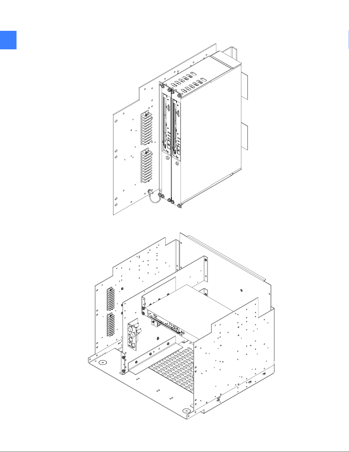
Figure 1-3 Side-mounted chassis
1
Figure 1-4 Horizontally mounted chassis
Replacing a CPU chassis8
Page 9

1.2 Installing the side and horizontal-mount chassis
1. Make sure the power switch at the rear of the chassis is in the OFF position.
2. Locate the 120 Vac power socket and 2-pin 12 Vdc socket at the rear of the chassis.
3. Partially insert the chassis into the mounting bracket.
WARNING! Voltages hazardous to personnel and equipment are present—be careful not to
contact the energized terminal blocks on the compartment walls.
4. Install the 120 Vac power cable by pushing it firmly into the socket.
5. Connect the 2-pin plug by inserting it into the socket until it clicks into place.
6. Slide the chassis into the mounting bracket until the chassis mounting ears contact the
bracket tabs.
7. Install four mounting bolts and star washers into the mounting ears and bracket tabs.
8. Reconnect the two Ethernet cables into the CPU card according to the markings on the cable
ends and as noted in the removal process above.
9. Reconnect the synch clock cable to PORT 0 (CPU A) or to COM 2 (CPU B).
10. Turn on power to the CPU and chassis using the power switch. The indicators at the front of
the CPU should light.
1
11. Close the instrument compartment.
12. When the CPU has completed booting, verify its operation from the HMI's System Health
screen. At this time it may be desired to set the replaced CPU as the system default. (From
the Main Menu, click User Settings, and then click HMI Preferences.)
1.3 Removing the rear-mount front-most chassis
1. Prepare for the shut down of the CPU by setting the remaining CPU in the system as the
default. (From the Main Menu, click User Settings, and then click HMI Preferences.)
WARNING! Voltages hazardous to personnel are present.
2. Open the instrument compartment. Turn off power using the switch at the rear of the frontmost chassis. When the chassis is powered off, the CPU indicators do not light.
3. Disconnect the two Ethernet cables and one synch clock cable from the CPU, making note to
which port each is connected.
4. At the rear of the chassis, remove the 2-pin connector plug by depressing the tab and sliding
the plug out and away from the chassis.
Installing the side and horizontal-mount chassis 9
Page 10
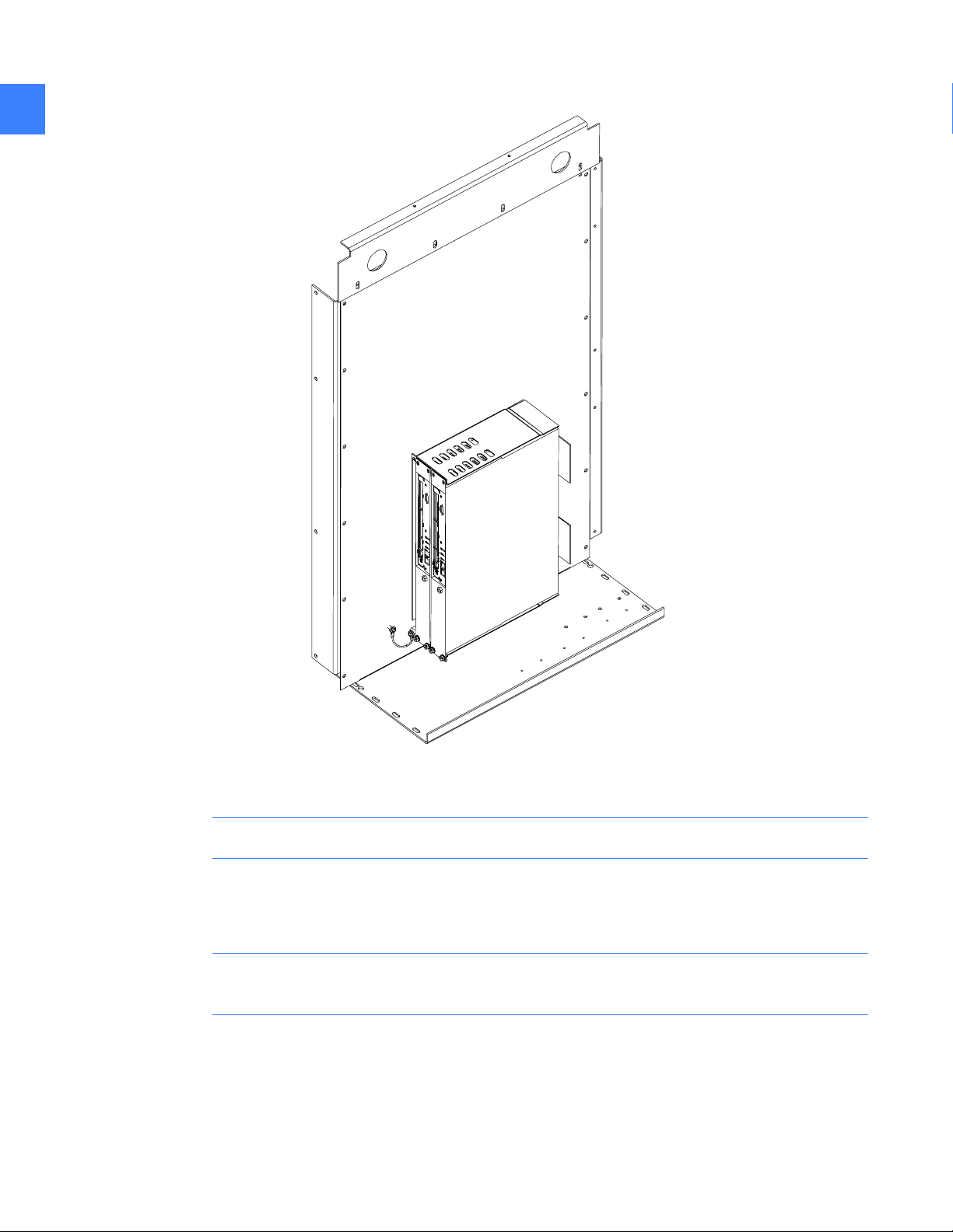
Figure 1-5 Rear-mounted chassis
1
5. Remove the mounting bolts and star washers from the front-most chassis.
NOTE: Do not remove any mounting hardware from the rear chassis.
6. Remove the 120 Vac power cable by pulling it out of its socket.
7. Pull the chassis out of the mounting bracket.
WARNING! Voltages hazardous to personnel and equipment are present—be careful not to
contact the energized terminal blocks on the compartment walls.
Replacing a CPU chassis10
Page 11

Figure 1-6 Rear-mounted chassis, tilted forward
1
Removing the rear-mount front-most chassis 11
Page 12

1
1.4 Installing the rear-mount front-most chassis
1. Make sure that the power switch at the rear of the chassis is in the OFF position.
2. Locate the 120 Vac power socket and the 2-pin 12 Vdc socket at the rear of the chassis.
3. Insert the replacement chassis into the mounting bracket.
NOTE: Do not remove any mounting hardware from the rear chassis.
WARNING! Voltages hazardous to personnel and equipment are present—be careful not to
contact the energized terminal blocks on the compartment walls.
4. Install the 120 Vac power cable by pushing it firmly into the socket.
5. Connect the 2-pin plug by inserting it into the socket until it clicks into place.
6. Install four mounting bolts and star washers into the chassis tab holes. Make sure they are
fully tightened.
7. Re-connect the two Ethernet cables into the CPU card according to the markings on the
cable ends.
8. Reconnect the synch clock cable to PORT 0 (CPU A) or to COM 2 (CPU B).
9. Turn on power to the CPU and chassis using the power switch. The indicators at the front of
the CPU should light.
10. Close the instrument compartment.
When the CPU has completed booting, verify its operation from the HMI's System Health screen.
At this time it may be desired to set the replaced CPU as the system default. (From the Main
Menu, click User Settings, and then click HMI Preferences.)
1.5 Removing the rear-mount rear-most chassis
1. Prepare for the shut down of the CPU by setting the remaining CPU in the system as the
default. (From the Main Menu, click User Settings, and then click HMI Preferences.)
WARNING! Voltages hazardous to personnel are present.
2. Open the instrument compartment. Turn off power using the switch at the rear of the rearmost chassis. When the chassis is powered off, the CPU indicators do not light.
3. Disconnect the two Ethernet cables and one synch clock cable from the CPU, making note to
which port each is connected.
4. At the rear of the chassis, remove the 2-pin connector plug by depressing the tab and sliding
the plug out and away from the chassis.
5. Remove the four mounting bolts and star washers at the tops of both chassis.
Replacing a CPU chassis12
Page 13

6. Tip each chassis outward, pivoting on the hinge at the bottom of the mounting bracket. Do
not allow the wiring to support the chassis.
7. Remove the remaining two mounting bolts and star washers from the rear-most chassis.
8. Remove the 120 Vac power cable by pulling it out of its socket.
9. Pull the rear-most chassis out of the mounting bracket.
WARNING! Voltages hazardous to personnel and equipment are present. Be careful not to
contact the energized terminal blocks on the compartment walls.
1.6 Installing the rear-mount rear-most chassis
1. Make sure that the power switch at the rear of the chassis is in the OFF position.
2. Locate the 120 Vac power socket and the 2-pin 12 Vdc socket at the rear of the chassis.
3. Tip the front-most chassis outward, pivoting on the hinge at the bottom of the mounting
bracket. Do not allow the wiring to support the chassis.
4. Insert the replacement chassis into the mounting bracket.
1
WARNING! Voltages hazardous to personnel and equipment are present—be careful not to
contact the energized terminal blocks on the compartment walls.
5. Install the 120 Vac power cable by pushing it firmly into the socket.
6. Connect the 2-pin plug by inserting it into the socket until it clicks into place.
7. Install two mounting bolts and star washers into the replacement chassis tabs nearest the
bracket hinge.
8. Tip the chassis back into the vertical position. Hold down the cables at the rear of each
chassis to avoid snagging them on the stationary portion of the mounting bracket.
9. Install four mounting bolts and star washers into the chassis tab holes opposite the bracket
hinge. Make sure they are fully tightened.
10. Reconnect the two Ethernet cables into the CPU card according to the markings on the
cable ends.
11. Reconnect the synch clock cable to PORT 0 (CPU A) or to COM 2 (CPU B).
12. Turn on power to the CPU and chassis using the power switch. The indicators at the front of
the CPU should light.
13. Close the instrument compartment.
14. When the CPU has completed booting, verify its operation from the HMI's System Health
screen. At this time it may be desired to set the replaced CPU as the system default. (From
the Main Menu, click User Settings, and then click HMI Preferences.)
Installing the rear-mount rear-most chassis 13
Page 14

1
Replacing a CPU chassis14
Page 15

2 Replacing an EntelliGuard™ Messenger
WARNING! Disconnecting an EntelliGuard Messenger removes overcurrent protection and
centralized control from its associated circuit breaker frame. Other EntelliGuard Messenger and
circuit breaker frames will continue to function normally as long as control power is maintained.
2.1 Removing the Messenger from the switchgear compartment
1. Place the equipment into Reduced Let-Thru Mode by logging into the HMI under an account
with Administrative privilege.
2. On the Main Menu, click the Reduced Let-Thru Mode button.
3. Click the Enable button on the Reduced Let-Thru Mode screen, and then click OK.
4. Ensure the PPE (Personal Protective Equipment) is appropriate for opening and removing a
circuit breaker from the gear.
2
5. Open the circuit breaker (immediately under the Messenger) that you intend to replace.
Check that the circuit breaker flag, Messenger faceplate, and HMI indicate that the circuit
breaker is open.
6. Rack the circuit breaker out to the “Disconnect” position.
NOTE: Closing springs will discharge during the rack out procedure if the circuit breaker is
charged; however, the circuit breaker will remain in the open position.
WARNING! Verify the circuit breaker position indicator and HMI indicate that the circuit
breaker is in the “disconnect” position.
7. Open the compartment door.
8. In compartments for electrically operated circuit breakers, remove the charge motor, close
coil, and shunt trip fuses at the upper left side of the compartment
9. In compartments for circuit breakers with a network interlock accessory, remove the set and
reset fuses at the upper right side of the compartment
10. Under the Messenger and to the right, locate one blue 30-pin plug and one configuration
plug. At the left of the Messenger, locate one blue 12-pin plug and two Ethernet cables (A and
B).
Removing the Messenger from the switchgear compartment 15
Page 16

Figure 2-1 Right-hand underside of Messenger
22
Figure 2-2 Left-hand underside of Messenger
Replacing an EntelliGuard™ Messenger16
Page 17

WARNING! The 30-pin plug contains 120 Vac control power connections. Avoid physical
contact with the connector pins.
11. Disconnect the 30-pin plug by first depressing the side tabs and then pulling the plug out of
the Messenger.
12. Disconnect the configuration plug by first depressing the side tabs and then pulling the
plug out of the Messenger.
13. Note the relative positions of each Ethernet cable. Disconnect the two cables by first
depressing the tab at the top of the connector and then pulling the connector out of the
Messenger.
WARNING! The 12-pin plug can contain 18 Vac PT connections depending on system
configuration. Avoid physical contact with the connector pins.
14. Disconnect the 12-pin plug by first depressing the side tabs and then pulling the plug out of
the Messenger.
15. At the Messenger faceplate, record the Rating and Setting rotary switch positions. These
will be needed to set the replacement unit.
16. At the Messenger faceplate, remove the two round plastic caps to expose the mounting
screws.
2
17. Completely remove the two mounting screws.
18. Using both hands, carefully pull the Messenger out and away from the front of the
switchgear compartment so as not to disturb any wiring and then remove it from the
compartment.
Removing the Messenger from the switchgear compartment 17
Page 18

2.2 Replacing the Messenger faceplate
22
1. Open the clear window on the faceplate by depressing the top-center tab.
Figure 2-3 Faceplate with window opened
2. Completely remove the two screws.
3. Carefully pull the faceplate from the original Messenger.
NOTE: To avoid mismatching the faceplates to their respective compartments, remove only
one Messenger and faceplate from the switchgear at a time.
4. Place the faceplate over the front of the new Messenger housing. Align the two screw holes,
two knobs, and plug opening in the faceplate with the corresponding holes, knobs, and plug
on the Messenger housing.
5. Install the two screws through the faceplate into the Messenger housing. Gently tighten the
two screws.
6. At the Messenger faceplate, set the Rating and Setting rotary switch positions to the
previously recorded value.
7. Close the plastic window.
Replacing an EntelliGuard™ Messenger18
Page 19

2.3 Installing the Messenger
1. Ensure that PPE is appropriate for installing and closing a circuit breaker and that the
equipment is still in Reduced Let-Thru Mode.
2. Open the door of the circuit breaker compartment located immediately below the
Messenger opening.
3. Place the tabs at the sides of the Messenger housing onto the mounting rails in the
compartment.
4. Slide the Messenger into the compartment until the rear of the faceplate has contacted the
switchgear hinge blocks, being careful to not disturb any wiring.
5. Fasten the faceplate to the hinge blocks with the two mounting screws.
6. Replace the two round plastic caps over the mounting screws.
WARNING! The 12-pin plug can contain 18 Vac PT connections depending on system
configuration. Avoid physical contact with the connector pins.
7. Install the 12-pin plug into the corresponding socket at the left of the Messenger. The plug's
side tabs should lock the connector into place and prevent removal.
8. Check for proper installation by gently tugging on the 12-pin plug.
9. Re-connect the two Ethernet cables into the sockets at the left of the Messenger in the same
positions they were originally installed in. The tab of the Ethernet cables should lock the
connectors into place and prevent removal.
2
10. Check for proper installation by gently tugging on each Ethernet cable.
11. Install the configuration plug at the right of the Messenger by inserting the plug housing
into the socket until the side tabs click into place.
12. Check for proper installation by gently tugging on the plug housing.
WARNING! The 30-pin plug contains 120 Vac control power connections. Avoid physical
contact with the connector pins.
13. Install the 30-pin plug into the corresponding socket at the right of the Messenger. The side
tabs should lock the plug into place and prevent removal.
14. Check for proper installation by gently tugging on the 30-pin plug.
15. Check to ensure the Messenger power and communication indicators illuminate.
16. In compartments for circuit breakers with a network interlock device, install the 10A set and
reset fuses in the fuse holders at the upper right of the compartment.
17. In compartments for electrically operated circuit breakers, install the 20A charge motor,
15A close coil, and 10A shunt trip fuses into the fuse holders at the upper left of the
compartment.
18. Check the wire bundles at the sides of the Messenger. The wire bundles should not obstruct
the circuit breaker as it enters or exits the compartment. Any extra wire length may be
gently pushed into the openings in the compartment side sheets.
Installing the Messenger 19
Page 20

19. Close the compartment door.
20. On the HMI's System Health and Breaker Status screens, verify that the EntelliGuard
Messenger is communicating, IButton is recognized, and the settings are correct for the
22
replaced unit.
21. Verify that the circuit breaker is discharged and in the open position.
22. Rack the circuit breaker into the “Test” position. Verify that the circuit breaker position
indicator and the HMI indicate that the circuit breaker in question is in the “Test” position.
23. Charge the circuit breaker.
24. On the HMI's Main Menu, click the One-Line button.
25. On the system one-line double-click the circuit breaker in question. The Breaker Status
screen should now be displayed.
26. Click the Control button. A dialog box will appear. If the circuit breaker is non-electric
(manual charge) a dialog box with a “TRIP” button will appear. Select Trip and click OK. The
circuit breaker should trip open. Skip to step 30.
27. If the circuit breaker is electrically operated, a dialog box with two buttons will appear: TRIP
and OPEN. Select TRIP and confirm by clicking OK. The circuit breaker should trip open.
Verify this status on the Breaker Status screen.
28. Click the Control button again, click CLOSE on the dialog box, and then click OK. The circuit
breaker should close. Verify this status on the Breaker Status screen.
29. Click the Control button again and select OPEN and confirm by selecting OK. The circuit
breaker should open. Verify this status on the Breaker Status screen.
30. Rack the circuit breaker into the “connected” position. Verify the circuit breaker status
indicates the circuit breaker racking position is “in” and the Secondary Disconnect Position
is “connected”.
31. Take the equipment out of Reduced Let-Thru Mode by logging into the HMI under an
account with Administrative privilege. On the Main Menu, click the Reduced Let-Thru Mode
button and then click the Enable button on the Reduced Let-Thru Mode screen to clear it.
Click OK.
Replacing an EntelliGuard™ Messenger20
Page 21

3 Replacing an HMI
3.1 Removing the HMI: standard compartment door
NOTE: Disconnecting the HMI removes a single user interface from the Entellisys system.
Centralized protection and control continues to function properly during HMI removal. Other
HMIs within the system continue to function as well.
1. On the HMI's Main Menu screen, click User Settings.
2. On the User Settings screen, click HMI Preferences. Record the current IP address for each
CPU on the Communication tab.
3. Follow the applicable HMI instructions to close the HMI program and then shut down
Windows using the touch screen.
WARNING! Voltages hazardous to personnel are present.
4. Open the compartment door.
5. Remove the power cable from the HMI housing by disconnecting the retainer and pulling the
angled plug out of the socket.
6. Disconnect the Ethernet cable from the HMI housing.
3
7. Disconnect the 9-pin serial cable adaptor from the HMI housing by loosening the two screw
locks.
8. Remove the three nuts, flat washers, and lock washers from the lower rail mounting studs on
the HMI door.
9. While supporting the HMI, remove the three nuts, flat washers, and lock washers from the
upper rail mounting studs on the HMI door.
10. Pull the HMI out and away from the rear of the door and place it on a solid work surface.
11. Remove the eight screws and lock washers that hold the two mounting rails to the rear of
the HMI bezel. Remove the two mounting rails.
Removing the HMI: standard compartment door 21
Page 22

Figure 3-1 HMI mounting
3
Replacing an HMI22
Page 23

3.2 Installing the HMI: standard compartment door
1. Fasten each of the two mounting rails to the rear of the HMI bezel using four screws and lock
washers.
WARNING! Voltages hazardous to personnel are present.
2. Open the compartment door. Position the HMI and mounting rails on the six studs at the rear
of the HMI door. Install six lock washers, flat washers, and nuts onto the studs to secure the
HMI to the door.
3. Connect the 9-pin serial cable adaptor to the HMI housing and then fully tighten the two
screw locks.
4. Connect the Ethernet cable to the HMI.
5. Insert the power cable into the HMI power socket . Replace the retainer to the prevent power
cord from being removed. The HMI should now power up.
6. Check the wiring around the HMI housing. The wires should not be loose or positioned such
that they will be pinched when the door is closed.
7. Close the HMI compartment door.
8. Log into the HMI.
3
9. On the Main Menu, select the User Settings button.
10. On the User Settings screen, select HMI Preferences.
11. On the HMI Preferences screen’s Communication tab, enter the IP address for each CPU
recorded prior to the HMI removal.
12. Click the Test Communication button one at a time and verify each CPU is reported as
communicating OK.
13. Select the Ge n e r a l tab on the HMI Preferences screen.
14. Select the Update HMI button to upload the CPU settings from each CPU to the HMI. Click
Yes in the dialog box to confirm the upload.
15. When the upload is complete, click Close on the HMI Preferences screen. Then click Close
on the User Settings screen.
Installing the HMI: standard compartment door 23
Page 24

3
Replacing an HMI24
Page 25

4 Replacing a switch
4.1 Before you begin
CAUTION: Disconnecting an Ethernet switch will disable communications on the network on
which the switch operates. If a CPU switch is disconnected, the system will lose redundancy of
centralized control and protection. If both CPU switches are disconnected, centralized control
and protection is eliminated, but EntelliGuard Messengers will continue to provide minimal
backup protection. If the HMI switch is removed, all HMIs will lose communication with the
central control system, but protection will still function properly.
4.2 Removing the 8-port and 16-port mounting plate
1. Loosen the two screws on the green power plug(s) and remove the plug(s) from the socket(s)
in the switch housing.
NOTE: Do not remove the wires from the plugs. When disconnected, the Ethernet switch power
indicator light should not illuminate.
Figure 4-1 8-port Ethernet switch
4
Before you begin 25
Page 26

Figure 4-2 16-port Ethernet switch
4
2. If removing more than one switch, bundle and label the Ethernet cables from each switch
separately. The cables must be associated with the switch from which they were removed. It
is not necessary to identify individual cables with switch ports.
3. Disconnect the Ethernet cables from switch to be removed. Do not disconnect the opposite
ends of cables.
4. If the green grounding wire is fastened to the compartment wall, remove the mounting bolt
from the wall.
5. Remove four mounting bolts, flat washers, and lock washers that fasten the mounting plate
to the compartment wall. Do not allow any of the wires to support the weight of the
mounting plate after it has been removed from the wall.
6. On the rear of the mounting plate, remove the four screws and lock washers from the switch
to be replaced.
Replacing a switch26
Page 27

Figure 4-3 8/16-port switch mounting plate assembly
4
4.3 Installing the 8-port and 16-port mounting plate
1. Position the new switch on the front of the mounting plate. With the mounting plate terminal
block on the left, the power connector sockets should face the right of the plate.
2. On the rear of the mounting plate, install four screws and lock washers through the plate
and into the switch to be replaced.
3. Position the mounting plate over the mounting holes in the compartment wall.
4. Install the four mounting bolts, flat washers, and lock washers through the mounting plate
into the holes. Install the grounding cable ring terminal onto the nearest mounting bolt
between the flat washer and the grommet.
5. Reconnect the Ethernet cables to the switches. Cables must be installed into the switch from
which they were removed. However, it is unnecessary to reconnect cables to their original
ports within the switch.
6. Insert the green power plug(s) into the socket(s) in the new Ethernet switch housing and
tighten the two screws. When properly connected, the power indicator light should
illuminate.
Installing the 8-port and 16-port mounting plate 27
Page 28

4.4 Removing the 8-port and 16-port switches from DIN rail
1. Loosen the two screws on the green power plug(s) and remove the plug(s) from the socket(s)
in the switch housing. Do not remove the wires from the plugs. When disconnected, the
Ethernet switch power indicator light should not illuminate.
2. If removing more than one switch, bundle and label the Ethernet cables from each switch
separately. Cables must be associated with the switch from which they were removed. It is
4
not necessary to identify individual cables with switch ports.
3. Disconnect all Ethernet cables from switch to be replaced. Do not disconnect opposite ends
of cables.
4. Locate the locking tab on the Ethernet switch DIN rail clip.
5. Using a spring hook or similar instrument, pull the locking tab away from the DIN rail.
6. When the tab slides outward, pull the switch away from the DIN rail.
7. Remove the DIN rail clip from the rear of the switch by removing the three or four screws and
lock washers.
4.5 Installing the 8-port and 16-port switches from DIN rail
1. Mount the DIN rail clip to the rear of the switch by installing the three or four screws and lock
washers. The clip should have the same orientation as the removed switch.
2. Position the new switch over the DIN rail in the compartment. Hook the side of the clip
opposite the locking tab onto the DIN rail. Push the switch toward the DIN rail and the clip
will snap into place.
3. Reconnect the Ethernet cables to the switches. The cables must be installed into the switch
from which they were removed. However, it is unnecessary to reconnect cables to their
original ports within the switch.
4. Insert the green power plug(s) into the socket(s) in the new Ethernet switch housing and
tighten the two screws. When properly connected, the power indicator light should
illuminate.
Replacing a switch28
Page 29

4.6 Removing the 8-port switch from the mounting bracket
1. Remove both 24-port switches from the mounting bracket without disconnecting the control
power or Ethernet cables to either switch.
2. Loosen the two screws on the green power plug(s) and remove the plug(s) from the socket(s)
in the 8-port switch housing. Do not remove the wires from the plugs. When disconnected,
the Ethernet switch power indicator light should not illuminate.
Figure 4-4 8 and 24-port switch mounting
4
3. Disconnect all Ethernet cables from switch to be replaced. Do not disconnect the opposite
ends of the cables.
4. Disconnect the green grounding cable between the bracket and the compartment wall by
removing the bolt from the wall.
5. Remove the 6 mounting bolts, flat washers, and lock washers from the switch mounting
bracket.
6. On the rear of the mounting bracket, remove the four screws and lock washers from the
8-port switch.
Removing the 8-port switch from the mounting bracket 29
Page 30

4.7 Installing the 8-port switch to the mounting bracket
1. Position the new switch on the front of the mounting bracket. The green power sockets
should face the top of the bracket.
2. On the rear of the bracket, install the four screws and lock washers into the 8-port switch.
3. Position the mounting bracket over the mounting holes in the compartment wall.
4
4. Install the six mounting bolts, washers, and lock washers through the mounting bracket into
the compartment wall.
5. Bolt the green grounding cable to the wall in the same position from which it was removed.
6. Reconnect the Ethernet cables to the switches. The cables must be installed into the switch
from which they were removed. However, it is unnecessary to reconnect cables to their
original ports within the switch.
7. Insert the green power plug(s) into the socket(s) in the new Ethernet switch housing and
tighten the two screws. When properly connected, the power indicator light should
illuminate.
4.8 Removing the 24-port switch from the mounting bracket
1. Loosen the two screws on the green power plug(s) and remove the plug(s) from the socket(s)
in the switch housing. Do not remove the wires from the plugs. When disconnected, the
Ethernet switch power indicator light should not illuminate.
2. If removing more than one switch, bundle and label the Ethernet cables from each switch
separately. The cables must be associated with the switch from which they were removed. It
is not necessary to identify individual cables with switch ports.
3. Disconnect all Ethernet cables from switch to be replaced. Do not disconnect opposite ends
of cables.
4. Remove the four bolts and star washers that fasten the switch to the mounting bracket.
5. Slide the switch out of the bracket.
4.9 Installing the 24-port switch to the mounting bracket
1. If the 8-Port switch was removed, perform the 8-Port switch installation per instructions
before proceeding.
2. Slide the switch into the bracket.
3. Replace the four bolts and star washers that fasten the switch to the mounting bracket.
4. Reconnect the Ethernet cables to the switches. The cables must be installed into the switch
from which they were removed. However, it is unnecessary to reconnect cables to their
original ports within the switch.
5. Insert the green power plug(s) into the socket(s) in the new Ethernet switch housing and
tighten the two screws. When properly connected, the power indicator light should
illuminate.
Replacing a switch30
Page 31

5 Replacing a VPN
5.1 Removing the VPN device and bracket
NOTE: Disconnecting a VPN device will sever the connection between the Entellisys system
and the rest of the network. Central protection and control as well as the HMIs located in the
gear will continue to function properly.
1. If the VPN device is mounted on a bracket with a CPU chassis, remove the chassis per the
appropriate instruction before proceeding. The bracket does not need to be removed from
the compartment wall.
2. Power down the VPN device by removing the plug at the DC power connection on the back
of the VPN device.
3. Label each Ethernet cable with respect to the port it is currently plugged into.
NOTE: It is important to return the cables to their original positions after replacing the VPN
device.
5
4. Remove all Ethernet cables.
5. Remove the VPN device bracket by removing the nuts and washers from the surface-mount
studs or by removing the bolts and washers from the mounting surface.
6. Remove the VPN device and bracket from mounting surface.
Removing the VPN device and bracket 31
Page 32

Figure 5-1 VPN mounted with bolts
5
5.2 Installing the VPN and bracket
1. Position the VPN device inside the mounting bracket so that the Ethernet and power sockets
are visible. The top of the VPN device should contact the two rubber grommets on the
bracket.
2. Position the flange holes on the bracket over the studs or bolt holes in the mounting surface.
3. Install the nuts and washers onto the studs or install bolts and washers into the mounting
surface holes.
4. Tighten the nuts or bolts enough to compress bracket grommets slightly. The VPN device
housing should not move freely after tightening.
5. Install the Ethernet cables according to end markings.
6. Reconnect the DC power cable to the VPN device. The power indicator light should
illuminate.
7. If the VPN device was mounted on a bracket with a CPU chassis, replace the chassis per the
appropriate instruction.
Replacing a VPN32
Page 33

6 Replacing an RS-232 to RS-485 converter
6.1 Removing the RS232/485 converter
NOTE: Disconnecting the RS232/RS485 converter disables the communication between the
HMI and UPS or between the synch clock and CPU B.
1. Before proceeding, if the converter is mounted on a bracket with a CPU chassis, remove the
chassis following the appropriate instructions. Note that the bracket does not need to be
removed from the compartment wall.
WARNING! Voltages hazardous to personnel are present.
2. Open the instrument compartment. Locate the 12 Vdc terminal block or power supply that
the converter derives its power from.
3. Disconnect the power by removing the three wires connecting the converter to the 12 Vdc
terminal block.
6
4. Disconnect the 9-pin plug by loosening the screw locks and pulling the plug out of its socket.
5. Remove the three power wires from the converter by loosening the screw locks on the
terminal block with a screwdriver.
6. Locate and label the two communication wires at the converter.
7. Remove the two communication wires at the converter by loosening the screw locks on the
terminal block with a screwdriver.
8. Remove converter by removing the nuts and washers from the surface-mount studs or by
removing the bolts and washers from the mounting surface.
9. Remove the converter from the mounting surface.
Removing the RS232/485 converter 33
Page 34

Figure 6-1 Converter mounted with bolts
6
Figure 6-2 Converter mounted on studs
Replacing an RS-232 to RS-485 converter34
Page 35

6.2 Installing the RS232/485 converter
WARNING! Voltages hazardous to personnel are present.
1. Open the instrument compartment where the converter is to be installed. If mounting the
converter on studs, place two flat washers on each stud. Otherwise, proceed to step 4.
2. Position the flange holes on the bracket over the studs in the mounting surface. Install and
fully tighten one star washer, flat washer, and nut on each stud.
3. Proceed to step 7.
4. If mounting with holes, place one mounting bolt, flat washer, and star washer through each
converter mounting tab.
5. Place two flat washers on each mounting bolt, between the converter tabs and the
mounting surface.
6. Insert each mounting bolt into the holes in the mounting surface and fully tighten.
7. Replace the two communication wires at the converter, per the labeling, by inserting the
wire ends into the terminal block and tightening the screw locks with a screwdriver.
8. Replace the three power wires at the converter by inserting the wire ends into the terminal
block and tightening the screw locks with a screwdriver.
9. Push the 9-pin plug into the corresponding socket on the converter and tighten the screw
locks.
10. Connect the power wires between the converter and the 12 Vdc terminal strip, observing
the proper polarity.
11. Check the power indicator light on the converter. When power is connected properly, the
indicator should light.
12. If the converter was mounted on a bracket with a CPU chassis, replace the chassis
following the appropriate instructions.
6
Installing the RS232/485 converter 35
Page 36

6
Replacing an RS-232 to RS-485 converter36
Page 37

7 Replacing a UPS
WARNING! By opening or removing covers of the UPS you run the risk of exposure to
dangerous voltages! Do not attempt to service the UPS unless you have had proper training.
CAUTION: RISK OF ELECTRIC SHOCK. Carefully read the User Manual for the GE Digital Energy
GT Series-UL Uninterruptible Power Supply – (P/N:5011319800) for important safety instructions
concerning the servicing of this device PRIOR to performing this procedure.
7.1 Removing the UPS
Figure 7-1 Horizontally-mounted UPS
7
Removing the UPS 37
Page 38

Figure 7-2 Vertically-mounted UPS
7
1. Identify the Entellisys instruments that are powered solely by the UPS to be removed.
NOTE: Each CPU and HMI is powered by one source only.
2. Shut down the devices identified in Step 1 according to the device documentation. It is not
necessary that these devices be further disconnected in any way.
3. Shut down the UPS according to the device documentation. See the GE Publication:
PRD_GTU_19X_1K0_3K0_XGB_0311 for more information.
WARNING! Voltages hazardous to personnel are present.
Replacing a UPS38
Page 39

4. Remove the 30A input fuse for the UPS to be replaced. The input fuse holders, marked UPS A
and UPS B, are located on the right-hand side of the instrument compartment.
5. Remove the 10A and 20A fuse, marked CPU and CONTROL BUS respectively, from the fuse
holders located on the left-hand side of the instrument compartment only for the UPS being
replaced.
6. Remove the washers and bolts that fasten the UPS mounting tabs to the mounting brackets
in the compartment.
Figure 7-3 UPS mounting tabs and bolts
7
7. Slide the UPS approximately halfway out of the instrument compartment. Ensure the weight
of the UPS is adequately supported.
8. Follow the input power cable from the rear of the UPS to the receptacle on the rear wall of
the compartment.
NOTE: The input power cable is permanently connected to the UPS housing.
9. Unplug the input power cable from the wall receptacle.
10. Locate the output power cable and plug at the rear of the UPS. The output power cable
plugs into a socket in the UPS housing.
11. Unplug the output power cable from the UPS.
12. Disconnect the communication cable from the rear of the UPS housing by unscrewing the
two screw locks at the plug.
Removing the UPS 39
Page 40

Figure 7-4 Rear of UPS
13. Slowly remove the UPS from the compartment . Ensure that the weight of the UPS is
adequately supported during removal.
7
14. UPS removal is complete.
7.2 Installing the UPS
1. Locate the input power cable, the output power socket, and the communication cable
socket at the rear of the UPS housing.
2. Slide the UPS approximately halfway into the instrument compartment. Ensure the weight
of the UPS is adequately supported.
3. Connect the communication cable to the socket at the rear of the UPS housing and tighten
the two screw locks on the plug.
4. Plug the UPS input power cable into the wall receptacle.
5. Plug the output power cable into the power socket at the rear of the UPS housing.
6. Slowly slide the UPS into the compartment until the UPS mounting tabs contact the
mounting brackets.
7. Fasten the UPS mounting tabs to the mounting brackets using the washers and bolts
provided.
8. Install the 30A input fuse, marked UPS A or UPS B, into the fuse holder located on the righthand side of the instrument compartment.
9. Install the 10A and 20A output fuses, marked CPU and CONTROL BUS, into the fuse holders
located on the left-hand side of the instrument compartment.
10. Start up the UPS according to the device documentation. See the GE Publication:
PRD_GTU_19X_1K0_3K0_XGB_0311 for more information.
11. UPS installation is complete.
12. Start-up the devices identified in Step 1 according to the device documentation.
13. Verify from the HMI's System Health screen that all EntelliGuard Messengers have both
control powers and that all components are communicating.
Replacing a UPS40
Page 41

 Loading...