

Page 1

Page 2

Page 3

DEH-431
Warnings, Cautions, and Notes as used in this publication
Warnings
WARNING! Warning notices are used in this publication to emphasize that hazardous voltages,
currents, or other conditions that could cause personal injury exist in this equipment or may be
associated with its use.
Warning notices are also used for situations in which inattention or lack of equipment knowledge
could cause either personal injury or damage to equipment.
Cautions
CAUTION: Caution notices are used for situations in which equipment might be damaged if care is
not taken.
Notes
NOTE: Notes call attention to information that is especially significant to understanding and
operating the equipment.
This document is based on information available at the time of its publication. While efforts have been
made to ensure accuracy, the information contained herein does not cover all details or variations in
hardware and software, nor does it provide for every possible contingency in connection with
installation, operation, and maintenance. Features may be described in here that are not present in all
hardware and software systems. GE Consumer & Industrial assumes no obligation of notice to holders
of this document with respect to changes subsequently made.
GE Consumer & Industrial makes no representation or warranty, expressed, implied, or statutory, with
respect to, and assumes no responsibility for the accuracy, completeness, sufficiency, or usefulness of
the information contained herein. No warrantees of merchantability or fitness for purpose shall apply.
Entellisys™, EntelliGuard™, and FlexLogic™ are trademarks of the General Electric Company.
Modbus RTU is a registered trademark of AEG Schneider Automation.
Second revision. Corresponds to Entellisys HMI versions 4.0 and 4.01.
©Copyright 2005, 2007, 2008 General Electric
All Rights Reserved
Page 4

How to contact us
Please have your Entellisys System Summary # and Sub # ready when calling. This information can be
found on the Entellisys HMI on the System Health screen by clicking the Job Info button.
Post Sales Service
GE Switchgear
510 Agency Road
West Burlington, IA 52655
Phone (toll free): 1-888-437-3765
Additional information:
www.entellisys.com
Page 5

Contents
1 System architecture
1.1 Description of operation . . . . . . . . . . . . . . . . . . . . . . . . . . . . . . . . . . . . . . . . . . . . . . . . . . . . . . . . . . . . . . . . . . . . . . . . . . . . . . 13
1.2 Switchgear installations . . . . . . . . . . . . . . . . . . . . . . . . . . . . . . . . . . . . . . . . . . . . . . . . . . . . . . . . . . . . . . . . . . . . . . . . . . . . . . 14
1.3 System components. . . . . . . . . . . . . . . . . . . . . . . . . . . . . . . . . . . . . . . . . . . . . . . . . . . . . . . . . . . . . . . . . . . . . . . . . . . . . . . . . . 15
1.3.1 EntelliGuard circuit breaker . . . . . . . . . . . . . . . . . . . . . . . . . . . . . . . . . . . . . . . . . . . . . . . . . . . . . . . . . . . . . . . . . . . . . . 15
1.3.2 Current transformers . . . . . . . . . . . . . . . . . . . . . . . . . . . . . . . . . . . . . . . . . . . . . . . . . . . . . . . . . . . . . . . . . . . . . . . . . . . . 16
1.3.3 Potential transformers. . . . . . . . . . . . . . . . . . . . . . . . . . . . . . . . . . . . . . . . . . . . . . . . . . . . . . . . . . . . . . . . . . . . . . . . . . . 17
1.3.4 EntelliGuard Messenger. . . . . . . . . . . . . . . . . . . . . . . . . . . . . . . . . . . . . . . . . . . . . . . . . . . . . . . . . . . . . . . . . . . . . . . . . . 18
1.3.4.1 Messenger User Interface. . . . . . . . . . . . . . . . . . . . . . . . . . . . . . . . . . . . . . . . . . . . . . . . . . . . . . . . . . . . . . . . . . . 18
1.3.5 Compartment ID button . . . . . . . . . . . . . . . . . . . . . . . . . . . . . . . . . . . . . . . . . . . . . . . . . . . . . . . . . . . . . . . . . . . . . . . . . 19
1.3.6 Messenger communications network. . . . . . . . . . . . . . . . . . . . . . . . . . . . . . . . . . . . . . . . . . . . . . . . . . . . . . . . . . . . . 20
1.3.7 Messenger switch . . . . . . . . . . . . . . . . . . . . . . . . . . . . . . . . . . . . . . . . . . . . . . . . . . . . . . . . . . . . . . . . . . . . . . . . . . . . . . . 20
1.3.8 CPU. . . . . . . . . . . . . . . . . . . . . . . . . . . . . . . . . . . . . . . . . . . . . . . . . . . . . . . . . . . . . . . . . . . . . . . . . . . . . . . . . . . . . . . . . . . . . 21
1.3.9 Synch clock . . . . . . . . . . . . . . . . . . . . . . . . . . . . . . . . . . . . . . . . . . . . . . . . . . . . . . . . . . . . . . . . . . . . . . . . . . . . . . . . . . . . . 21
1.3.10 Discrete I/O . . . . . . . . . . . . . . . . . . . . . . . . . . . . . . . . . . . . . . . . . . . . . . . . . . . . . . . . . . . . . . . . . . . . . . . . . . . . . . . . . . . . 22
1.3.10.1 Discrete I/O cards . . . . . . . . . . . . . . . . . . . . . . . . . . . . . . . . . . . . . . . . . . . . . . . . . . . . . . . . . . . . . . . . . . . . . . . . . 22
1.3.10.2 Discrete I/O cable . . . . . . . . . . . . . . . . . . . . . . . . . . . . . . . . . . . . . . . . . . . . . . . . . . . . . . . . . . . . . . . . . . . . . . . . . 22
1.3.10.3 Terminal block . . . . . . . . . . . . . . . . . . . . . . . . . . . . . . . . . . . . . . . . . . . . . . . . . . . . . . . . . . . . . . . . . . . . . . . . . . . . 22
1.3.10.4 “OR” boards. . . . . . . . . . . . . . . . . . . . . . . . . . . . . . . . . . . . . . . . . . . . . . . . . . . . . . . . . . . . . . . . . . . . . . . . . . . . . . . 22
1.3.10.5 Relay blocks . . . . . . . . . . . . . . . . . . . . . . . . . . . . . . . . . . . . . . . . . . . . . . . . . . . . . . . . . . . . . . . . . . . . . . . . . . . . . . 22
1.3.10.6 Relays . . . . . . . . . . . . . . . . . . . . . . . . . . . . . . . . . . . . . . . . . . . . . . . . . . . . . . . . . . . . . . . . . . . . . . . . . . . . . . . . . . . . 22
1.3.10.7 Discrete I/O customer interface wiring . . . . . . . . . . . . . . . . . . . . . . . . . . . . . . . . . . . . . . . . . . . . . . . . . . . . . 23
1.3.11 System interface Ethernet communication network. . . . . . . . . . . . . . . . . . . . . . . . . . . . . . . . . . . . . . . . . . . . . . 23
1.3.12 System interface Ethernet switch . . . . . . . . . . . . . . . . . . . . . . . . . . . . . . . . . . . . . . . . . . . . . . . . . . . . . . . . . . . . . . . 23
1.3.13 Touchscreen HMI. . . . . . . . . . . . . . . . . . . . . . . . . . . . . . . . . . . . . . . . . . . . . . . . . . . . . . . . . . . . . . . . . . . . . . . . . . . . . . . 24
1.3.13.1 In-gear HMI . . . . . . . . . . . . . . . . . . . . . . . . . . . . . . . . . . . . . . . . . . . . . . . . . . . . . . . . . . . . . . . . . . . . . . . . . . . . . . . 24
1.3.13.2 Near-gear HMI . . . . . . . . . . . . . . . . . . . . . . . . . . . . . . . . . . . . . . . . . . . . . . . . . . . . . . . . . . . . . . . . . . . . . . . . . . . . 24
1.3.14 Remote HMI . . . . . . . . . . . . . . . . . . . . . . . . . . . . . . . . . . . . . . . . . . . . . . . . . . . . . . . . . . . . . . . . . . . . . . . . . . . . . . . . . . . 25
1.3.15 VPN firewall device . . . . . . . . . . . . . . . . . . . . . . . . . . . . . . . . . . . . . . . . . . . . . . . . . . . . . . . . . . . . . . . . . . . . . . . . . . . . . 25
1.3.16 Control power. . . . . . . . . . . . . . . . . . . . . . . . . . . . . . . . . . . . . . . . . . . . . . . . . . . . . . . . . . . . . . . . . . . . . . . . . . . . . . . . . . 25
1.3.17 UPS. . . . . . . . . . . . . . . . . . . . . . . . . . . . . . . . . . . . . . . . . . . . . . . . . . . . . . . . . . . . . . . . . . . . . . . . . . . . . . . . . . . . . . . . . . . . 25
1.3.18 UPS to HMI connection . . . . . . . . . . . . . . . . . . . . . . . . . . . . . . . . . . . . . . . . . . . . . . . . . . . . . . . . . . . . . . . . . . . . . . . . . 26
1.3.19 RS-232 to RS-485 converter . . . . . . . . . . . . . . . . . . . . . . . . . . . . . . . . . . . . . . . . . . . . . . . . . . . . . . . . . . . . . . . . . . . . 26
1.3.20 Entellisys System Test Kit . . . . . . . . . . . . . . . . . . . . . . . . . . . . . . . . . . . . . . . . . . . . . . . . . . . . . . . . . . . . . . . . . . . . . . . 26
1.3.21 Clamp circuit. . . . . . . . . . . . . . . . . . . . . . . . . . . . . . . . . . . . . . . . . . . . . . . . . . . . . . . . . . . . . . . . . . . . . . . . . . . . . . . . . . . 26
2 Specifications
2.1 Environmental. . . . . . . . . . . . . . . . . . . . . . . . . . . . . . . . . . . . . . . . . . . . . . . . . . . . . . . . . . . . . . . . . . . . . . . . . . . . . . . . . . . . . . . . 27
2.2 Type tests . . . . . . . . . . . . . . . . . . . . . . . . . . . . . . . . . . . . . . . . . . . . . . . . . . . . . . . . . . . . . . . . . . . . . . . . . . . . . . . . . . . . . . . . . . . . 27
2.3 Approvals . . . . . . . . . . . . . . . . . . . . . . . . . . . . . . . . . . . . . . . . . . . . . . . . . . . . . . . . . . . . . . . . . . . . . . . . . . . . . . . . . . . . . . . . . . . . 28
3HMI Basics
3.1 Entellisys HMI Overview. . . . . . . . . . . . . . . . . . . . . . . . . . . . . . . . . . . . . . . . . . . . . . . . . . . . . . . . . . . . . . . . . . . . . . . . . . . . . . . 29
3.1.1 The Header Pane . . . . . . . . . . . . . . . . . . . . . . . . . . . . . . . . . . . . . . . . . . . . . . . . . . . . . . . . . . . . . . . . . . . . . . . . . . . . . . . . 30
3.1.2 The status bar. . . . . . . . . . . . . . . . . . . . . . . . . . . . . . . . . . . . . . . . . . . . . . . . . . . . . . . . . . . . . . . . . . . . . . . . . . . . . . . . . . . 31
3.1.3 Main Menu . . . . . . . . . . . . . . . . . . . . . . . . . . . . . . . . . . . . . . . . . . . . . . . . . . . . . . . . . . . . . . . . . . . . . . . . . . . . . . . . . . . . . . 31
Contents 5
Page 6

3.1.4 Breaker Status Screen . . . . . . . . . . . . . . . . . . . . . . . . . . . . . . . . . . . . . . . . . . . . . . . . . . . . . . . . . . . . . . . . . . . . . . . . . . . 32
3.2 Job Documentation . . . . . . . . . . . . . . . . . . . . . . . . . . . . . . . . . . . . . . . . . . . . . . . . . . . . . . . . . . . . . . . . . . . . . . . . . . . . . . . . . . 33
3.3 Controlling circuit breakers . . . . . . . . . . . . . . . . . . . . . . . . . . . . . . . . . . . . . . . . . . . . . . . . . . . . . . . . . . . . . . . . . . . . . . . . . . . 34
3.3.1 Block other HMIs . . . . . . . . . . . . . . . . . . . . . . . . . . . . . . . . . . . . . . . . . . . . . . . . . . . . . . . . . . . . . . . . . . . . . . . . . . . . . . . . 35
3.3.2 Open circuit breaker (electrically operated circuit breakers only) . . . . . . . . . . . . . . . . . . . . . . . . . . . . . . . . . . . 35
3.3.3 Close circuit breaker (electrically operated circuit breakers only) . . . . . . . . . . . . . . . . . . . . . . . . . . . . . . . . . . . 35
3.3.4 Trip circuit breaker . . . . . . . . . . . . . . . . . . . . . . . . . . . . . . . . . . . . . . . . . . . . . . . . . . . . . . . . . . . . . . . . . . . . . . . . . . . . . . 36
3.3.5 Locator LED . . . . . . . . . . . . . . . . . . . . . . . . . . . . . . . . . . . . . . . . . . . . . . . . . . . . . . . . . . . . . . . . . . . . . . . . . . . . . . . . . . . . . 36
3.3.6 Troubleshooting . . . . . . . . . . . . . . . . . . . . . . . . . . . . . . . . . . . . . . . . . . . . . . . . . . . . . . . . . . . . . . . . . . . . . . . . . . . . . . . . . 36
4 Metering
4.1 Basic metering . . . . . . . . . . . . . . . . . . . . . . . . . . . . . . . . . . . . . . . . . . . . . . . . . . . . . . . . . . . . . . . . . . . . . . . . . . . . . . . . . . . . . . . 37
4.2 Expanded metering. . . . . . . . . . . . . . . . . . . . . . . . . . . . . . . . . . . . . . . . . . . . . . . . . . . . . . . . . . . . . . . . . . . . . . . . . . . . . . . . . . . 37
4.3 Demand metering . . . . . . . . . . . . . . . . . . . . . . . . . . . . . . . . . . . . . . . . . . . . . . . . . . . . . . . . . . . . . . . . . . . . . . . . . . . . . . . . . . . . 38
4.4 Advanced metering. . . . . . . . . . . . . . . . . . . . . . . . . . . . . . . . . . . . . . . . . . . . . . . . . . . . . . . . . . . . . . . . . . . . . . . . . . . . . . . . . . . 39
4.5 Metering accuracy . . . . . . . . . . . . . . . . . . . . . . . . . . . . . . . . . . . . . . . . . . . . . . . . . . . . . . . . . . . . . . . . . . . . . . . . . . . . . . . . . . . 40
4.6 Setup . . . . . . . . . . . . . . . . . . . . . . . . . . . . . . . . . . . . . . . . . . . . . . . . . . . . . . . . . . . . . . . . . . . . . . . . . . . . . . . . . . . . . . . . . . . . . . . . 41
4.6.1 Basic configuration. . . . . . . . . . . . . . . . . . . . . . . . . . . . . . . . . . . . . . . . . . . . . . . . . . . . . . . . . . . . . . . . . . . . . . . . . . . . . . 41
4.6.2 Options . . . . . . . . . . . . . . . . . . . . . . . . . . . . . . . . . . . . . . . . . . . . . . . . . . . . . . . . . . . . . . . . . . . . . . . . . . . . . . . . . . . . . . . . . 43
4.6.3 Programmable parameters . . . . . . . . . . . . . . . . . . . . . . . . . . . . . . . . . . . . . . . . . . . . . . . . . . . . . . . . . . . . . . . . . . . . . . 43
4.6.4 Meter distribution . . . . . . . . . . . . . . . . . . . . . . . . . . . . . . . . . . . . . . . . . . . . . . . . . . . . . . . . . . . . . . . . . . . . . . . . . . . . . . . 43
4.7 Usage. . . . . . . . . . . . . . . . . . . . . . . . . . . . . . . . . . . . . . . . . . . . . . . . . . . . . . . . . . . . . . . . . . . . . . . . . . . . . . . . . . . . . . . . . . . . . . . . 46
4.7.1 Viewing basic metering data . . . . . . . . . . . . . . . . . . . . . . . . . . . . . . . . . . . . . . . . . . . . . . . . . . . . . . . . . . . . . . . . . . . . . 46
4.7.2 Viewing demand metering data. . . . . . . . . . . . . . . . . . . . . . . . . . . . . . . . . . . . . . . . . . . . . . . . . . . . . . . . . . . . . . . . . . 47
4.7.3 Viewing detailed metering data . . . . . . . . . . . . . . . . . . . . . . . . . . . . . . . . . . . . . . . . . . . . . . . . . . . . . . . . . . . . . . . . . . 50
4.7.4 Viewing harmonics metering data. . . . . . . . . . . . . . . . . . . . . . . . . . . . . . . . . . . . . . . . . . . . . . . . . . . . . . . . . . . . . . . . 51
4.7.5 Viewing frequency harmonics. . . . . . . . . . . . . . . . . . . . . . . . . . . . . . . . . . . . . . . . . . . . . . . . . . . . . . . . . . . . . . . . . . . . 52
4.8 Troubleshooting . . . . . . . . . . . . . . . . . . . . . . . . . . . . . . . . . . . . . . . . . . . . . . . . . . . . . . . . . . . . . . . . . . . . . . . . . . . . . . . . . . . . . . 53
5 Single point functions
5.1 Overcurrent protection . . . . . . . . . . . . . . . . . . . . . . . . . . . . . . . . . . . . . . . . . . . . . . . . . . . . . . . . . . . . . . . . . . . . . . . . . . . . . . . 55
5.1.1 Long Time Overcurrent protection. . . . . . . . . . . . . . . . . . . . . . . . . . . . . . . . . . . . . . . . . . . . . . . . . . . . . . . . . . . . . . . . 55
5.1.1.1 Accuracy. . . . . . . . . . . . . . . . . . . . . . . . . . . . . . . . . . . . . . . . . . . . . . . . . . . . . . . . . . . . . . . . . . . . . . . . . . . . . . . . . . . 56
5.1.1.2 Setup . . . . . . . . . . . . . . . . . . . . . . . . . . . . . . . . . . . . . . . . . . . . . . . . . . . . . . . . . . . . . . . . . . . . . . . . . . . . . . . . . . . . . . 56
5.1.1.3 Usage . . . . . . . . . . . . . . . . . . . . . . . . . . . . . . . . . . . . . . . . . . . . . . . . . . . . . . . . . . . . . . . . . . . . . . . . . . . . . . . . . . . . . 57
5.1.2 IOC/Short Time Overcurrent protection . . . . . . . . . . . . . . . . . . . . . . . . . . . . . . . . . . . . . . . . . . . . . . . . . . . . . . . . . . . 58
5.1.2.1 Short Time Overcurrent protection curves . . . . . . . . . . . . . . . . . . . . . . . . . . . . . . . . . . . . . . . . . . . . . . . . . . . 58
5.1.2.2 Accuracy. . . . . . . . . . . . . . . . . . . . . . . . . . . . . . . . . . . . . . . . . . . . . . . . . . . . . . . . . . . . . . . . . . . . . . . . . . . . . . . . . . . 59
5.1.2.3 Setup . . . . . . . . . . . . . . . . . . . . . . . . . . . . . . . . . . . . . . . . . . . . . . . . . . . . . . . . . . . . . . . . . . . . . . . . . . . . . . . . . . . . . . 59
5.1.2.4 Usage . . . . . . . . . . . . . . . . . . . . . . . . . . . . . . . . . . . . . . . . . . . . . . . . . . . . . . . . . . . . . . . . . . . . . . . . . . . . . . . . . . . . . 62
5.1.3 Ground Fault protection . . . . . . . . . . . . . . . . . . . . . . . . . . . . . . . . . . . . . . . . . . . . . . . . . . . . . . . . . . . . . . . . . . . . . . . . . 62
5.1.3.1 Ground Fault protection curves . . . . . . . . . . . . . . . . . . . . . . . . . . . . . . . . . . . . . . . . . . . . . . . . . . . . . . . . . . . . . 62
5.1.3.2 Accuracy. . . . . . . . . . . . . . . . . . . . . . . . . . . . . . . . . . . . . . . . . . . . . . . . . . . . . . . . . . . . . . . . . . . . . . . . . . . . . . . . . . . 63
5.1.3.3 Setup . . . . . . . . . . . . . . . . . . . . . . . . . . . . . . . . . . . . . . . . . . . . . . . . . . . . . . . . . . . . . . . . . . . . . . . . . . . . . . . . . . . . . . 63
5.1.3.4 Usage . . . . . . . . . . . . . . . . . . . . . . . . . . . . . . . . . . . . . . . . . . . . . . . . . . . . . . . . . . . . . . . . . . . . . . . . . . . . . . . . . . . . . 65
5.2 Single Point Relay protection . . . . . . . . . . . . . . . . . . . . . . . . . . . . . . . . . . . . . . . . . . . . . . . . . . . . . . . . . . . . . . . . . . . . . . . . . . 66
5.2.0.1 Enabling Single Point Relay packages . . . . . . . . . . . . . . . . . . . . . . . . . . . . . . . . . . . . . . . . . . . . . . . . . . . . . . . 67
5.2.1 Undervoltage Relay. . . . . . . . . . . . . . . . . . . . . . . . . . . . . . . . . . . . . . . . . . . . . . . . . . . . . . . . . . . . . . . . . . . . . . . . . . . . . . 67
5.2.1.1 Setup . . . . . . . . . . . . . . . . . . . . . . . . . . . . . . . . . . . . . . . . . . . . . . . . . . . . . . . . . . . . . . . . . . . . . . . . . . . . . . . . . . . . . . 68
5.2.1.2 Trip settings. . . . . . . . . . . . . . . . . . . . . . . . . . . . . . . . . . . . . . . . . . . . . . . . . . . . . . . . . . . . . . . . . . . . . . . . . . . . . . . . 68
5.2.1.3 Alarm settings. . . . . . . . . . . . . . . . . . . . . . . . . . . . . . . . . . . . . . . . . . . . . . . . . . . . . . . . . . . . . . . . . . . . . . . . . . . . . . 69
6Contents
Page 7

5.2.1.4 Usage . . . . . . . . . . . . . . . . . . . . . . . . . . . . . . . . . . . . . . . . . . . . . . . . . . . . . . . . . . . . . . . . . . . . . . . . . . . . . . . . . . . . . 70
5.2.2 Overvoltage Relay . . . . . . . . . . . . . . . . . . . . . . . . . . . . . . . . . . . . . . . . . . . . . . . . . . . . . . . . . . . . . . . . . . . . . . . . . . . . . . . 71
5.2.2.1 Accuracy. . . . . . . . . . . . . . . . . . . . . . . . . . . . . . . . . . . . . . . . . . . . . . . . . . . . . . . . . . . . . . . . . . . . . . . . . . . . . . . . . . . 71
5.2.2.2 Setup . . . . . . . . . . . . . . . . . . . . . . . . . . . . . . . . . . . . . . . . . . . . . . . . . . . . . . . . . . . . . . . . . . . . . . . . . . . . . . . . . . . . . . 71
5.2.2.3 Trip settings. . . . . . . . . . . . . . . . . . . . . . . . . . . . . . . . . . . . . . . . . . . . . . . . . . . . . . . . . . . . . . . . . . . . . . . . . . . . . . . . 71
5.2.2.4 Alarm settings. . . . . . . . . . . . . . . . . . . . . . . . . . . . . . . . . . . . . . . . . . . . . . . . . . . . . . . . . . . . . . . . . . . . . . . . . . . . . . 72
5.2.2.5 Usage . . . . . . . . . . . . . . . . . . . . . . . . . . . . . . . . . . . . . . . . . . . . . . . . . . . . . . . . . . . . . . . . . . . . . . . . . . . . . . . . . . . . . 73
5.2.3 Over Frequency Relay . . . . . . . . . . . . . . . . . . . . . . . . . . . . . . . . . . . . . . . . . . . . . . . . . . . . . . . . . . . . . . . . . . . . . . . . . . . 73
5.2.3.1 Accuracy. . . . . . . . . . . . . . . . . . . . . . . . . . . . . . . . . . . . . . . . . . . . . . . . . . . . . . . . . . . . . . . . . . . . . . . . . . . . . . . . . . . 73
5.2.3.2 Setup . . . . . . . . . . . . . . . . . . . . . . . . . . . . . . . . . . . . . . . . . . . . . . . . . . . . . . . . . . . . . . . . . . . . . . . . . . . . . . . . . . . . . . 74
5.2.3.3 Trip settings. . . . . . . . . . . . . . . . . . . . . . . . . . . . . . . . . . . . . . . . . . . . . . . . . . . . . . . . . . . . . . . . . . . . . . . . . . . . . . . . 74
5.2.3.4 Alarm settings. . . . . . . . . . . . . . . . . . . . . . . . . . . . . . . . . . . . . . . . . . . . . . . . . . . . . . . . . . . . . . . . . . . . . . . . . . . . . . 74
5.2.3.5 Usage . . . . . . . . . . . . . . . . . . . . . . . . . . . . . . . . . . . . . . . . . . . . . . . . . . . . . . . . . . . . . . . . . . . . . . . . . . . . . . . . . . . . . 75
5.2.4 Under Frequency Relay . . . . . . . . . . . . . . . . . . . . . . . . . . . . . . . . . . . . . . . . . . . . . . . . . . . . . . . . . . . . . . . . . . . . . . . . . . 76
5.2.4.1 Accuracy. . . . . . . . . . . . . . . . . . . . . . . . . . . . . . . . . . . . . . . . . . . . . . . . . . . . . . . . . . . . . . . . . . . . . . . . . . . . . . . . . . . 76
5.2.4.2 Setup . . . . . . . . . . . . . . . . . . . . . . . . . . . . . . . . . . . . . . . . . . . . . . . . . . . . . . . . . . . . . . . . . . . . . . . . . . . . . . . . . . . . . . 77
5.2.4.3 Trip settings. . . . . . . . . . . . . . . . . . . . . . . . . . . . . . . . . . . . . . . . . . . . . . . . . . . . . . . . . . . . . . . . . . . . . . . . . . . . . . . . 77
5.2.4.4 Alarm settings. . . . . . . . . . . . . . . . . . . . . . . . . . . . . . . . . . . . . . . . . . . . . . . . . . . . . . . . . . . . . . . . . . . . . . . . . . . . . . 77
5.2.4.5 Usage . . . . . . . . . . . . . . . . . . . . . . . . . . . . . . . . . . . . . . . . . . . . . . . . . . . . . . . . . . . . . . . . . . . . . . . . . . . . . . . . . . . . . 78
5.2.5 Phase Loss Relay protection . . . . . . . . . . . . . . . . . . . . . . . . . . . . . . . . . . . . . . . . . . . . . . . . . . . . . . . . . . . . . . . . . . . . . 79
5.2.5.1 Accuracy. . . . . . . . . . . . . . . . . . . . . . . . . . . . . . . . . . . . . . . . . . . . . . . . . . . . . . . . . . . . . . . . . . . . . . . . . . . . . . . . . . . 79
5.2.5.2 Setup . . . . . . . . . . . . . . . . . . . . . . . . . . . . . . . . . . . . . . . . . . . . . . . . . . . . . . . . . . . . . . . . . . . . . . . . . . . . . . . . . . . . . . 80
5.2.5.3 Trip settings. . . . . . . . . . . . . . . . . . . . . . . . . . . . . . . . . . . . . . . . . . . . . . . . . . . . . . . . . . . . . . . . . . . . . . . . . . . . . . . . 80
5.2.5.4 Alarm settings. . . . . . . . . . . . . . . . . . . . . . . . . . . . . . . . . . . . . . . . . . . . . . . . . . . . . . . . . . . . . . . . . . . . . . . . . . . . . . 80
5.2.5.5 Usage . . . . . . . . . . . . . . . . . . . . . . . . . . . . . . . . . . . . . . . . . . . . . . . . . . . . . . . . . . . . . . . . . . . . . . . . . . . . . . . . . . . . . 81
5.2.6 Reverse Power Relay . . . . . . . . . . . . . . . . . . . . . . . . . . . . . . . . . . . . . . . . . . . . . . . . . . . . . . . . . . . . . . . . . . . . . . . . . . . . 82
5.2.6.1 Accuracy. . . . . . . . . . . . . . . . . . . . . . . . . . . . . . . . . . . . . . . . . . . . . . . . . . . . . . . . . . . . . . . . . . . . . . . . . . . . . . . . . . . 82
5.2.6.2 Setup . . . . . . . . . . . . . . . . . . . . . . . . . . . . . . . . . . . . . . . . . . . . . . . . . . . . . . . . . . . . . . . . . . . . . . . . . . . . . . . . . . . . . . 82
5.2.6.3 Trip settings. . . . . . . . . . . . . . . . . . . . . . . . . . . . . . . . . . . . . . . . . . . . . . . . . . . . . . . . . . . . . . . . . . . . . . . . . . . . . . . . 82
5.2.6.4 Alarm settings. . . . . . . . . . . . . . . . . . . . . . . . . . . . . . . . . . . . . . . . . . . . . . . . . . . . . . . . . . . . . . . . . . . . . . . . . . . . . . 83
5.2.6.5 Usage . . . . . . . . . . . . . . . . . . . . . . . . . . . . . . . . . . . . . . . . . . . . . . . . . . . . . . . . . . . . . . . . . . . . . . . . . . . . . . . . . . . . . 84
5.2.7 High Current Relay . . . . . . . . . . . . . . . . . . . . . . . . . . . . . . . . . . . . . . . . . . . . . . . . . . . . . . . . . . . . . . . . . . . . . . . . . . . . . . 84
5.2.7.1 Accuracy. . . . . . . . . . . . . . . . . . . . . . . . . . . . . . . . . . . . . . . . . . . . . . . . . . . . . . . . . . . . . . . . . . . . . . . . . . . . . . . . . . . 84
5.2.7.2 Setup . . . . . . . . . . . . . . . . . . . . . . . . . . . . . . . . . . . . . . . . . . . . . . . . . . . . . . . . . . . . . . . . . . . . . . . . . . . . . . . . . . . . . . 84
5.2.7.3 Alarm settings. . . . . . . . . . . . . . . . . . . . . . . . . . . . . . . . . . . . . . . . . . . . . . . . . . . . . . . . . . . . . . . . . . . . . . . . . . . . . . 85
5.2.7.4 Usage . . . . . . . . . . . . . . . . . . . . . . . . . . . . . . . . . . . . . . . . . . . . . . . . . . . . . . . . . . . . . . . . . . . . . . . . . . . . . . . . . . . . . 85
5.2.7.5 Event logging . . . . . . . . . . . . . . . . . . . . . . . . . . . . . . . . . . . . . . . . . . . . . . . . . . . . . . . . . . . . . . . . . . . . . . . . . . . . . . 85
5.2.8 High Resistance Ground Fault Detection Relay . . . . . . . . . . . . . . . . . . . . . . . . . . . . . . . . . . . . . . . . . . . . . . . . . . . . 86
5.2.8.1 Accuracy. . . . . . . . . . . . . . . . . . . . . . . . . . . . . . . . . . . . . . . . . . . . . . . . . . . . . . . . . . . . . . . . . . . . . . . . . . . . . . . . . . . 86
5.2.8.2 Setup . . . . . . . . . . . . . . . . . . . . . . . . . . . . . . . . . . . . . . . . . . . . . . . . . . . . . . . . . . . . . . . . . . . . . . . . . . . . . . . . . . . . . . 86
5.2.8.3 Alarm settings. . . . . . . . . . . . . . . . . . . . . . . . . . . . . . . . . . . . . . . . . . . . . . . . . . . . . . . . . . . . . . . . . . . . . . . . . . . . . . 86
5.2.8.4 Usage . . . . . . . . . . . . . . . . . . . . . . . . . . . . . . . . . . . . . . . . . . . . . . . . . . . . . . . . . . . . . . . . . . . . . . . . . . . . . . . . . . . . . 87
5.2.8.5 Event logging . . . . . . . . . . . . . . . . . . . . . . . . . . . . . . . . . . . . . . . . . . . . . . . . . . . . . . . . . . . . . . . . . . . . . . . . . . . . . . 87
5.2.9 High Resistance Ground Fault Location Relay . . . . . . . . . . . . . . . . . . . . . . . . . . . . . . . . . . . . . . . . . . . . . . . . . . . . . 88
5.2.9.1 Hardware Requirements. . . . . . . . . . . . . . . . . . . . . . . . . . . . . . . . . . . . . . . . . . . . . . . . . . . . . . . . . . . . . . . . . . . . 89
5.2.9.2 Accuracy. . . . . . . . . . . . . . . . . . . . . . . . . . . . . . . . . . . . . . . . . . . . . . . . . . . . . . . . . . . . . . . . . . . . . . . . . . . . . . . . . . . 90
5.2.9.3 Setup . . . . . . . . . . . . . . . . . . . . . . . . . . . . . . . . . . . . . . . . . . . . . . . . . . . . . . . . . . . . . . . . . . . . . . . . . . . . . . . . . . . . . . 91
5.2.9.4 Tripping. . . . . . . . . . . . . . . . . . . . . . . . . . . . . . . . . . . . . . . . . . . . . . . . . . . . . . . . . . . . . . . . . . . . . . . . . . . . . . . . . . . . 92
5.2.9.5 Manual Mode . . . . . . . . . . . . . . . . . . . . . . . . . . . . . . . . . . . . . . . . . . . . . . . . . . . . . . . . . . . . . . . . . . . . . . . . . . . . . . 94
5.2.9.6 Events and Alarms. . . . . . . . . . . . . . . . . . . . . . . . . . . . . . . . . . . . . . . . . . . . . . . . . . . . . . . . . . . . . . . . . . . . . . . . . . 94
Contents 7
Page 8

5.3 Synch Check relay . . . . . . . . . . . . . . . . . . . . . . . . . . . . . . . . . . . . . . . . . . . . . . . . . . . . . . . . . . . . . . . . . . . . . . . . . . . . . . . . . . . . 95
5.3.1 Synch check status . . . . . . . . . . . . . . . . . . . . . . . . . . . . . . . . . . . . . . . . . . . . . . . . . . . . . . . . . . . . . . . . . . . . . . . . . . . . . . 95
5.3.2 Setup . . . . . . . . . . . . . . . . . . . . . . . . . . . . . . . . . . . . . . . . . . . . . . . . . . . . . . . . . . . . . . . . . . . . . . . . . . . . . . . . . . . . . . . . . . . 96
5.3.2.1 Source voltages . . . . . . . . . . . . . . . . . . . . . . . . . . . . . . . . . . . . . . . . . . . . . . . . . . . . . . . . . . . . . . . . . . . . . . . . . . . . 96
5.3.2.2 Maximum differentials . . . . . . . . . . . . . . . . . . . . . . . . . . . . . . . . . . . . . . . . . . . . . . . . . . . . . . . . . . . . . . . . . . . . . . 96
5.3.2.3 Source 1 . . . . . . . . . . . . . . . . . . . . . . . . . . . . . . . . . . . . . . . . . . . . . . . . . . . . . . . . . . . . . . . . . . . . . . . . . . . . . . . . . . . 96
5.3.2.4 Source 2 . . . . . . . . . . . . . . . . . . . . . . . . . . . . . . . . . . . . . . . . . . . . . . . . . . . . . . . . . . . . . . . . . . . . . . . . . . . . . . . . . . . 97
5.3.2.5 Configuration . . . . . . . . . . . . . . . . . . . . . . . . . . . . . . . . . . . . . . . . . . . . . . . . . . . . . . . . . . . . . . . . . . . . . . . . . . . . . . 97
5.3.3 Usage. . . . . . . . . . . . . . . . . . . . . . . . . . . . . . . . . . . . . . . . . . . . . . . . . . . . . . . . . . . . . . . . . . . . . . . . . . . . . . . . . . . . . . . . . . . 98
5.3.3.1 Event logging . . . . . . . . . . . . . . . . . . . . . . . . . . . . . . . . . . . . . . . . . . . . . . . . . . . . . . . . . . . . . . . . . . . . . . . . . . . . . . 99
6 Zones, buses, and topologies
6.0.1 Overview. . . . . . . . . . . . . . . . . . . . . . . . . . . . . . . . . . . . . . . . . . . . . . . . . . . . . . . . . . . . . . . . . . . . . . . . . . . . . . . . . . . . . . 101
6.0.1.1 Zones and buses . . . . . . . . . . . . . . . . . . . . . . . . . . . . . . . . . . . . . . . . . . . . . . . . . . . . . . . . . . . . . . . . . . . . . . . . . 101
6.0.1.2 Topologies . . . . . . . . . . . . . . . . . . . . . . . . . . . . . . . . . . . . . . . . . . . . . . . . . . . . . . . . . . . . . . . . . . . . . . . . . . . . . . . 102
6.0.2 Setup . . . . . . . . . . . . . . . . . . . . . . . . . . . . . . . . . . . . . . . . . . . . . . . . . . . . . . . . . . . . . . . . . . . . . . . . . . . . . . . . . . . . . . . . . 102
6.0.2.1 Zones. . . . . . . . . . . . . . . . . . . . . . . . . . . . . . . . . . . . . . . . . . . . . . . . . . . . . . . . . . . . . . . . . . . . . . . . . . . . . . . . . . . . 102
6.0.2.2 Buses, topologies and the Association Matrix . . . . . . . . . . . . . . . . . . . . . . . . . . . . . . . . . . . . . . . . . . . . . . 103
6.0.3 Usage. . . . . . . . . . . . . . . . . . . . . . . . . . . . . . . . . . . . . . . . . . . . . . . . . . . . . . . . . . . . . . . . . . . . . . . . . . . . . . . . . . . . . . . . . 104
7 Multipoint functions
7.1 Bus Differential Relay . . . . . . . . . . . . . . . . . . . . . . . . . . . . . . . . . . . . . . . . . . . . . . . . . . . . . . . . . . . . . . . . . . . . . . . . . . . . . . . 105
7.1.1 Setup . . . . . . . . . . . . . . . . . . . . . . . . . . . . . . . . . . . . . . . . . . . . . . . . . . . . . . . . . . . . . . . . . . . . . . . . . . . . . . . . . . . . . . . . . 105
7.1.1.1 Configuring Bus Differential zones. . . . . . . . . . . . . . . . . . . . . . . . . . . . . . . . . . . . . . . . . . . . . . . . . . . . . . . . . 105
7.1.1.2 User settings . . . . . . . . . . . . . . . . . . . . . . . . . . . . . . . . . . . . . . . . . . . . . . . . . . . . . . . . . . . . . . . . . . . . . . . . . . . . . 105
7.1.1.3 Setting Bus Differential pickups/delays . . . . . . . . . . . . . . . . . . . . . . . . . . . . . . . . . . . . . . . . . . . . . . . . . . . . 106
7.1.1.4 Setting up Bus Differential alarms . . . . . . . . . . . . . . . . . . . . . . . . . . . . . . . . . . . . . . . . . . . . . . . . . . . . . . . . . 107
7.1.2 Troubleshooting . . . . . . . . . . . . . . . . . . . . . . . . . . . . . . . . . . . . . . . . . . . . . . . . . . . . . . . . . . . . . . . . . . . . . . . . . . . . . . . 108
7.1.3 Events generated by the Bus Differential Relay. . . . . . . . . . . . . . . . . . . . . . . . . . . . . . . . . . . . . . . . . . . . . . . . . . 108
7.1.4 Alarms generated by the Bus Differential Relay . . . . . . . . . . . . . . . . . . . . . . . . . . . . . . . . . . . . . . . . . . . . . . . . . 108
7.2 Multi-Source Ground-Fault Relay . . . . . . . . . . . . . . . . . . . . . . . . . . . . . . . . . . . . . . . . . . . . . . . . . . . . . . . . . . . . . . . . . . . . 109
7.2.0.1 Interoperation with Zone Selective Interlock function. . . . . . . . . . . . . . . . . . . . . . . . . . . . . . . . . . . . . . . 109
7.2.1 Setup . . . . . . . . . . . . . . . . . . . . . . . . . . . . . . . . . . . . . . . . . . . . . . . . . . . . . . . . . . . . . . . . . . . . . . . . . . . . . . . . . . . . . . . . . 110
7.2.1.1 User settings . . . . . . . . . . . . . . . . . . . . . . . . . . . . . . . . . . . . . . . . . . . . . . . . . . . . . . . . . . . . . . . . . . . . . . . . . . . . . 110
7.2.1.2 Setting Multi-Source Ground-Fault pickup/delay . . . . . . . . . . . . . . . . . . . . . . . . . . . . . . . . . . . . . . . . . . . 111
7.2.1.3 Setup of Multi-Source Ground-Fault alarms. . . . . . . . . . . . . . . . . . . . . . . . . . . . . . . . . . . . . . . . . . . . . . . . 113
7.2.2 Troubleshooting . . . . . . . . . . . . . . . . . . . . . . . . . . . . . . . . . . . . . . . . . . . . . . . . . . . . . . . . . . . . . . . . . . . . . . . . . . . . . . . 114
7.2.3 Events generated by Multi-Source Ground-Fault Relay . . . . . . . . . . . . . . . . . . . . . . . . . . . . . . . . . . . . . . . . . . 114
7.2.4 Alarms generated by Multi-Source Ground-Fault Relay . . . . . . . . . . . . . . . . . . . . . . . . . . . . . . . . . . . . . . . . . . 114
7.3 PT Throw-Over . . . . . . . . . . . . . . . . . . . . . . . . . . . . . . . . . . . . . . . . . . . . . . . . . . . . . . . . . . . . . . . . . . . . . . . . . . . . . . . . . . . . . 115
7.3.1 Setup . . . . . . . . . . . . . . . . . . . . . . . . . . . . . . . . . . . . . . . . . . . . . . . . . . . . . . . . . . . . . . . . . . . . . . . . . . . . . . . . . . . . . . . . . 116
7.3.2 Usage. . . . . . . . . . . . . . . . . . . . . . . . . . . . . . . . . . . . . . . . . . . . . . . . . . . . . . . . . . . . . . . . . . . . . . . . . . . . . . . . . . . . . . . . . 118
7.4 Zone Selective Interlock. . . . . . . . . . . . . . . . . . . . . . . . . . . . . . . . . . . . . . . . . . . . . . . . . . . . . . . . . . . . . . . . . . . . . . . . . . . . . 119
7.4.1 Zones . . . . . . . . . . . . . . . . . . . . . . . . . . . . . . . . . . . . . . . . . . . . . . . . . . . . . . . . . . . . . . . . . . . . . . . . . . . . . . . . . . . . . . . . . 119
7.4.2 ZSI zones. . . . . . . . . . . . . . . . . . . . . . . . . . . . . . . . . . . . . . . . . . . . . . . . . . . . . . . . . . . . . . . . . . . . . . . . . . . . . . . . . . . . . . 119
7.4.3 Protection types . . . . . . . . . . . . . . . . . . . . . . . . . . . . . . . . . . . . . . . . . . . . . . . . . . . . . . . . . . . . . . . . . . . . . . . . . . . . . . . 119
7.4.4 Topologies . . . . . . . . . . . . . . . . . . . . . . . . . . . . . . . . . . . . . . . . . . . . . . . . . . . . . . . . . . . . . . . . . . . . . . . . . . . . . . . . . . . . 120
7.4.5 Tiers . . . . . . . . . . . . . . . . . . . . . . . . . . . . . . . . . . . . . . . . . . . . . . . . . . . . . . . . . . . . . . . . . . . . . . . . . . . . . . . . . . . . . . . . . . 120
7.4.6 Algorithm . . . . . . . . . . . . . . . . . . . . . . . . . . . . . . . . . . . . . . . . . . . . . . . . . . . . . . . . . . . . . . . . . . . . . . . . . . . . . . . . . . . . . 120
7.4.7 Setup . . . . . . . . . . . . . . . . . . . . . . . . . . . . . . . . . . . . . . . . . . . . . . . . . . . . . . . . . . . . . . . . . . . . . . . . . . . . . . . . . . . . . . . . . 121
7.4.7.1 Configuring ZSI parameters . . . . . . . . . . . . . . . . . . . . . . . . . . . . . . . . . . . . . . . . . . . . . . . . . . . . . . . . . . . . . . . 121
8Contents
Page 9

7.4.7.2 Operation . . . . . . . . . . . . . . . . . . . . . . . . . . . . . . . . . . . . . . . . . . . . . . . . . . . . . . . . . . . . . . . . . . . . . . . . . . . . . . . . 123
7.4.7.3 Events . . . . . . . . . . . . . . . . . . . . . . . . . . . . . . . . . . . . . . . . . . . . . . . . . . . . . . . . . . . . . . . . . . . . . . . . . . . . . . . . . . . 124
7.4.7.4 Configuration events . . . . . . . . . . . . . . . . . . . . . . . . . . . . . . . . . . . . . . . . . . . . . . . . . . . . . . . . . . . . . . . . . . . . . 124
7.4.7.5 Confirmation events . . . . . . . . . . . . . . . . . . . . . . . . . . . . . . . . . . . . . . . . . . . . . . . . . . . . . . . . . . . . . . . . . . . . . . 124
7.4.7.6 Operation events . . . . . . . . . . . . . . . . . . . . . . . . . . . . . . . . . . . . . . . . . . . . . . . . . . . . . . . . . . . . . . . . . . . . . . . . . 125
7.4.8 Troubleshooting . . . . . . . . . . . . . . . . . . . . . . . . . . . . . . . . . . . . . . . . . . . . . . . . . . . . . . . . . . . . . . . . . . . . . . . . . . . . . . . 125
7.5 Ground Fault Tripping priority . . . . . . . . . . . . . . . . . . . . . . . . . . . . . . . . . . . . . . . . . . . . . . . . . . . . . . . . . . . . . . . . . . . . . . . 126
7.5.1 Setup . . . . . . . . . . . . . . . . . . . . . . . . . . . . . . . . . . . . . . . . . . . . . . . . . . . . . . . . . . . . . . . . . . . . . . . . . . . . . . . . . . . . . . . . . 127
7.5.2 Usage. . . . . . . . . . . . . . . . . . . . . . . . . . . . . . . . . . . . . . . . . . . . . . . . . . . . . . . . . . . . . . . . . . . . . . . . . . . . . . . . . . . . . . . . . 127
8 Reduced Energy Let-Thru Mode
8.1 Operation . . . . . . . . . . . . . . . . . . . . . . . . . . . . . . . . . . . . . . . . . . . . . . . . . . . . . . . . . . . . . . . . . . . . . . . . . . . . . . . . . . . . . . . . . . 130
8.2 FlexLogic™ Configuration. . . . . . . . . . . . . . . . . . . . . . . . . . . . . . . . . . . . . . . . . . . . . . . . . . . . . . . . . . . . . . . . . . . . . . . . . . . 131
8.3 Relay Settings . . . . . . . . . . . . . . . . . . . . . . . . . . . . . . . . . . . . . . . . . . . . . . . . . . . . . . . . . . . . . . . . . . . . . . . . . . . . . . . . . . . . . . 132
8.3.1 User settings for Bus Differential . . . . . . . . . . . . . . . . . . . . . . . . . . . . . . . . . . . . . . . . . . . . . . . . . . . . . . . . . . . . . . . 133
8.3.2 User settings for Multi-Source Ground-Fault . . . . . . . . . . . . . . . . . . . . . . . . . . . . . . . . . . . . . . . . . . . . . . . . . . . . 134
8.3.3 User settings for Zone Selective Interlock . . . . . . . . . . . . . . . . . . . . . . . . . . . . . . . . . . . . . . . . . . . . . . . . . . . . . . . 135
8.4 Troubleshooting . . . . . . . . . . . . . . . . . . . . . . . . . . . . . . . . . . . . . . . . . . . . . . . . . . . . . . . . . . . . . . . . . . . . . . . . . . . . . . . . . . . . 136
9 Sequence of events, fault reports and waveform capture records
9.1 Sequence of Events Viewer . . . . . . . . . . . . . . . . . . . . . . . . . . . . . . . . . . . . . . . . . . . . . . . . . . . . . . . . . . . . . . . . . . . . . . . . . 137
9.1.1 Event Printing . . . . . . . . . . . . . . . . . . . . . . . . . . . . . . . . . . . . . . . . . . . . . . . . . . . . . . . . . . . . . . . . . . . . . . . . . . . . . . . . . 138
9.1.2 Viewing the SOE . . . . . . . . . . . . . . . . . . . . . . . . . . . . . . . . . . . . . . . . . . . . . . . . . . . . . . . . . . . . . . . . . . . . . . . . . . . . . . . 138
9.1.3 Event configuration. . . . . . . . . . . . . . . . . . . . . . . . . . . . . . . . . . . . . . . . . . . . . . . . . . . . . . . . . . . . . . . . . . . . . . . . . . . . 139
9.2 Waveform capture . . . . . . . . . . . . . . . . . . . . . . . . . . . . . . . . . . . . . . . . . . . . . . . . . . . . . . . . . . . . . . . . . . . . . . . . . . . . . . . . . 141
9.2.1 Waveform capture configuration. . . . . . . . . . . . . . . . . . . . . . . . . . . . . . . . . . . . . . . . . . . . . . . . . . . . . . . . . . . . . . . 141
9.2.2 Viewing waveforms. . . . . . . . . . . . . . . . . . . . . . . . . . . . . . . . . . . . . . . . . . . . . . . . . . . . . . . . . . . . . . . . . . . . . . . . . . . . 142
9.2.3 Configuring the waveform viewer . . . . . . . . . . . . . . . . . . . . . . . . . . . . . . . . . . . . . . . . . . . . . . . . . . . . . . . . . . . . . . 144
9.2.4 Grouping waveform signals. . . . . . . . . . . . . . . . . . . . . . . . . . . . . . . . . . . . . . . . . . . . . . . . . . . . . . . . . . . . . . . . . . . . 145
9.3 High Current Trigger relay . . . . . . . . . . . . . . . . . . . . . . . . . . . . . . . . . . . . . . . . . . . . . . . . . . . . . . . . . . . . . . . . . . . . . . . . . . 145
9.3.1 Configuration . . . . . . . . . . . . . . . . . . . . . . . . . . . . . . . . . . . . . . . . . . . . . . . . . . . . . . . . . . . . . . . . . . . . . . . . . . . . . . . . . 146
9.3.2 Troubleshooting . . . . . . . . . . . . . . . . . . . . . . . . . . . . . . . . . . . . . . . . . . . . . . . . . . . . . . . . . . . . . . . . . . . . . . . . . . . . . . . 147
10 Discrete I/O
10.1 Discrete inputs/outputs. . . . . . . . . . . . . . . . . . . . . . . . . . . . . . . . . . . . . . . . . . . . . . . . . . . . . . . . . . . . . . . . . . . . . . . . . . . . 149
10.1.1 Hardware. . . . . . . . . . . . . . . . . . . . . . . . . . . . . . . . . . . . . . . . . . . . . . . . . . . . . . . . . . . . . . . . . . . . . . . . . . . . . . . . . . . . 149
10.1.1.1 Non-redundant discrete I/O . . . . . . . . . . . . . . . . . . . . . . . . . . . . . . . . . . . . . . . . . . . . . . . . . . . . . . . . . . . . . 150
10.1.1.2 Redundant discrete I/O . . . . . . . . . . . . . . . . . . . . . . . . . . . . . . . . . . . . . . . . . . . . . . . . . . . . . . . . . . . . . . . . . . 151
10.1.1.3 Discrete I/O boards. . . . . . . . . . . . . . . . . . . . . . . . . . . . . . . . . . . . . . . . . . . . . . . . . . . . . . . . . . . . . . . . . . . . . . 151
10.1.1.4 “OR” board. . . . . . . . . . . . . . . . . . . . . . . . . . . . . . . . . . . . . . . . . . . . . . . . . . . . . . . . . . . . . . . . . . . . . . . . . . . . . . 152
10.1.1.5 Relays . . . . . . . . . . . . . . . . . . . . . . . . . . . . . . . . . . . . . . . . . . . . . . . . . . . . . . . . . . . . . . . . . . . . . . . . . . . . . . . . . . 153
10.1.1.6 Relay blocks . . . . . . . . . . . . . . . . . . . . . . . . . . . . . . . . . . . . . . . . . . . . . . . . . . . . . . . . . . . . . . . . . . . . . . . . . . . . 153
10.1.1.7 Terminal block . . . . . . . . . . . . . . . . . . . . . . . . . . . . . . . . . . . . . . . . . . . . . . . . . . . . . . . . . . . . . . . . . . . . . . . . . . 154
10.1.1.8 Cable . . . . . . . . . . . . . . . . . . . . . . . . . . . . . . . . . . . . . . . . . . . . . . . . . . . . . . . . . . . . . . . . . . . . . . . . . . . . . . . . . . . 155
10.1.1.9 Power supply . . . . . . . . . . . . . . . . . . . . . . . . . . . . . . . . . . . . . . . . . . . . . . . . . . . . . . . . . . . . . . . . . . . . . . . . . . . 155
10.1.2 Software. . . . . . . . . . . . . . . . . . . . . . . . . . . . . . . . . . . . . . . . . . . . . . . . . . . . . . . . . . . . . . . . . . . . . . . . . . . . . . . . . . . . . 156
10.1.2.1 Redundancy . . . . . . . . . . . . . . . . . . . . . . . . . . . . . . . . . . . . . . . . . . . . . . . . . . . . . . . . . . . . . . . . . . . . . . . . . . . . 156
10.1.2.2 Test mode . . . . . . . . . . . . . . . . . . . . . . . . . . . . . . . . . . . . . . . . . . . . . . . . . . . . . . . . . . . . . . . . . . . . . . . . . . . . . . 156
10.1.3 Setup . . . . . . . . . . . . . . . . . . . . . . . . . . . . . . . . . . . . . . . . . . . . . . . . . . . . . . . . . . . . . . . . . . . . . . . . . . . . . . . . . . . . . . . . 156
10.1.3.1 Wiring . . . . . . . . . . . . . . . . . . . . . . . . . . . . . . . . . . . . . . . . . . . . . . . . . . . . . . . . . . . . . . . . . . . . . . . . . . . . . . . . . . 156
10.1.3.2 I/O points direction. . . . . . . . . . . . . . . . . . . . . . . . . . . . . . . . . . . . . . . . . . . . . . . . . . . . . . . . . . . . . . . . . . . . . . 159
10.1.3.3 Input configuration. . . . . . . . . . . . . . . . . . . . . . . . . . . . . . . . . . . . . . . . . . . . . . . . . . . . . . . . . . . . . . . . . . . . . . 160
Contents 9
Page 10

10.1.3.4 Output configuration . . . . . . . . . . . . . . . . . . . . . . . . . . . . . . . . . . . . . . . . . . . . . . . . . . . . . . . . . . . . . . . . . . . . 161
10.1.3.5 Operation. . . . . . . . . . . . . . . . . . . . . . . . . . . . . . . . . . . . . . . . . . . . . . . . . . . . . . . . . . . . . . . . . . . . . . . . . . . . . . . 161
10.1.3.6 Contact input states. . . . . . . . . . . . . . . . . . . . . . . . . . . . . . . . . . . . . . . . . . . . . . . . . . . . . . . . . . . . . . . . . . . . . 161
10.1.3.7 Contact output states . . . . . . . . . . . . . . . . . . . . . . . . . . . . . . . . . . . . . . . . . . . . . . . . . . . . . . . . . . . . . . . . . . . 163
10.1.3.8 Test mode . . . . . . . . . . . . . . . . . . . . . . . . . . . . . . . . . . . . . . . . . . . . . . . . . . . . . . . . . . . . . . . . . . . . . . . . . . . . . . 163
10.1.3.9 Input test mode . . . . . . . . . . . . . . . . . . . . . . . . . . . . . . . . . . . . . . . . . . . . . . . . . . . . . . . . . . . . . . . . . . . . . . . . . 164
10.1.3.10 Output test mode . . . . . . . . . . . . . . . . . . . . . . . . . . . . . . . . . . . . . . . . . . . . . . . . . . . . . . . . . . . . . . . . . . . . . . 165
10.1.3.11 Events. . . . . . . . . . . . . . . . . . . . . . . . . . . . . . . . . . . . . . . . . . . . . . . . . . . . . . . . . . . . . . . . . . . . . . . . . . . . . . . . . 165
10.1.3.12 Configuration events. . . . . . . . . . . . . . . . . . . . . . . . . . . . . . . . . . . . . . . . . . . . . . . . . . . . . . . . . . . . . . . . . . . 166
10.1.3.13 Confirmation events . . . . . . . . . . . . . . . . . . . . . . . . . . . . . . . . . . . . . . . . . . . . . . . . . . . . . . . . . . . . . . . . . . . 166
10.1.3.14 Operation events . . . . . . . . . . . . . . . . . . . . . . . . . . . . . . . . . . . . . . . . . . . . . . . . . . . . . . . . . . . . . . . . . . . . . . 166
10.1.4 Troubleshooting. . . . . . . . . . . . . . . . . . . . . . . . . . . . . . . . . . . . . . . . . . . . . . . . . . . . . . . . . . . . . . . . . . . . . . . . . . . . . . 167
11 FlexLogic™
11.1 Introduction to FlexLogic . . . . . . . . . . . . . . . . . . . . . . . . . . . . . . . . . . . . . . . . . . . . . . . . . . . . . . . . . . . . . . . . . . . . . . . . . . 169
11.2 FlexLogic rules . . . . . . . . . . . . . . . . . . . . . . . . . . . . . . . . . . . . . . . . . . . . . . . . . . . . . . . . . . . . . . . . . . . . . . . . . . . . . . . . . . . . 180
11.3 FlexLogic evaluation. . . . . . . . . . . . . . . . . . . . . . . . . . . . . . . . . . . . . . . . . . . . . . . . . . . . . . . . . . . . . . . . . . . . . . . . . . . . . . . 181
11.4 FlexLogic Equation Editor . . . . . . . . . . . . . . . . . . . . . . . . . . . . . . . . . . . . . . . . . . . . . . . . . . . . . . . . . . . . . . . . . . . . . . . . . . 181
11.5 FlexLogic equation viewer . . . . . . . . . . . . . . . . . . . . . . . . . . . . . . . . . . . . . . . . . . . . . . . . . . . . . . . . . . . . . . . . . . . . . . . . . 181
11.6 FlexLogic timers. . . . . . . . . . . . . . . . . . . . . . . . . . . . . . . . . . . . . . . . . . . . . . . . . . . . . . . . . . . . . . . . . . . . . . . . . . . . . . . . . . . 182
11.7 FlexLogic virtual inputs . . . . . . . . . . . . . . . . . . . . . . . . . . . . . . . . . . . . . . . . . . . . . . . . . . . . . . . . . . . . . . . . . . . . . . . . . . . . 182
11.8 FlexLogic virtual outputs. . . . . . . . . . . . . . . . . . . . . . . . . . . . . . . . . . . . . . . . . . . . . . . . . . . . . . . . . . . . . . . . . . . . . . . . . . . 183
11.9 FlexLogic circuit breaker commands . . . . . . . . . . . . . . . . . . . . . . . . . . . . . . . . . . . . . . . . . . . . . . . . . . . . . . . . . . . . . . . 183
11.10 FlexLogic control alarms . . . . . . . . . . . . . . . . . . . . . . . . . . . . . . . . . . . . . . . . . . . . . . . . . . . . . . . . . . . . . . . . . . . . . . . . . 184
11.11 Load FlexLogic equation . . . . . . . . . . . . . . . . . . . . . . . . . . . . . . . . . . . . . . . . . . . . . . . . . . . . . . . . . . . . . . . . . . . . . . . . . 184
11.12 Save FlexLogic equation. . . . . . . . . . . . . . . . . . . . . . . . . . . . . . . . . . . . . . . . . . . . . . . . . . . . . . . . . . . . . . . . . . . . . . . . . . 184
11.13 FlexLogic example . . . . . . . . . . . . . . . . . . . . . . . . . . . . . . . . . . . . . . . . . . . . . . . . . . . . . . . . . . . . . . . . . . . . . . . . . . . . . . . 184
11.14 FlexLogic redundancy. . . . . . . . . . . . . . . . . . . . . . . . . . . . . . . . . . . . . . . . . . . . . . . . . . . . . . . . . . . . . . . . . . . . . . . . . . . . 191
11.14.1 Overview . . . . . . . . . . . . . . . . . . . . . . . . . . . . . . . . . . . . . . . . . . . . . . . . . . . . . . . . . . . . . . . . . . . . . . . . . . . . . . . . . . . 191
11.14.2 Throw-over and throwback. . . . . . . . . . . . . . . . . . . . . . . . . . . . . . . . . . . . . . . . . . . . . . . . . . . . . . . . . . . . . . . . . . 191
11.14.3 Failure mode . . . . . . . . . . . . . . . . . . . . . . . . . . . . . . . . . . . . . . . . . . . . . . . . . . . . . . . . . . . . . . . . . . . . . . . . . . . . . . . 192
11.14.4 Discrete I/O card redundancy . . . . . . . . . . . . . . . . . . . . . . . . . . . . . . . . . . . . . . . . . . . . . . . . . . . . . . . . . . . . . . . 192
12 Preventive maintenance
12.1 Viewing and understanding PM data . . . . . . . . . . . . . . . . . . . . . . . . . . . . . . . . . . . . . . . . . . . . . . . . . . . . . . . . . . . . . . . 193
12.1.1 Total operations. . . . . . . . . . . . . . . . . . . . . . . . . . . . . . . . . . . . . . . . . . . . . . . . . . . . . . . . . . . . . . . . . . . . . . . . . . . . . . 194
12.1.2 Total no-load operations . . . . . . . . . . . . . . . . . . . . . . . . . . . . . . . . . . . . . . . . . . . . . . . . . . . . . . . . . . . . . . . . . . . . . 194
12.1.3 Total load operations. . . . . . . . . . . . . . . . . . . . . . . . . . . . . . . . . . . . . . . . . . . . . . . . . . . . . . . . . . . . . . . . . . . . . . . . . 194
12.1.4 Total fault operations. . . . . . . . . . . . . . . . . . . . . . . . . . . . . . . . . . . . . . . . . . . . . . . . . . . . . . . . . . . . . . . . . . . . . . . . . 194
12.1.5 Percent load life. . . . . . . . . . . . . . . . . . . . . . . . . . . . . . . . . . . . . . . . . . . . . . . . . . . . . . . . . . . . . . . . . . . . . . . . . . . . . . 194
12.1.6 Percent mechanical life. . . . . . . . . . . . . . . . . . . . . . . . . . . . . . . . . . . . . . . . . . . . . . . . . . . . . . . . . . . . . . . . . . . . . . . 196
12.1.7 Last circuit breaker operation. . . . . . . . . . . . . . . . . . . . . . . . . . . . . . . . . . . . . . . . . . . . . . . . . . . . . . . . . . . . . . . . . 196
12.2 Adjusting preventive maintenance values . . . . . . . . . . . . . . . . . . . . . . . . . . . . . . . . . . . . . . . . . . . . . . . . . . . . . . . . . . 197
12.2.1 Notification thresholds . . . . . . . . . . . . . . . . . . . . . . . . . . . . . . . . . . . . . . . . . . . . . . . . . . . . . . . . . . . . . . . . . . . . . . . 198
12.2.2 Hours of operation . . . . . . . . . . . . . . . . . . . . . . . . . . . . . . . . . . . . . . . . . . . . . . . . . . . . . . . . . . . . . . . . . . . . . . . . . . . 198
13 Alarms
13.1 Use . . . . . . . . . . . . . . . . . . . . . . . . . . . . . . . . . . . . . . . . . . . . . . . . . . . . . . . . . . . . . . . . . . . . . . . . . . . . . . . . . . . . . . . . . . . . . . . 199
13.2 Setup . . . . . . . . . . . . . . . . . . . . . . . . . . . . . . . . . . . . . . . . . . . . . . . . . . . . . . . . . . . . . . . . . . . . . . . . . . . . . . . . . . . . . . . . . . . . . 201
13.2.1 Alarm Emails. . . . . . . . . . . . . . . . . . . . . . . . . . . . . . . . . . . . . . . . . . . . . . . . . . . . . . . . . . . . . . . . . . . . . . . . . . . . . . . . . 202
13.3 Troubleshooting. . . . . . . . . . . . . . . . . . . . . . . . . . . . . . . . . . . . . . . . . . . . . . . . . . . . . . . . . . . . . . . . . . . . . . . . . . . . . . . . . . . 203
10 Contents
Page 11

14 System health
14.1 Monitoring system health. . . . . . . . . . . . . . . . . . . . . . . . . . . . . . . . . . . . . . . . . . . . . . . . . . . . . . . . . . . . . . . . . . . . . . . . . . 205
14.2 Troubleshooting. . . . . . . . . . . . . . . . . . . . . . . . . . . . . . . . . . . . . . . . . . . . . . . . . . . . . . . . . . . . . . . . . . . . . . . . . . . . . . . . . . . 208
15 Control power and UPS configuration
15.1 Features . . . . . . . . . . . . . . . . . . . . . . . . . . . . . . . . . . . . . . . . . . . . . . . . . . . . . . . . . . . . . . . . . . . . . . . . . . . . . . . . . . . . . . . . . . 209
15.2 Bus & CPT. . . . . . . . . . . . . . . . . . . . . . . . . . . . . . . . . . . . . . . . . . . . . . . . . . . . . . . . . . . . . . . . . . . . . . . . . . . . . . . . . . . . . . . . . 209
15.3 UPS compartment. . . . . . . . . . . . . . . . . . . . . . . . . . . . . . . . . . . . . . . . . . . . . . . . . . . . . . . . . . . . . . . . . . . . . . . . . . . . . . . . . 210
15.4 Roof . . . . . . . . . . . . . . . . . . . . . . . . . . . . . . . . . . . . . . . . . . . . . . . . . . . . . . . . . . . . . . . . . . . . . . . . . . . . . . . . . . . . . . . . . . . . . . 211
15.5 Instrument and circuit breaker compartments. . . . . . . . . . . . . . . . . . . . . . . . . . . . . . . . . . . . . . . . . . . . . . . . . . . . . . 211
A Alarms and events
A.1 Sequence of events cause code cross reference index . . . . . . . . . . . . . . . . . . . . . . . . . . . . . . . . . . . . . . . . . . . . . . . 213
A.2 Alarms and events description and system troubleshooting guide . . . . . . . . . . . . . . . . . . . . . . . . . . . . . . . . . . . . 240
Index. . . . . . . . . . . . . . . . . . . . . . . . . . . . . . . . . . . . . . . . . . . . . . . . . . . . . . . . . . . . . . . . . . . . . . . . . . . . . . . . . . . . . . . . .271
Contents 11
Page 12

12 Contents
Page 13
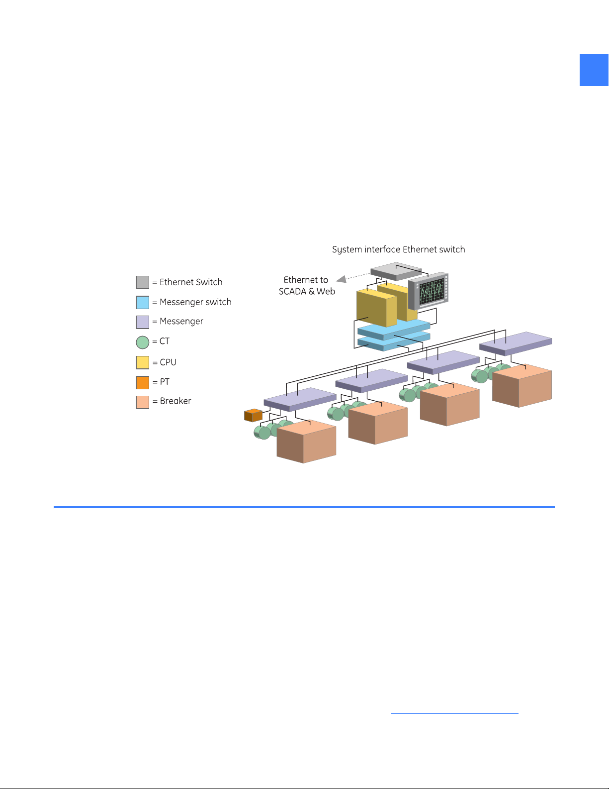
1 System architecture
The Entellisys™ Low-Voltage Switchgear architecture is unique. The central processor unit (CPU)
is the basis of this new protection-and-control architecture. The CPU provides protection and
control functions over the entire low-voltage switchgear system.
The key advantage of this architecture is that the CPU has all the information from all circuit
breakers simultaneously. The architecture also has built in redundancy to increase system
availability.
Figure 1-1 Entellisys LV Switchgear simplified architecture
1
1.1 Description of operation
Current transformers (CTs) and potential transformers (PTs) measure current and voltage and
transmit the analog information to the EntelliGuard™. The Messenger digitizes and sends the
information over the Messenger communication network to two redundant CPUs.
The CPUs make protection decisions, capture events, process waveform data, and provide
status information. For example, if the CPUs identify a trip condition at a circuit breaker, the CPU
alerts the EntelliGuard Messenger at that circuit breaker, which then actuates the circuit breaker
and returns the circuit breaker status to the CPU.
Modbus
external components such as the Entellisys HMI, SCADA, or other Building Automation Systems.
The Human Machine Interface (HMI) is the central user interface for the system. HMIs are
touchscreen computers located in-gear or near-gear (see Touchscreen HMI
Remote HMIs are available for desktop users who want to view the switchgear from their office.
®
communication, an open industry standard protocol, is provided as an interface to
on page 24) and
Description of operation 13
Page 14
Discrete I/O is provided for customer-specific inputs and outputs. This equipment is resident in
1
the switchgear and is connected through the CPUs. Discrete I/O and custom control schemes
will run in the CPUs if enabled.
In summary, Entellisys changes the protection paradigm from individual circuit protection to
system protection.
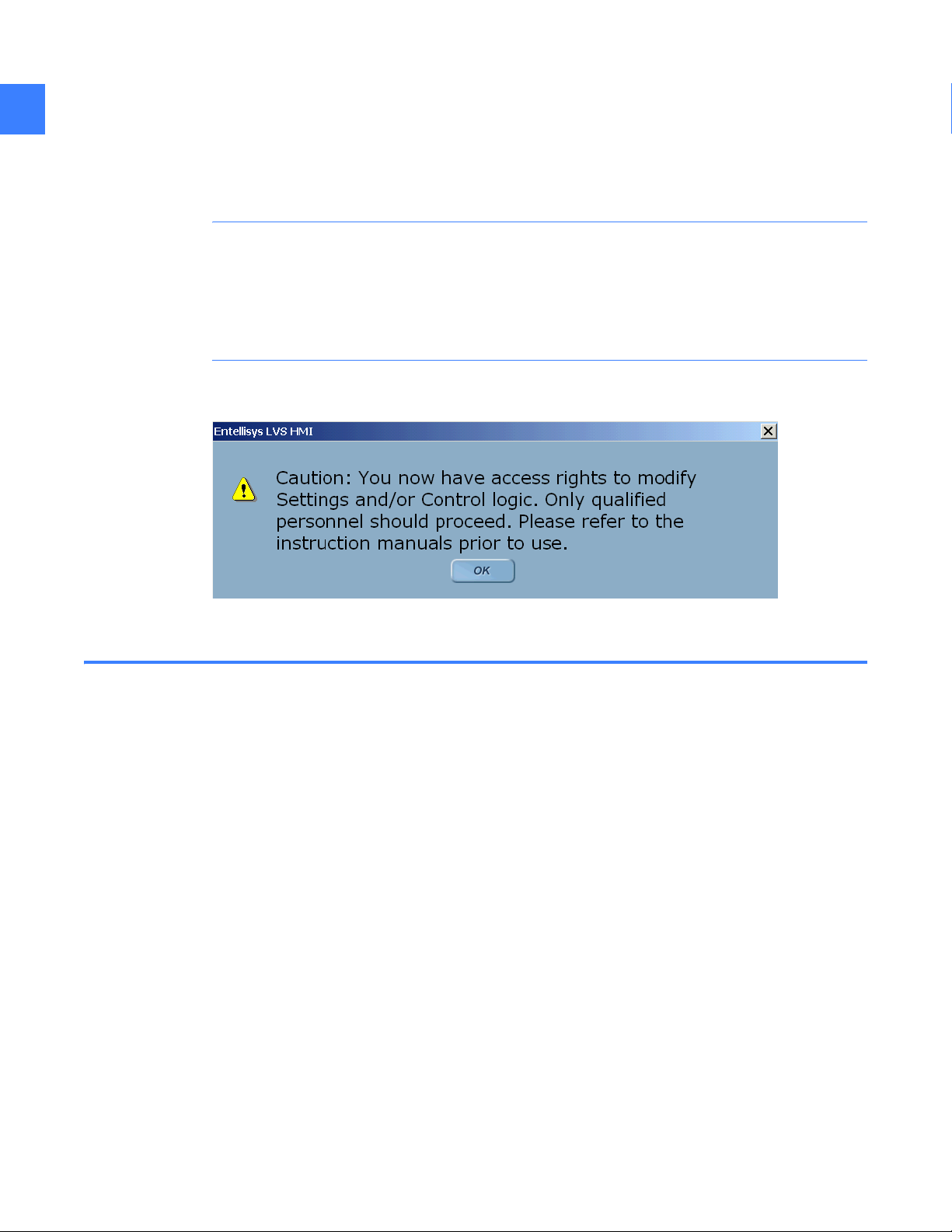
CAUTION: Users that have been assigned Group Permissions by the System Administrator for
features that allow the changing of settings and/or access to control functions must be
established as qualified personnel only. See Chapter 4 in DEH-430, Entellisys Low Voltage
Switchgear System Administrator Manual, for more information about programming user
permissions. As a reminder, users with such privileges will be presented with the following
screen upon initial login:
Figure 1-2 Initial login Caution screen
1.2 Switchgear installations
There are two primary installation methods in the switchgear:
• Standard
• Split-redundant
With standard installation, redundant components such as the CPUs, Messenger switches, and
UPSs are installed together in the equipment. This method optimizes footprint and convenience
of maintenance.
With split-redundant installation, redundant components such as the CPUs, Messenger
switches, and UPSs are split-up with at least one switchgear stack separating them. This
method optimizes system availability.
For more information, see DEH-237 Entellisys Low Voltage Switchgear Installation and
Maintenance Instruction Guide.
System architecture14
Page 15
1.3 System components
Following are brief descriptions of each component in the Entellisys system.
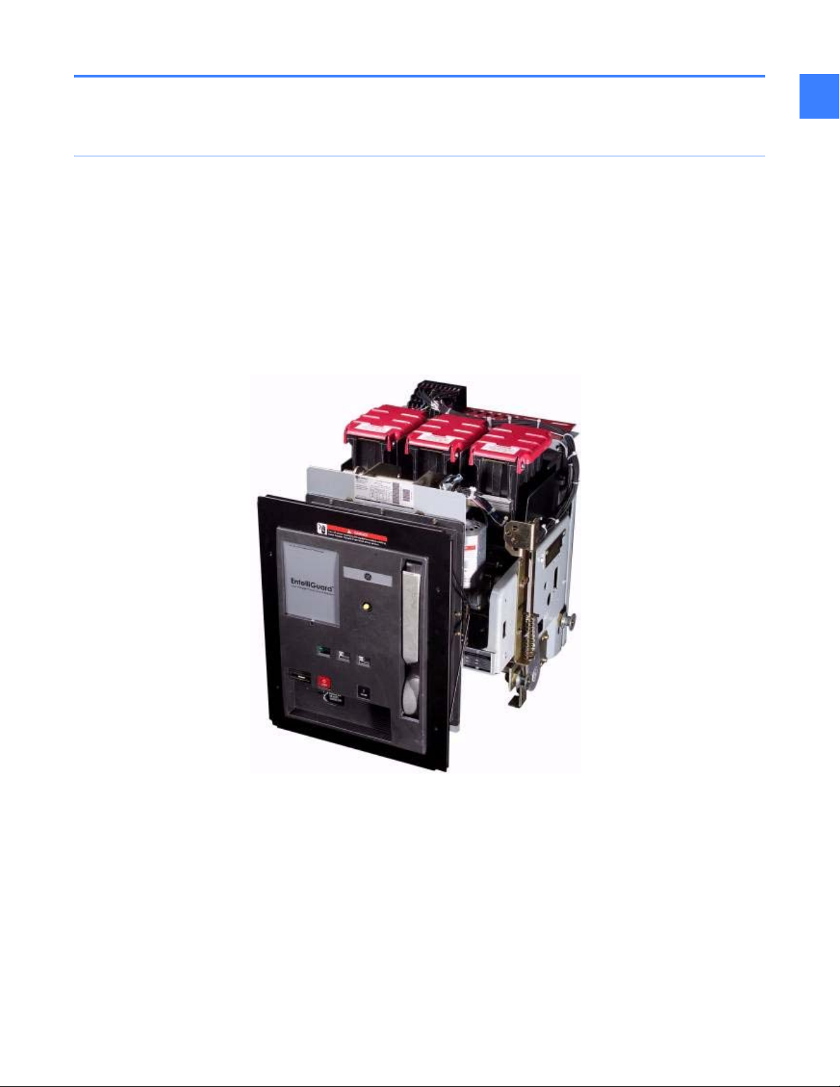
1.3.1 EntelliGuard circuit breaker
EntelliGuard low-voltage power circuit breakers control and protect power circuits up to
600 volts. They will safely switch loads and automatically clear circuits when abnormal
conditions occur. These include short circuits, sustained overloads, ground faults, and other
programmable conditions.
The EntelliGuard circuit breakers are available in 800 ampere, 1,600 ampere, 2,000 ampere,
3,200 ampere, 4,000 ampere, and 5,000 ampere frame sizes. These values represent the
maximum continuous-current rating of each frame.
Circuit breakers may be equipped with a combination of accessories and interlocking devices.
Figure 1-3 EntelliGuard small frame circuit breaker
1
•The network interlock accessory selectively prevents the closing of specific circuit
breakers in the electrical distribution network. The CPU sets and resets network interlock
devices remotely while continuously monitoring their status. For example, in a
double-ended substation, these devices could be used to interlock the main and tie
circuit breakers to prevent connecting two unsynchronized power sources.
•The bell alarm lockout accessory prevents a circuit breaker from closing after receiving
a trip command from the EntelliGuard Messenger. Closing of the circuit breaker is
permitted only after the lockout is reset manually at the front of the circuit breaker.
For more information, see the following EntelliGuard Circuit Breaker Instruction Books:
• DEH-201 EntelliGuard Power Circuit Breakers 800-2,000A Frames, 240-600Vac Users Guide
• DEH-202 EntelliGuard Power Circuit Breakers 3,200-5,000A Frames, 240-600Vac Users Guide
System components 15
Page 16
1
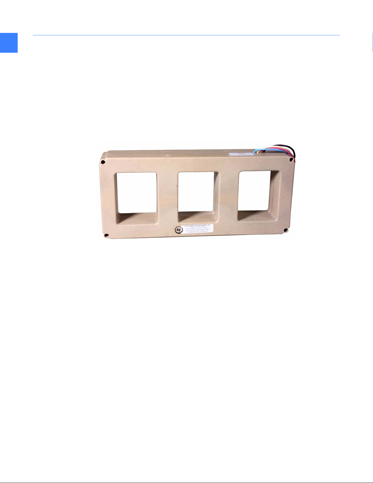
1.3.2 Current transformers
Current transformers (CTs) are sensors that measure current. Each circuit breaker requires input
from three CTs (one per phase) and an optional neutral CT. Unlike traditional switchgear, this
single set of CTs provides the necessary current sensing for all needs including protection,
metering, and control.
The CTs are attached to the power bus behind the circuit breaker in the circuit breaker
compartment. Only Entellisys CTs may be used with the Entellisys system.
CTs either come in a 3-pack (shown in Figure 1-4) or as single CTs.
Figure 1-4 CT 3-pack
System architecture16
Page 17
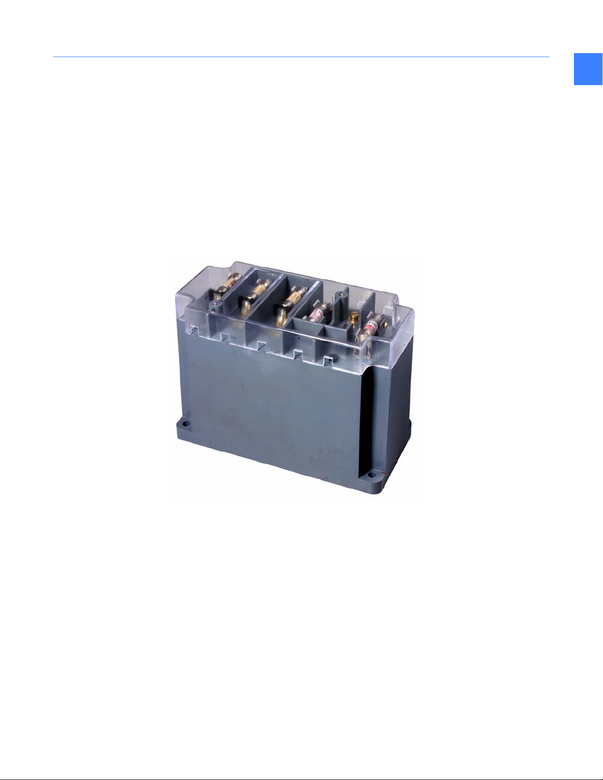
1.3.3 Potential transformers
Potential or voltage transformers (PTs) are sensors that measure voltage. Unlike traditional
switchgear, only the main (or source) circuit breakers in the system require PTs. This hardware
and wiring reduction is possible because of the central processor architecture and the sampling
synchronization maintained by the system.
Three PTs, one for each phase, are required on the main circuit breakers in the system. The
remaining circuit breakers reference one circuit breaker with physical PTs and use that source's
voltage readings for metering calculations. This source reference may change as the system
topology changes.
The PTs are located outside the circuit breaker compartments in auxiliary compartments.
Figure 1-5 Entellisys PT
1
System components 17
Page 18
1
1.3.4 EntelliGuard Messenger
The EntelliGuard Messenger electronic device provides the interface between the circuit
breakers and the CPUs in the Entellisys system.
The following is a summary of the Messenger’s functionality:
• Digitizes all switchgear signals
• Communicates the raw samples to CPUs via the Messenger network
• Controls the circuit breaker
• Performs independent backup trip capability at all times
• Powered by dual 120v control power sources or self-powered from the current sensors
• Provides LED illumination of circuit breaker status, power status, communication status, and
GE “Locator” information
• Provides seal-able switches to set CT rating, and (long time) multiplier setting
• Provides a test connector for trip curve testing using the Entellisys System Test Kit
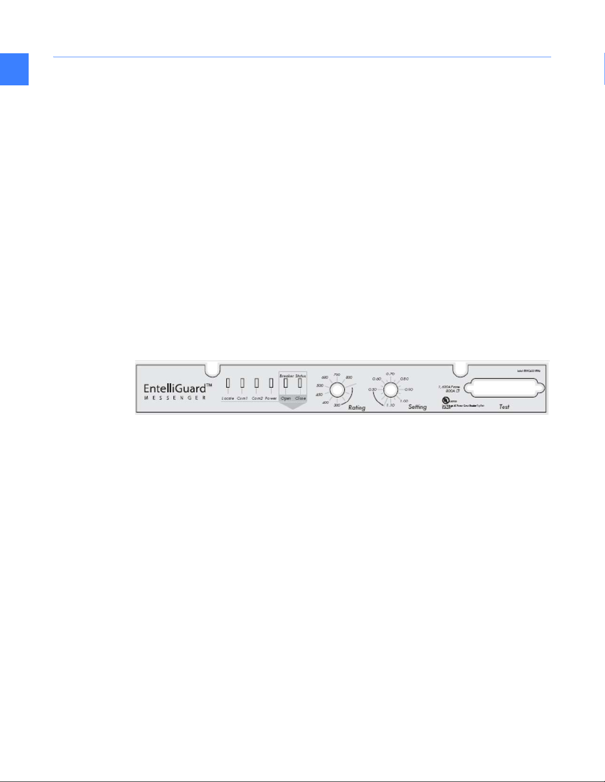
1.3.4.1 Messenger User Interface
The Messenger User Interface, as show in Figure 1-6, is described below.
Figure 1-6 Messenger front
LED Indicator Lights
• Locate: LED blinks for 10 or 30 seconds on command from the HMI to help operator
physically locate a circuit breaker in the switchgear lineup.
• Com1, Com2: Illuminates when Ethernet communication is plugged in and ready to
communicate.
• Power: Illuminates when either Control Power A or Control Power B sources are powering the
messenger.
• Circuit Breaker Status Open: Illuminates when the circuit breaker is Open. This sensor is
independent of the circuit breaker Close sensor.
• Circuit Breaker Status Closed: Illuminates when the circuit breaker is Closed. This sensor is
independent of the circuit breaker Open sensor.
Switches
• Rating: Ampere rating of the circuit in use. Maximum value is the CT Rating.
• Setting: Multiplier setting for Long Time Overcurrent Protection, specified as X times the
Rating switch value.
Rating Label
• Frame: Circuit breaker frame size, in Amperes, represents the maximum continuous-current
rating.
• CT: Maximum Ampere rating of the CTs.
System architecture18
Page 19

Test Connector
Connection point between the Entellisys System Test Kit and the Messenger.
Figure 1-7 EntelliGuard Messenger
The Messenger is located directly above the circuit breaker compartment.
1.3.5 Compartment ID button
The Compartment ID button stores compartment configuration information in non-volatile
memory. It informs the system about the circuit breaker residing in the cubicle.
The Compartment ID button is shipped inserted into the EntelliGuard Messenger, tethered to the
equipment, and does not require any user interface during normal operation. It remains within
the switchgear cubicle at all times.
1
WARNING! Compartment ID buttons are set at the factory and are not interchangeable
between compartments. Failure to utilize the correct compartment ID button can result in
personal injury and damage to equipment.
The ID button provides the system with necessary information such as circuit breaker frame
size, CT size, and overcurrent protection capabilities as follows:
• Ground fault protection always on
• Ground fault protection always off
• Ground fault protection switchable (enabled/disabled) in the HMI
If the ground fault protection options need to change, a replacement ID button must be ordered
(GE CAT# ETSCOMPID).
System components 19
Page 20

Figure 1-8 Compartment ID Button un-tethered from switchgear
1
1.3.6 Messenger communications network
The Messenger communications networks are closed, dedicated LANs for transmitting
information between the Messengers and the CPUs in the system. The LANs are for the
Entellisys system only and should never be connected to other networks.
CAUTION: Failure to maintain a dedicated LAN will result in the EntelliGuard Messenger
reverting to back-up Overcurrent protection.
A Messenger switch is required to route information appropriately. The communication wiring
required is 100BaseT, CAT5 cables.
Each CPU resides on a separate network, providing redundant communications.
1.3.7 Messenger switch
The Messenger switch enables the communication network between the Messengers and
corresponding CPU. A Messenger switch is required for each of the two redundant networks. The
number of ports provided is determined by the number of circuit breakers in the system. Each
circuit breaker requires its own port in the switch.
The largest switch provides only 24 ports. If the number of circuit breakers in the system
exceeds 22, a pyramid switch scheme, utilizing multiple switches, is required.
System architecture20
Page 21
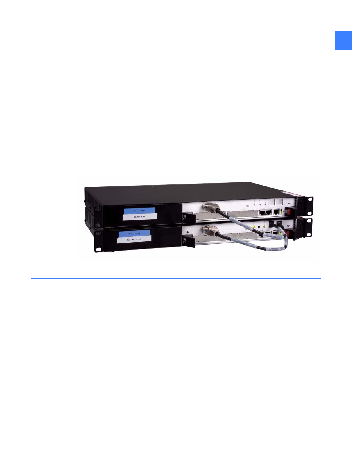
1.3.8 CPU
1
The CPU is a rack-mount industrial computer running a real-time operating system. The CPU
provides the processing capability to support all switchgear functions. Two redundant CPUs
(CPU A and CPU B) are used per lineup, supporting up to 30 circuit breakers.
The CPUs run simultaneously. If one CPU has an issue, the other continues to run providing
redundancy. One CPU should be running at all times to maintain the highest level of protection.
In the event that the Messenger-to-CPU communication network is down or power to the CPU is
not available, the EntelliGuard Messenger will provide back-up overcurrent protection
functionality.
The redundant CPUs are synchronized by a common connection to a synch clock. Each CPU has
a slot for synch clock, although only one synch clock is used per system. The synch clock is
programmed for either 60 Hertz or 50 Hertz frequency operation.
Each CPU has two slots for optional discrete I/O cards.
Figure 1-9 Redundant CPUs with synch clock connection
1.3.9 Synch clock
To maintain system synchronization, a mechanism exists to provide a single sampling time
source. This time source is provided on a separate hardware card, called the Synch Clock. The
Synch Clock sits in CPU A and has a connection to CPU B.
In the event of an issue with the Synch Clock or its connections, the CPUs fall-back to software
synch functionality. When this occurs CPU A maintains full functionality. As time drifts, CPU B
may suspend advanced multi-source protection and may not be able to provide metering
information for the circuit breakers without PTs. If CPU A is powered down to provide
maintenance, CPU B will continue to run all functions.
System components 21
Page 22

1
1.3.10 Discrete I/O
The discrete I/O equipment provides programmable input and output logic for
customer-specific requirements.
Examples include the following:
• Sound a horn when a circuit breaker is open
• Trigger an output when voltage exceeds a value
The redundant discrete I/O option provides signal processing to/from either CPU. One CPU (the
Master) processes the information and responds. The other provides a backup of the Master
fails. Redundant discrete I/O is recommended if any of the signals are critical to the operation of
the system. Critical I/O examples include the following:
• Inputs to automatic throw-over schemes
• Inputs that must trip circuit breaker (such as high transformer pressure)
For more information on discrete I/O, see Discrete I/O
1.3.10.1 Discrete I/O cards
The input and output signals from the CPU are transferred through the discrete I/O cards. Each
card supports 64 bi-directional points that range from 0 to 5 volts. A maximum of two cards
may be inserted for a total of 128 I/O points. The cards come installed in the CPU upon
purchase.
1.3.10.2 Discrete I/O cable
This cable connects the discrete I/O card to the terminal block. Each cable transmits 64 I/O
points.
1.3.10.3 Terminal block
The terminal block accepts 64 I/O signals from the discrete I/O card through a single cable and
breaks out the individual signals into 64 terminals for wiring.
1.3.10.4 “OR” boards
These boards are only required for redundant discrete I/O. The output signals from both CPUs
must be “Horde” together, between the terminal blocks and the relay blocks, to prevent
increased voltages from damaging the relays. Each “OR” board supports 16 output signals.
on page 149.
1.3.10.5 Relay blocks
The relay blocks hold solid state input and output relays (16 per block).
Relay blocks are configured as all inputs or all outputs. Unused discrete I/O points may have
relays left off.
1.3.10.6 Relays
The input relays transform the customer input (120 Vac or 24-125 Vdc) to 5V inputs for the
Entellisys system.
The output relays are either opened or closed based on programmable logic in the Entellisys
system.
System architecture22
Page 23
1.3.10.7 Discrete I/O customer interface wiring
The customer interface to the discrete I/O is provided at the I/O module relay blocks. These relay
blocks and the customer wire termination points are mounted in the discrete I/O cubicle and are
accessed from the front of the switchgear. Control conduits are terminated in the rear cable
compartment and the discrete I/O wiring is routed to the front of the switchgear through an
opening in the discrete I/O cubicle rear barrier.
1.3.11 System interface Ethernet communication network
The system interface Ethernet communication network is a 10/100 Mbps Ethernet LAN that
provides an interface into the Entellisys system for systems such as the Entellisys HMI, SCADA
systems, building automation, HVAC systems or other. The system interface Ethernet
communication network provides information and control of all circuit breakers in the system.
The external communications network will use 100BaseT (copper twisted pair) CAT5 or better
cabling. A fiber optic connection is available as an option.
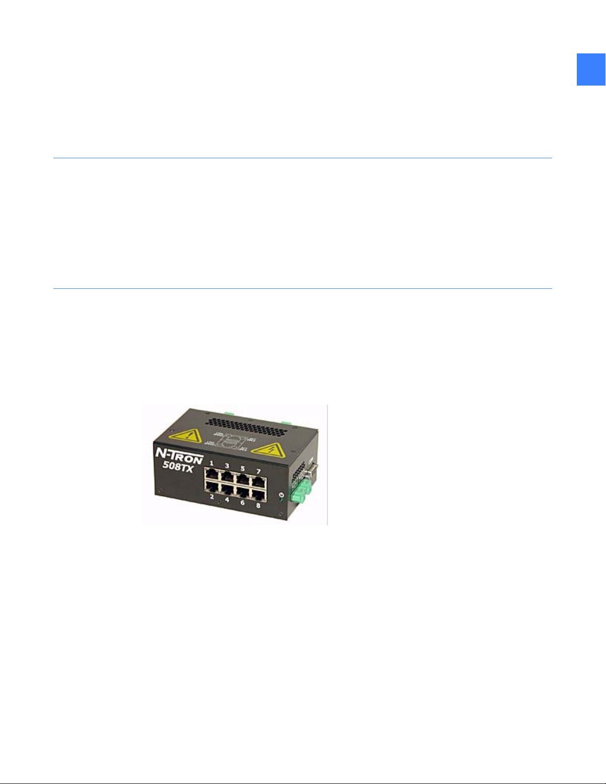
1.3.12 System interface Ethernet switch
The interface between the Entellisys system and the external world is through the system
interface Ethernet switch, an industrial hardened 10/100 Mbps Ethernet switch. An 8-port
copper model is standard. Optionally customers may choose a 9-port model with an additional
fiber port for external gear communication. The fiber port supports 100FL connections only.
1
Figure 1-10 Ethernet switch, 8-port
System components 23
Page 24

1
1.3.13 Touchscreen HMI
The system interface for the Entellisys switchgear will be through one or more touchscreen
computer displays. The display is driven by a separate computer and communicates to the
CPUs through an Ethernet connection. The System Interface Ethernet Switch provides the
physical interface.
The HMI communicates primarily with one of the CPUs but can switch to the other in event of a
failure. Functionality provided by the HMI includes:
• Programmable user login to grant/deny access to specific features
• Animated one-line that shows the current status of the entire system
• Circuit breaker status, circuit breaker control
• Metering, demand logging, harmonics
• User settings for overcurrent protection, relay protection, advanced multi-source protection.
This may be writable or read-only depending on permissions granted.
• Customer-specific discrete I/O programming and status
• Customer-specific control scheme programming and status
• Sequence of events
• System health – showing the health of the Entellisys equipment
• Alarm panel – setup, panel status, e-mail configuration for alarms
NOTE: The HMI is not critical to the protection functionality of the system. The HMI can be
brought down for service with no loss of protection in the system.
1.3.13.1 In-gear HMI
Typically a touchscreen HMI is installed in the switchgear. This is deemed an “in-gear” HMI.
A redundant in-gear HMI is available as an option. The redundant HMI is also a touchscreen HMI
located in the gear.
1.3.13.2 Near-gear HMI
Optionally, a touchscreen HMI may be installed near the switchgear equipment, but away from
the hazardous arc flash zone. This can be in a separate stack or in a wall-mount box up to
250 feet from the switchgear. This is deemed a “near-gear” HMI.
System architecture24
Page 25

1.3.14 Remote HMI
The Entellisys system offers desktop access to the switchgear with the same HMI software
installed in the gear. The remote HMI software can be installed on any Windows 2000 desktop
computer and requires an intranet connection to the switchgear. The intranet connection is
connected to the system interface Ethernet switch.
Two versions of remote HMI are offered:
• User Interactive
Permissions are programmable and can be set for full Administrator access down to Guest
access.
• Viewer
Allows read-only access to the system.
1.3.15 VPN firewall device
Virtual Private Network (VPN) firewall device provides business-class network security providing
Denial of Service (DoS) protection and intrusion detection using Stateful Packet Inspection (SPI),
URL access and content filtering, logging, reporting, and real-time alerts. Up to eight users can
access the system simultaneously.
1
It is strongly recommended that anytime an Entellisys system is connected to the intranet, a
VPN firewall be installed to protect the Entellisys system from network threats.
For more information, see DEH-430 Entellisys Low Voltage Switchgear System Administrator
Manual.
1.3.16 Control power
Control Power is 120 Vac, 50 and 60 Hz only. Uninterruptible power is provided standard with
each system. The control power scheme is specific to each installation and constructed from
standard elements using defined practices for Entellisys control power distribution.
1.3.17 UPS
Two Universal Power Supplies are installed in the switchgear to provide backup power to the
control power network. The UPSs are powered from the primary power buses (utility or
generator) and are redundant.
The UPS serves all 120 Vac control power network devices. It does not power the charging
motors of electrically operated circuit breakers.
For more information on the Control Power Network, see Control power and UPS configuration
on page 209.
For more information on the UPS, see the “GE Digital Energy GT Series™ - UL, Product
Description” at www.gedigitalenergy.com
.
System components 25
Page 26

1
1.3.18 UPS to HMI connection
The Entellisys system provides event/alarm/e-mail information when the UPS A has gone on
battery backup and when the batteries are low. When the batteries are low, the HMI safely shuts
down to avoid abrupt power interruption. To enable this communication, a link between UPS A
and the primary touchscreen HMI is established. This link is a serial connection between the
DB-9 serial port connection on the UPS and the DB-9 serial port connection on the HMI. Since
distances between the HMI and UPS may exceed serial cable distances, a pair of RS-232 to
RS-485 converters are installed at each end to accommodate the cabling distance through the
switchgear.
1.3.19 RS-232 to RS-485 converter
This device converts RS-232 signals to RS-485 signals. This is required to support the cable
lengths in the switchgear. RS-232 imposes a distance limitation of only 15 meters. RS-485 can
transmit data over distances up to 1.2 km.
1.3.20 Entellisys System Test Kit
The Entellisys System Test Kit is a portable test instrument designed for field testing of the
Entellisys Low-Voltage Switchgear system.
The test kit includes the following features:
• Simulate power-line characteristics for a single circuit breaker in the Entellisys Low-Voltage
System
• Verify the function/operation of the protection system
• Overcurrent protection tests – long time, short time, instantaneous and ground fault
protection tests
• Single point relay protection tests (overvoltage, undervoltage, over frequency, under
frequency, power reversal and phase loss, high current test)
• Verify the calibration of the trip time current curve
• Verify the operation of the circuit breaker actuation in “Trip mode”
• Perform tests without trips in “No Trip mode”
• Ground Fault Defeat function provides temporarily suspension of all ground fault protection
in the system
• Automatically retrieves system configuration for increased productivity
• Displays a summary of all protection configuration
• Saves test results to be reviewed later
• Windows Interface for ease of use
• Operation from 120 Vac
For more information, see DEH-233 Entellisys Low Voltage Switchgear System Test Kit User
Manual.
1.3.21 Clamp circuit
The clamp circuit is an intermediary device between the CTs with 150ampere and 400ampere
ratings only. The clamp circuit protects the Messenger from large current outputs from the CTs.
The clamp circuit is installed in the circuit breaker compartment on the left-hand side sheet.
System architecture26
Page 27

2Specifications
2.1 Environmental
Storage/shipping temperatures
–40 to 85° C
Operating temperatures
0 to 40° C ambient, indoor use
Humidity
5% to 95%, non-condensing, indoor use
2.2 Type tests
Tests are split into two categories:
• EntelliGuard Messenger Tests – the primary protection control element
2
• Entellisys System Tests – the complete system
Table 2-1 Type tests
Type Name EntelliGuard Messenger
Tests
EMC/Transient Harmonic Currents IEC60947-2 sec.F.4.1.2
EMC/Transient Current Dips and
Interruptions
EMC/Transient Fast Transient Burst IEC61000-4-4
EMC/Transient Voltage/Current Surge
Immunity
EMC/Transient Electrostatic Discharge
Immunity
EMC/Transient 1MHz Oscillatory SWC IEC 60255-22-1
EM emission Conducted FCC part 15, subpart B, Class A
IEC60947-2 sec. F.4.2
ANSI C37.90.1
IEC61000-4-5
IE255-22-5
IEC60947-2 sec. F.4.3
IEC60255-6
ANSI C37.90.1
Entellisys System Tests
ANSI C37.90.1
ANSI C62.41
IEC61000-4-4
ANSI C62.41
IEC61000-4-4
EN61000-4-2
ANSI C37.90.1
EM emission Radiated FCC part 15, subpart B, Class A
RFI Electromagnetic Field
Immunity
IEC60947-2 sec. F.4.4
Environmental 27
Page 28

Table 2-1 Type tests
Type Name EntelliGuard Messenger
Tests
Entellisys System Tests
22
RFI RFI with portable
transmitters
RFI ANSI Radiated
Susceptibility
RFI Conductive RF Immunity IEC60255-22-6
Environment Dry Heat IEC60947-2 sec. F.7
Environment Thermal Shock IEC60947-2 sec. F.9
Environment Damp Heat IEC60947-2 sec. F.8
Environment Humidity IEC60947-1
Mechanical Sinusoidal Vibration IEC255-21-1
Safety Dielectric Strength IEC60255-6 ANSI C37.20.2 Paragraph 5.3
IEC60255-6
ANSI C37.90.2 ANSI C37.90.2
IEC60068-2-1
IEC60068-2-2
IEC60947-2 sec. F.8
Safety Insulation Resistance IEC60255-6
Safety Impulse Voltage Withstand IEC60255-6
Magnetic Power Frequency
Magnetic Power Magnetic Field
Voltage Overvoltage ANSI C84.1
Voltage Undervoltage ANSI C84.1
Voltage Ramp voltage ANSI C84.1
Voltage Line Interruption ANSI C84.1
2.3 Approvals
IEC61000-4-8
Magnetic Field
IEC61000-4-9
Immunity
IEC 61000-4-11
IEC 61000-4-11
UL Listed – Low Voltage AC Power Circuit Breaker Trip Unit - E-48428
FCC Class A listed
Specifications28
Page 29
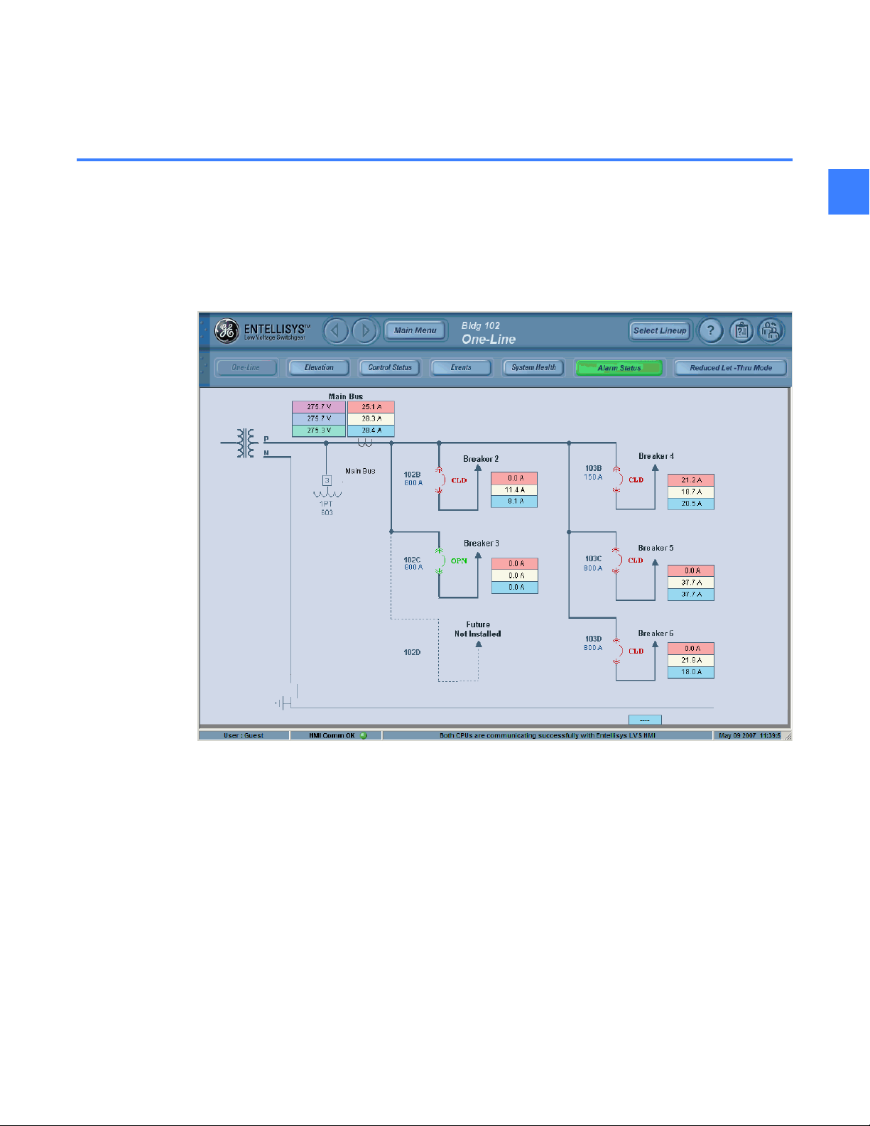
3 HMI Basics
3.1 Entellisys HMI Overview
When the user approaches the HMI, the HMI is logged in as guest and the default screen will be
displayed.
Figure 3-1 One-Line diagram
3
Entellisys HMI Overview 29
Page 30

3.1.1 The Header Pane
Figure 3-2 The header pane
3
Navigation buttons
Forward and back buttons
Opens a dynamic floating menu. The menu options very depending on the current
login credentials
On-line help
About - displays current HMI software revision
Login/Logout
Standard Display Screen buttons
Each of the status screens below are viewable before logging into the system.
•One-Line
•Elevation
•Control Status
•Events
•System Health
•Alarm Status
Enables/disables Reduced Energy Mode, see Reduced Energy Let-Thru Mode
on page 129
HMI Basics30
Page 31

3.1.2 The status bar
The status bar provides the user with important information about the status of the HMI
Figure 3-3 The header pane
User
Current user logged in the HMI (Max 20 characters)
Communication Status
Indicates that the communication with the CPUs are in one of 4 different states
• Green - HMI is communicating with both CPUs
• Yellow - HMI is communicating with one CPU
• Red - HMI is not communicating with either CPU
• Gray - HMI is in off-line mode
Message Marquee
The message marquee will elaborate on the communication status or other pertinent user
information.
Date and Time
The Date and time cell displays the computer time of the HMI PC
3
3.1.3 Main Menu
In addition to the standard display screens, depending on the user credentials, there will be
additional buttons to administer the system. Guests and operators will be presented with the
menu items in Figure 3-4
Figure 3-4 The main menu for guests and operators
User Settings: Includes Relay settings, Metering, Control,
Preventative Maintenance and HMI preferences, see relevant
sections in this manual
Job Documentation: View imported job documents, see Job
Documentation on page 33
Entellisys HMI Overview 31
Page 32

3.1.4 Breaker Status Screen
The Breaker Status screen is opened after clicking on a breaker either on the oneline or the
Elevation screens. The Breaker Status screen gives current and voltage information, breaker
configuration and provides links to view settings, metering and control.
3
Figure 3-5 Breaker Status screen
Navigation buttons
Previous / Next Breaker: Cycles between breakers in order of breaker
number
Test Mode: Active when the customer test cart is plugged into the
messenger
HMI Basics32
Page 33

3.2 Job Documentation
The job documentation link allows all users access to the relevant job related documents. An
Entellisys administrator may add job drawings and user manuals from a USB drive.
Documents are restricted to the following file types
• *.txt - plain text document
• *.pdf - Portable Document Format - Adobe Acrobat format
• *.tif - Targa Interchange File Format - graphic files
Figure 3-6 On-Line Job Documentation
3
To import documents, click on the Import Job Files and select the files from the USB stick
(required). Import Job Files will be disabled if less than 15% of the disk space is remaining.
NOTE: Once imported, files can not be deleted
Job Documentation 33
Page 34

3
3.3 Controlling circuit breakers
Entellisys allows users to control EntelliGuard circuit breakers from the HMI. A circuit breaker
may be commanded to open, close or trip. To locate or confirm the circuit breaker shown on the
HMI screen matches the physical circuit breaker, the locator LED on each EntelliGuard
Messenger can be set to flash for 10 or 30 seconds.
To control a circuit breaker, navigate to the Breaker Status screen and click Control as shown in
Figure 3-5. The Breaker Control screen appears. The Breaker Control screen resembles
Figure 3-7 when the circuit breaker is open. The Breaker Control screen resembles Figure 3-8
when the circuit breaker is closed.
Figure 3-7 Breaker Control screen for open circuit breaker
Figure 3-8 Breaker Control screen with closed circuit breaker
HMI Basics34
Page 35

3.3.1 Block other HMIs
Any HMI that is designated as a Local HMI can block other HMIs from operating circuit breakers.
To designate an HMI as local, click the Modbus Security tab under the Maintenance menu.
When the check box on that screen is checked, the HMI is the Local HMI.
To block other HMIs from the local HMI, click the Control button under the Breaker Status
screen. In the Breaker Control screen there is a check box to Block Other HMIs.
Only Local HMIs have the ability to block other HMIs. If the Block Other HMIs check box is grayed
out, it is not setup as a Local HMI.
CAUTION: When controlling circuit breakers through a local HMI it is recommended that users
block all HMIs to prevent remote circuit breaker control. This step is in addition to normal
lock-out tag-out procedures when applicable.
3.3.2 Open circuit breaker (electrically operated circuit breakers only)
To open a circuit breaker, click OPEN BREAKER on the Breaker Control screen. A dialog box
appears for verification that the circuit breaker should be opened. Click Yes to open the circuit
breaker. Once the open breaker command is verified, the EntelliGuard Messenger uses the
Shunt Trip to actually open the circuit breaker.
3
If the open breaker command is successful, the circuit breaker opens and the Current State of
the circuit breaker on the Breaker Control screen changes from Closed to Open. If the circuit
breaker does not open, examine the Sequence of Events. One of the following events may be
present:
• Attention Breaker Open Failed Shunt Trip
• Note Messngr Reports CPUA (or B) Command Timed Out
See Table A-2 for more information.
3.3.3 Close circuit breaker (electrically operated circuit breakers only)
To close a circuit breaker, click CLOSE BREAKER on the Breaker Control screen. A dialog box
appears for verification that the circuit breaker should be closed. Click Yes to close the circuit
breaker. Once the close breaker command is verified, the EntelliGuard Messenger uses the Close
Coil to actually close the circuit breaker.
If the close breaker command is successful, the circuit breaker closes and the Current State of
the circuit breaker on the Breaker Control screen changes from Open to Closed. If the circuit
breaker does not close, examine the Sequence of Events. One of the following events may be
present:
• Attention Breaker Close Failed
• Breaker Close Command Rejected Breaker Locked Out
• Note Messngr Arbitrated Command From CPUA (or B)
• Note Messngr Reports CPUA (or B) Command Timed Out
Controlling circuit breakers 35
Page 36

See Table A-2 for more information.
3
3.3.4 Trip circuit breaker
To trip a circuit breaker, click TRIP BREAKER on the Breaker Control screen. A dialog box
appears for verification that the circuit breaker should be tripped. Click Yes to trip the circuit
breaker. Once the trip breaker command is verified, the EntelliGuard Messenger uses the Flux
Shifter to actually trip the circuit breaker.
If the trip breaker command is successful, the circuit breaker trips and is locked out, and the
Current State of the circuit breaker on the Breaker Control screen changes from Closed to
Open-tripped. If the circuit breaker does not trip, examine the Sequence of Events. One of the
following events may be present: (See Table A-2 for more information)
• Attention Breaker Trip Failed Flux Shifter
• Note Messngr Reports CPUA (or B) Command Timed Out
3.3.5 Locator LED
To turn on the locator LED for 10 or 30 seconds, click 10 Seconds or 30 Seconds on the Breaker
Control screen. The locator LED on the particular EntelliGuard Messenger blinks for the
appropriate length, making identification easy.
3.3.6 Troubleshooting
Breaker Control screen only shows Trip option
• Open and close commands are only available for electrically operated circuit breakers.
Breaker Control screen shows Open, Close and Trip options at the same time
• Circuit breaker contact position is unknown.
Breaker control screen appears grayed out
• User does not have permissions to control circuit breakers.
Breaker does not open when command is issued
• Verify remote racker is not in.
HMI Basics36
Page 37

4 Metering
Entellisys provides a number of metering quantities, including RMS current and voltage,
demands, energy values, power factors, and harmonic data. There are four levels of metering
available: basic metering, expanded metering, demand metering, and advanced metering.
4.1 Basic metering
Basic metering is always available in Entellisys (i.e., it is not an optional feature). Basic metering
includes RMS current per phase (I
Entellisys provides line-to-neutral (VA, VB and VC) and line-to-line (VAB, VBC and VCA) voltages. For
delta PTs, Entellisys provides line-to-line voltages only.
The RMS voltages and currents are averages over one second (nominally 60 cycles of the
fundamental power system frequency at 60 Hz) and include harmonics.
4.2 Expanded metering
, IB, IC and IN) and RMS voltage per phase. For wye PTs,
A
4
Expanded metering (also referred to as detailed metering) is an optional feature in Entellisys.
Expanded metering can be enabled for each circuit breaker, up to the maximum number of
purchased expanded metering options. With the expanded metering option enabled, Entellisys
provides the following quantities:
• Positive watt-hours, per phase and total
• Negative watt-hours, per phase and total
• Positive var-hours, per phase and total
• Negative var-hours, per phase and total
• Apparent VA-hours, per phase and total
• Real power (watts) per phase and total
• Reactive power (vars) per phase and total
• Apparent power (VA) per phase and total
• Power factor per phase and total
• Minimum power factor, including date and time, per phase and total
• Maximum power factor, including date and time, per phase and total
• System Frequency
Per phase quantities are only available for wye connected systems.
Watt-hours, var-hours, and VA-hours are sums starting from when the option was last applied,
or since the last time the values were reset through the HMI.
Real, reactive, and apparent power quantities are averages over one second (nominally
60 cycles of the fundamental power system frequency at 60 Hz) and include harmonics. Power
factors are calculated by dividing real power by apparent power.
Basic metering 37
Page 38

Watts and watt-hours are positive when the current is flowing from line to load and negative
when the current is flowing from load to line. Vars and var-hours are positive when the current is
lagging the voltage and negative when the current is leading the voltage.
The power factor is positive (i.e., lagging) when watts and vars have the same sign and negative
when watts and vars have the opposite sign. Minimum and maximum comparisons are done
based on magnitudes (e.g., a power factor of –0.866 is greater than a power factor of 0.707).
System frequency is calculated using phase A to N in WYE systems and phase A to B in Delta
4
systems
4.3 Demand metering
Demand metering is an optional feature in Entellisys. Demand metering can be enabled for
each circuit breaker, up to the maximum number of purchased demand metering options. When
the demand metering option is enabled, Entellisys provides the following quantities:
• All quantities available with the expanded metering option
• Previous interval kilowatt (kW) demand
• Maximum kW demand
• Previous interval kilovar (kvar) demand
• Maximum kvar demand
• Previous interval kVA demand
• Maximum kVA demand
• Demand logging – kWh, kvarh, kW demand, kvar demand, power factor
Per phase quantities are only available for wye connected systems.
Demands are averages over a demand interval. Entellisys supports both block and rolling
demand intervals:
Table 4-1 Demand interval and subinterval combinations supported in Entellisys
Subintervals per
interval
1 (block demand) Xxxxxxxxxxx
2 xxx xxxx x
3 xx xx x x
4 xxx x
Subinterval length, minutes
1234561015203060
5 xxxx x
6 xx x x
10 xxx x
12 xx
Metering38
Page 39

Table 4-1 Demand interval and subinterval combinations supported in Entellisys
Subintervals per
interval
Subinterval length, minutes
1234561015203060
xx x
For block demand, Entellisys calculates the average demand over the duration of the demand
interval. For rolling demand, Entellisys calculates the average demand over the previous N
subintervals, where N is the number of subintervals per demand interval. This is done at the end
of each demand subinterval. Demand intervals are synchronized to the hour boundary. For
example, if the demand interval or subinterval length is 15 minutes, the demand intervals end
on the hour and at 15, 30, and 45 minutes past the hour.
The programmed interval length (block demand) or subinterval length and the number of
subintervals per demand interval apply to all circuit breakers at which demand metering is
enabled.
Demand log entries are added at the end of each demand interval or subinterval.
4.4 Advanced metering
4
Advanced metering (also referred to as harmonics metering) is an optional feature in Entellisys.
Advanced metering can be enabled for each circuit breaker, up to the maximum number of
purchased advanced metering options. When the advanced metering option is enabled,
Entellisys provides the following quantities:
• All quantities available with the demand metering option
• K factor for each current phase
• Voltage Total Harmonic Distortion (VTHD) for each phase
• Current Total Harmonic Distortion (ITHD) for each phase
• Frequency spectrum (magnitude only) for voltage and phase
st
Entellisys samples at 64 samples per cycle, so it will display the up to the 31
harmonic.
Advanced metering 39
Page 40

4.5 Metering accuracy
Table 4-2 shows the metering accuracy for Wh, varh, VAh, W, var, and VA under the following
conditions:
• Nominal frequency
• Nominal voltage
4
• Power factor of 0.85 to 1.00 for Wh and VAh
• Power factor of 0.00 to 0.15 for varh
Table 4-2 Metering accuracy for Wh, varh, VAh, W, var, and VA
Current (percent of nominal CT rating) Accuracy (percent of reading, includes
current and voltage sensors)
10% ± 5.0%
30% ± 4.5%
50% ± 4.0%
75% ± 3.0%
85-100% ± 2.0%
Table 4-3 shows the voltage accuracy at nominal frequency:
Table 4-3 Voltage accuracy at nominal frequency
Current (percent of nominal PT rating) Accuracy (percent of reading, includes
voltage sensors)
50% ± 2.0%
75% ± 1.5%
85-100% ± 0.8%
Table 4-4 shows the current accuracy at nominal frequency:
Table 4-4 Current accuracy at nominal frequency
Current (percent of nominal CT rating) Accuracy (percent of reading, includes
current sensors)
10% ± 3.5%
30% ± 3.25%
50% ± 2.75%
75% ± 1.75%
85-100% ± 0.8%
Metering40
Page 41

4.6 Setup
The setup required for metering falls into four basic categories: basic configuration, options,
programmable parameters, and meter distribution. Each is described in more detail below.
4.6.1 Basic configuration
Much of the basic configuration information necessary to ensure that metering operates
correctly is required for other functions, such as overcurrent functions and relays, as well; this
information is given in another section. It will be outlined here, however, as an introduction.
For Entellisys to correctly calculate all metering quantities that require current, it needs to know
the sensor rating for each circuit breaker. This information is stored in the Compartment ID
button that is connected to each Messenger. Entellisys also needs to have the current flow
direction for each circuit breaker.
For Entellisys to correctly calculate all metering quantities that require voltage, it needs to know
the potential transformer (PT) configuration (i.e., nominal voltage and whether it is a wye or
delta) for the circuit breaker that is supplying the voltage information. Entellisys does not require
PTs at each circuit breaker, so the voltage information supplied by one circuit breaker can be
used for calculations for other circuit breakers. See PT Throw-Over
information.
To view the frame and CT ratings, power flow direction, PT configuration, and reference PT for
each circuit breaker, click Metering & Waveforms on the User Settings screen and then click
Metering. The Metering options for the Metering & Waveforms screen are shown in Figure 4-1.
NOTE: Power flow direction is set by GE during factory configuration. It cannot be set by the
user.
4
on page 115 for more
Setup 41
Page 42

Figure 4-1 Configuration information for metering
4
Metering42
Page 43

4.6.2 Options
The three metering options (expanded, demand, and advanced) are described in the previous
sections. The number of each type of metering option purchased is specified in the option string
downloaded to the Entellisys CPU. To view the number of each type of option available, click the
Options tab on the Maintenance screen. The Options tab of the Maintenance screen is shown in
Figure 4-2.
Figure 4-2 Entellisys options
4
4.6.3 Programmable parameters
The only programmable parameters for metering are the demand interval or subinterval length,
and the number of subintervals per interval. To set these parameters, click Metering &
Waveforms on the User Settings screen and then click Demand. The Demand parameters on
the Metering & Waveforms screen are shown in Figure 4-3.
4.6.4 Meter distribution
One of the unique features of Entellisys is that meters can be moved from one circuit breaker to
another with just a few clicks. To change the placement of meters, click Metering & Waveforms
on the User Settings screen and then click Meter Distribution. The Meter Distribution
parameters on the Metering & Waveforms screen are shown in Figure 4-4.
Setup 43
Page 44

NOTE: When a meter is removed from a circuit breaker, all data accumulated at that circuit
breaker (e.g., maximum demands, demand log information, and energy values) are cleared.
Because all metering information available with the expanded metering option is also available
with the demand metering option, and all metering information available with the demand
metering option is also available with the advanced metering option, it does not make any
4
sense to enable more than one meter type for a given circuit breaker. The HMI prevents the
enabling of more than one meter type for a given circuit breaker. The HMI also prevents the
enabling of more meters than the number of metering options purchased.
Figure 4-3 Configuring demand calculations
Metering44
Page 45

Figure 4-4 Meter distribution
4
Setup 45
Page 46

4.7 Usage
4.7.1 Viewing basic metering data
Basic metering quantities (i.e., RMS voltage and current) are typically available on the one-line
4
diagram, although this depends on how the one-line diagram is configured. Figure 4-5 shows a
one-line diagram that displays the RMS currents at each circuit breaker and the RMS voltages at
the main bus.
Figure 4-5 One-Line diagram
To view all metering data, click the circuit breaker of interest in the one-line diagram. The
Breaker Status screen appears, as shown in Figure 4-6.
The Breaker Status screen displays information about all aspects of the circuit breaker. However,
in this section we are only concerned with metering data (i.e., the basic metering data [phase
currents and phase voltages]) and the buttons for navigating to the screens that display
optional metering data.
Metering46
Page 47

Figure 4-6 Breaker Status screen
4
4.7.2 Viewing demand metering data
To view the Demand Metering screen, click Demand Metering on the Breaker Status screen.
The Demand Metering screen is shown in Figure 4-7.
The method for calculating previous interval and maximum demands and the function of the
demand log are described above.
NOTE: The Demand Metering button is only active if the Demand Metering option is enabled at
that circuit breaker.
In addition to viewing previous interval and maximum demands, demand log files can also be
viewed. To view demand log files, click View on the Demand Metering screen. A demand log file
is shown in Figure 4-8.
Usage 47
Page 48

Figure 4-7 Demand Metering screen
4
Figure 4-8 Demand log viewer
Metering48
Page 49

The demand log shows the demand, power factor, and energy used by the system over time. To
view the details of the log (actual date and time at the top of the window and specific values at
the far left of the window) at a given time move the cursors by dragging the sliding bars at the
top of the window.
The Save to USB button saves the demand log file to the USB drive. The Config button provides
setup information, such as the line colors and the order in which the data appear, for the
demand log viewer. A demand log viewer configuration file is shown in Figure 4-9.
Figure 4-9 Demand log viewer configuration
The Demand Metering screen provides buttons that reset the demand values and the demand
logs.
4
The Reset Demand button resets the demand for the circuit breaker that is currently being
viewed; the Reset All Bkrs button resets the demand for all circuit breakers.
The Clear Log button resets the demand log for the circuit breaker that is currently being
viewed; the Clear All Bkrs button resets the demand logs for all circuit breakers. Entellisys keeps
track of how many times the demands and the demand logs have been reset, as well as the
date and time of the last resets.
Usage 49
Page 50

4.7.3 Viewing detailed metering data
To view the Detailed Metering screen, click Detailed Metering on the Breaker Status screen.
The Detailed Metering screen is shown in Figure 4-10.
Figure 4-10 Detailed Metering screen
4
NOTE: The Detailed Metering button is only active if the Expanded Metering option is enabled
for that circuit breaker. A description of the quantities available in the Detailed Metering screen
is given above.
The Clear Energy button resets the Real, Reactive, and Apparent energy values, as well as the
Minimum and Maximum Power Factors, for the circuit breaker currently being viewed.
The Clear All Bkrs button resets the energy and power factor values for all the circuit breakers.
Entellisys keeps track of how many times the energy values have been reset, as well as the date
and time of the last resets.
Metering50
Page 51

4.7.4 Viewing harmonics metering data
To view the Harmonics Metering screen, click Harmonics Metering on the Breaker Status
screen. The Harmonics Metering screen is shown in Figure 4-11.
Figure 4-11 Harmonics Metering screen
4
NOTE: The Harmonics Metering button is only active if the Harmonics Metering option is
enabled for that circuit breaker.
Usage 51
Page 52

4.7.5 Viewing frequency harmonics
To view the frequency spectra of the voltages and currents, click Harmonics Analysis on the
Harmonics Metering screen shown in Figure 4-11. Sample frequency spectra are shown in
Figure 4-12.
The graph will autoscale to the largest harmonic.
4
Figure 4-12 Frequency spectra for currents
Metering52
Page 53

4.8 Troubleshooting
Current reads zero or dashes
• Verify that the Messenger is communicating to the CPU in the System Health screen. See
Monitoring system health
• Verify that the frame and CT ratings are properly configured. This information is available on
the Metering & Waveforms menu. See Basic configuration
• Verify the current exceeds 1% of CT rating. The system will zero the current if below 1%. To
verify this, trigger a waveform manually. The actual current will be displayed on the
waveform.
Voltage reads zero
• Verify that the circuit breaker has a source for voltage data and that the source has a valid
PT assigned to it by clicking Metering on the Metering & Waveforms screen. See Basic
configuration on page 41. Also see PT Throw-Over on page 115 for more information.
Detailed, Demand, or Advanced metering buttons are grayed out
• Verify that the corresponding option has been assigned to that circuit breaker. See Options
on page 43.
4
on page 205 for more information.
on page 41.
Troubleshooting 53
Page 54

4
Metering54
Page 55

5 Single point functions
5.1 Overcurrent protection
The Entellisys Low-Voltage Switchgear system provides four different kinds of protection: Long
Time (LT), Short Time (ST), Instantaneous Overcurrent (IOC) and Ground Fault (GF). The system
provides overcurrent protection by monitoring the phase currents at each circuit breaker. When
an overcurrent condition is detected, the system opens the circuit breaker.
There are two levels of overcurrent protection in the Entellisys system. The first level is provided
by the Entellisys CPU, and is based on phase-current data provided by each Messenger. The
parameters for these functions are set by the customer through the HMI (except for long time
pickup). The individual Messengers, based on local phase-current data, provide the second level.
The parameters for these overcurrent functions are fixed according to the safe operating region
for a given circuit breaker and are not programmable by the customer (except for long time
pickup).
The system rejects any parameter input that is not valid or that places the system in an unsafe
or inconsistent state. The system performs a range-checking operation on its programmed
settings and does not allow a setting that exceeds the circuit breaker's design limit, safe
operation, or the range specified by the applicable standard.
5
With the exception of Ground Fault Tripping Priority, each of the single point functions supports
up to 16 topologies, from 0 to 15. Topology 0 is the Reduced Let-Thru Mode topology and
topology 1 is the default topology. If no topology circuit breakers are defined, Entellisys supports
only topologies 0 and 1. See Zones, buses, and topologies
5.1.1 Long Time Overcurrent protection
There are two levels of Long Time (LT) Overcurrent Protection in the Entellisys system. The first
level is provided by the Entellisys CPU. The second level is provided by the Messenger.
2
T Long Time Overcurrent Protection curves
I
2
The equation for the I
2
RMS
I
⎞
⎛
⎜
C
⎝
The parameters in this equation are defined as:
T = Time to trip in seconds.
C = LT current setting in amps and is equal to the Rating Switch value times the LT pickup
multiplier (see Table 5-1).
=×
⎟
⎠
T Long Time function limit is:
KT
on page 101 for more information.
K = LT delay band constant in seconds, user adjustable.
I
= Value of the fault current in amps.
RMS
Overcurrent protection 55
Page 56

The Entellisys system provides four long time delay band settings. This selection defines the
value of the constant K in the LT equation.
The following long time delay band selections are available:
• Band 1: K = 108 seconds
• Band 2: K = 216 seconds
• Band 3: K = 432 seconds
• Band 4: K = 900 seconds
The fixed LT Overcurrent Protection delay setting at the Messenger is Band 4 (K = 900 s).
5
5.1.1.1 Accuracy
Pickup accuracy is ±10% over the entire protection range.
5.1.1.2 Setup
The LT Pickup setting is set with a rotary switch at the Messenger. This setting applies to the LT
protection provided by the Messenger and the protection provided by the Entellisys CPU. The
positions of the rotary switch and LT Pickup settings are shown in Table 5-1.
Table 5-1 Rotary switch positions and LT pickup settings
Position 0123456789ABCDEF
Setting 1.1 0.5 0.5 0.5 0.5 0.55 0.6 0.65 0.7 0.75 0.8 0.85 0.9 0.95 1.0 1.05
The delay for the LT protection provided by the Messenger is not user-programmable; it is fixed
according to the safe operating region for the circuit breaker controlled by the given Messenger.
The delay for the LT protection provided by the Entellisys CPU is set in the HMI as shown in
Figure 5-1.
Single point functions56
Page 57

Figure 5-1 Setting Delay Band for LT protection for Breaker 2
5
5.1.1.3 Usage
The LT Overcurrent Protection function picks up when the current value for any phase is above
the LT Pickup setting.
LT pickup, trip, and dropout events are recorded in the Entellisys Sequence of Events log.
Waveforms and fault reports are also captured on an LT trip event and can be viewed from the
Sequence of Events log.
Overcurrent protection 57
Page 58

5.1.2 IOC/Short Time Overcurrent protection
K
There are two levels of Short Time (ST) Overcurrent Protection in the Entellisys system. The first
level is provided by the Entellisys CPU and is based on phase-current data provided by each
Messenger. The parameters for this function are user-adjustable through the HMI. The second
level is provided by the Messenger. The parameters for this overcurrent function are not
user-programmable; they are fixed based on the safe operating region for the circuit breaker
controlled by the given Messenger.
5.1.2.1 Short Time Overcurrent protection curves
5
There are seven ST delay bands available in Entellisys:
For 60 Hz systems
Band 1: 0.025 sec < T < 0.092 sec (see NOTE)
Band 2: 0.058 sec < T < 0.158 sec
Band 3: 0.100 sec < T < 0.200 sec
Band 4: 0.167 sec < T < 0.267 sec
Band 5: 0.217 sec < T < 0.317 sec
Band 6: 0.283 sec < T < 0.383 sec
Band 7: 0.400 sec < T < 0.500 sec.
For 50 Hz systems
Band 1: 0.030 sec < T < 0.095 sec (see NOTE)
Band 2: 0.060 sec < T < 0.160 sec
Band 3: 0.100 sec < T < 0.200 sec
Band 4: 0.170 sec < T < 0.270 sec
Band 5: 0.220 sec < T < 0.320 sec
Band 6: 0.280 sec < T < 0.380 sec
Band 7: 0.400 sec < T < 0.500 sec
NOTE: Band 1 is not intended to be selective with Band 3. The actual fault clearing time
depends on the energy content of the fault current.
2
Entellisys also provides an I
2
I
RMS
C
⎞
T
⎟
=×
⎠
⎛
⎜
⎝
Where:
T = time to trip in seconds
K = 18 seconds
T curve option for ST, the equation for which is given below:
C = LT pickup setting, in amps
I
= fault current, in amps
RMS
Single point functions58
Page 59

5.1.2.2 Accuracy
The I2T option is available with each of the seven delay bands listed above. Note that the trip
times will not be shorter than the values listed above for the delay bands, even when the I2T
curve is selected. For example, suppose ST band 6 (60 Hz) is selected and I2T is enabled. On a
fault where (I
system will initiate a trip after approximately 1.1 seconds. On a fault where (I
/C) is 4.0, the circuit breaker will trip according to the I2T curve. In this case the
RMS
/C) is 10.0, the
RMS
system will not follow the I2T curve and will instead initiate a trip according to the constant-time
2
part of the trip curve (i.e., after 0.283 seconds). In this case, if the system followed the I
T curve,
the trip time would have been only 0.18 seconds.
5.1.2.3 Setup
Pickup accuracy is ±10% over the entire protection range
The setup required for ST protection is done in the HMI and at the Messenger. There are three
options configured at each Messenger that control the operation of Short Time and
Instantaneous overcurrent protection:
• Short T ime option
• Instantaneous option
• Switchable Short T ime/Instantaneous option
If the Short Time option or the Instantaneous option (or both) is enabled, the state of the
Switchable ST/IOC option is ignored. The Messenger and Entellisys CPU perform the protection
functions specified by the Short Time and Instantaneous options.
If the Short Time and Instantaneous options are disabled and the Switchable ST/IOC option is
enabled, the Messenger defaults to performing Short Time and digital Instantaneous functions
until instructed otherwise by the Entellisys CPU. In this case, the Messenger does not perform
the analog Instantaneous function. The Entellisys CPU instructs the Messenger to turn on or off
Short Time.
5
Overcurrent protection 59
Page 60

The operation of the Messenger and Entellisys CPU based on the state of the protection options
is summarized in Table 5-2 below:
Table 5-2 Protection options and operation of Entellisys CPU and Messenger
ST Option
(Messenger
config)
Enabled Enabled Don’t care NA – CPU will
5
Enabled Disabled Don’t care NA – CPU has
Disabled Enabled Don’t care NA – CPU sets
Disabled Disabled Disabled Not a valid
IOC Option
(Messenger
config)
Switchable
ST/IOC
Option
(Messenger
config)
Options at
Entellisys CPU
have ST will set
Messenger IOC
ST only
Messenger IOC
state
Notes
CPU: performs ST and sets Messenger’s IOC at
user setting.
Messenger: performs ST at max setting;
Messenger has analog IOC at max, digital IOC at
user setting. CPU cannot change Messenger
protection options.
CPU: performs ST at user setting.;
Messenger: performs ST at max setting. No
analog or digital IOC. CPU cannot change
Messenger protection options.
CPU: sets Messenger’s IOC at user setting.
Messenger has analog IOC at max, digital IOC at
user setting. CPU cannot change Messenger
protection options.
CPU: performs ST at default setting or user
settings if they have been changed.
Messenger: performs ST at max setting, digital
IOC at max setting. No analog IOC. CPU cannot
change Messenger protection options.
Disabled Disabled Enabled CPU not
operating
ST ON, IOC ON CPU: performs ST and IOC at user setting.
ST ON, IOC OFF CPU: performs ST at user setting.
ST OFF, IOC ON CPU: sets Messenger’s IOC at user setting.
ST OFF, IOC OFF
Invalid
command
Messenger: performs ST at max setting;
Messenger performs digital IOC at max or
previous user setting. No analog IOC.
Messenger: performs ST at max setting, digital
IOC at user setting. No analog IOC.
Messenger: performs ST at max setting. IOC can
only be turned OFF if ST is ON.
Messenger: performs digital IOC at user setting.
No analog IOC. ST can only be turned OFF if IOC
is ON.
Messenger: does not change protection
functions; current ST and IOC options and
settings continue to run.
Single point functions60
Page 61

Entellisys limits the maximum Instantaneous Overcurrent Pickup Setting (P
) Multiplier based
IOC
on frame type and whether or not Short Time protection is enabled. This relationship is shown
for EntelliGuard circuit breakers in Table 5-3 below:
Table 5-3 Maximum P
Breaker Frame
Size
800 15 10
1600 15 10
2000 15 10
3200 13 10
4000 9 9
5000 7 7
IOC
Maximum P
Short Time
IOC
with
Maximum P
Short Time
without
IOC
Parameters such as IOC pickup, ST pickup, curve type and delay bands for Short Time protection
are set in the HMI, as shown in Figure 5-2.
Figure 5-2 Setting parameters of IOC/ST protection for Breaker 2
5
Overcurrent protection 61
Page 62

5.1.2.4 Usage
ST Overcurrent Protection goes into pickup when the current in any phase is above the ST
pickup setting. ST pickup, trip, and dropout events are recorded in the Entellisys Sequence of
Events log. Waveforms and fault reports are also captured on a ST trip event, and can be viewed
from the Sequence of Events log.
The Entellisys system provides instantaneous overcurrent protection by tripping the circuit
breaker with no intentional delay when the sensed input current exceeds the programmed IOC
threshold. IOC trip events are recorded in the Entellisys Sequence of Events log. Waveforms and
fault reports are also captured on an IOC trip event, and can be viewed from the Sequence of
5
Events log.
5.1.3 Ground Fault protection
There are two levels of Ground Fault (GF) Overcurrent Protection available in the Entellisys
system. The first level is provided by the Entellisys CPU. This function is optional, and its
parameters, including whether to trip the circuit breaker or activate an alarm on a fault , are
user-programmable. The second level is provided by the individual Messenger. This function is
also optional, but its parameters are not user-programmable; the pickup and delay are set to
the maximum allowed for a given configuration. Also, the GF function performed at the
Messenger only trips the circuit breaker.
A GF alarm-only option is always available.
5.1.3.1 Ground Fault protection curves
There are seven GF delay bands available in Entellisys:
For 60 Hz systems
Band 1: 0.025 sec < T < 0.092 sec (see NOTE)
Band 2: 0.058 sec < T < 0.158 sec
Band 3: 0.100 sec < T < 0.200 sec
Band 4: 0.167 sec < T < 0.267 sec
Band 5: 0.217 sec < T < 0.317 sec
Band 6: 0.283 sec < T < 0.383 sec
Band 7: 0.400 sec < T < 0.500 sec.
For 50 Hz systems
Band 1: 0.030 sec < T < 0.095 sec (see NOTE)
Band 2: 0.060 sec < T < 0.160 sec
Band 3: 0.100 sec < T < 0.200 sec
Band 4: 0.170 sec < T < 0.270 sec
Band 5: 0.220 sec < T < 0.320 sec
Band 6: 0.280 sec < T < 0.380 sec
Band 7: 0.400 sec < T < 0.500 sec
Single point functions62
Page 63

NOTE: Band 1 is not intended to be selective with Band 3. The actual fault clearing time
K
depends on the energy content of the fault current.
2
Entellisys also provides an I
2
⎛
⎜
⎜
⎝
⎞
I
RMS
⎟
T
⎟
P
GF
⎠
=×
T curve option for GF, the equation for which is given below:
5.1.3.2 Accuracy
5.1.3.3 Setup
Where:
T = time to trip in seconds
K = 18 seconds
PGF = GF pickup setting, in amps
= ground fault current, in amps
I
RMS
2
The I
T option is available with each of the seven delay bands listed above. Note that the trip
times will not be shorter than the values listed above for the delay bands, even when the I2T
curve is selected. For example, suppose GF band 6 (60 Hz) is selected and I2T is enabled. On a
fault where (I
the system will initiate a trip after approximately 0.9 seconds. On a fault where (I
/PGF) is 1.5, the circuit breaker will trip according to the I2T curve. In this case
RMS
/PGF) is 5.0,
RMS
the system will not follow the I2T curve and will instead initiate a trip according to the
constant-time part of the trip curve (i.e., after 0.283 seconds). In this case, if the system followed
2
T curve, the trip time would have been only 0.08 seconds.
the I
Pickup accuracy is ±10% over the entire protection range
Setup for GF protection is done in two places:
• GF option at the Messenger
5
• Delay Band trip options in the HMI
The Ground Fault Pickup Setting Multiplier is adjustable for each circuit breaker over the range
of 0.20 to 0.60, but is limited by sensor rating as shown in Table 5-4:
Table 5-4 Maximum Ground Fault pickup threshold
WavePro™ breakers
Sensor, I
150–2000 0.6
3200 0.37
4000 0.3
5000 0.24
CT
Maximum Ground Fault Pickup
Threshold (× ICT)
Overcurrent protection 63
Page 64

There are two options configured at each Messenger for Ground Fault. The combinations of
Ground Fault options are listed in Table 5-5 below.
Table 5-5 Ground Fault options
GF Option at
Messenger
Enabled N/A No Both CPU and
5
Disabled Enabled No Both CPU and
N/A N/A Yes CPU only • GF protection is always disabled at
Switchable GF
Option at
Messenger
GF Tripping
Priority
Optioned
(HRG
Systems)
GF Trip function
available?
Messenger
Messenger
Notes
• Messenger and CPU perform GF
• CPU at user setting, Messenger at
max
• GF Alarm is available
• UL Listed as a GF Device
• GF Trip must be enabled for GF trip to
operate
• If disabled, GF Trip will not operate at
either the CPU or Messenger
• If enabled, CPU will tell the
Messenger to begin performing GF
(at max setting) while the CPU
performs GF Trip at user settings.
• GF Alarm is available
messenger for HRG system
• CPU does NOT set GF at the
messenger when GF Tripping Priority
function is optioned in the system
Disabled Disabled No No No GF at Messenger or CPU
The parameters for the GF protection provided by the Entellisys CPU can be set in the HMI as
shown in Figure 5-3.
Single point functions64
Page 65

Figure 5-3 Ground Fault settings screen
5
5.1.3.4 Usage
The GF Protection function detects unintentional current flowing from a circuit to a conducting
path to ground. These currents are usually of a lower magnitude than the current set by the LT
pickup setting and would not normally be sensed by that protection function. GF protection is
performed by calculating the vector sum of the three phase currents in a three-wire system or
the vector sum of the three phase currents and the neutral in a four-wire, wye-system and
comparing this sum to a pickup threshold.
GF pickup, trip, and dropout events are recorded for GF alarms and trip events in the Entellisys
Sequence of Events log. Waveforms and fault reports are captured on a GF trip or alarm event,
and can be viewed from the Sequence of Events log.
Overcurrent protection 65
Page 66

5.2 Single Point Relay protection
Entellisys system provides Single Point Protection Relay functions in three optional packages:
the Voltage Relays package, the Frequency and Reverse Power Relays package and the High
Current Relay package.
The Voltage Relays package includes the following functions:
• Undervoltage
• Overvoltage
5
• Phase Loss Protection
The Frequency and Reverse Power Relays package includes the following functions:
• Under Frequency
• Over Frequency
• Reverse Power Protection
The High Current Relay package includes the following function:
• High Current Protection
NOTE: Removing a relay package from a Messenger can cause any control scheme that
includes those relays to misoperate. See Options on page 43 for more details.
These protection relay functions run in addition to the standard overcurrent protection
functions and are performed at the Entellisys CPU only. No protection relay functions are
performed locally at the Messengers.
Each relay has two sets of pickup and delay settings, with the exception of the High Current and
High Resistance GF. One set is for tripping the circuit breaker and the other is for activating an
alarm. Therefore, a user can set one threshold for a trip condition and the other threshold for an
alarm condition. It is possible to enable or disable each relay function individually; for example, it
is possible to enable a relay alarm function but disable the trip function.
Single point functions66
Page 67

Relay trips can be configured to use either the OPEN command (flux shifter open without bell
alarm activation) or the TRIP command (flux shifter open with bell alarm activation). The system
will not perform a relay function requiring voltage if there is no valid PT source for that
Messenger.
If a circuit breaker is opened (either through a OPEN or TRIP command) by a voltage relay, and
the circuit breaker is re-closed, Entellisys will re-open the circuit breaker within approximately
three seconds if the condition is still present.
5.2.0.1 Enabling Single Point Relay packages
Single Point Relay packages must be enabled for each circuit breaker before any relay can be
used individually on that circuit breaker. This is done by GE.
5.2.1 Undervoltage Relay
Entellisys executes the Undervoltage Relay function by comparing the voltage in each phase to
the nominal 1X value of the system voltage. For example, in a 120-V wye system, nominal 1X is
defined to be 120-V phase to neutral.
The pickup range of the undervoltage relay allows this relay to be used as either an
undervoltage or a residual voltage relay.
5
The relay can be in three states:
• Pickup – If the voltage in a set number of voltage phases (one, two or all three voltage
phases) is less than the pickup set point, the relay goes into pickup, and is said to enter
Pickup state
• Operate – If the relay stays in pickup state for a specified pick up delay time, the system trips
the appropriate circuit breaker or activates an alarm, and the relay is said to be in Operate
state
• Drop out – The relay drops out of pickup when the voltage exceeds 103% of the
programmed threshold. The relay is said to be in Drop out state.
For wye potential transformers, the Undervoltage Relay operates on line-to-neutral voltage. For
open delta potential transformers, the Undervoltage Relay operates on line-line voltage.
Entellisys uses RMS voltages in the calculations.
The Undervoltage Relay can function using both constant and inverse time curves.
Constant time function: If the constant time curve is selected, the system trips the appropriate
circuit breaker or activates an alarm if the phase voltage is less than the set point for the
specified time delay.
Trip time accuracy: Trip-time accuracy is
±0.1 second.
Single Point Relay protection 67
Page 68

Inverse time function: If the inverse time curve is selected, the system trips the appropriate
circuit breaker or activates an alarm according to the equation:
T =
The parameters in this equation are defined as:
T = operating time
5
D = delay setting
V = input voltage
V
pickup
Trip time accuracy: Trip time accuracy depends on the value of V/V
to 1, the larger the trip time error is for a given pickup error. For V/V
accuracy is ±10%. For V/V
Blocking voltage option: A 'blocking voltage' user-defined input option is provided. The
Undervoltage Relay function is not performed if the blocking voltage option is enabled and the
voltages on all three phases are less than the blocking voltage setting. If the Undervoltage Relay
goes into pickup, and the voltages subsequently drop below the blocking voltage, the relay goes
out of pickup and the delay is reset.
Accuracy: Pickup accuracy is
D
VV-1
()
= pickup voltage = (set point) × (nominal voltage)
pickup
= 0.5, the trip time accuracy is ±4%.
pickup
±2%.
. The closer that ratio is
pickup
= 0.8, the trip time
pickup
5.2.1.1 Setup
To set the Trip and Alarm settings for the Undervoltage Relay function
1. On the Main Menu, click User Settings, and then select Relay Protection.
2. On the Relay Protection screen, choose the circuit breaker number from the drop-down
The remainder of this section discusses the relay parameters that can be set in the
Undervoltage section of the Relay Protection screen as shown in Figure 5-4.
5.2.1.2 Trip settings
Relay Enabled: Select Enabled to enable the relay.
Curve Type: Select either Constant time curve or Inverse time curve from the Curve Type
drop-down menu.
Pickup: Adjust the undervoltage pickup from 10% to 95% in increments of 1% from the Pickup
Setting drop-down menu.
Delay: Adjust the undervoltage delay from 0.5 to 600 seconds in increments of 0.5 seconds from
the Time Delay drop-down menu.
menu and click Undervoltage.
Single point functions68
Page 69

Phase Requirement: Select from among the following options using the Phase Requirement
drop-down menu:
• Operate if any one phase is below the pickup threshold
• Operate if any two phases are below the pickup threshold
• Operate if all three phases are below the pickup threshold
Blocking Voltage Enabled: Select Enabled in the Blocking Voltage section to enable the
blocking voltage.
Blocking Voltage Setting: Adjust the blocking voltage from 5% to 75% in increments of 1%
using the Setting drop-down menu in the Blocking Voltage section.
Open Trip: Select the command issued when the relay operates from the Open Trip drop-down
menu. Options are Open and don't activate lockout and Trip and activate lockout.
5.2.1.3 Alarm settings
Relay Enabled: Select Enabled to enable the alarm relay.
Curve Type: Select either Constant time curve or Inverse time curve from the Curve Type
drop-down menu.
Pickup: Adjust the undervoltage pickup from 10% to 95% in increments of 1% from the Pickup
Setting drop-down menu.
5
Delay: Adjust the undervoltage delay from 0.5 to 600 seconds in increments of 0.5 seconds from
the Time Delay drop-down menu.
Phase Requirement: Select from among the following options using the Phase Requirement
drop-down menu:
• Operate if any one phase is below the pickup threshold
• Operate if any two phases are below the pickup threshold
• Operate if all three phases are below the pickup threshold
Blocking Voltage Enabled: Select Enabled in the Blocking Voltage section to enable the
blocking voltage.
Blocking Voltage Setting: Adjust the blocking voltage from 5% to 75% in increments of 1%
using the Setting drop-down menu in the Blocking Voltage section.
Single Point Relay protection 69
Page 70

Figure 5-4 Settings for Undervoltage Relay
5
5.2.1.4 Usage
Event logging
The following events are logged:
• Alarm Pickup Undervoltage – when the alarm function enters pickup
• Alarm Undervoltage – when the alarm function operates
• Alarm Dropout Undervoltage – when the alarm function drops out
• Pickup Undervoltage – when the trip function enters pickup
• Breaker Trip Undervoltage – when the trip function operates
• Dropout Undervoltage – when the trip function drops out
• Voltage Below Undervoltage Alarm Blocking Voltage – The voltages on all three phases have
dropped below the alarm only undervoltage blocking voltage threshold.
• Voltage Above Undervoltage Alarm Blocking Voltage – The voltage on at least one of the
three phases has exceeded the alarm only undervoltage blocking voltage threshold.
• Voltage Below Undervoltage Blocking Voltage – The voltages on all three phases have
dropped below the undervoltage blocking voltage threshold.
• Voltage Above Undervoltage Blocking Voltage – The voltage on at least one of the three
phases has exceeded the undervoltage blocking voltage threshold.
To view these events, click Sequence of Events on the Main Menu.
Single point functions70
Page 71

5.2.2 Overvoltage Relay
The Entellisys system performs the Overvoltage Relay function by comparing the voltage in
each phase to the nominal 1X value of the system voltage. For example, in a 120-V wye system,
nominal 1X is defined to be 120-V phase to neutral.
The relay can be in three states:
• Pickup – If the voltage in a set number of voltage phases (one, two or all three voltage
phases) is greater than the pickup set point, the relay goes into pickup, and is said to enter
Pickup state
• Operate – If the relay stays in pickup state for a specified pick up delay time, the system trips
the appropriate circuit breaker or activates an alarm, and the relay is said to be in Operate
state
• Drop out – The relay drops out of pickup when the voltage drops below 97% of the
programmed threshold. The relay is said to be in Drop out state.
For wye potential transformers, the Overvoltage Relay operates on phase neutral voltage. For
open delta potential transformers, the Overvoltage Relay operates on line-line voltage.
Entellisys uses RMS voltages in the calculations.
The system trips the appropriate circuit breaker or activates an alarm if the voltage is greater
than the pick up set point for the specified time delay.
5.2.2.1 Accuracy
5
Pickup accuracy is ±2%.
5.2.2.2 Setup
To set the Trip and Alarm settings for the Overvoltage Relay
1. On the Main Menu, click User Settings, and then select Relay Protection.
2. On the Relay Protection screen, choose the circuit breaker number from the drop-down
The remainder of this section discusses the relay parameters that can be set in the Overvoltage
section of the Relay Protection screen as shown in Figure 5-5.
5.2.2.3 Trip settings
Relay Enabled: Select Enabled to enable the relay.
Pickup: Adjust the overvoltage pickup from 105% to 125% in increments of 1% from the Pickup
Setting drop-down menu.
Delay: Adjust the overvoltage delay from 0.5 to 600 seconds in increments of 0.5 seconds from
the Time Delay drop-down menu.
Phase Requirement: Select from among the following options using the Phase Requirement
drop-down menu:
• Operate if any one phase is below the pickup threshold
menu and click Overvoltage.
• Operate if any two phases are below the pickup threshold
• Operate if all three phases are below the pickup threshold
Open Trip: Select the command issued when the relay operates from the Open Trip drop-down
menu. Options are Open and don't activate lockout and Trip and activate lockout.
Single Point Relay protection 71
Page 72

5.2.2.4 Alarm settings
Relay Enabled: Select Enabled to enable the relay.
Pickup: Adjust the overvoltage pickup from 105% to 125% in increments of 1% from the Pickup
Setting drop-down menu.
Delay: Adjust the overvoltage delay from 0.5 to 600 seconds in increments of 0.5 seconds from
the Time Delay drop-down menu.
Phase Requirement: Select from among the following options using the Phase Requirement
drop-down menu:
5
• Operate if any one phase is below the pickup threshold
• Operate if any two phases are below the pickup threshold
• Operate if all three phases are below the pickup threshold
Figure 5-5 Settings for Overvoltage Relay
Single point functions72
Page 73

5.2.2.5 Usage
Event logging
The following events are logged for the Overvoltage relay in the Entellisys HMI:
• Alarm Pickup Overvoltage – Alarm only overvoltage relay has entered pickup
• Alarm Overvoltage – Alarm only overvoltage relay has operated
• Alarm Dropout Overvoltage – Alarm only overvoltage relay has dropped out of pickup
• Pickup Overvoltage – relay has entered pickup
• Breaker Trip Overvoltage – relay has operated
• Dropout Overvoltage – relay has dropped out of pickup
To view these events, click Sequence of Events on the Main Menu.
5.2.3 Over Frequency Relay
The Entellisys System executes the Over Frequency Relay function by comparing the
fundamental frequency of the phase A voltage to the programmed pickup set point.
The relay can be in three states:
• Pickup – If the frequency of the phase A voltage is greater than the pickup set point, the
relay goes into pickup, and is said to enter Pickup state
• Operate – If the relay stays in pickup state for a specified pickup delay time, the system trips
the appropriate circuit breaker or activates an alarm, and the relay is said to be in Operate
state
• Drop out – The relay drops out of pickup when the frequency drops below 97% of the
programmed threshold. The relay is said to be in Drop out state.
The system trips the appropriate circuit breaker or activates an alarm if the frequency is greater
than the pickup set point for the specified time delay.
5
5.2.3.1 Accuracy
Pickup accuracy is less than ±0.1 Hz. Trip time accuracy is ±0.1 seconds.
Blocking voltage option: A 'blocking voltage' user-defined input option is provided. The over
frequency relay function is not performed if the blocking voltage option is enabled and the
voltage is less than the blocking voltage. If the Over Frequency Relay goes into pickup, and the
voltages subsequently drop below the blocking voltage, the relay goes out of pickup and the
delay is reset.
Single Point Relay protection 73
Page 74

The accuracy of the blocking voltage depends on the frequency deviation and is listed in
Table 5-6.
Table 5-6 Blocking voltage accuracy
Frequency Deviation Blocking Voltage Accuracy
0 Hz ±2%
2 Hz ±5%
4 Hz ±7%
5
6 Hz ±10%
8 Hz ±13%
10 Hz ±15%
5.2.3.2 Setup
To set the Trip and Alarm settings for the Over Frequency Relay
1. On the Main Menu, click User Settings, and then select Relay Protection.
2. On the Relay Protection screen, choose the circuit breaker number from the drop-down
menu and click Over Frequency.
The remainder of this section discusses the relay parameters that can be set in the Over
Frequency section of the Relay Protection screen as shown in Figure 5-6.
5.2.3.3 Trip settings
Relay Enabled: Select Enabled to enable the relay.
Pickup: Adjust the over frequency pickup from 50 to 70 Hz in increments of 0.1 Hz from the
Pickup Setting drop-down menu.
Delay: Adjust the over frequency delay from 0.1 to 600 seconds in increments of 0.1 seconds
from the Time Delay drop-down menu.
Blocking Voltage Enabled: Select Enabled in the Blocking Voltage section to enable the
blocking voltage. If the option is enabled, the blocking voltage setting is 10% of the nominal
voltage.
Open Trip: Select the command issued when the relay operates from the Open Trip drop-down
menu. Options are Open and don't activate lockout and Trip and activate lockout.
5.2.3.4 Alarm settings
Relay Enabled: Select Enabled to enable the relay.
Pickup: Adjust the over frequency pickup from 50 to 70 Hz in increments of 0.1 Hz from the
Pickup Setting drop-down menu.
Delay: Adjust the over frequency delay from 0.1 to 600 seconds in increments of 0.1 seconds
from the Time Delay drop-down menu.
Single point functions74
Page 75

Blocking Voltage Enabled: Select Enabled in the Blocking Voltage section to enable the
blocking voltage. If the option is enabled, the blocking voltage setting is 10% of the nominal
voltage.
Open Trip: Select the command issued when the relay operates from the Open Trip drop-down
menu. Options are Open and don't activate lockout and Trip and activate lockout.
Figure 5-6 Settings for Over Frequency Relay
5
5.2.3.5 Usage
Event logging
The following events are logged for the over frequency relay in the Entellisys HMI:
• Alarm Pickup Over Frequency – Alarm only over frequency relay has entered pickup.
• Alarm Over Frequency – Alarm only over frequency relay has operated.
• Alarm Dropout Over Frequency – Alarm only over frequency relay has dropped out of pickup.
• Voltage Below Overfreq Alarm Blocking Voltage – The voltage has dropped below the alarm
only over frequency blocking voltage threshold.
• Voltage Above Overfreq Alarm Blocking Voltage – The voltage has exceeded the alarm only
over frequency blocking voltage threshold.
• Pickup Over Frequency – Over frequency relay has entered pickup.
• Breaker Trip Over Frequency – Over frequency relay has operated.
• Dropout Over Frequency – Over frequency relay has dropped out of pickup.
Single Point Relay protection 75
Page 76

• Voltage Below Over Frequency Blocking Voltage – The voltage has dropped below the over
frequency blocking voltage threshold.
• Voltage Above Over Frequency Blocking Voltage – The voltage has exceeded the over
frequency blocking voltage threshold.
To view these events, click Sequence of Events on the Main Menu.
5.2.4 Under Frequency Relay
The Entellisys System executes the Under Frequency Relay function by comparing the
5
fundamental frequency of the phase A voltage to the programmed pickup set point.
The relay can be in three states:
• Pickup – If the frequency of the phase A voltage is less than the pickup set point, the relay
goes into pickup, and is said to enter Pickup state
• Operate – If the relay stays in pickup state for a specified pick up delay time, the system trips
the appropriate circuit breaker or activates an alarm, and the relay is said to be in Operate
state
• Drop out – The relay drops out of pickup when the frequency exceeds 103% of the
programmed threshold. The relay is said to be in Drop out state.
5.2.4.1 Accuracy
The system trips the appropriate circuit breaker or activates an alarm if the frequency is less
than the pickup set point for the specified time delay.
Pickup accuracy is less than ±0.1 Hz. Trip time accuracy is ±0.1 seconds.
Blocking voltage option: A 'blocking voltage' user-defined input option is provided. The under
frequency relay function is not performed if the blocking voltage option is enabled and the
voltage is less than the blocking voltage. If the Under Frequency Relay goes into pickup, and the
voltages subsequently drop below the blocking voltage, the relay goes out of pickup and the
delay is reset.
The accuracy of the blocking voltage depends on the frequency deviation and is listed in
Table 5-7.
Table 5-7 Blocking voltage accuracy
Frequency Deviation Blocking Voltage Accuracy
0 Hz ±2%
2 Hz ±5%
4 Hz ±7%
6 Hz ±10%
8 Hz ±13%
10 Hz ±15%
Single point functions76
Page 77

5.2.4.2 Setup
To set the Trip and Alarm settings for the Under Frequency Relay
1. On the Main Menu, click User Settings, and then select Relay Protection.
2. On the Relay Protection screen, choose the circuit breaker number from the drop-down
The remainder of this section discusses the relay parameters that can be set in the Under
Frequency section of the Relay Protection screen as shown in Figure 5-7.
5.2.4.3 Trip settings
menu and click Under Frequency.
Relay Enabled: Select Enabled to enable the relay.
Pickup: Adjust the under frequency pickup from 45 to 60 Hz in increments of 0.1 Hz from the
Pickup Setting drop-down menu.
Delay: Adjust the under frequency delay from 0.1 to 600 seconds in increments of 0.1 seconds
from the Time Delay drop-down menu.
Blocking Voltage Enabled: Select Enabled in the Blocking Voltage section to enable the
blocking voltage. If the option is enabled, the blocking voltage setting is 10% of the nominal
voltage.
Open Trip: Select the command issued when the relay operates from the Open Trip drop-down
menu. Options are Open and don't activate lockout and Trip and activate lockout.
5.2.4.4 Alarm settings
Relay Enabled: Select Enabled to enable the relay.
Pickup: Adjust the under frequency pickup from 45 to 60 Hz in increments of 0.1 Hz from the
Pickup Setting drop-down menu.
Delay: Adjust the under frequency delay from 0.1 to 600 seconds in increments of 0.1 seconds
from the Time Delay drop-down menu.
5
Blocking Voltage Enabled: Select Enabled in the Blocking Voltage section to enable the
blocking voltage. If the option is enabled, the blocking voltage setting is 10% of the nominal
voltage.
Open Trip: Select the command issued when the relay operates from the Open Trip drop-down
menu. Options are Open and don't activate lockout and Trip and activate lockout.
Single Point Relay protection 77
Page 78
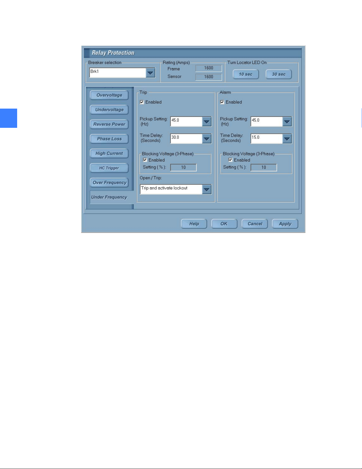
Figure 5-7 Settings for Under Frequency Relay
5
5.2.4.5 Usage
Event logging
While the relay is functional, the following events are logged for the under frequency relay in the
Entellisys CPU:
• Alarm Pickup Under Frequency – Alarm only under frequency relay has entered pickup.
• Alarm Under Frequency – Alarm only under frequency relay has operated.
• Alarm Dropout Under Frequency – Alarm only under frequency relay has dropped out of
pickup.
• Voltage Below Underfreq Alarm Blocking Voltage – The voltage has dropped below the alarm
only under frequency blocking voltage threshold.
• Voltage Above Underfreq Alarm Blocking Voltage – The voltage has exceeded the alarm only
under frequency blocking voltage threshold.
• Pickup Under Frequency – Under frequency relay has entered pickup.
• Breaker Trip Under Frequency – Under frequency relay has operated.
• Dropout Under Frequency – Under frequency relay has dropped out of pickup.
• Voltage Below Under Frequency Blocking Voltage – The voltage has dropped below the
under frequency blocking voltage threshold.
• Voltage Above Under Frequency Blocking Voltage – The voltage has exceeded the under
frequency blocking voltage threshold.
To view these events, click Sequence of Events on the Main Menu.
Single point functions78
Page 79

5.2.5 Phase Loss Relay protection
Phase Loss is an optional relay that is part of the voltage relay package. The Entellisys system
performs Phase Loss Relay Protection by comparing the negative-phase sequence voltage to
the nominal 1X value of the system voltage.
For example, in a 120-V wye system, nominal 1X is defined as 120-V phase to neutral. The
negative-phase sequence voltage for the phase-to-phase voltages is used regardless of PT
configuration (i.e., delta or wye). The negative-phase sequence voltage for line-to-line is
calculated as follows:
5
V ++=
1
()
3
2
aVVaV
1N
32
The parameters in these equations are defined as:
V
= negative phase sequence voltage
N
a = 1∠120
a2 = 1∠240
For ABC phase rotation, V1 = Vab, V2 = Vbc, V3 = V
For ACB phase rotation, V1 = Vab, V2 = Vca, V3 = V
o
o
ca
bc
The negative-phase sequence voltages are calculated for the fundamental (60 or 50 Hz)
component only.
The relay can be in three states:
• Pickup – If the negative-phase sequence voltage is more than the pickup set point, the relay
goes into pickup, and is said to enter Pickup state.
• Operate – If the relay stays in Pickup state for a specified pickup delay time, the system trips
the appropriate circuit breaker or activates an alarm, and the relay is said to be in Operate
state.
5.2.5.1 Accuracy
• Drop out – The relay drops out of pickup when the negative-phase sequence voltage drops
below 97% of the programmed threshold. The relay is said to be in Drop out state.
The phase loss pickup setting can be adjusted from 8% to 50% in increments of 1%. The phase
loss delay setting can be adjusted from 0.5 second to 600 seconds in increments of 0.5 seconds.
Blocking voltage option: An optional blocking voltage is provided and, if enabled, is 5%. The
phase loss relay function is not performed if Blocking Voltage is enabled and the voltage on all
phases is less than the blocking voltage, in which case the system logs an event. If the phase
loss relay goes into pickup, and the voltage subsequently drops below the blocking voltage, the
relay goes out of pickup and the delay is reset. It is possible to suspend the relay through
FlexLogic.
Pickup accuracy is ±4%. Trip time accuracy is ±0.1 seconds.
Single Point Relay protection 79
Page 80

5.2.5.2 Setup
To set the Trip and Alarm settings for the Phase Loss relay
1. On the Main Menu, click User Settings, and then select Relay Protection.
2. On the Relay Protection screen, choose the circuit breaker number from the drop-down
menu and click Phase Loss.
The remainder of this section discusses the relay parameters that can be set in the Phase Loss
section of the Relay Protection screen as shown in Figure 5-8.
5.2.5.3 Trip settings
5
Relay Enabled: Select Enabled to enable the relay.
Pickup: Adjust the phase loss pickup from 8% to 50% in increments of 1% from the Pickup
Setting drop-down menu.
Delay: Adjust the phase loss delay from 0.5 to 600 seconds in increments of 0.5 seconds from
the Time Delay drop-down menu.
Blocking Voltage Enabled: Select Enabled in the Blocking Voltage section to enable the
blocking voltage. If the option is enabled, the blocking voltage setting is 5% of the nominal
voltage.
Open Trip: Select the command issued when the relay operates from the Open Trip drop-down
menu. Options are Open and don't activate lockout and Trip and activate lockout.
5.2.5.4 Alarm settings
Relay Enabled: Select Enabled to enable the relay.
Pickup: Adjust the phase loss pickup from 8% to 50% in increments of 1% from the Pickup
Setting drop-down menu.
Delay: Adjust the phase loss delay from 0.5 to 600 seconds in increments of 0.5 seconds from
the Time Delay drop-down menu.
Blocking Voltage Enabled: Select Enabled in the Blocking Voltage section to enable the
blocking voltage. If the option is enabled, the blocking voltage setting is 5% of the nominal
voltage.
Open Trip: Select the command issued when the relay operates from the Open Trip drop-down
menu. Options are Open and don't activate lockout and Trip and activate lockout.
Single point functions80
Page 81

Figure 5-8 Phase Loss Relay settings
5
5.2.5.5 Usage
The phase rotation is set at the factory and cannot be changed by the user.
Phase Loss goes into pickup whenever the negative-phase sequence voltage is greater than the
pickup threshold set by the user. The Phase Loss Relay trips or sets off the alarm with the time
delay set by the user.
Event logging
The events generated by a Phase Loss Relay are:
• Alarm Pickup Phase Loss – Alarm only phase loss relay has entered pickup.
• Alarm Phase Loss – Alarm only phase loss relay has operated.
• Alarm Dropout Phase Loss – Alarm only phase loss relay has dropped out of pickup.
• Voltage Below Phase Loss Alarm Blocking Voltage – The voltages on all three phases have
dropped below the alarm only phase loss blocking voltage threshold.
• Voltage Above Phase Loss Alarm Blocking Voltage – The voltage on at least one of the three
phases has exceeded the alarm only phase loss blocking voltage threshold.
• Pickup Phase Loss – Phase loss relay has entered pickup.
• Breaker Trip Phase Loss – Phase loss relay has operated.
• Dropout Phase Loss – Phase loss relay has dropped out of pickup.
Single Point Relay protection 81
Page 82

• Voltage Below Phase Loss Blocking Voltage – The voltages on all three phases have dropped
below the phase loss blocking voltage threshold.
• Voltage Above Phase Loss Blocking Voltage – The voltage on at least one of the three phases
has exceeded the phase loss blocking voltage threshold.
To view these events, click Sequence of Events on the Main Menu.
5.2.6 Reverse Power Relay
The Entellisys system provides a Reverse Power Relay that prevents an open primary on a
5
transformer from back-feeding the magnetizing current. The system performs this function by
comparing the magnitude and direction of the power in each phase to the set point. If, on any
phase, the direction of the power is reversed and the magnitude of the power is greater than the
set point for the specified time delay, the system opens or trips the circuit breaker or activates
an alarm.
The relay can be in three states:
• Pickup – If the reverse power is more than the pickup set point, the relay goes into pickup,
and is said to enter Pickup state.
• Operate – If the relay stays in Pickup state for a specified pick up delay time, the system trips
the appropriate circuit breaker or activates an alarm, and the relay is said to be in Operate
state.
• Drop out – The relay drops out of pickup when the reverse power drops below 97% of the
The power reversal pickup setting can be adjusted from 10 to 990 kW, in steps of 10 kW. The
power reversal delay setting can be adjusted from 0.5 second to 600 seconds in increments of
0.5 seconds.
5.2.6.1 Accuracy
Pickup accuracy is ±4%. Trip time accuracy is ±0.5 seconds.
5.2.6.2 Setup
To set the Trip and Alarm settings for the Reverse Power Relay
1. On the Main Menu, click User Settings, and then select Relay Protection.
2. On the Relay Protection screen, choose the circuit breaker number from the drop-down
The remainder of this section discusses the relay parameters that can be set in the Reverse
Power section of the Relay Protection screen as shown in Figure 5-9.
5.2.6.3 Trip settings
Relay Enabled: Select Enabled to enable the relay.
programmed threshold. The relay is said to be in Drop out state.
menu and click Reverse Power.
Pickup: Adjust the reverse power pickup from 10 to 990kW in increments of 10kW from the
Pickup Setting drop-down menu.
Delay: Adjust the reverse power delay from 0.1 to 600 seconds in increments of 0.5 seconds
from the Time Delay drop-down menu.
Single point functions82
Page 83

Open Trip: Select the command issued when the relay operates from the Open Trip drop-down
menu. Options are Open and don't activate lockout and Trip and activate lockout.
5.2.6.4 Alarm settings
Relay Enabled: Select Enabled to enable the relay.
Pickup: Adjust the reverse power pickup from 10 to 990kW in increments of 10kW from the
Pickup Setting drop-down menu.
Delay: Adjust the reverse power delay from 0.1 to 600 seconds in increments of 0.5 seconds
from the Time Delay drop-down menu.
Open Trip: Select the command issued when the relay operates from the Open Trip drop-down
menu. Options are Open and don't activate lockout and Trip and activate lockout.
Figure 5-9 Reverse Power Relay settings
5
Single Point Relay protection 83
Page 84

5.2.6.5 Usage
The Reverse Power Relay goes into pickup whenever the direction of power, on any phase, is
reversed and the magnitude of the power is greater than the pickup threshold set by the user.
The Reverse Power Relay trips or sets off the alarm with the time delay set by the user.
Event logging
The following events are generated by the Reverse Power Relay:
• Alarm Pickup Reverse Power – Alarm only reverse power relay has entered pickup
• Alarm Reverse Power – Alarm only reverse power relay has operated
5
• Alarm Dropout Reverse Power – Alarm only reverse power relay has dropped out of pickup
• Pickup Reverse Power – Reverse power relay has entered pickup
• Breaker Trip Reverse Power – Reverse power relay has operated
• Dropout Reverse Power – Reverse power relay has dropped out of pickup
To view these events, click Sequence of Events on the Main Menu.
5.2.7 High Current Relay
The Entellisys system provides a High Current Relay. The system performs this function by
comparing each of the current phases to the programmed threshold. If any of the currents are
above the programmed threshold for more than the programmed delay, the system activates
an alarm. The High Current Relay cannot trip a circuit breaker.
5.2.7.1 Accuracy
5.2.7.2 Setup
The relay can be in three states:
• Pickup – If the current in any phase is more than the pickup set point, the relay goes into
pickup, and is said to enter Pickup state
• Operate – If the relay stays in pickup state for a specified pick up delay time, the system trips
the appropriate circuit breaker or activates an alarm, and the relay is said to be in Operate
state
• Drop out – The relay drops out of pickup when the current drops below 97% of the
programmed threshold. The relay is said to be in Drop out state.
The high current pickup relay can be adjusted from 50% to 200% of the Long Time Protection
pickup setting, in increments of 5%. The high current delay setting can be adjusted from 1 to 15
seconds in steps of 1 second. The relay can be suspended through Flex Logic.
Pickup accuracy is ±10%. Trip time accuracy is ±1 second.
To set the Alarm settings for the high current relay
1. On the Main Menu, click User Settings, and then select Relay Protection.
2. On the Relay Protection screen, choose the circuit breaker number from the drop-down
menu and click High Current.
The remainder of this section discusses the relay parameters that can be set in the High Current
section of the Relay Protection screen as shown in Figure 5-10.
Single point functions84
Page 85

5.2.7.3 Alarm settings
Relay Enabled: Select Enabled to enable the relay.
Pickup: Adjust the high current pickup from 50% to 200% in increments of 5% from the Pickup
Setting drop-down menu.
Delay: Adjust the high current delay from 1 to 15 seconds in increments of 1 second from the
Time Delay drop-down menu.
Figure 5-10 High Current Relay settings
5
5.2.7.4 Usage
The High Current Relay goes into pickup when any of the currents are greater than the
programmed threshold. The high current relay sets off the alarm with the time delay set by the
user.
5.2.7.5 Event logging
The High Current Relay generates the following events:
• Alarm Pickup High Current – High current relay has entered pickup
• Alarm High Current – High current relay has operated
• Alarm Dropout High Current – High current relay has dropped out of pickup
To view these events, click Sequence of Events on the Main Menu.
Single Point Relay protection 85
Page 86

5.2.8 High Resistance Ground Fault Detection Relay
The Entellisys system provides an optional High Resistance Ground Fault Detection (HRGF)
Function that is an alarm-only function that does not trip the circuit breaker. The relay requires
an additional 10A ground CT and will detect a fault by measuring the current through the
resistance ground circuit of the substation transformer.
The system will indicate that a ground fault event occurred and on which phase. See High
Resistance Ground Fault Location Relay on page 88 to locate the specific feeder.
5
The relay can be in three states:
• Pickup – If the ground current in any phase is more than the pickup set point, the relay goes
into pickup, and is said to enter Pickup state.
• Operate – If the relay stays in pickup state for a specified pick up delay time, the system
activates an alarm, and the relay is said to be in Operate state.
• Drop out – The relay drops out of pickup when the ground current drops below 97% of the
programmed threshold. The relay is said to be in Drop out state.
The HRGF pickup is programmable from 0.1 amps to 10.0 amps of ground current in increments
of 0.1 amps. The delay setting is programmable from 0.5 to 5 seconds in increments of
0.1 second. A constant time curve is used for HRGF. If the ground current is above the pickup
threshold, the system logs an event. If the ground current remains above the threshold for
longer than the delay setting, the system logs an event and activates an alarm.
NOTE: Multi-Source Ground Fault is not available in High Resistance Systems
5.2.8.1 Accuracy
Pickup accuracy is ±10%. For 1 Amp and below, the accuracy is ± 10% of 1 Amp
5.2.8.2 Setup
The HRGF relay is a per line-up option.
To set the Alarm settings for the HRGF relay
1. On the Main Menu, click User Settings, and then select Advanced Protection.
2. On the High Resistance GF tab (User Settings, Advanced Protection screen), choose the
circuit breaker number from the drop-down menu and click High Resistance GF.
The remainder of this section discusses the relay parameters that can be set in the High
Resistance GF section of the Relay Protection screen as shown in Figure 5-11.
NOTE: High Resistance Detection and Location Relays are only available on breakers which
have a ground CT.
5.2.8.3 Alarm settings
Relay Enabled: Select Enabled to enable the relay.
Single point functions86
Page 87

Pickup: Adjust the HRGF pickup from 0.1 Amps to 10 Amps in increments of 0.1 Amp from the
Pickup Setting drop-down menu.
Delay: Adjust the HRGF delay from 0.5 to 5 seconds in increments of 0.1 second from the Time
Delay drop-down menu.
Ground Resistance: Enter the untapped system ground resistance from 5 to 500 ohms in
increments of 1 ohm.
Figure 5-11 High Resistance GF settings
5
5.2.8.4 Usage
The High Resistance Ground Fault Relay goes into pickup if the ground current is above the
pickup threshold and generates an alarm if the ground current remains above the threshold for
longer than the delay setting.
5.2.8.5 Event logging
The HRGF relay generates the following events:
• Pickup High Resistance GF – when the alarm function enters pickup
• Alarm High Resistance GF – when the alarm function operates
• Drop out High Resistance GF – when the alarm function drops out
To view these events, click Sequence of Events on the Main Menu.
Single Point Relay protection 87
Page 88

5.2.9 High Resistance Ground Fault Location Relay
The Entellisys system provides High Resistance Ground Fault Location (HRGF Location) for up to
4 mains which locates a fault by analyzing system currents while operating the ground resistor
pulsing contactor.
For example, in a typical High Resistance system, a phase to ground fault will be limited to 5-15
Amps allowing the breaker to remain closed. To locate, a ground contactor will short some of
the resistor effectively reducing the ground resistance and increasing the ground current at a
periodic rate. Location systems will use this amperage modulation to locate the fault to the
5
specific breaker(s) affected.
Unlike traditional systems, Entellisys does not require additional sensors to locate a ground
fault, rather it utilizes a signal processing algorithm to detect the low magnitude ground signal
in the presence of large phase currents. Entellisys then reports all breakers that are seeing the
modulated current - including mains and ties.
Highlights
Manual Mode will pulse the contactor indefinitely until stopped by the user.
Tripping Option: When a ground fault occurs and has been successfully located, the relay
will begin timing to trip the faulted breaker. If the fault continued uninterrupted for the
specified number of hours, the feeder breakers reported by this function will be tripped.
Tripping Priority: If a breaker faults to ground while a HR fault already exists there will be
what amounts to a phase to phase fault through ground. In High Resistance systems, only
one breaker needs to be tripped. Entellisys allows the user to configure a tripping priority to
each breaker. (See Ground Fault Tripping priority
Operation
the location relay can be set to automatically operate when a fault is detected. Once the
detection relay is in pickup, the location relay automatically starts to locate the fault by pulsing
the grounding contactor through the discrete I/O for 1 minute.
The CPU locates the ground fault by creating a tracing signal in the ground current using a
pulsing contactor toggled by a Flex Logic contact output “HRGF Pulse contactor output 1-4”
routed to an appropriate discrete output to pulse the contactor.
When the contactor is ON, the resistance value will be lowered and the ground current will be
increased, thus creating a tracing pulse current through the ground resistor. Only one contactor
among of the available contactors (maximum of 4) will be operating at any point of time. The
contactor pulsing can be manually initiated under any condition.
The pulsing contactor connected to the discrete I/O must have a coil current less than 1 Ampere
of 120VAC current when closed. The contact ratings must be at least 10A @ 600VAC when
closed and while opening.
The user must go to the Event screen to view the results of the HRGF location relay. From the
HRGF events, the user will be able to determine that a ground fault has occurred and if the
system has located the responsible feeder. There are also several alarms to help alert the user.
(See Events and Alarms
on page 94)
on page 126)
Single point functions88
Page 89

Operational limitations
Location may not find the faulted feeder under the following conditions:
• Load Currents above 1X (Overload)
• High Z fault (insufficient pulse current)
• Multiple feeders faulted
• Other rapid transient currents (i.e. motors starting every fraction of a second)
• Network (parallel) applications may not locate for mains and ties
• Minimum pulse current not met
• Breaker is in a reverse power condition
Figure 5-12 HRGF Detection and Location process - w/ optional trip enabled
5
5.2.9.1 Hardware Requirements
The system must be a High Resistance grounded system with HRGF detection and have either
redundant or non-redundant discrete I/O
Single Point Relay protection 89
Page 90

5.2.9.2 Accuracy
The location relay is dependant on the CT size and differential current between the pulsing
contactor’s on and off state. The minimum differential pulse current will, in turn, depend on fault
impedance and the size of the grounding resistors.
Table 5-8 CT accuracy in terms of detectable fault currents
CT Rating (Amps) Minimum detectable
differential current
(Differential amps)
5
150 1.0
400 1.0
800 1.0
1,600 1.0
2,000 1.2
3,200 1.5
4,000 2.0
5,000 3.0
Single point functions90
Page 91

5.2.9.3 Setup
The HRGF Location functionality is an extension to the HRGF Detection relay. Since the location
process starts after a fault has been detected by HRGF Detection, the configuration parameters
specified for the HRGF Detection functionality must be set for the feature to work.
The High Resistance Detection and Location Relays are only available on breakers which have a
ground CT installed by the factory. To navigate to the setup screen login as an administrator to
the HMI and open the Advanced Protection (Main Menu, User Settings)
Figure 5-13 High Resistance GF Location settings
5
Select Breaker With Ground CT - Lists only breakers with ground CT’s assigned to them from
the factory
HRGF Location Function: Lists the available location relays - if optioned. Typically will reflect the
number of mains in the system equipped with HR equipment.
Detection Function: See Setup
Location Relay Group box
Contactor Frequency: (0.5 - 2 Hz or 30 - 120 pulses per minute) Frequency at which the
contactor will pulse. User can adjust depending on the sensitivity of hand held amp meters
used to locate the fault downstream of Entellisys.
on page 86
Single Point Relay protection 91
Page 92

Location Subinterval: (20-60 seconds, default 30) defines the minimum duration of pulsing
required before initiating a location event.
Start Automatic Location: Default checked - starts location automatically after a fault is
detected.
Trip group box
Time Delay: (0 to 999 hr in 1 hr increments, 0 will trip immediately) Time the system will wait
before issuing a trip command to a feeder. Note: Only available for feeders.
Alarm Settings group box
5
Re-Alarming Time Delay: (0 to 99 hr in 1 hr increments, 0 is disabled) Turns the
acknowledged alarm back to un-acknowledged (blinking) and logs a single event.
Alarm Re-Check Time Delay: 0 to 99 hr in 1 hr increments0 is disabled) Logs event every
interval only after re-alarm if fault still exists. Does not change the fault alarm acknowledge
state.
5.2.9.4 Tripping
Once a fault has been detected and located, the trip timer will begin timing only on breakers
classified as feeders. Once the trip timer times out, the faulted feeder will only trip after the
location relay verifies that it is still faulted by re-running the location routine.
If, before the breaker is tripped, the detection relay drops out then the system will wait for up to
30 seconds before resetting the trip timer. If the fault reoccurs within 30 seconds, the trip timer
will continue timing.
While timing out, if the located breaker is opened and the detection drops out then the function
is reset. If detection does not drop out then locate will find and restart timing for a new faulted
breaker.
Lastly, if the detection relay is still active but the fault originally located is not verified by the
system, the system will attempt 10 times to locate the breaker every 30 minutes or until the
detection relay drops out. If the location verification identifies a different faulted breaker, trip
timing will be restarted for the newly faulted breaker.
The system will only trip a breaker if the following conditions are met
• The breaker has been designated as a feeder (factory configuration)
• Location trip has been enabled
• Trip timer has timed out
• The location function has verified that the breaker is still faulted
If the Trip Time Delay is set to 0, then the location verification and retry attempts will occur
immediately without the 30 minute delay and immediately trip the breaker after location
verification.
How to determine if a breaker is configured to trip:
1. Login to the HMI as an administrator and navigate to the Maintenance screen
2. Select the “Zone Configuration” tab
3. Select the High Resistance GF button - See Figure 5-14
Single point functions92
Page 93

To modify the breaker list, contact GE Post Sales Service. See How to contact us on page 2
NOTE: Once a breaker is tripped, a ground fault may still exist. The fault could still be present
because there is a second, higher impedance fault that was masked by the first fault.
Figure 5-14 List of HRGF Location breakers configured to trip
5
Single Point Relay protection 93
Page 94

5.2.9.5 Manual Mode
5
Entellisys provides the ability to manually pulse the contactor either for testing purposes or to
locate the fault downstream of Entellisys. When the location function is started manually, the
location relay will attempt to locate the feeder and continue to pulse the contactor until the time
it is stopped by the user.
To place the HRGF Location in manual mode, click on the HRGF Location button from the
Events screen.
To Start, wait until automatic mode is idle and choose the function (if more than one function is
enabled) and click start or stop. The contactor will begin pulsing indefinitely.
After initiating the manual mode, the screen may be closed and the contactor will continue to
pulse. Return to the Manual Mode to stop the contactor pulsing.
Figure 5-15 HRGF Location manual mode screen
5.2.9.6 Events and Alarms
Events
Start and Stop events: Each location relay will log an event when HRGF is started and
stopped either automatically or manually.
Location Events: Upon location of the ground fault, the CPU will log an event listing the
name of the located feeder breakers
Trip events: An event is logged when the Location Relay is in pickup, dropout or trips the
feeder breaker with the ground fault
Alarms
The CPU provides the following alarm functionality for the HRGF Location feature, irrespective of
the fault being located by either automatic or manual mode:
The High Resistance GF Location Alarm will activate the alarm upon location of the ground
fault. The alarm, if acknowledged, will return to an un-acknowledged state if the fault is not
cleared before the re-alarming delay or recheck delay.
The Trip Alarm will alarm when the HRGF Location relay issues a trip command.
Single point functions94
Page 95

Contactor Pulsing Alarm is provided to alert the user that the contactor is actively being
pulsed by Entellisys - either manually or automatically.
5.3 Synch Check relay
The Synch Check function is used as a permissive for closed-transition automatic throw-over
control schemes.
Entellisys performs the synch check relay function by comparing the amplitude, phase and
frequency of the voltages in each of the three phases of the two selected source circuit
breakers.
NOTE: The Synch Check Relay function is not a per messenger option, but a per line up option.
Entellisys provides up to six synch check functions.
The following thresholds are used by the Synch Check relay:
Dead Bus Threshold: This user-programmable value represents the voltage for source 1 below
which a phase is considered dead.
5
Live Bus Threshold: This user-programmable value represents the voltage for source 1 above
which a phase is considered live.
5.3.1 Synch check status
Each synch check function provides the following status information:
Synchronous Live: Set to true if all three phases at both sources are above the live bus
threshold and are in synch (i.e., all three phases satisfy the programmed voltage, frequency, and
phase differential criteria) and is set to false otherwise.
Dead Source: If one or both sources are de-energized, the dead source selection permits closing
of the circuit breaker to by-pass the synch check measurements. The following Dead Source
criteria selections are available:
• None – Dead source function is disabled
• LV1 and DV2 – Voltage source 1 live and voltage source 2 dead
• DV1 and LV2 – Voltage source 1 dead and voltage source 2 live
• DV1 or DV2 – Voltage source 1 dead or voltage source 2 dead
• DV1 xor DV2 – One voltage source is dead, the other is live
• DV1 and DV2 – Both sources are dead
The Dead Source status is shown as true if the programmed dead bus configuration condition is
true.
Close: This status is set to true if Synchronous Live is true or Dead Source is true.
Synch Check relay 95
Page 96

Each synch check function verifies that the two sources have the same PT primary voltage and
5
configuration (delta or wye). If both parameters are not the same for both sources, the CPU logs
an event and disables the synch check function.
5.3.2 Setup
To set the settings for the Synch Check Relay
1. On the Main Menu, click User Settings, and then select Control.
2. On the Control screen, click Synch Check.
The remainder of this section discusses the parameters that can be set in the Synch Check
section of the Control screen as shown in Figure 5-16.
The following settings must be set for the Synch Check Relay:
Synch Check Function: Choose the synch check relay number from the Synch Check Function
drop-down menu.
Relay Name: Assign a name for identifying the relay.
Relay Enabled: Select Enable to enable the relay.
5.3.2.1 Source voltages
First: Select the circuit breaker number that provides the voltage for source 1 from the First
drop-down menu in the Source Voltages menu group.
Second: Select the circuit breaker number that provides the voltage for source 2 from the
Second drop-down menu in the Source Voltages menu group.
5.3.2.2 Maximum differentials
Voltage: Adjust the maximum voltage differential allowed between source voltages for the
synch check function to operate from 0 to 90 V in steps of 0.5 V from the Voltage drop-down
menu in the Maximum Differentials menu group.
Frequency: Adjust the maximum frequency differential allowed between source voltages for the
synch check function to operate from 0 to 2 Hz in steps of 0.1 Hz from the Frequency
drop-down menu.
Phase: Adjust the maximum phase differential allowed between source voltages for the synch
check function to operate from 0 to 60 degrees in steps of 1 degree from the Phase drop-down
menu.
The Synch Check function applies a 3% hysteresis factor to the voltage, frequency, phase, live
bus and dead bus thresholds.
5.3.2.3 Source 1
Dead Bus Threshold: Adjust the threshold below which a phase is considered dead from 5 to
50% of the nominal voltage (line-neutral for wyes, line-line for deltas) in steps of 1% from the
Dead Bus Threshold drop-down menu in the Source 1 menu group.
Single point functions96
Page 97

Live Bus Threshold: Adjust the threshold above which a phase is considered live from 50% to
100% of the nominal voltage (i.e., the PT rating, line-neutral for wyes, line-line for deltas) in steps
of 1% from the Live Bus Threshold drop-down menu in the Source 1 menu group.
5.3.2.4 Source 2
Dead Bus Threshold: Adjust the threshold below which a phase is considered dead from 5 to
50% of the nominal voltage (line-neutral for wyes, line-line for deltas) in steps of 1% from the
Dead Bus Threshold drop-down menu in the Source 2 menu group.
Live Bus Threshold: Adjust the threshold above which a phase is considered live from 50% to
100% of the nominal voltage (i.e., the PT rating, line-neutral for wyes, line-line for deltas) in steps
of 1% from the Live Bus Threshold drop-down menu in the Source 2menu group.
5.3.2.5 Configuration
Select the condition under which the “Dead Source” status output is true from the following
options in the Configuration drop-down menu:
• None – Dead source function is disabled
• LV1 and DV2 – Voltage source 1 live and voltage source 2 dead
• DV1 and LV2 – Voltage source 1 dead and voltage source 2 live
• DV1 or DV2 – Voltage source 1 dead or voltage source 2 dead
5
• DV1 xor DV2 – One voltage source is dead, the other is live
• DV1 and DV2 – Both sources are dead
NOTE: A source is considered dead when all voltage phases are below the dead bus threshold.
A source is considered live when all voltage phases are above the live bus threshold.
Figure 5-16 Settings for Synch Check Relay
Synch Check relay 97
Page 98

5
5.3.3 Usage
When two voltage source circuit breakers are selected as the two sources for synch check relay,
if the differences in their magnitude, phase and frequency are within the set limits, the synch
check shows the synch status as Live and Synchronized. The Dead Source status is also shown
depending on whether the selected criterion for the dead source is met .
Figure 5-17 shows the status of a typical Synch Check Relay.
Figure 5-17 Synch Check status
Single point functions98
Page 99

5.3.3.1 Event logging
The following events are logged for the Synch Check relay:
• Synch Check Control Enabled 1…12 – Synch check relay 1…12 has been enabled
• Synch Check Control Disabled 1…12 – Synch check relay 1…12 has been disabled
• Synch Check 1…12 Sources Not Synchronized – Messengers that are providing voltage
information for synch check relay are not synchronized, so Entellisys is unable to check for
synchronization between voltage sources.
• Synch Check 1…12 Sources Not Compatible – Voltage sources for synch check relay 1…12 are
not compatible; i.e. they have different PT configurations or ratings
• Synch Check 1…12 Dead Source Operate – Dead source criteria for synch check relay 1…12
have been met
• Synch Check 1…12 Dead Source Drop Out – Dead source criteria for synch check relay 1…12
have been met
• Synch Check 1…12 V1 Above Minimum – Voltage source 1 for synch check relay 1…12 is
above the live source threshold
• Synch Check 1…12 V1 Below Maximum – Voltage source 1 for synch check relay 1…12 is
below the dead source threshold
• Synch Check 1…12 V2 Above Minimum – Voltage source 2 for synch check relay 1…12 is
above the live source threshold
5
• Synch Check 1…12 V2 Below Maximum – Voltage source 2 for synch check relay 1…12 is
below the dead source threshold
To view these events, click Sequence of Events on the Main Menu.
Synch Check relay 99
Page 100

5
Single point functions100
 Loading...