

Page 1
GE Industrial
Solutions
EntelliPro ES Motor Controller
Installation and Instruction Manual
EntelliPro ES Revision: 3.0
Manual Part Number: GEH-6000
Copyright©
2011 GE Industrial Solutions
Page 2

This page was intentionally left blank
Page 3

GE Industrial Solutions
Table of Contents
Chapter 1: Introduction
1.1 Overview ..................................................................................................................................... .............................................................. .. 1.1
1.1.1 Warnings, cautions, notes, and references............................................................................................................... 1.2
1.1.2 Definitions.................................................................................................................................................................. .............. 1.3
1.1.3 Description of the EntelliPro ES Motor Control Module ........................................................................................ 1.4
1.1.4 EntelliPro ES order code ................................................................................................................................................... .. 1.6
1.1.5 EntelliPro ES Current Transformer Definition ............................................................................................................ 1.8
1.2 Specifications ................................................................................................................................................. ........................................... 1.9
1.2.1 Protection Specifications ........................................................................................................................................... ........ 1.9
1.2.2 Metering and monitoring specifications ..................................................................................................................... 1.10
1.2.3 Input specification ................................................................................................................................................................ 1.10
1.2.4 Output specifications .......................................................................................................................................................... 1.12
1.2.5 Power supply specifications ............................................................................................................................................. 1.13
1.2.6 Communication specifications........................................................................................................................................ 1.13
1.2.7 Testing and certification .................................................................................................................................................... 1.14
1.2.8 Approvals .................................................................................................................................................................................. 1.15
1.2.9 Physical specifications ........................................................................................................................................................ 1.15
1.2.10 Environmental specifications........................................................................................................................................... 1.14
1.3 EntelliPro CP3/CP5 HMI ......................................................................................................................................................................... 1.16
1.4 WinESG Configuration Tool ................................................................................................................................................................. 1.17
Chapter 2: Installation / Configuration
2.1 Installation and initial operating ................................................................................................................................. ...................... 2.1
2.1.1 Mechanical installation................................................................................................................................... .................... 2.2
2.1.1.1 Dimensions................................................................................................................... ...................................... 2.2
2.1.1.2 Product
identification ......................................................................................................................................
2.1.1.2.1 Label Definition......................................................................................................... ................. 2.3
2.1.1.3 Mounting ................................................................................................................................ ............................. 2.4
2.1.1.4 EntelliPro ES Connector terminal
EP OS MOTOR MANAGEMENT SY STEM – INSTRUCTION MANUAL
identification ...................................................................................
2.3
2.5
Page 4

TABLE O F CO NTENTS
2.1.2 Electrical installation............................................................................................................................... ................................. 2.6
2.1.2.1 Power supply connection ................................................................................................................................ 2.6
2.1.2.2 Communication connection ........................................................................................................................... 2.7
2.1.2.3 Thermistor connection ..................................................................................................... ................................. 2.7
2.1.2.4 Phase Current Connection .............................................................................................................................. 2.8
2.1.2.5 Input/output connection ............................................................................................................. ..................... 2.8
2.1.2.6 4-20mA output connection............................................................................................................................ 2.9
2.1.2.7 Dielectric strength testing ............................................................................................................................... 2.9
2.2 Motor Control Configuration ................................................................................................................................................................... 2.10
2.2.1 Motor Control Detailed Configuration.............................................................................................................................. 2.10
2.2.1.1 Local and remote sources listing.................................................................................................................. 2.11
2.2.1.1 Input configuration ………………………................................................................................................................. 2.11
2.2.1.3 Motor Control via Modbus configuration................................................................................................... 2.11
2.2.1.4 Motor Control via WinESG .............................................................................................................................. 2.13
2.2.1.5 Motor Control via Profibus Class 1.............................................................................................................. 2.13
2.2.1.6 ATEX Configuration ............................................................................................................................................2.13
2.2.2 Motor Control Pre-Programmed Configuration ......................................... .................................................................. 2.13
Control Variant 1 Configuration.......................................................................................................................................... 2.14
Control Variant 2 Configuration.......................................................................................................................................... 2.15
Control Variant 3 Configuration.......................................................................................................................................... 2.16
Control Variant 4 Configuration.......................................................................................................................................... 2.17
Control Variant 5 Configuration.......................................................................................................................................... 2.18
Control Variant 6 Configuration.......................................................................................................................................... 2.19
2.3 Motor Starter Configuration.................................................................................................................................................................... 2.20
2.3.1 Motor Starter Type - Full-voltage non-reversing starter ......................................................................................... 2.21
2.3.2 Motor Starter Type - Full-voltage reversing starter ................................................................................................... 2.26
2.3.3 Motor Starter Type - Star-delta open transition starter.......................................................................................... 2.31
2.3.4 Motor Starter Type - Star-delta reverse open transition starter .......................................................................... 2.36
2.3.5 Motor Starter Type – Soft starter
2.3.6 Motor Starter Type - Reverse Soft starter
type
............................................................................................................................. 2.40
type
.................................................... ........................................................ 2.45
2.3.7 Breaker Control .......................................................................................................................................................................... 2.51
2.3.9 Motor Starter Type – Pole changer starter
2.3.8 Motor Starter Type - Dahlander starter
2.3.10 Solenoid valve
2.3.11 Actuator
type....................................................................................................................................................................
type
.............................................................................................................................................................................. 2.72
type
.................................................... ............................................................ 2.56
type
.................................................. ........................................................ 2.61
2.66
Page 5

TAB L E OF CO N T E NTS
Chapter 3: Motor Protection
3.1 Thermal Ov
3.1.1 Unbalance and phase-loss biasing............................................................................................. ..................................... 3.2
3.1.2 Hot/cold biasing ........................................................................................................................................................ ............... 3.2
3.1.3 Overload curve ........................................................................................................................................................ .................. 3.3
3.1.4 Cooling rate ............................................................................................................................................ .................................... 3.6
3.1.5 Overload protection n-times reset .................................................................................................................................. 3.15
3.1.6 Overload protection programmable settings............................................................................................................. 3.17
3.2 Phase loss and current unbalance .................................................................................................................................................... 3.19
3.3 Ground fault ................................................................................................................................................................................................. 3.20
3.4 Overcurrent and stalled rotor protection ........................................................................................................................................ 3.21
3.5 Undercurrent protection......................................................................................................................................................................... 3.23
3.6 Thermistor (TMA)......................................................................................................................................................................................... 3.25
Chapter 4: Communication
4.1 Modbus RTU .................................................................................................................................................... .............................................. 4.1
4.1.1 Modbus address setting ................................................................................................................................ ........................ 4.1
4.1.2 Modbus baud rate and port configuration ........................................................ ................................................ ........... 4.3
4.1.3 Modbus function
4.1.4 Modbus topology.................................................................................................................................. .................................... 4.5
4.1.5 RS-485 connections ............................................................................................................................................... ................. 4.6
4.1.6 RS-485 termination
4.1.7 Grounding shielding
4.1.8 Implementation basics .......................................................................................................................................... ................ 4.7
4.1.9 Modbus RTU message format ................................................................................................... ......................................... 4.7
4.1.10 EntelliPro ES Function
4.1.11 Error Responses ....................................................................................................................................................................... 4.16
4.1.12 Modbus Register Map............................................................................................................................................................ 4.17
erload
...................................................... ........................................................................ ......................................................... 3.1
codes
...................................................... ........................................................................ ........................... 4.4
considerations ...................................................................................................................................
considerations
Code
..................................................................................................................................... ............ 4.8
.................................................... .................................................................... ........ 4.6
4.6
4.1.10.1 Function code 03H............................................................................................................................... .............. 4.8
4.1.10.2 Function Code 04H ........................................................................................................ .................................... 4.9
4.1.10.3 Function Code 05H ........................................................................................................ .................................... 4.10
4.1.10.4 Function Code 06H ........................................................................................................................................... 4.13
4.1.10.5 Function Code 10H ........................................................................................................................................... 4.14
4.1.10.6 Function Code 14H ........................................................................................................................................... 4.15
4.1.10.7 Function Code 15H ........................................................................................................................................... 4.15
EP OS MOTOR MANAGEMENT SYSTEM – INSTRUCTION MANUAL
Page 6

TABLE O F CO NTENTS
4.2 Profibu s ....................................................................................................................................................................................................... 4.33
4.2.1 Definitions................................................................................................................................................................................ 4.33
4.2.2 Profibus System concept .................................................................................................................................................. 4.34
4.2.3 Profibus Interface................................................................................................................................................................. 4.35
4.2.4 Profibus termination............................................................................................................................................................ 4.36
4.2.5 Profibus DP-parameterization ........................................................................................................................................ 4.36
4.2.6 Communication set up and station
4.2.7 Profibus DP Cyclic Data ..................................................................................................................................................... 4.37
4.2.8 Profibus DP Cyclic Data .................................................................................................................................................... 4.48
4.2.9 Diagnostic Data .................................................................................................................................................................... 4.48
4.2.10 Profibus Protocol communication set-up.................................................................................................................. 4.50
4.2.7.1 EntelliPro ES Cyclic Read Telegram Definitions .................................................................................. 4.38
4.2.7.3 EntelliPro ES Cyclic Write Telegram Definitions.................................................................................. 4.46
addr
esses ............................................ ........................................................... 4.36
Chapter 5: WinESG
4.2.11 Profibus-DP Class1 Parameterizing ..............................................................................................................................4.53
5.1 File menu ...................................................................................................................................... .................................................................. 5.4
5.1.1 Win ESG Configuration ........................................................................................................................................................ .. 5.5
5.1.2 Slave Device Configuration ................................................................................................. ................................................ 5.6
5.2 Options Menu ................................................................................................................................................. .............................................. 5.7
5.2.1 Alarm protocol panel.............................................................................................................................................................. 5.7
5.2.2 Access protection panel……. ................................................................................................................................................ 5.8
5.2.3 Alarm panel………………………. .................................................................................................................................................... 5.9
5.2.4 Time synchronization panel................................................................................................................................................ 5.9
5.2.5 Read all Parameters…………… ................................................................................................................................................ 5.9
5.2.3 Send all Parameters ……………………….................................................................................................................................... 5.9
5.3 Windows menu .............................................................................................................................................................. ............................. 5.10
5.3.1 Control Panel ............................................................................................................................... .............................................. 5.10
5.3.2 Parameterization........................................................................................................................................ ............................. 5.12
5.3.2.1 Info panel .................................................................................................................................................... ......... 5.12
5.3.2.2 Device Setting panel ........................................................................................................................................ 5.14
5.3.2.3 Alarms panel ..................................................................................................................................................... 5.18
5.3.2.4 Function panel .................................................................................................................................................... 5.19
.
5.3.2.5 Timer panel .......................................................................................................................................................... 5.20
5.3.2.6 Counter panel ................................................................................................................................................... 5.21
5.3.2.7 Control panel ...................................................................................................................................................... 5.21
5.3.2.8 Typical settings panel ...................................................................................................................................... 5.23
5.3.2.9 I/O’s panel ............................................................................................................................................................ 5.25
5.3.2.10 Cyclic panel .......................................................................................................................................................... 5.26
Page 7

TAB L E OF CO N T E NTS
5.3.2.11 Modbus setting panel ..................................................................................................................................... 5.26
5.3.2.12 Char (Characteristic) panel ........................................................................................................................... 5.27
5.3.2.13 Diagnostic panel ................................................................................................................................................ 5.27
5.3.2.14 Measure panel .................................................................................................................................................... 5.27
5.3.2.15 Alarm panel.......................................................................................................................................................... 5.28
5.3.3 Debug panel ............................................................................................................................................................................. 5.28
5.4 Tools menu ................................................................................................................................................................ ................................... 5.37
5.4.1 Event protocol
5.4.2 Analog data panel..................................................................................................................................... .............................. 5.38
......
.....
..................
.................
...............................
.................................... ..........................
................
5.4.3 Flexible logic download................................................................................................................ ......................................... 5.39
Chapter 6: EntelliPro CP3 and CP5
6.1 EntelliPro CP3 main panel............................................................................................................................................................................. 6.1
6.2 EntelliPro CP3 application setting.............................................................................................................................................................. 6.6
6.3 EntelliPro CP3 screen saver display......................................................................................................................................................... 6.8
............... 5.37
6.4 EntelliPro CP3 application tree structure
6.5 EntelliPro CP5 main panel
...............................................................................................................................................
............................................................................................................................................... 6.9
......................
6.6 EntelliPro CP5 application setting......................................................................................................................................................... 6.13
6.7 EntelliPro CP5
6.8 EntelliPro CP5 device screen
6.
9 EntelliPro CP5 control screen
device addresses......................................................................................................................................................
....................................................................................................................................................
............... 6.15
..................................................................................................................................................................
6.10 EntelliPro CP5 screen saver display..................................................................................................................................................... 6.17
EntelliPro CP5 installation........................................................................................................................................................................ 6.18
6.11
6.12 EntelliPro CP5 application tree structure.......................................................................................................................................... 6.19
Chapter 7: Revision / Service / Sales
Revision........................................................................................................................................ ................................................................................ ... 7.1
Service for Low voltage equipment ………………………… .................................................................................... ................................................. 7.2
Sales ................................................... .............................................................. ............................... ................................................................................. 7.5
.... 6.11
...... 6.14
6.16
EP OS MOTOR MANAGEMENT SYSTEM – INSTRUCTION MANUAL
Page 8

This page was intentionally left blank
Page 9

CHAPTER 1: INTR ODUCTION
GE Industrial
Solutions
EPOS Motor Management System
Chapter 1: Introduction
This chapter provides an overview of the EPOS Motor Control System. Additional details are provided in subsequent
chapters.
1.1 Overview
The EPOS Electronics Protection and Object Control System is a motor protection system designed specifically
for low-voltage motor applications. It is comprised of the following modules:
EntelliPro ES: a modular control unit that represents the lowest level in the control
The EntelliPro ES can be programmed as an EntelliPro ES retrofit, where the Profibus telegrams match the ESS
DP device. Alternatively, the EntelliPro ES can be programmed as a non-retrofit unit, where additional Profibus
telegrams are made available.
The EntelliPro ES provides the following key features:
EP OS MOTOR MANAGEMENT SYSTEM – INSTRUCTION MANUAL 1.1
hierarchy of the EPOS system.
EntelliPro CT: a current transformer that is used in conjunction with EntelliPro
ES in a branch-drawout system.
WinESG: a Profibus base programmable software used to configure EntelliPro ES Alarm
handling, read and write parameters.
Optional EntelliPro CP3 or EntelliPro CP5: Modbus-based HMI (human-machine interface). One
HMI is provided as part of the MCC package and is programmed to display metering and other
parameters. Refer to chapter 6 for additional information.
Flexible protection, control, and communication options to suit any low-voltage motor
application.
Small footprint designed specifically for IEC and NEMA MCC applications.
Modular
DIN rail mounting.
Dual, simultaneous communication protocols (Modbus and Profibus) allow simple integration into
monitoring and control systems.
Multiple inputs and outputs.
Eleven pre-programmed motor starter types.
Programmable custom motor starter logic for complex systems.
design reduces the number of spare components for maintenance and testing.
Page 10

CHAPTER 1: INTR ODUCTION
1.1.1 Warnings, cautions, notes, and references
WAR NI NG notices are used in this publication to emphasize that hazardous voltages, currents, or other conditions
that could cause personal injury exist in this equipment or may be associated with its use. Warning notices are also
used for situations in which inattention or lack of equipment knowledge could cause either personal injury or damage
to equipment.
CAUTION notices are used for situations in which equipment might be damaged if care is not taken.
NOTES call attention to information that is especially significant to understanding and operating the equipment . This
document is based on information available at the time of its publication. While efforts have been made to ensure
accuracy, the information contained herein does not cover all details or variations in hardware and software, nor
does it provide for every possible
may be described herein that are not present in all hardware and software systems. GE Industrial Solutions assumes
no obligation of notice to holders of this document with respect to changes
ATEX sign is used to indicate mandatory settings and items for use of EntelliPro to protect motors in in potential
explosive environment.
contingency
in connection with installation, operation, and maintenance. Features
subsequently
made.
GE Industrial Solutions makes no representation or warranty, expressed, implied, or statutory, with respect to, and
assumes no
herein. No warrantees of merchantability or fitness for purpose shall apply.
responsibility
for the accuracy, completeness, sufficiency, or usefulness of the information contained
References
For details of the Modbus RTU protocol, refer to PI-MBUS-300 Rev. J from Modicon/AEG Schneider Automation. For
details of RS-485 communications, refer to the EIA-485 standard.
Modbus RTU® is a registered trademark of AEG Schneider Automation. Modbus® is a registered trademark of
Modicon Inc.
For additional information on the EntelliPro CP3 and CP5 HMI, please refer to the Beijer Electronics H-T40 and H-T70
installation and operation manuals.
For details on Profibus standards, refer to IEC 61158.
1.2 EP OS MOTOR MANAGEMENT SYSTEM – INSTRUCTION MANUAL
Page 11

CHAPTER 1: INTR ODUCTION
1.1.2 Definitions
A, Amps amperes
ATEX EU directives describing what equipment is allowed in an explosive atmosphere environment.
AUX auxiliary
bps bits per second
CP EntelliPro CP3 or CP5
CT current transformer
COM, Comms communications
Ctrl control
DP decentralized peripheral
FLA full load amps
FV full voltage
EPOS electronic protection and object control system
EU European Union
FC Modbus function code
GF ground fault
GND ground
Hz Hertz
GSD device description data
HMI Human Machine Interface
lb pound
Ict primary current in EntelliPro CT
Ir
I/O input and outputs
normal motor operating current
Kohms (ku) kilo-ohms
LED light emitting diode
MAX maximum
MCC motor control center
MIN minimum
mSec (ms) milliseconds
NVM nonvolatile memory
Ops operations
PL phase loss
PLC programmable logical controller
PTC positive temperature coefficient
RTU remote terminal unit
SEC, s seconds
SEV 32, SEN GE Neumuenster switchboard systems
SOS sum of squares
spst single pole-single throw
TCP transmission control protocol
%UB percent unbalance
EP OS MOTOR MANAGEMENT SY STEM – INSTRUCTION MANUAL 1.3
Page 12

OS
CHAPTER 1: INTR ODUCTION
1.1.3 Description of the EntelliPro ES Motor Control Module
The EntelliPro ES is used in conjunction with CTs in branch-drawout systems. This system consists of LEDs, fuses,
contactors, and additional components required for the control and switching of the branch. The EntelliPro ES
includes the following input/output capabilities:
The following additional functions are available:
Seven to sixteen inputs, depending on the catalog type
Three to eight outputs, depending on the catalog type
erload
Ov
protection
Thermistor protection
EntelliPro ES alarm modules configurable for fault (trip) or warning (alarm)
4–20 mA output sensing
Eleven predefined starter types
Six predefined controls
Start inhibits
Restart timer
Number of starts
Number of contactor closures (each relay has its own counter)
Operating hours
Non-operating hours
Counters for overload, ground fault , and thermistor faults
Time stamp event
Time stamp analog value
The thermal model uses motor protection curves according to IEC 60947 (IEC Class 5 to 40) and incorporates hot/cold
biasing, unbalance biasing, and exponential cooling.
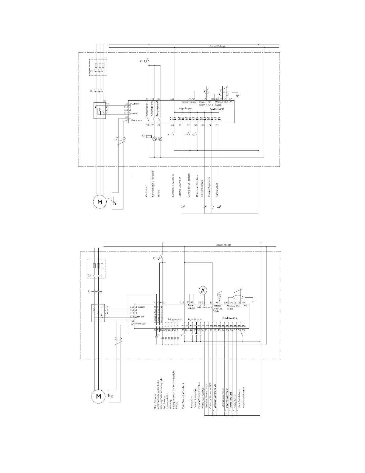
Figure 1-1 shows an example of a single-line system for EntelliPro ES3 and ES5.
1.4 EP
MOTOR MANAGEMENT SYSTEM – INSTRUCTION MANUAL
Page 13
CHAPTER 1: INTR ODUCTION
EntelliproES3DOLstandardconfiguration
EntelliPro ES5 DOL standard configuration
Figure 1-1: Single-line diagram
EP OS MOTOR MANAGEMENT SY STEM – INSTRUCTION MANUAL 1.5
Page 14

CHAPTER 1: INTR ODUCTION
1.1.4 EntelliPro ES order code
Five unique catalog numbers are offered:
EntelliPro ES3 DP 2 0
EntelliPro ES3 DP 3 0
EntelliPro ES5 DP 2 2
EntelliPro ES5 DP 2 3
EntelliPro ES5 DP 3 3
The EntelliPro ES catalog configuration definition is shown below:
EntelliPro ES3 – basic functionally
EntelliPro ES5 – advanced
2 = Additional 9x external inputs rated
24Vdc
8
3 = Additional 9x external inputs rated
110
8
DP = Profibus DP / Modbus
2 = Power supply and 7x Digital Inputs rated
24Vdc.
3 = Power supply and 7x Digital Inputs rated
110/240Vac
0 = No external inputs available.
3
ouput
available.
available.
outputs
available.
- 240
Vac
outputs
available.
available
EntelliPro ES3 DP 2
f
unctionally
RTU
2
1.6 EP OS MOTOR MANAGEMENT SYSTEM – INSTRUCTION MANUAL
Page 15

CHAPTER 1: INTR ODUCTION
Table 1-1 shows features and protections available for the five catalogs.
Features / Protections
24Vdc
Supply
110/240Vac
24Vdc (7) Digital Input X X
24Vdc (16) Digital Input X
110/240Vac (7) Digital Input X
110/240Vac (9) Digital Input X
110/240Vac (16) Digital Input X
5A 240Vac/2.5A 24Vdc
Output Contact
2A 240Vac/2A 24Vdc
Output Contact
LT (Thermal Overload) X X X X X
Ground Fault X X X X X
Phase Loss X X X X X
Current Unbalance X X X X X
Thermistor function X X X X X
Stalled Rotor X X X X X
Under Current X X X X X
4-20mA Output X X X
Metering X X X X X
Unit
Communication LED X X X X X
Time stamped event logging X X X X X
Time stamped analog value logging X X X X X
11 Pre Programmed Motor Starter Logic X X X X X
Programmable thresholds X X X X X
Operating hours/Swit ch Counter register X X X X X
Communication (Modbus and Profibus) X X X X X
input X X X
Supply
input X X
(qty.
3)
(qty.
5)
Healthy
Indication LED X X X X X
Table 1-1: List of features and protections
EntelliPro
ES3 DP 2 0
X X X X X
EntelliPro
ES3 DP 3 0
EntelliPro
ES5 DP 2 2
X X X
EntelliPro
ES5 DP 2 3
EntelliPro
ES5 DP 3 3
EP OS MOTOR MANAGEMENT SY STEM – INSTRUCTION MANUAL
1.7
Page 16

CHAPTER 1: INTR ODUCTION
1.1.5 EntelliPro ES Current Transformer Definition
There are three items that must be considered when configuring the motor load level of the EntelliPro ES. The items to
consider are the transformer type, the number of primary windings, and the EntelliPro ES full load current setting (FLA).
Four unique current transformer catalog numbers are offered:
EntelliPro CT 8
EntelliPro CT 32
EntelliPro CT 64
EntelliPro CT 630
The CT catalog configuration definition is shown below:
Current Transformer Designator
Nominal CT Currente
(refer to section 1.2.3 for
current ranges and
Use of the appropriate transformer will allow the FLA setting to be configured in the range of CT/6 to CT. For example , if the
EntelliPro CT 64 transformer is chosen, the FLA setting can be configured from 64/6=10.7 amps to 64 amps in 0.1 amp
increments.
There may be cases where the available transformer types have inappropriate ranges for the application. For example,
when trying to protect the motor load level at 77 amps, the EntelliPro CT 64 is too small. Considering the EntelliPro CT 630
would result in the lowest FLA setting of 630/6=105 amps, which is too large for this application.
This case would require using multiple turns on the CT primary (see figure 1-2 and equation below). The solution to the
77 amp example is to use an EntelliPro CT 630 with two primary turns. The nominal CT current = 630 / 2 = 315 amps. This
would set the FLA range from 52.5 amps (315/6) to 315 amps. So, 77 amps could be selected.
Use of the minimum number of primary turns is recommended.
In addition, these CTs can be used as interposing CTs to increase the primary current.
accuracy).
EntelliPro
CT
8
Nominal CT Current
# of loops
as 2A CT
Nominal Current (CT with loops)
Example using EntelliPro CT 8
Calculating # of primary loops required
# of primary loops = 8/2 = 4 Turns
=
Figure 1-2: Primary feeding loops
1.8 EP OS MOTOR MANAGEMENT SYSTEM – INSTRUCTION MANUAL
Page 17

CHAPTER 1: INTR ODUCTION
1.2 Specifications
NOTE: Specifications are subject to change without notice.
1.2.1 Protection Specifications
Overload Fault (Thermal Model)
IEC Class curves ....................................................................5, 10, 15, 20, 25, 30, 35, 40 (IEC 60947)
Thermal overload pickup ..................................................1.20
Motor full-load current (FLA) ............................................1/6 Ict to Ict in steps of 0.1
Curve biasing
Phase loss: ....................................................................1.83 x Ir
Phase unbalance: .......................................................1.43 x Ir
Timing accuracy....................................................................±10% up to 8 x FLA and ±20% from 8 to 10 x FLA
Elements ................................................. ..................................fault (trip) and warning (alarm) - warning not valid for ATEX
Phase Loss
Range ........................................................................................fixed at 60% (any phase <40% of max phase)
Accuracy...................................................................................±5%
Time delay................................................................................0–15 seconds in steps of 1s (0 = disable)
Timing accuracy.................................................................... ±20%
Elements ................................................................................... fault (trip) and warning (alarm) - warning not valid for ATEX
Current Unbalance
Range.........................................................................................fixed at 30% (any phase <70% of max phase)
Accuracy...................................................................................±5%
Time delay................................................................................0–15 seconds in steps of 1s (0 = disable)
Timing accuracy....................................................................±20%
Elements ................................................. ..................................fault (trip) and warning (alarm)
immediately
Fix to 500ms when ATEX is selected
when ATEX is selected
Ground Fault
Pickup level..............................................................................20–100% of FLA in steps of 10%
Trip time delay band ...........................................................0.1–1.0s in steps of 0.1s (other values will generate an error)
Timing accuracy....................................................................±20%
Elements ................................................. ..................................fault (trip) and warning (alarm)
EP OS MOTOR MANAGEMENT SY STEM – INSTRUCTION MANUAL 1.9
Page 18

CHAPTER 1: INTR ODUCTION
Thermistor
types:
Sensor
..........................................................................PTC (RHOT = 3.6 kΩ, RRESET = 1.5 kΩ)
Time delay................................................................................500ms
Elements ................................................. ..................................fault (trip) and warning (alarm) - warning not valid for ATEX
Connection ..............................................................................1, 3 or 6 thermistors in series
S
tandard
Max cable length to detect short ..................................AWG 14 = 266m AWG 16 = 160m AWG 20 = 70m
........................................................ .........................IEC 34-11-12
1.2.2 Metering and monitoring specifications
Event Recorder
Capacity....................................................................................250 events
Data storage...........................................................................non-volatile memory
Phase Metering
Accuracy...................................................................................±5% with external CT
Elements ...................................................................................single phase, average
1.2.3 Input specification
Digital Inputs
Fixed pickup ............................................................................16.8Vdc (24Vdc version)
77Vac (110/240Vac version)
Fixed drop-off .........................................................................10Vdc (24Vdc version)
30Vac (110/240Vac version)
UTION: The usage of voltage between the drop-off and pickup range is not recommended.
CA
Recognition time ...................................................................40 msec
Current draw at rated voltage ........................................5ma on 24Vdc (24Vdc version)
7ma on 240Vac (120/240Vac version)
Type
............................................................................................opto-isolated inputs
Maximum input voltage.....................................................28.8Vdc (24Vdc version)
275Vac (120/240Vac version)
1.10 EP OS MOTOR MANAGEMENT SYSTEM – INSTRUCTION MANUAL
Page 19
Phase Current Inputs
Range...............................................................................................8A CT: 1.34–8.0A (10 x CT)
32A CT: 5.30–32A (10 x CT)
64A CT: 10.6–64A (10 x CT)
630A CT: 105–630A (10 x CT)
CHAPTER 1: INTR ODUCTION
Frequency
Accuracy...................................................................................with external CT: ±5% / direct: ±2%
.................................................................................47.5 to 63.0 Hz
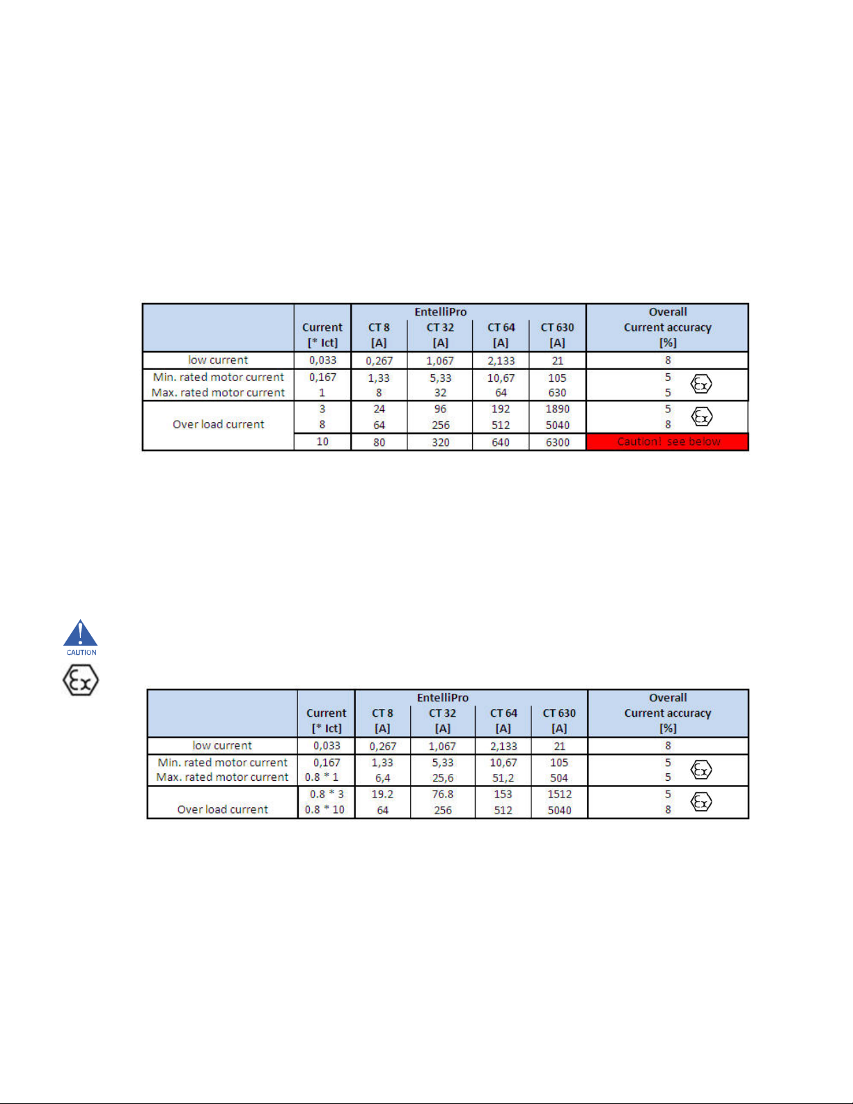
Table 1-2: EntelliPro ES CT types primary current ranges and accuracy
Table below shows the nominal motor current range that the EntelliPro CTs can be used.
The range can be enlarged by feeding multiple primary loops. refer to section 1.1.5.
CAUTION: The overcurrent range above 8*Ict cannot be used to protect motors in explosive areas, due to decrease
accuracy. If motor protection up to 10 *Ict is desired , the nominal current must be derated per the table below.
Example
Motor rated current X is 32 A and motor inrush current is 7X, that is 224 A. EntelliPro CT 32 can be used in ATEX area.
Motor rated current X is 25 A and motor inrush current is 9X, that is 225 A. EntelliPro CT 32 can be used in ATEX area.
Motor rated current X is 32 A and motor inrush current is 9X, that is 288 A. EntelliPro CT 32 must not be used in ATEX area.
Use EntelliPro CT 64 in ATEX area.
EP OS MOTOR MANAGEMENT SY STEM – INSTRUCTION MANUAL 1.11
Page 20

CHAPTER 1: INTR ODUCTION
1.2.4 Output specifications
4 - 20 mA Output
Accuracy...................................................................................±1% from displayed RMS
Motor Contact Relays
Configuration..........................................................................electromechanical SPST
Contact material ...................................................................silver alloy
Operate time...........................................................................10ms
Minimum contact
load
.......................................................10mA at 5Vdc
Continuous current ..............................................................5A at 240Vac / 30Vdc
Resistive load capacity
Maximum switched power ...............................................150W or 1250VA
Maximum switched current .............................................5A
Maximum switched voltage.............................................150Vdc or 250Vac
Life expectancy
Mechanical ............................................ ..................................20 million operations
Electrical ..................................................................................100,000 operations at 5A, 30Vdc or 250Vac
Application category (for AC-15 and DC-13) ............5A/240VA – AC-15
2.5A / 24Vdc – DC-13
According to IEC-60947-5-1 Normal and Abnormal Conditions
A7DQS or gl 10Amps fuses required
Signal Relays
Configuration..........................................................................electromechanical SPST
Contact material ...................................................................silver alloy
Operate time...........................................................................10ms
Minimum contact
load
.......................................................10mA at 5Vdc
Continuous current ..............................................................3A at240Vac
Resistive load capacity
Maximum switched current .............................................3A
Maximum switched voltage.............................................150Vdc or 250Vac
Life expectancy
Mechanical ............................................ ..................................20 million operations
Electrical ..................................................................................100,000 operations at 5A, 30Vdc or 250Vac
1.12 EP OS MOTOR MANAGEMENT SYSTEM – INSTRUCTION MANUAL
Page 21

CHAPTER 1: INTR ODUCTION
1.2.5 Power supply specifications
This section lists the specifications for the power supply. The power consumptions of the EntelliPro
modules are listed in Table 1-3.
Nominal.....................................................................................24Vdc (24Vdc version)/140mA (max)
110/240Vac (120/240Vac version)/60mA (max)
Range.........................................................................................19–28.8Vdc (24Vdc version)
77–264Vac (110/240Vac version)
Ride-through...........................................................................30ms
1.2.6 Communication specifications
Profibus
Port..............................................................................................opto-isolated
Modes ........................................................................................DP V1 slave, up to 12Mbps
Connector ................................................................................9-pin D connector
S
tandard
...................................................................................IEC 61158
Installation .................................................. .............................PI installation guidelines
Modbus RTU over RS485
Port...............................................................................................opto-isolated
Baud rates ...............................................................................up to 19.2kbps (Modbus
Protocol .....................................................................................half-duplex
EP OS MOTOR MANAGEMENT SY STEM – INSTRUCTION MANUAL
1.13
Page 22

Pper
CHAPTER 1: INTR ODUCTION
1.2.7 Testing and certification
Test Reference Standard Test Level
Dielectric voltage
withstands
..........................................1.5kV
Impulse voltage
withstand
..............................................EN60255-5
Electrostatic discharge.......................................................EN61000-4-2/IEC60255-22-2 Level 4
RF
immunity
Fast transient
Surge
Conducted RF
............................................................................EN61000-4-3/IEC60255-22-3 Level 3
immunity
disturbance
................. ..................................................EN61000-4-5/IEC60255-22-5 Level 3
immunity
...............................................EN61000-4-4/IEC60255-22-4 Class A
....................................................EN61000-4-6/IEC60255-22-6 Level 3
Radiated and conducted emissions.............................CISPR11 /CISPR22/ IEC60255-25 Class A
Sinusoidal vibration ...........................................................IEC60255-21-1 Class 1
Voltage dip and interruption ..........................................IEC61000-4-11 0, 40, 70% dips, 250/300 cycle interrupts
Harmonics ..............................................................................IEC61000-4-13
Voltage ripple ........................................................................IEC61000-4-17 15% ripple
Environmental (cold)................................................. .........IEC60068-2-1 -25° C, 96 hrs
Environmental (dry heat) .................................................IEC60068- 2-2 70° C, 96 hrs
Relative humidity
cyclic
...................................................IEC60068- 2-30 6-day variant 2
Short-circuit current*.........................................................IEC60947-5-1
Pollution degree...................................................................I
Rated impulse withstand voltage ............................4kV
Overvoltage category II according to IEC 60947-1 7.2.3.1 item 2) b)
(when EntelliPro ES is directly connected to the main voltage)
Overvoltage category III according to IEC 60947-1 7.2.3.1 item 2) b)
(when EntelliPro ES is not directly connected to the main voltage)
ATEX certificatio
SIL1
Profibus certification
*CAUTION: A maximum A7DQS or gl 10A fuse is required on motor relays.
1.14 EP OS MOTOR MANAGEMENT SYSTEM – INSTRUCTION MANUAL
Page 23

CHAPTER 1: INTR ODUCTION
1.2.8 Approvals
Applicable Council Directive According to Low-Voltage Directive EN60255-5, EN61010-1
CE compliance: EMC Directive EN50263 / EN61000-6-2/ EN61000-6-4
ISO: Manufactured under a registered quality program – ISO9001
ROSH compliance:
1.2.9 Physical specifications
The size and weight of the EntelliPro ES module is as follows:
Size ..............................................................................................135mm (W) x 82.5mm (H) x104.5mm (D)
Weight ………………………………….................................................0.45kg
1.2.10 Environmental specifications
Ambient temperatures .......................................................storage/shipping: –40° to 90° C
Humidity
...................................................................................operating up to 95% (non-condensing) at 55° C (per IEC60068
operating: –20° to 60° C
2- 30 Variant 2, 6
days)
operating up to 95% (non-condensing) at 55° C (per IEC60068-
2- 30 Variant 2, 6 days)
Altitude
......................................................................................2000m (max)
EP OS MOTOR MANAGEMENT SY STEM – INSTRUCTION MANUAL
1.15
Page 24
CHAPTER 1: INTR ODUCTION
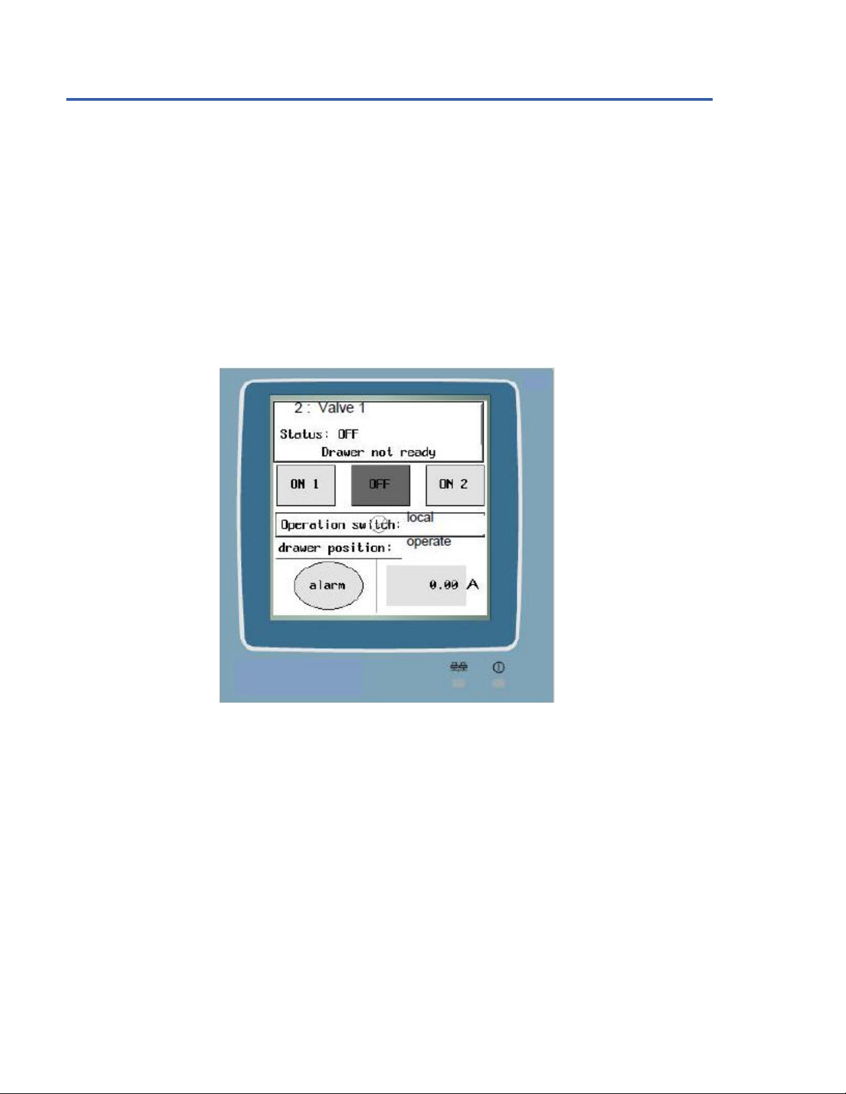
1.3 EntelliPro CP3/CP5 HMI
The EntelliPro CP3 and CP5 HMI, shown in Figure 1-3, is a microprocessor-based device that connects to an
standard
Modbus RTU on RS-485 wiring.
The HMI is factory programmed to communicate with the EntelliPro ES devices in a MCC environment in order to
provide a convenient station for viewing metering, status and setting information and controlling contactors
operations.
EntelliPro CP5 HMI can be connected to multiple EntelliPro ES devices in the MCC network, while the EntelliPro CP3
HMI is mainly connected to a single EntelliPro ES device.
For additional information on the HMI refer to www.beijerelectronics.com.
industry-
Figure 1-3: HMI front screen
1.16 EP OS MOTOR MANAGEMENT SYSTEM – INSTRUCTION MANUAL
Page 25
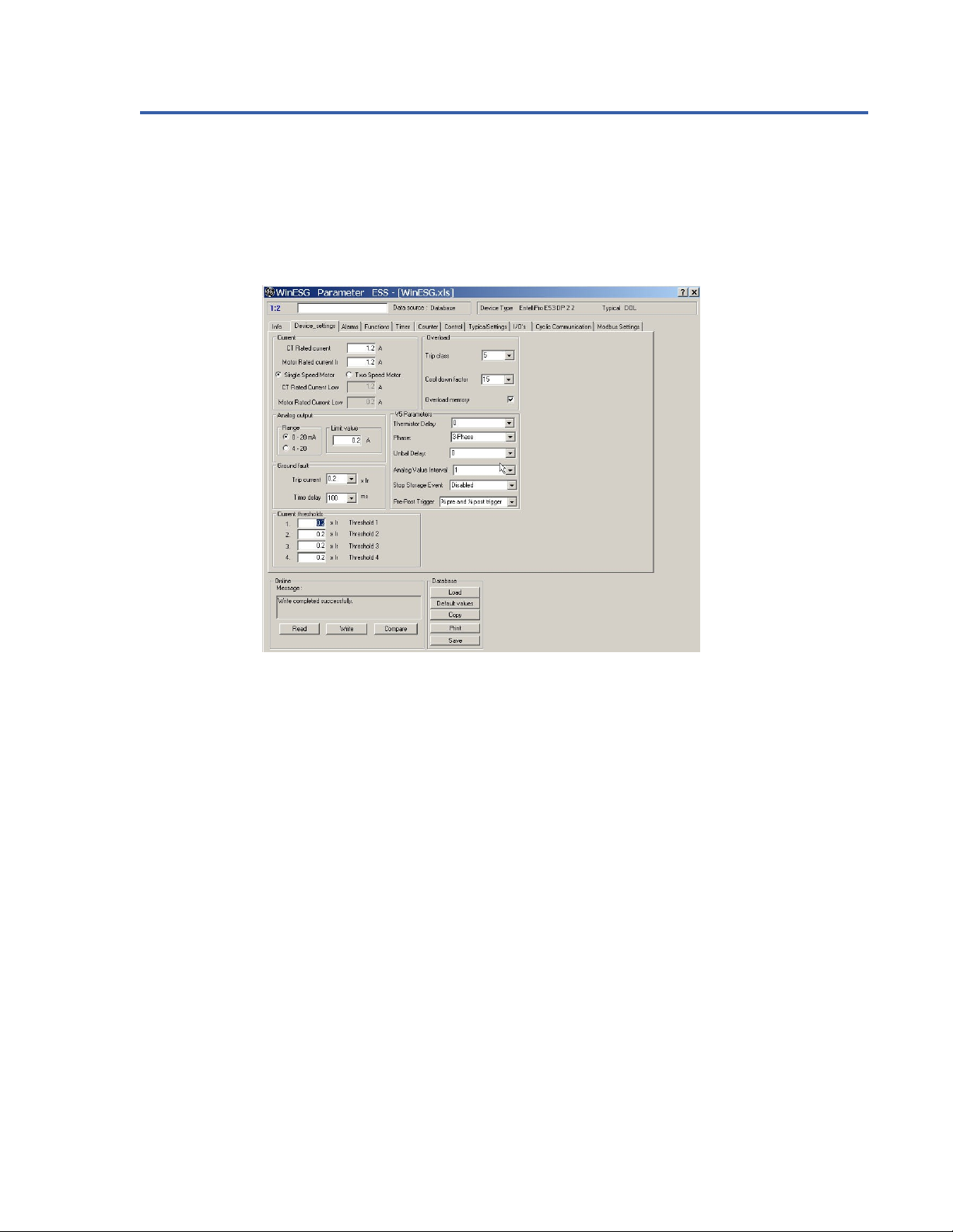
1.4 WinESG Configuration Tool
WinESG is a Profibus-based HMI used with the EPOS System to configure the EntelliPro ES. It provides the capability
for a full parameterization and configuration of the EntelliPro ES devices. In addition it supports metering, event log,
analog data retrieval, and downloading of custom logic application. Refer to Chapter 5 for detailed operation of the
WinESG.
Figure 1-4 shows the parameterization panel view of the WinESG Set-up software.
CHAPTER 1: INTR ODUCTION
Figure 1-4: WinESG Panel
EP OS MOTOR MANAGEMENT SY STEM – INSTRUCTION MANUAL 1.17
Page 26
CHAPTER 2: INSTALL ATION/CONFIGURATION
GE Industrial Solutions
EPOS Motor Management System
Chapter 2: Installation / Configuration
2.1 Installation and initial operating
The EntelliPro ES is an intelligent motor control relay that is mainly installed in low voltage systems for industrial usage.
To ensure safe operation, several measures must be taken.
CAUTION: Only use genuine draw out units produced by the factory. Observe proper cable laying in the cable terminal
compartment and outside the switch cabinet.
CAUTION: Only qualified personnel are allowed to install, commission, maintain or modify this device in accordance
with relevant requirements.
The following tables show the recommended cable type and spacing.
Cable type Category
power cable (400VAC....) A
control cable B
function cable (TMA, ...) C
bus cable D
Table 2-1: Recommended EntelliPro ES Cable listing
Table 2-2: Recommended cable spacing
NOTES:
Do not use multi-stranded cable with combinations from categories A to D.
The PE-connection of the EntelliPro ES must be connected.
The maximum length of the connection cable to the current transformer is 20 cm.
Before initial commissioning of the installation the communication bus wiring and the signal quality must be
tested with a Profibus/Modbus test and diagnostic device.
All wires connected to the EntelliPro ES- modules must be checked prior to operation.
EP OS MOTOR MANAGEMENT SY STEM – INSTRUCTION MANUAL 2.1
Page 27
CHAPTER 2: INSTALL ATION/CONFIGURATION
2.1.1 Mechanical installation
This section describes the mechanical installation of the EPOS system, including dimensions for mounting and
information on module withdrawal and insertion.
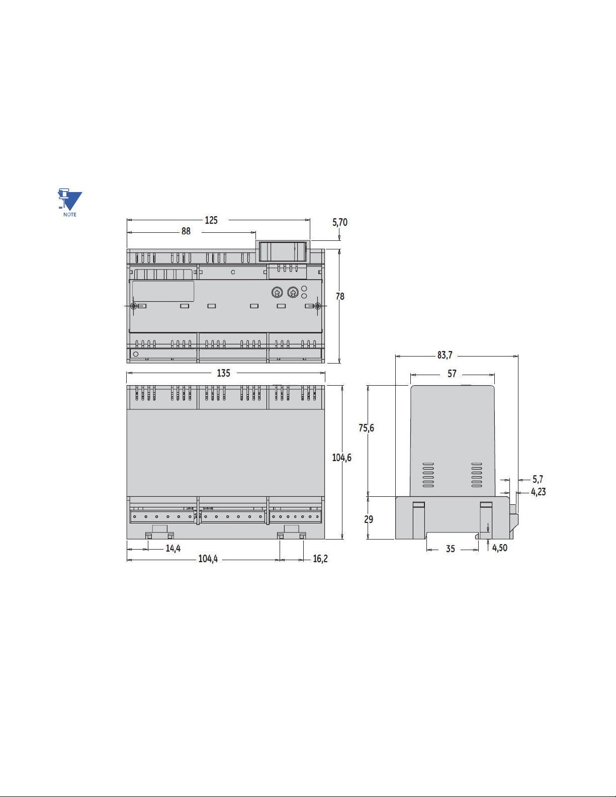
2.1.1.1 Dimensions
The EntelliPro ES is packaged in a modular arrangement . Figure 2-1 shows the dimensions of the EntelliPro ES.
NOTE: All dimensions are in mm.
Figure 2-1: EntelliPro ES Dimension
EP OS MOTOR MANAGEMENT SYSTEM – INSTRUCTION MANUAL
2.2
Page 28
OS
CHAPTER 2: INSTALL ATION/CONFIGURATION
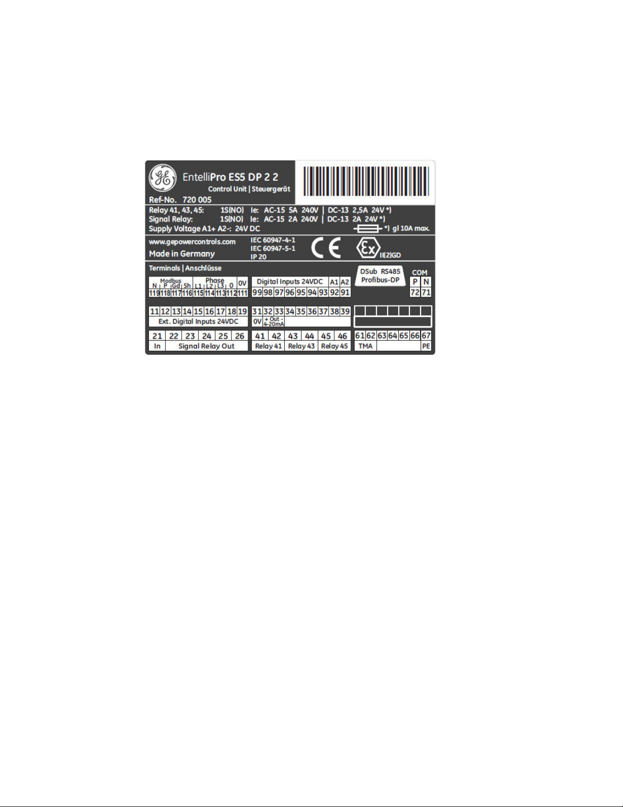
2.1.1.2 Product identification
The product identification label is located on top of the EntelliPro ES module. This label indicates the product catalog
number (EntelliPro ES5 2 2), reference number, terminal numbers, relay rating, power supply rating, and agency
certification among other parameters. The fiigure below shows an example of the label.
Figure 2-2: EntelliPro ES label example
2.1.1.2.1 Label Definition
The following description is applicable to the label in figure 2-2.
EntelliPro ES5 DP 2 2 defines the catalog number of the device.
Ref-No. is a GE defined number for the unit .
Relays 41, 43, and 45 are motor relays rated AC-15 5A/240Vac and DC-13
2.5A/24Vdc Supply Voltage A1+ A2-: 24V DC, indicates that the power supply for this
unit is 24Vdc. Terminal definitions:
N Modbus – connection
P Mobdbus + connection
Gd Modbus common connection
Sh Shield connection
L1 Phase L1 connection
L2 Phase L2 connection
L3 Phase L3 connection
Phases L1/L2/L3 common connection
0V(111) Digital inputs (93…99) common
0V(31) External Digital inputs (11…19) common
DSub RS485 Profibus indicates the Profibus DP connection
EP
2.3
MOTOR MANAGEMENT SY STEM – INSTRUCTION MANUAL
Page 29
CHAPTER 2: INSTALL ATION/CONFIGURATION
2.1.1.3 Mounting
CAUTION: To avoid the potential for personal injury from fire hazards, ensure the unit is mounted in a safe
location and/or within an appropriate enclosure. Unit must be un-powered and all connectors removed
during installation.
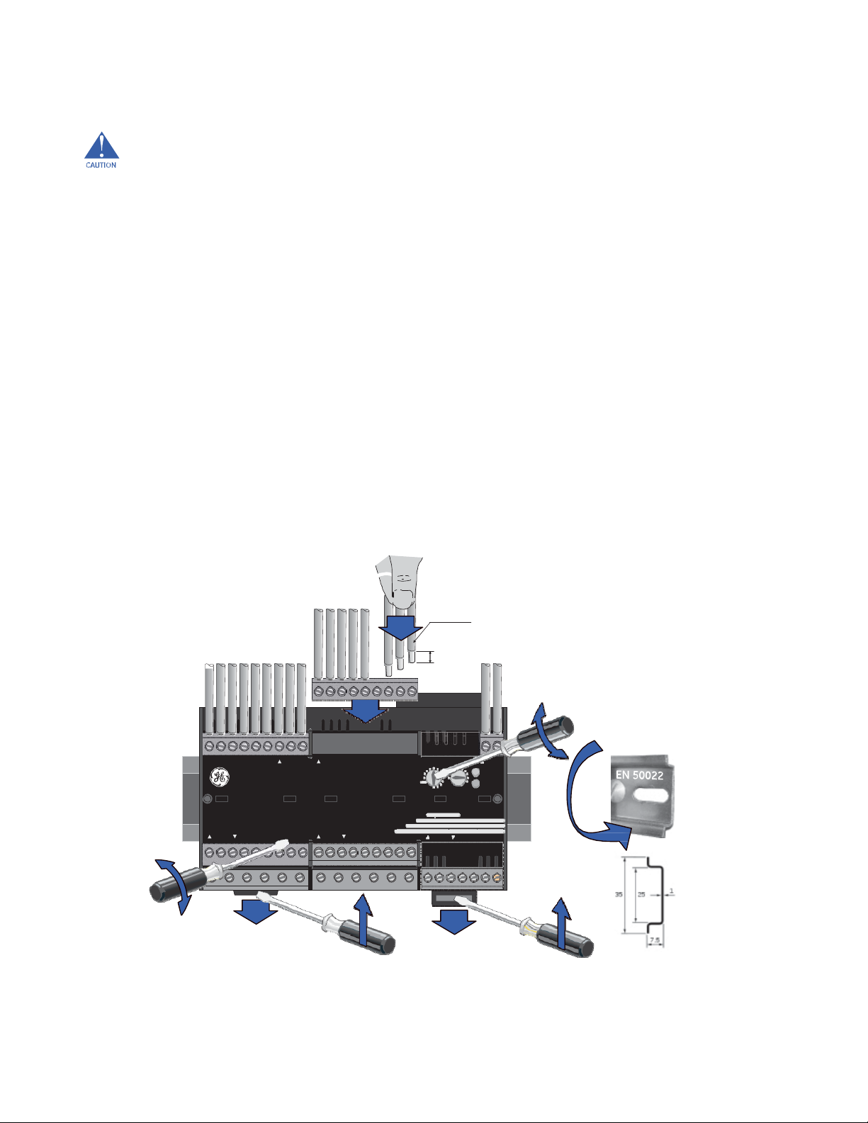
The EntelliPro ES can be DIN mounted using DIN rail to the equipment . The DIN rail mounting, removal, wire
connection and connector insertion and removal are illustrated in Figure 2-3.
Steps for installation and removal:
A. Secure DIN Rail (see Item A) to the panel with an appropriate fastener.
B. To insert the unit , snap the EntelliPro ES to the Din rail while releasing the pressure on the unit
mounting tabs (see Item B). To remove lift the unit out while holding the tabs up with a
screwdriver or another appropriate tool.
C. To insert the connector simply push the connecter toward the EntelliPro terminal (see Item
C). Ensure you have the appropriate connector. To remove, separate the connector from the
housing using the tip of a small screwdriver (see Item C) or other appropriate tool.
D. Insert each wire into the connector (see Item D) and tighten the connection using the torque
shown in the figure. Lightly pull on the wire to check the connection.
E. Use a small screwdriver or other appropriate tool to adjust the Modbus and Profibus
communication address switch (see Item E).
1 x
2,5mm²
AWG...
Address
A
D
9
C
119-111 99-91
EntelliProES
11-19 21-26 31-39 41-46 51-57 61-67
4 4
2 6 2
0 0
D
10
E
72-71
6
COM
8
RUN
50022
EN
12
Address
G = default
C
B
B
Figure 2-3: EntelliPro ES DIN rail mounting and removal
EP OS MOTOR MANAGEMENT SYSTEM – INSTRUCTION MANUAL
2.4
Page 30

OS
CHAPTER 2: INSTALL ATION/CONFIGURATION
2.1.1.4 EntelliPro ES Connector terminal identification
The EntelliPro ES connectors pinout and description are shown in Table 2-3
Connector Number Description
11 Digital Input ( 24Vdc + or 110/230vac)
12 Digital Input ( 24Vdc + or 110/230vac)
13 Digital Input ( 24Vdc + or 110/230vac)
14 Digital Input ( 24Vdc + or 110/230vac)
15 Digital Input ( 24Vdc + or 110/230vac)
16 Digital Input ( 24Vdc + or 110/230vac)
17 Digital Input ( 24Vdc + or 110/230vac)
18 Digital Input ( 24Vdc + or 110/230vac)
19 Digital Input ( 24Vdc + or 110/230vac)
Table 2-3: Connector number and description
21 Common for
22 Signal
23 Signal
24 Signal
25 Signal
26 Signal
31 Digital Inputs Common for Inputs 11 to 19
32 4– 20 mA Output (+)
33 4-20 mA Output ( -)
41 Digital Motor
42 Digital Motor
43 Digital Motor
44 Digital Motor
45 Digital Motor
46 Digital Motor
61 PTC Temperature Sensor
62 PTC Temperature Sensor
67 Ground (PE)
91
92
93 Digital Input (24Vdc+ or 110/230Vac)
94 Digital Input (24Vdc + or 110/230vac)
95 Digital Input (24Vdc + or 110/230vac)
96 Digital Input (24Vdc + or 110/230vac)
97 Digital Input (24Vdc + or 110/230vac)
98 Digital Input (24Vdc + or 110/230vac)
99 Digital Input (24Vdc + or 110/230vac)
111 Digital Inputs Common for Inputs 93 to 99
112 CT output , Common
113 CT output , Phase L3
114 CT output , Phase L2
115 CT output , Phase L1
116 Shield
117 Communication Common
118 Modbus D-Positive
119 Modbus D-Negative
Supply
Supply
Relay
Outpus 22 to 26
Relay 22
Output
Relay 23
Output
Relay 24
Output
Relay 25
Output
Relay 26
Output
Relay
Output 41
Relay
Output 41 RTN
Relay
Output 43
Relay
Output 43 RTN
Relay
Output 45
Relay
Output 45 RTN
Voltage (24Vdc - or 110/230Vac)
Voltage (24Vdc + or 110/230Vac)
EP
2.5
MOTOR MANAGEMENT SY STEM – INSTRUCTION MANUAL
Page 31

CHAPTER 2: INSTALL ATION/CONFIGURATION
2.1.2 Electrical installation
This section describes the electrical installation of the EntelliPro ES motor relay.
CAUTION: EntelliPro ES is not to be used in any way other than described in this manual.
2.1.2.1 Power supply connection
EntelliPro ES3 DP 2 0 and EntelliPro ES5 DP 2 2 are 24Vdc supply input versions, while EntelliPro ES3 DP 3 0,
EntelliPro ES5 DP 3 2, and EntelliPro ES5 DP 3 3 are 110 to 240Vac versions.
The operation range for the 24Vdc units is 19Vdc to 29Vdc. The operation range for the 110 to 240Vac units is
77Vac to 266Vac.
CAUTION: Check the voltage rating of the unit before applying control power. Control power outside of the operating
range of the power supply will damage the EntelliPro ES.
Figure 2-4 shows the EntelliPro wiring connections. Refer to Item A for power supply connections.
Figure2‐4:EntelliProESwiringconnections
EP OS MOTOR MANAGEMENT SYSTEM – INSTRUCTION MANUAL
2.6
Page 32

CHAPTER 2: INSTALL ATION/CONFIGURATION
phase current input connections.
2.1.2.2 Communication connection
Two two-wire RS485 ports (Modbus RTU and Profibus) are available. Up to 32 EntelliPro ES relays can be daisy- chained
together on a communication channel without exceeding the driver capability. Commercially available repeaters can
be used to add more than 32 relays. A suitable cable should have the characteristic impedance of
120 ohms (for example, Belden #9841) and total wire length should not exceed 1200 meters (4000 ft .). Commercially
available repeaters will allow for transmission distances greater than 1200 meters.
Voltage differences between remote ends of the communication link are not uncommon.
For this reason, surge protection devices are internally installed across all RS485 terminals. Internally, an isolated
power supply with an optocoupled data interface is used to prevent noise coupling.
CAUTION: To ensure that all devices in a daisy-chain are at the same potential, it is imperative that the common
terminals of each RS485 port are tied together and grounded only once at the master or at the EntelliPro ES. Failure to
do so may result in intermittent or failed communications.
Refer to Figure 2-4, Item B for Modbus communication connections. Profibus connections are made on
disconnect
. F or
information on Profibus cable types and lengths, refer to the installation guide for Profibus wiring on the PI
Center home page http://www.Profibus.com/nc/downloads.
2.1.2.3 Thermistor connection
A positive temperature coefficient (PTC) thermistor can be directly connected to the EntelliPro ES TMA terminals. Refer
to Figure 2-4, Item C, for thermistor connection. Connection must be in accordance to IEC 34-11-2.
2.1.2.4 Phase Current Connection
The EntelliPro ES has three channels for phase current inputs. The phase CTs should be chosen so the FLA is not less
than 1/6 of the rated phase CT primary. Ideally, the phase CT primary should be chosen such that the FLA
is 100% of the phase CT primary or slightly less, never more. This will ensure maximum accuracy for the current
measurements. The maximum phase CT primary current is 6400A, with additional interposing CT.
CAUTION: Polarity of the phase CTs is critical for the ground fault calculation. Refer to Figure 2-4, Item D for typical
2.1.2.5 Input/output connection
EntelliPro ES has 16 inputs, 3 form A motor output relays and 5 form A signal output relays.
NOTE: The number of Inputs and outputs depends on the catalog number.
Inputs can be mapped to any of the input functions, such as contactor 1 On command, contactor 2 On command,
contactor feedback, etc. Inputs can also be configured as active high or low signals. In an input is configured as active
low, the input will be active if the voltage is below the fixed drop-off threshold. If an input is configured as active high,
the input will be active if the voltage is above the fixed pick-up threshold. Refer to section 1.2.3 for input electrical
specification. The complete list of input mapping is shown in Table 2-4.
Refer to Figure 2-4, Items E (outputs) and F (inputs), for typical output and input connections.
EP OS MOTOR MANAGEMENT SY STEM – INSTRUCTION MANUAL 2.7
Page 33

CHAPTER 2: INSTALL ATION/CONFIGURATION
Digital Input Mapping
Active High Signal Active Low Signal
ON1 Command ON1 Command
ON2 Command ON2 Command
OFF Command OFF Command
Main Contactor 1 Feedback
MCCB ON Feedback
Main Contactor 2 Feedback
MCCB OFF Feedback
Start Contactor Feedback Signal
Breaker Charged Status Signal
Bypass
Feedback
Limit Switch 2 Limit Switch 2
Limit Switch Close Limit Switch Close
Feedback 4 Feedback 4
Delta Contactor Feedback Signal
Soft Starter Up to Speed feedback
Torque Swit ch1
Torque Ope n Torque Ope n
Breaker tripped2 Breaker Tripped2
External Fault Signal 1 (External Supervision) External Fault Signal 1 (External Supervision)
External Supervision Feedback External Super vision Feedback
Breaker
ready
for Switch On Breaker
Torque Clo se Torque Cl ose
Torque Swit ch 2 Torque Switch 2
Drawer Test Position Signal Drawer Test Position Signal
Drawer Operation Position Signal Drawer Operation Position Signal
Remote Input Signal Remote Input Signal
Local Input Signal Local Input Signal
Reset Alarms Input Signal Reset Alarms Input Signal
Main Circuit Feedback Main Circuit Feedback
Control Circuit Feedback Control Circuit Feedback
Emergency
Stop Signal
Safety Circuitry
Limit Switch 1 Limit Switch 1
Limit Switch Open Limit Switch Open
Soft Starter External Fault Soft Starter External Fault
Breaker Tripped 1 Breaker Tripped 1
External Fault Signal 2 (External Supervision) External Fault Signal 2 (External Supervision)
Signal
Main Contactor 1 Feedback
MCCB ON Feedback
Main Contactor 2 Feedback
MCCB OFF Feedback
Start Contactor Feedback Signal
Breaker Charged Status Signal
Bypass
Feedback
Delta Contactor Feedback Signal
Soft Starter Up to Speed feedback
Torque Swit ch1
Ready
for Switch On
Emergency
Stop Signal
Safety Circuitry
Signal
Table 2-4: Input mapping
EP OS MOTOR MANAGEMENT SYSTEM – INSTRUCTION MANUAL
2.8
Page 34

OS
CHAPTER 2: INSTALL ATION/CONFIGURATION
2.1.2.6 4-20mA output connection
Refer to Figure 2-4, Item G, for typical 4-20mA connections.
2.1.2.7 Dielectric strength testing
It may be required to test a complete motor starter for dielectric strength (“flash” or “HIPOT”) with the EntelliPro ES
Installed. The EntelliPro ES is rated for 1.5 kV AC for 1 second isolation between relay contacts, EntelliPro ES
CT inputs and the PE terminal (66). Some precautions are required to prevent damage to the EntelliPro ES during
these tests.
To avoid damage to filter capacitors and transient suppressors by continuous high voltage, disconnect the PE
terminal during testing of power supply inputs. The CT inputs, inputs, and output relays do not require any special
precautions. Low voltage inputs (less than 30 volts), and RS485 communication ports are not to be tested for
dielectric strength under any circumstance.
EP
2.9
MOTOR MANAGEMENT SY STEM – INSTRUCTION MANUAL
Page 35

Profibus Class 1 master module.
CHAPTER 2: INSTALL ATION/CONFIGURATION
2.2 Motor Control Configuration
This section is split into two parts; one for an expert integrator requiring a full knowledge of all
parameters and configuration and the other requiring minimal knowledge to configure the EntelliPro ES.
For the expert user, refer to section 2.2.1. For non-expert user, refer to sections 2.2.2.
2.2.1 Motor Control Detailed Configuration
The EntelliPro ES can control the motor (start, stop, reset …) by four means: Profibus class 1, which can be
PLC or other automation systems, Modbus RTU master, which can be the EntelliPro CP or other Modbus
RTU base system, Hardwire and WinESG.
The first step in the configuration is to assign the four sources (Profibus class1, CP/Modbus RTU, Hardwire,
WinESG) as locals or remote. This is done in WinESG parameterization/control panel shown in the illustration
below or Modbus function code 6 register 115. If a source is not assigned as remote, it automatically becomes
a local source if enabled by checking the box to the right of the source. Only one remote source can be
selected.
NOTE: If Profibus Class 1 is enabled, the remote source selection can only be set to Class 1.
In addition EntelliPro ES provides a “local-remote-off” switch which selects if locals or remote sources control
the motor ON/OFF operation.
NOTE: Only one source can control the switch.
The following sources can be configured as the controller of the “local-remote-off ” switch configuration:
Profibus Class 1
CP / Modbus RTU The “local-remote-off” switch can only be configured
The “local-remote-off ” switch can only be configured over
over Entellipro CP / Modbus RTU module or other
Modbus masters modules.
Hardwire The “local-remote-off” switch can only be configured with
hardwired input. Switch must be connected to the input
and the input mapped accordingly.
2.10 EP OS MOTOR MANAGEMENT SYSTEM – INSTRUCTION MANUAL
Page 36

CHAPTER 2: INSTALL ATION/CONFIGURATION
Fixed Local Control commands (start, stop, reset etc) can only be issued
by local sources. See section 2.2.1.1 for the local source
listing.
NOTE: If the hardwire connection is set to 1-bit (level)
then locals CP / Modbus RTU and WinESG are disabled. If
hardwire connection is set to 2-bit (edge) input
configuration, the locals CP
/ Modbus RTU and WinESG controls are enabled. See
section 2.2.1.2 for detail of 1-bit and 2-bit configurations.
Fixed Remote Control commands (start, stop, reset etc) can only be issued
by the remote source. See section 2.2.1.1 for the
remote source listing.
The control of the “local-remote-off” switch can be set in WinESG parameterization/control panel or by configuring
Modbus RTU register 115. The switch control in WinESG is shown below:
2.2.1.1 Local and Remote Sources Listing
Local sources are defined as hardwire, CP / Modbus RTU or other Modbus RTU modules, and WinESG.
Remote control sources are defined as hardwire, Modbus RTU or other Modbus RTU modules, and Profibus Class 1,
which can be PLC or other Profibus based automation system.
2.2.1.2 Input Configuration
Input can be configured as 1-bit or 2-bit . If set to 1-bit then a single input is used to control the contactor closing
and opening. If set to 2-bit, one input will be mapped to close the contactor and a different input use to open the
contactor.
The same is applicable to Profibus communication. If set to 1-bit , a single ON1 (or ON2) bit is use to turn the
contactor on and off. If using 2-bit, ON1 (or ON2) bit is used to turn on the contactor and OFF bit is use to open the
contactor.
2.2.1.3 Motor Control via Modbus Configuration
Table 2-5 shows the Modbus register mapping of remote source and switch control selections. By setting register 115
to 34 decimal (0x22), it indicates that Modbus is the remote source and also controls the local-remote-off switch.
EP OS MOTOR MANAGEMENT SY STEM – INSTRUCTION MANUAL 2.11
Page 37

CHAPTER 2: INSTALL ATION/CONFIGURATION
Register Description Bit Definition
115 Bit0 thru Bit2 defines the Remote source
Bit0 – Bit 2
Bit4 thru Bit6 defines the source that co ntrols the local/
remote/ of f switch
Bit 0- bit 2
0 - None
1 - Profibus Class 1
2- Modbus
3-Hardwire
0- None
1- Profibus Class 1
2-Modbus
3-Hardwaire
4-Fixed Local
5-Fixed Remote
Table 2-5 Remote source and switch control selection via Modbus
To start contactor1, Modbus command function code 5 register 11 set to ON selects the remote source
(Modbus), as a means to control the start/stop/reset operations. This command may be issued only once
upon power up.
Once the remote selection is made, a start command can be issued using Modbus function code 5 register
1.
To start contactor2, Modbus command function code 5 register 11 set to ON selects the remote source
(Modbus), as a means to control the start/stop/reset operations.. Once the remote selection is made a start
command can be issued using Modbus function code 5 register 2.
To start the contactors, Modbus command function code 5 register 10 set to ON selects the local sources
(hardwire, Modbus RTU and WinESG), as a means to control the start/stop/reset operations. This command
may be issued only once upon power up.
Once the local selection is made, a start command can be issued from any local sources.
EP OS MOTOR MANAGEMENT SYSTEM – INSTRUCTION MANUAL
2.12
Page 38

CHAPTER 2: INSTALL ATION/CONFIGURATION
2.2.1.4 Motor Control via WinESG
Similar configuration as above can be done using GE configuration software WinESG. Refer to WinESG
parameterization /control panel on Chapter 5.
2.2.1.5 Motor Control via Profibus Class 1
After configuring the switch control via Modbus or WinESG, write telegram B10008 can be
contactors. Refer to Chapter 4 for additional information on
this telegram.
2.2.1.6 ATEX Configuration
EntelliPro ES can be configured for use in potentially explosive atmospheres (ATEX). Configuration of EntelliPro ES as
ATEX can be done using Modbus RTU master or WinESG configurator tool ONLY (Profibus-DP Class1 CANNOT be used):
WinESG Configurator - refer to WinESG parameterization typical settings panel in section 5.3.2.8.
Modbus by settings register 111 bit 0 to 1, using Function Code 06.
Certain configuration restrictions are placed when configured as ATEX:
Overload protection cannot be disabled or set as warning. It must be configured as fault only.
Thermistor protection cannot be disabled or set as warning. It must be configured as fault only.
Phase Loss cannot be disabled or set as warning. It must be configured as fault only. The Phase Loss time delay is
automatically set to immediate, instead of selectable from 1 to 15 seconds.
Phase Unbalance time delay is automatically set to 500msec instead of selectable from 1 to 15 seconds.
ATEX redundancy contactor is made available.
Auto-Reset parameter can be set to manual reset, one auto-reset, two auto-reset and three auto-reset only. Always
auto-reset is not allowed.
Thermal memory cannot be disabled
.
used to control the
2.2.2 Motor Control Pre-Programmed Configuration
For ease of configuration, EntelliPro ES provides a set of control mode variances that allow easy control of the motor
by different means: Modbus, Profibus Class1, WinESG and Hardwire.
To enable the pre-programmed control configuration, the default configuration must be enabled in the WinESG
parameterization/information panel. To enable the default configuration via Modbus, holding register 62 bit 0 must
be set.
WinESG parameterization/information panel shown in illustration below, can be used to configure the default
configuration parameter.
Six pre-programmed controls variant are available. Following is the configuration of each variant.
NOTE: Control variants 2 and 5 are not applicable to EntelliPro ES3.
EP OS MOTOR MANAGEMENT SY STEM – INSTRUCTION MANUAL 2.13
Page 39

CHAPTER 2: INSTALL ATION/CONFIGURATION
Control Variant 1 Configuration
Profibus Class1 master is enabled, configured as remote source, and has the control of the “local-
remote-off” switch.
Profibus Class1 bus failure detection is enabled. On Class1 bus failure, switch position is forced to
local position.
Modbus failure has not affected the on switch position.
Refer to Figure 2-5.
Figure 2-5: Control variant 1 configuration
EP OS MOTOR MANAGEMENT SYSTEM – INSTRUCTION MANUAL
2.14
Page 40

OS
CHAPTER 2: INSTALL ATION/CONFIGURATION
Control
Variant 2 Configuration
Profibus Class1 master is enabled, configured as remote source, and hard wire has the control o f t h e “local-
remote-off”
Profibus Class1 bus failure detection is ena bled. Class1 bus failure does not affect switch
switch.
position.
Modbus
failure has not affected the on switch
Refer
to Figure
2-6.
position.
Figure
2.15
2-6:Control
variant 2
configuration
EP
MOTOR MANAGEMENT SY STEM – INSTRUCTION MANUAL
Page 41

CHAPTER 2: INSTALL ATION/CONFIGURATION
Control Variant 3 Configuration
Profibus Class1 master is enabled, configured as remote source, and Modbus has the control of the
“local-remote-off”
Profibus Class1 bus failure detection is enabled. On Class1 bus failure, has no effect on the switch
position. On Modbus failure the switch position is forced to local position.
Refer to Figure 2-7.
switch.
Figure 2-7: Control variant 3 configuration
EP OS MOTOR MANAGEMENT SYSTEM – INSTRUCTION MANUAL
2.16
Page 42

OS
CHAPTER 2: INSTALL ATION/CONFIGURATION
Control Variant 4 Configuration
Profibus Class1 master is disabled. Modbus is configured as remote source and has the control of the “localremote-off”
Profibus Class1 bus failure detection is disabled.
On Modbus` failure the switch position is forced to local position
Refer to figure 2-8
switch.
Figure 2-8: Control variant 4 configuration
EP
2.17
MOTOR MANAGEMENT SY STEM – INSTRUCTION MANUAL
Page 43

CHAPTER 2: INSTALL ATION/CONFIGURATION
Control Variant 5 Configuration
Profibus Class1 master is disabled. Modbus is configured as remote source and hardwire has the control
of the “local-remote-off”
Profibus Class1 bus failure detection is disabled.
Modbus failure has no effect on switch
position. Refer to Figure 2-9.
switch.
Figure 2-9: Control variant 5 configuration
EP OS MOTOR MANAGEMENT SYSTEM – INSTRUCTION MANUAL
2.18
Page 44

CHAPTER 2: INSTALL ATION/CONFIGURATION
Control Variant 6
Profibus Class1 master is enabled. Any local sources (Modbus, WinESG, Hardwire) if enabled, can control the motor
operation (ON/OFF).
Profibus Class1 bus failure detection is disabled.
Configuration
Refer to Figure 2-10.
Figure 2-10: Control variant 6
2.19
configuration
EPOS MOTOR
MANAGEMENT
SYSTEM- INSTRUCTION MANUAL
Page 45

CHAPTER 2: INSTALL ATION/CONFIGURATION
2.3 Motor Starter Configuration
There are eleven pre-programmed starter types (typicals), which can be selected via Modbus RTU or Profibus
communication..
The following are the starter types:
Full-voltage non-reversing
Full-voltage reversing
Star-delta open transition
Star-delta reverse open transition
Soft starter
Reverse soft starter
Breaker Control (see note below)
Dahlander
Pole changer
Solenoid valve
Actuator with limit or torque switch
In additional customers can order customized motor starter arrangement by providing GE with desired logic control for
inputs, outputs and timers.
NOTE:
Customer can change pre-defined configurations of any motor starter if the default configuration is not
selected.
NOTE:
Breaker Control selection is NOT available on EntelliPro ES Revision 1.002. Custom logic can be created to
to simulate the application.
To select the motor starter type via Modbus, holding register 62 bit 8 to 11 should be used. Refer to Chapter 4 for
additional Modbus information. WinESG parameterization/information panel shown in the illustration below can be
used to configured the motor starter type.
WARNING: If
timerexceedsthecontactororbreakerclearingtimetoavoidshortcircuit.
“allowdirectionswitchover”isenabled,makesurethe“motorONdirectionswitchovertime”
2.20 EP OS MOTOR MANAGEMENT SYSTEM – INSTRUCTION MANUAL
Page 46

CHAPTER 2: INSTALL ATION/CONFIGURATION
2.3.1 Motor Starter Type - Full-voltage non-reversing starter
The typical full-voltage non-reversing starter type is a full voltage or across the line non-reversing starter.
Before the motor can be turned ON the “drawer ready switch” must be active. In order to activate the “drawer ready
switch” the following must be done:
All faults and device errors must be cleared using WinESG control panel, Modbus function code 6
registers 65 thru 106 depending on the fault type, Profibus class 1 telegram B2701, or hardwire
(make sure an input is mapped to “reset alarm” in WinESG parameterization / I/O panel). Input
mapping can also be done using Modbus function code 6 registers 194 thru 197.
A valid OFF command must be set on hardwire. Make sure an input is mapped to “command OFF”
in WinESG parameterization/I/O panel or Modbus and it is active.
If the drawer supervision is enabled, as shown below the drawer supervision hardwire input must
be active.
Remote or local selection must be made via the appropriate source. The first step is to select the
source (Profibus class 1, Modbus or Hardwire) that has the control of the local-remote s
witch. This
is done in the WinESG parameterization/control panel shown in illustration below.
If Profibus Class 1 is selected as a controlling mechanism, telegram B10008 bit 9 sets the local control and bit 10 sets
the remote control. If bit 9 is set, all mechanisms defined as locals can control the motor (ON/OFF). If bit 10 is set, the
mechanism defined as remote can control the motor (ON/OFF).
If Modbus is selected as a controlling mechanism, either coil command (function code 05) 10, to select local control or
coil command 11 to select remote control must be issued. If coil command 10 is issued, all mechanisms defined as
locals can control the motor (ON/OFF). If coil command 11 is issued, the mechanism defined as remote can control the
motor (ON/OFF).
2.21
EPOS MOTOR
MANAGEMENT
SYSTEM- INSTRUCTION MANUAL
Page 47

CHAPTER 2: INSTALL ATION/CONFIGURATION
If Hardwire is selected as a controlling device, one input must be mapped to mode switch local and a different input to
mode switch remote. If input mode switch local is active, all mechanisms defined as locals can control the motor
(ON/OFF). If input mode switch remote is active, the mechanism defined as remote can control the motor (ON/OFF).
If Fixed local is selected as a controlling device, any source assigned as local can control the motor (ON/OFF).
If Fixed remote is selected as a controlling device, only the remote source can control the motor (ON/OFF).
NOTE: only one control (local or remote) can be enabled at a time. If both (local and remote) are active the “drawer
ready switch” will be OFF and the motor cannot start.
NOTE: to make any changes on the configuration, “parameter allowed” must be enabled in WinESG
parameterization/function panel or Modbus function code 6 register 62.
Refer to section 2.2.1 for the motor control detailed configuration.
Full-voltage non-reversing starter operation: when an ON1 command is received, contactor K1, controlled by
EntelliPro ES output relay 41, will close, provided the motor is in the off state and the drawer ready switch is active,
which will start the motor. When an OFF command is received contactor K1 will open and the motor will stop.
If the default configuration and the DOL typical are selected in the WinESG parameterization/information panel shown
in the illustration below or by setting Modbus function code 6 register 62 bit0 to 1 and bits 8,9,10 and 11 to 0x0, the
inputs and outputs are mapped as below:
EP OS MOTOR MANAGEMENT SYSTEM – INSTRUCTION MANUAL
2.22
Page 48

CHAPTER 2: INSTALL ATION/CONFIGURATION
For EntelliPro ES3 types:
Input 99 is mapped to contactor 1 feedback - active high
Input 98 is mapped to external supervision - active low.
Input 97 is mapped to control circuit feedback - active low
Input 96 is mapped to main circuit feedback - active low
Input 95 is mapped to emergency stop - active low
Input 94 is mapped to external supervision - active high
Input 93 is mapped to safety circuit - active low
Output 41 is mapped to contactor 1
Output 43 is mapped to ON1 feedback
Output 45 is mapped to failure
For EntelliPro ES5 types:
Input 99 is mapped to contactor 1 feedback - active high
Input 98 - not used
Input 97 is mapped to reset alarm - active high
Input 96 is mapped to drawer in test mode - active high
Input 95 is mapped to drawer in operation mode - active high
Input 94 is mapped to main circuit feedback - active low
Input 93 is mapped to control circuit - active low
Input 11 is mapped to command OFF - active low
Input 12 is mapped to command ON - active high
Input 13 - not used
Input 14 is mapped to external fault - active high
Input 15 is mapped to external supervision - active low
Input 16 is mapped to emergency stop - active low
Input 17 is mapped to safety circuit - active low
Input 18 is mapped to mode switch local - active high
Input 19 is mapped to mode switch remote - active high
Output 41 is mapped to contactor 1
Output 43 is mapped to ATEX redundancy contactor
Output 45 is mapped to warning (high priority) and failure - relay flashing (low priority)
Output 22 is mapped to local control
Output 23 is mapped to ON1 feedback
Output 24 is mapped to warning
Output 25 is mapped to drawer ready switch (high priority) and identification –relay flashing (low priority)
Output 26 is mapped to failure
2.23
EPOS MOTOR
MANAGEMENT
SYSTEM- INSTRUCTION MANUAL
Page 49

CHAPTER 2: INSTALL ATION/CONFIGURATION
NOTE: if default configuration box is left un-checked, the user will have the ability to change the mapping and other
parameters.
Refer to Tables 2-6 and 2-7 for the complete default configuration of the full-voltage non-reversing starter motor starter.
Figures 2-11 and 2-12 show typical full-voltage non- reversing starter wiring diagrams for EntelliPro ES3 and EntelliPro
ES5.
Figure 2-11: EntelliPro ES3 Full-voltage non-reversing (DOL) starter wiring diagram
EP OS MOTOR MANAGEMENT SYSTEM – INSTRUCTION MANUAL
2.24
Page 50

CHAPTER 2: INSTALL ATION/CONFIGURATION
Figure 2-12: EntelliPro ES5 full-voltage non-reversing starter (DOL) wiring diagram
2.25
EPOS MOTOR
MANAGEMENT
SYSTEM- INSTRUCTION MANUAL
Page 51

CHAPTER 2: INSTALL ATION/CONFIGURATION
2.3.2 Motor Starter Type - Full-voltage reversing starter
The typical full-voltage reversing starter is a full voltage or across the line reversing starter.
Before the motor can be turned ON the “drawer ready switch” must be active. In order to activate the “drawer ready
switch” the following must be done:
All faults and device errors must be cleared using WinESG control panel, Modbus function code 6
registers 65 thru 106 depending on the fault type, Profibus class 1 telegram B2701, or hardwire
(make sure an input is mapped to “reset alarm” in WinESG parameterization / I/O panel). Input
mapping can also be done using Modbus function code 6 registers 194 thru 197.
A valid OFF command must be set on hardwire. Make sure an input is mapped to “command OFF”
in WinESG parameterization/I/O panel or Modbus and it is active.
If the drawer supervision is enabled, as shown below the drawer supervision hardwire input must
be active.
Remote or local selection must be made via the appropriate source. The first step is to select the
source (Profibus class 1, Modbus or Hardwire) that has the control of the local-remote s
is done in the WinESG parameterization/control panel shown in illustration below.
If Profibus Class 1 is selected as a controlling mechanism, telegram B10008 bit 9 sets the local control and bit 10 sets the
remote control. If bit 9 is set, all mechanisms defined as locals can control the motor (ON/OFF). If bit 10 is set, the
mechanism defined as remote can control the motor (ON/OFF).
If Modbus is selected as a controlling mechanism, either coil command (function code 05) 10, to select local control or
coil command 11 to select remote control must be issued. If coil command 10 is issued, all mechanisms defined as
locals can control the motor (ON/OFF). If coil command 11 is issued, the mechanism defined as remote can control the
motor (ON/OFF).
witch. This
2.26 EP OS MOTOR MANAGEMENT SYSTEM – INSTRUCTION MANUAL
Page 52

CHAPTER 2: INSTALL ATION/CONFIGURATION
If Hardwire is selected as a controlling device, one input must be mapped to mode switch local and a different input to
mode switch remote. If input mode switch local is active, all mechanisms defined as locals can control the motor
(ON/OFF). If input mode switch remote is active, the mechanism defined as remote can control the motor (ON/OFF).
If Fixed local is selected as a controlling device, any source assigned as local can control the motor (ON/OFF).
If Fixed remote is selected as a controlling device, only the remote source can control the motor (ON/OFF).
NOTE: only one control (local or remote) can be enabled at a time. If both (local and remote) are active the “drawer
ready switch” will be OFF and the motor cannot start.
NOTE: to make any changes on the configuration, “parameter allowed” must be enabled in WinESG
parameterization/function panel or Modbus function code 6 register 62.
Refer to section 2.2.1 for the motor control detailed configuration.
Full-voltage reversing starter operation: when an ON1 command is received, contactor K1, controlled by EntelliPro ES
output relay 41, will close, provided the motor is in the off state and the drawer ready switch is active, which will start
the motor. When an OFF command is received contactor K1 will open and the motor will stop.
Similarly when a reverse ON2 command is received, contactor K2, controlled by EntelliPro output reply 43, will be
closed, provided motor is in the OFF state, which will start the motor in a reverse direction.
In case the motor is running in one direction and a command is received instructing the motor to rotate in opposite
direction, the decision of accepting the commands will be dependent on the configuration of the “allow direction
switchover” parameter set in WinESG parameterization/typical settings panel or the bit set on Modbus function code
6 register 111.
If this bit is set, the motor is allowed to accept the command, which will cause the motor to stop and wait for the
transfer timer to expire before starting the motor in the opposite direction. Transfer time is set on parameter “motor
ON direction switchover time” in WinESG parameterization/timer panel or on Modbus function code 6 register 30
2.27
EPOS MOTOR
MANAGEMENT
SYSTEM- INSTRUCTION MANUAL
Page 53

If the default configuration and the DOL reverse typical are selected in the WinESG parameterization/information shown
in the illustration below or by setting Modbus function code 6 register 62 bit0 to 1 and bits 8,9,10 and 11 to 0x1,the
inputs and outputs are mapped as below:
CHAPTER 2: INSTALL ATION/CONFIGURATION
For EntelliPro ES3 types:
Input 99 is mapped to contactor 1 feedback - active high
Input 98 is mapped to contactor 2 feedback - active high
Input 97 is mapped to control circuit feedback - active low
Input 96 is mapped to main circuit feedback - active low
Input 95 is mapped to emergency stop - active low
Input 94 is mapped to external supervision - active high
Input 93 is mapped to safety circuit - active low
Output 41 is mapped to contactor 1
Output 43 is mapped to contactor 2
Output 45 is mapped to failure
For EntelliPro ES5 types:
Input 99 is mapped to contactor 1 feedback - active high
Input 98 is mapped to contactor 2 feedback - active high
Input 97 is mapped to reset alarm - active high
Input 96 is mapped to drawer in test mode - active high
Input 95 is mapped to drawer in operation mode - active high
Input 94 is mapped to main circuit feedback - active low
Input 93 is mapped to control circuit - active low
Input 11 is mapped to command OFF - active low
Input 12 is mapped to command ON1 - active high
Input 13 is mapped to command ON2 - active high
Input 14 is mapped to external fault - active high
Input 15 is mapped to external supervision - active low
Input 16 is mapped to emergency stop - active low
Input 17 is mapped to safety circuit - active low
Input 18 is mapped to mode switch local - active high
Input 19 is mapped to mode switch remote - active high
2.28 EP OS MOTOR MANAGEMENT SYSTEM – INSTRUCTION MANUAL
Page 54

CHAPTER 2: INSTALL ATION/CONFIGURATION
Output 41 is mapped to contactor 1
Output 43 is mapped to contactor 2
Output 45 is mapped to ATEX redundancy contactor
Output 22 is mapped to local control
Output 23 is mapped to ON1 feedback
Output 24 is mapped to ON2 feedback
Output 25 is mapped to drawer ready switch (high priority) and identification –relay flashing (low priority)
Output 26 is mapped to failure
NOTE: if default configuration box is left un-checked, the user will have the ability to change the mapping and other
parameters.
Refer to Tables 2-6 and 2-7 for the complete input , output , timer and control configurations of the full-voltage
reversing starter motor starter.
Figures 2-13 and 2-14 show a typical full-voltage reversing starter wiring diagrams for EntelliPro ES3 and
EntelliPro ES5.
Figure 2-13: EntelliPro ES3 Full-voltage reversing starter wiring diagram
2.29
EPOS MOTOR
MANAGEMENT
SYSTEM- INSTRUCTION MANUAL
Page 55

CHAPTER 2: INSTALL ATION/CONFIGURATION
Figure 2-14: EntelliPro ES5 Full-voltage reversing starter wiring diagram
EP OS MOTOR MANAGEMENT SYSTEM – INSTRUCTION MANUAL
2.30
Page 56

CHAPTER 2: INSTALL ATION/CONFIGURATION
2.3.3 Motor Starter Type Star-delta open transition starter
The typical Star-delta open transition starter is a reduced voltage starter.
Before the motor can be turned ON the “drawer ready switch” must be active. In order to activate the “drawer ready
switch” the following must be done:
All faults and device errors must be cleared using WinESG control panel, Modbus function code 6
registers 65 thru 106 depending on the fault type, Profibus class 1 telegram B2701, or hardwire
(make sure an input is mapped to “reset alarm” in WinESG parameterization / I/O panel). Input
mapping can also be done using Modbus function code 6 registers 194 thru 197.
A valid OFF command must be set on hardwire. Make sure an input is mapped to “command OFF”
in WinESG parameterization/I/O panel or Modbus and it is active.
If the drawer supervision is enabled, as shown below the drawer supervision hardwire input must
be active.
Remote or local selection must be made via the appropriate source. The first step is to select the
source (Profibus class 1, Modbus or Hardwire) that has the control of the local-remote switch. This
is done in the WinESG parameterization/control panel shown in illustration below.
If Profibus Class 1 is selected as a controlling mechanism, telegram B10008 bit 9 sets the local control and bit 10 sets
the remote control. If bit 9 is set, all mechanisms defined as locals can control the motor (ON/OFF). If bit 10 is set, the
mechanism defined as remote can control the motor (ON/OFF).
If Modbus is selected as a controlling mechanism, either coil command (function code 05) 10, to select local control or
coil command 11 to select remote control must be issued. If coil command 10 is issued, all mechanisms defined as
locals can control the motor (ON/OFF). If coil command 11 is issued, the mechanism defined as remote can control the
motor (ON/OFF).
If Hardwire is selected as a controlling device, one input must be mapped to mode switch local and a different input to
mode switch remote. If input mode switch local is active, all mechanisms defined as locals can control the motor
(ON/OFF). If input mode switch remote is active, the mechanism defined as remote can control the motor (ON/OFF).
2.31
EPOS MOTOR
MANAGEMENT
SYSTEM- INSTRUCTION MANUAL
Page 57

CHAPTER 2: INSTALL ATION/CONFIGURATION
If Fixed local is selected as a controlling device, any source assigned as local can control the motor (ON/OFF).
If Fixed remote is selected as a controlling device, only the remote source can control the motor (ON/OFF).
NOTE: only one control (local or remote) can be enabled at a time. If both (local and remote) are active the “drawer
ready switch” will be OFF and the motor cannot start.
NOTE: to make any changes on the configuration, “parameter allowed” must be enabled in WinESG
parameterization/function panel or Modbus function code 6 register 62.
Refer to section 2.2.1 for the motor control detailed configuration.
Star-delta open transition operation: when an ON1 command is received, contactor Y, controlled by EntelliPro ES
output relay 45, will close, connecting the motor in a Star configuration. When the Y contact feedback mapped to the
EntelliPro input is received, contactor K1, controlled by EntelliPro ES output relay 41, will close, connecting the motor to
the supply. The motor will start at 58% of the line voltage.
When the “Y contactor maximum ON time” timer expires or the current has fallen below a pre-defined value, set by
threshold 4 (typical specific) in WinESG parameterization/device setting panel or Modbus function code 6 register 21,
the EntelliPro contact output relay 45 will de-energize; contactor Y opens, opening the Star connection. When the Y
contactor feedback is removed, and after the “Y to D switchover time” timer expires contactor K2, controlled by
EntelliPro ES output relay 43, will close, connecting the motor in a Delta configuration.
The “Y contactor maximum ON time” and “Y to D switchover time” are configurable in the WinESG
parameterization/timer panel or Modbus registers 33 and 34 respectively.
When an OFF command function is received the EntelliPro ES output relays 41, 43, or 45 open; contactor K1, Y, or K2
open and the motor stops.
2.32 EP OS MOTOR MANAGEMENT SYSTEM – INSTRUCTION MANUAL
Page 58

CHAPTER 2: INSTALL ATION/CONFIGURATION
If the default configuration and the Star delta typical are selected in the WinESG parameterization/information panel
shown in the illustration below or by setting Modbus function code 6 register 62 bit0 to 1 and bits 8,9,10 and 11 to
0x2,the inputs and outputs are mapped as below:
For EntelliPro ES3 types:
Input 99 is mapped to contactor 1 feedback - active high
Input 98 is mapped to contactor Y feedback - active high
Input 97 is mapped to contactor D feedback - active high
Input 96 is mapped to main circuit feedback - active low
Input 95 is mapped to emergency stop - active low
Input 94 is mapped to external supervision - active high
Input 93 is mapped to safety circuit - active low
Output 41 is mapped to contactor 1
Output 43 is mapped to contactor D
Output 45 is mapped to contactor Y
For EntelliPro ES5 types:
Input 99 is mapped to contactor 1 feedback - active high
Input 98 is mapped to contactor Y feedback - active high
Input 97 is mapped to contactor D feedback - active high
Input 96 is mapped to drawer test position - active high
Input 95 is mapped to drawer operation position - active high
Input 94 is mapped to main circuit feedback - active low
Input 93 is mapped to control circuit feedback - active low
Input 11 is mapped to command OFF - active low
Input 12 is mapped to command ON - active high
Input 13 is mapped to reset alarm - active high
Input 14 is mapped to external fault 1 - active high
Input 15 is mapped to external fault 2 - active low
Input 16 is mapped to emergency stop - active low
Input 17 is mapped to safety circuit - active low
Input 18 is mapped to mode switch local - active high
Input 19 is mapped to mode switch remote - active high
2.33
EPOS MOTOR
MANAGEMENT
SYSTEM- INSTRUCTION MANUAL
Page 59

CHAPTER 2: INSTALL ATION/CONFIGURATION
Output 41 is mapped to contactor 1
Output 43 is mapped to contactor D
Output 45 is mapped to contactor Y
Output 22 is mapped to ATEX redundancy contactor
Output 23 is mapped to ON1 feedback
Output 24 is mapped to local control
Output 25 is mapped to drawer ready switch (high priority) and identification –relay flashing (low priority)
Output 26 is mapped to failure
NOTE: if default configuration box is left un-checked, the user will have the ability to change the mapping and other
parameters.
Refer to Tables 2-6 and 2-7 for the complete input, output, timer and control configurations of the Star-delta motor
starter.
Figures 2-15 and 2-16 show typical Star-delta wiring diagrams for EntelliPro ES3 and EntelliPro ES5.
Figure 2-15: EntelliPro ES3 Star-delta open transition starter wiring diagram
EP OS MOTOR MANAGEMENT SYSTEM – INSTRUCTION MANUAL
2.34
Page 60

CHAPTER 2: INSTALL ATION/CONFIGURATION
Figure 2-16: EntelliPro ES5 Star-delta open transition starter wiring diagram
2.35
EPOS MOTOR
MANAGEMENT
SYSTEM- INSTRUCTION MANUAL
Page 61

CHAPTER 2: INSTALL ATION/CONFIGURATION
2.3.4 Motor Starter Type - Star-delta reverse open transition starter
The typical Star-delta reverse open transition starter is a reduced voltage starter.
Before the motor can be turned ON the “drawer ready switch” must be active. In order to activate the “drawer ready
switch” the following must be done:
All faults and device errors must be cleared using WinESG control panel, Modbus function code 6
registers 65 thru 106 depending on the fault type, Profibus class 1 telegram B2701, or hardwire
(make sure an input is mapped to “reset alarm” in WinESG parameterization / I/O panel). Input
mapping can also be done using Modbus function code 6 registers 194 thru 197.
A valid OFF command must be set on hardwire. Make sure an input is mapped to “command OFF”
in WinESG parameterization/I/O panel or Modbus and it is active.
If the drawer supervision is enabled, as shown below the drawer supervision hardwire input must
be active.
Remote or local selection must be made via the appropriate source. The first step is to select the
source (Profibus class 1, Modb
is done in the WinESG parameterization/control panel shown in illustration below.
If Profibus Class 1 is selected as a controlling mechanism, telegram B10008 bit 9 sets the local control and bit
10 sets the remote control. If bit 9 is set, all mechanisms defined as locals can control the motor (ON/OFF). If bit
10 is set, the mechanism defined as remote can control the motor (ON/OFF).
If Modbus is selected as a controlling mechanism, either coil command (function code 05) 10, to select local
control or coil command 11 to select remote control must be issued. If coil command 10 is issued, all
mechanisms defined as locals can control the motor (ON/OFF). If coil command 11 is issued, the mechanism
defined as remote can control the motor (ON/OFF).
us or Hardwire
) that has the control of the local-remote switch. This
2.36 EP OS MOTOR MANAGEMENT SYSTEM – INSTRUCTION MANUAL
Page 62

CHAPTER 2: INSTALL ATION/CONFIGURATION
If Hardwire is selected as a controlling device, one input must be mapped to mode switch local and a different input to
mode switch remote. If input mode switch local is active, all mechanisms defined as locals can control the motor
(ON/OFF). If input mode switch remote is active, the mechanism defined as remote can control the motor (ON/OFF).
If Fixed local is selected as a controlling device, any source assigned as local can control the motor (ON/OFF).
If Fixed remote is selected as a controlling device, only the remote source can control the motor (ON/OFF).
NOTE: only one control (local or remote) can be enabled at a time. If both (local and remote) are active the “drawer
ready switch” will be OFF and the motor cannot start.
NOTE: to make any changes on the configuration, “parameter allowed” must be enabled in WinESG
parameterization/function panel or Modbus function code 6 register 62.
Refer to section 2.2.1 for the motor control detailed configuration.
Star-delta reverse open transition operation: When an ON1 command is received, contactor Y, controlled by
EntelliPro ES output relay 23, will close, connecting the motor in a Wye configuration. When the Y contact feedback
mapped to the EntelliPro input is received, contactor K1, controlled by EntelliPro ES output relay 41, will close,
connecting the motor to the supply. The motor will start at 58% of the line voltage.
When the “Y contactor maximum ON time” timer expires or the current has fallen below a pre-defined value, set by
threshold 4 (typical specific) in WinESG parameterization/device setting panel or Modbus function code 6 register 21,
the EntelliPro contact output relay 23 will de-energize; contactor Y opens, opening the Wye connection. When the Y
contactor feedback is removed, and after the “Y to D switchover time” timer expires contactor K2, controlled by
EntelliPro ES output rela
y 43, will close, connecting the motor in a Delta configuration.
When an OFF command is received, the EntelliPro ES output
relays 41, 43 and 23 open, contactor K1, Y and K2 open
and the motor stops.
Similarly, when an ON2 command is received, contactor Y, controlled by EntelliPro ES output relay 23, will close,
connecting the motor in a Wye configuration. When the Y contact feedback mapped to the EntelliPro input is received,
contactor K3, controlled by EntelliPro ES output relay 45, will close, connecting the motor to the supply. The motor will
start at 58% of the line voltage.
2.37
EPOS MOTOR
MANAGEMENT
SYSTEM- INSTRUCTION MANUAL
Page 63

CHAPTER 2: INSTALL ATION/CONFIGURATION
When the “Y contactor maximum ON time” timer expires or the current has fallen below a pre-defined value, set
by threshold 4 (typical specific) in WinESG parameterization/device setting panel or Modbus function code 6
register 21, the EntelliPro contact output relay 23 will de-energize; contactor Y opens, opening the Wye
connection. When the Y contactor feedback is removed, and after the “Y to D switchover time” timer expires
contactor K2, controlled by EntelliPro ES output relay 43, will close, connecting the motor in a Delta
configuration.
When an OFF command is received, the EntelliPro ES output relays 43, 45 and 23 open, contactor K3, Y and K2
open and the motor stops.
The “Y contactor maximum ON time” and “Y to D switchover time” are configurable in the WinESG
parameterization/timer panel or Modbus registers 33 and 34 respectively.
If the default configuration and the Star delta reverse typical are selected in the WinESG
parameterization/information panel shown in the illustration below or by setting Modbus function code 6
register 62 bit0 to 1 and bits 8,9,10 and 11 to 0x3,the inputs and outputs are mapped as below:
For EntelliPro ES5 types:
Input 99 is mapped to contactor 1 feedback - active high
Input 98 is mapped to contactor 2 feedback - active high
Input 97 is mapped to contactor Y feedback - active high
Input 96 is mapped to contactor D feedback - active high
Input 95 is mapped to drawer operation position - active high
Input 94 is mapped to main circuit feedback - active low
Input 93 is mapped to control circuit feedback - active low
Input 11 is mapped to command OFF - active low
Input 12 is mapped to command ON1 - active high
Input 13 is mapped to command ON2 - active high
Input 14 is mapped to external fault 1 - active high
Input 15 is mapped to external supervision - active low
Input 16 is mapped to emergency stop - active low
Input 17 is mapped to safety circuit - active low
Input 18 is mapped to mode switch local - active high
Input 19 is mapped to mode switch remote - active high
2.38 EP OS MOTOR MANAGEMENT SYSTEM – INSTRUCTION MANUAL
Page 64

CHAPTER 2: INSTALL ATION/CONFIGURATION
Output 41 is mapped to contactor 1
Output 43 is mapped to contactor D
Output 45 is mapped to contactor 2
Output 22 is mapped to ATEX redundancy contactor
Output 23 is mapped to Y feedback
Output 24 is mapped to local control
Output 25 is mapped to drawer ready switch (high priority) and identification –relay flashing (low priority)
Output 26 is mapped to failure
NOTE: if default configuration box is left un-checked, the user will have the ability to change the mapping and other
parameters.
Refer to Tables 2-6 and 2-7 for the complete input , output , timer and control configurations of the Star-delta
reverse motor starter.
NOTE: this typical is not available on EntelliPro ES3.
Figures 2-17 shows a typical Star-delta reverse wiring diagram for EntelliPro ES5. This starter is not available on
EntelliPro ES3.
Figure 2-17: EntelliPro ES5 Star-delta reverse open transition starter wiring diagram
2.39
EPOS MOTOR
MANAGEMENT
SYSTEM- INSTRUCTION MANUAL
Page 65

CHAPTER 2: INSTALL ATION/CONFIGURATION
2.3.5 Motor Starter Type – Soft starter type
The typical soft starter is used with an external soft starter that ramps the motor speed up to start and down to
stop. Once the motor is ramped up, the soft starter can be bypassed.
Before the motor can be turned ON the “drawer ready switch” must be active. In order to activate the “drawer
ready switch” the following must be done:
All faults and device errors must be cleared using WinESG control panel, Modbus function code 6
registers 65 thru 106 depending on the fault type, Profibus class 1 telegram B2701, or hardwire
(make sure an input is mapped to “reset alarm” in WinESG parameterization / I/O panel). Input
mapping can also be done using Modbus function code 6 registers 194 thru 197.
A valid OFF command must be set on hardwire. Make sure an input is mapped to “command OFF”
in WinESG parameterization/I/O panel or Modbus and it is active.
If the drawer supervision is enabled, as shown below the drawer supervision hardwire input must
be active.
Remote or local selection must be made via the appropriate source. The first step is to select the
source (Profibus class 1, Modbus or Hardwire) that has the control of the local-remote switch. This
is done in the WinESG parameterization/control panel shown in illustration below.
If Profibus Class 1 is selected as a controlling mechanism, telegram B10008 bit 9 sets the local control and bit
10 sets the remote control. If bit 9 is set, all mechanisms defined as locals can control the motor (ON/OFF). If bit
10 is set, the mechanism defined as remote can control the motor (ON/OFF).
If Modbus is selected as a controlling mechanism, either coil command (function code 05) 10, to select local
control or coil command 11 to select remote control must be issued. If coil command 10 is issued, all
mechanisms defined as locals can control the motor (ON/OFF). If coil command 11 is issued, the mechanism
defined as remote can control the motor (ON/OFF).
2.40 EP OS MOTOR MANAGEMENT SYSTEM – INSTRUCTION MANUAL
Page 66

CHAPTER 2: INSTALL ATION/CONFIGURATION
If Hardwire is selected as a controlling device, one input must be mapped to mode switch local and a different input to
mode switch remote. If input mode switch local is active, all mechanisms defined as locals can control the motor
(ON/OFF). If input mode switch remote is active, the mechanism defined as remote can control the motor (ON/OFF).
If Fixed local is selected as a controlling device, any source assigned as local can control the motor (ON/OFF).
If Fixed remote is selected as a controlling device, only the remote source can control the motor (ON/OFF).
NOTE: only one control (local or remote) can be enabled at a time. If both (local and remote) are active the “drawer
ready switch” will be OFF and the motor cannot start.
NOTE: to make any changes on the configuration, “parameter allowed” must be enabled in WinESG
parameterization/function panel or Modbus function code 6 register 62.
Refer to section 2.2.1 for the motor control detailed configuration.
Soft starter operation: when an ON1 command is received, contactor K1, controlled by EntelliPro output relay 41, will
close. This provides power for the soft starter to start and power to drive the motor. When the soft starter signals upto-speed by closing relay UTS, the starter generates the soft starter bypass signal and the EntelliPro ES relay 43 is
then closed.
If bypass the control is activated in WinESG parameterization/timer panel or Modbus function code 6 register 111
bit6, an alarm will be generated when the “soft starter timer” set on WinESG parameterization/timer panel or
Modbus function code 6 register 36 expires prior to the bypass input signal.
NOTE: an input must be mapped to by-pass feedback.
When an OFF command is received and the soft stop is activated in WinESG parameterization/timer panel or Modbus
function code 6 register 111 bit5, contactor relay output 43 opens, signaling the soft starter to ramp down.
The opening time of contactor K1, controlled by EntelliPro ES output relay 41, is dependent on the configuration of
“soft stop time activated” parameter set in WinESG parameterization/timer panel or Modbus function code 6 register
111 bit5,
2.41
EPOS MOTOR
MANAGEMENT
SYSTEM- INSTRUCTION MANUAL
Page 67

If the “soft stop time activated” parameter is set, the by-pass relay 43 will open immediately after the OFF
command is received, and after the soft stop timer expires, output relay 41 opens, K1 opens, and removes
power to the soft starter and motor.
The soft stop timer is set on WinESG parameterization/timer panel and/or Modbus holding register 37
NOTE: Ensure soft starter is located before contactor.
If the default configuration and the soft starter typical are selected in the WinESG
parameterization/information shown in the illustration below or by setting Modbus function code 6 register 62
bit0 to 1 and bits 8,9,10 and 11 to 0x4,the inputs and outputs are mapped as below:
For EntelliPro ES5 types:
For EntelliPro ES5 types:
CHAPTER 2: INSTALL ATION/CONFIGURATION
Input 99 is mapped to contactor 1 feedback - active high
Input 98 is mapped to main circuit feedback - active low
Input 97 is mapped to by-pass contactor feedback - active high
Input 96 is mapped to up-to-speed feedback - active high
Input 95 is mapped to emergency circuit - active low
Input 94 is mapped to external supervision - active high
Input 93 is mapped to safety circuit - active low
Output 41 is mapped to contactor 1
Output 43 is mapped by-pass contactor
Output 45 is mapped to reset alarm
Input 99 is mapped to contactor 1 feedback - active high
Input 98 is mapped to by-pass contactor feedback - active high
Input 97 is mapped to reset alarm - active high
Input 96 is mapped to up-to-speed feedback - active high
Input 95 is mapped to starter fault feedback - active low
Input 94 is mapped to main circuit feedback - active low
Input 93 is mapped to control circuit feedback - active low
Input 11 is mapped to command OFF - active low
Input 12 is mapped to command ON1 - active high
Input 13 is mapped to drawer position test - active high
Input 14 is mapped to external fault 1 - active high
Input 15 is mapped to drawer position operation - active high
Input 16 is mapped to emergency stop - active low
2.42 EP OS MOTOR MANAGEMENT SYSTEM – INSTRUCTION MANUAL
Page 68

CHAPTER 2: INSTALL ATION/CONFIGURATION
Input 17 is mapped to safety circuit - active low
Input 18 is mapped to mode switch local - active high
Input 19 is mapped to mode switch remote - active high
Output 41 is mapped to contactor 1
Output 43 is mapped to by-pass contactor
Output 45 is mapped to ATEX redundancy contactor
Output 22 is mapped to local control
Output 23 is mapped to On1 command (start)
Output 24 is mapped to reset
Output 25 is mapped to drawer ready switch (high priority) and identification –relay flashing (low priority)
Output 26 is mapped to failure
NOTE: If default configuration box is left un-checked, the user will have the ability to change the mapping and other
parameters.
NOTE: Ensure soft starter is located before contactor.
Refer to Tables 2-6 and 2-7 for the complete input , output , timer and control configurations of the Soft starter.
Figures 2-18 and 2-19 show typical softstarter diagrams for EntelliPro ES3 and EntelliPro ES5.
Figure 2-18 EntelliPro ES3 Softstarter starter wiring diagram
2.43
EPOS MOTOR
MANAGEMENT
SYSTEM- INSTRUCTION MANUAL
Page 69

CHAPTER 2: INSTALL ATION/CONFIGURATION
Figure 2-19: EntelliPro ES5 softstarter starter wiring diagram
EP OS MOTOR MANAGEMENT SYSTEM – INSTRUCTION MANUAL
2.44
Page 70

CHAPTER 2: INSTALL ATION/CONFIGURATION
2.3.6 Motor Starter Type - Soft starter reverse type
The typical soft starter reverse starter type is used with an external soft starter that ramps the motor speed up to start
and down to stop. Once the motor is started, the soft starter can be bypassed.
Before the motor can be turned ON the “drawer ready switch” must be active. In order to activate the “drawer ready
switch” the following must be done:
All faults and device errors must be cleared using WinESG control panel, Modbus function code 6
registers 65 thru 106 depending on the fault type, Profibus class 1 telegram B2701, or hardwire
(make sure an input is mapped to “reset alarm” in WinESG parameterization / I/O panel). Input
mapping can also be done using Modbus function code 6 registers 194 thru 197.
A valid OFF command must be set on hardwire. Make sure an input is mapped to “command OFF”
in WinESG parameterization/I/O panel or Modbus and it is active.
If the drawer supervision is enabled, as shown below the drawer supervision hardwire input must
be active.
Remote or local selection must be made via the appropriate source. The first step is to select the
source (Profibus class 1, Modb
is done in the WinESG parameterization/control panel shown in illustration below.
If Profibus Class 1 is selected as a controlling mechanism, telegram B10008 bit 9 sets the local control and bit 10 sets
the remote control. If bit 9 is set, all mechanisms defined as locals can control the motor (ON/OFF). If bit 10 is set, the
mechanism defined as remote can control the motor (ON/OFF).
If Modbus is selected as a controlling mechanism, either coil command (function code 05) 10, to select local control or
coil command 11 to select remote control must be issued. If coil command 10 is issued, all mechanisms defined as
locals can control the motor (ON/OFF). If coil command 11 is issued, the mechanism defined as remote can control the
motor (ON/OFF).
us or Hardwire
) that has the control of the local-remote switch. This
2.45
EPOS MOTOR
MANAGEMENT
SYSTEM- INSTRUCTION MANUAL
Page 71

CHAPTER 2: INSTALL ATION/CONFIGURATION
If Hardwire is selected as a controlling device, one input must be mapped to mode switch local and a different input to
mode switch remote. If input mode switch local is active, all mechanisms defined as locals can control the motor
(ON/OFF). If input mode switch remote is active, the mechanism defined as remote can control the motor (ON/OFF).
If Fixed local is selected as a controlling device, any source assigned as local can control the motor (ON/OFF).
If Fixed remote is selected as a controlling device, only the remote source can control the motor (ON/OFF).
NOTE: Only one control (local or remote) can be enabled at a time. If both (local and remote) are active the “drawer
ready switch” will be OFF and the motor cannot start.
NOTE: To make any changes on the configuration, “parameter allowed” must be enabled in WinESG
parameterization/function panel or Modbus function code 6 register 62.
Refer to section 2.2.1 for the motor control detailed configuration.
Soft starter reverse operation: when an ON1 command is received, contactor K1, controlled by EntelliPro output relay
41, will close. This provides power for the soft starter to start and power to drive the motor in the forward direction.
When the soft starter signals up-to-speed by closing relay UTS, the starter generates the soft starter bypass signal and
the EntelliPro ES relay 45 is then closed.
If bypass contr
alarm will be ge
ol is activated in WinESG parameterization/timer panel or Modbus function code 6 register 111 bit6, an
nerated when the “soft starter timer” set on WinESG parameterization/timer panel or Modbus function
code 6 register 36 expires prior to the bypass input signal.
NOTE: An input must be mapped to by-pass feedback.
When an OFF command is received and the soft stop is activated in WinESG parameterization/timer panel or Modbus
function code 6 register 111 bit5, contactor relay output 45 opens, signaling the soft starter to ramp down.
The opening time of contactor K1, controlled by EntelliPro ES output relay 41, is dependent on the configuration of “soft
stop time activated” parameter set in WinESG parameterization/timer panel or Modbus function code 6 register 111
bit5,
2.46 EP OS MOTOR MANAGEMENT SYSTEM – INSTRUCTION MANUAL
Page 72

CHAPTER 2: INSTALL ATION/CONFIGURATION
If the “soft stop time activated” parameter is set, the by-pass relay 45 will open immediately after the OFF command
is received, and after the soft stop timer expires, output relay 41 opens, K1 opens, and removes power to the soft
starter and motor.
The soft stop timer is set on WinESG parameterization/timer panel and/or Modbus holding register 37
Similarly, when an ON2 command is received, contactor K2, controlled by EntelliPro output relay 43, will close. This
provides power for the soft starter to start and power to drive the motor in the reverse direction. When the soft starter
signals up-to-speed by closing relay UTS, the starter generates the soft starter bypass signal and the EntelliPro ES
relay 45 is then closed.
If bypass control is activated in WinESG parameterization/timer panel or Modbus function code 6 register 111 bit6, an
alarm will be generated when the “soft starter timer” set on WinESG parameterization/timer panel or Modbus
function code 6 register 36 expires prior to the bypass input signal.
When an OFF command is received and the soft stop is activated in WinESG parameterization/timer panel or Modbus
function code 6 register 111 bit5, contactor relay output 45 opens, signaling the soft starter to ramp down.
The opening time of contactor K3, controll
“soft stop time activated” parameter set in WinESG parameterization/timer panel or Modbus function code 6 register
111 bit5,
If the “soft stop time activated” parameter is set, the by-pass relay 45 will open immediately after the OFF command
is received, and after the soft stop timer expires, output relay 43 opens, K2 opens, and removes power to the soft
starter and motor.
The soft stop timer is set on WinESG parameterization/timer panel and/or Modbus holding register 37
NO
TE: Ensure soft starter is located before
If the default configuration and the soft starter reverse typical are selected in the WinESG
parameterization/information shown in the illustration below or by setting Modbus function code 6 register 62 bit0 to
1 and bits 8,9,10 and 11 to 0x5,the inputs and outputs are mapped as below:
ed by EntelliPro ES output relay
contactor.
43, is dependent on the configuration of
2.47
EPOS MOTOR
MANAGEMENT
SYSTEM- INSTRUCTION MANUAL
Page 73

CHAPTER 2: INSTALL ATION/CONFIGURATION
For EntelliPro ES3 types:
Input 99 is mapped to forward contactor 1 feedback - active high
Input 98 is mapped to reverse contactor 2 feedback - active low
Input 97 is mapped to by-pass contactor feedback - active high
Input 96 is mapped to up-to-speed feedback - active high
Input 95 is mapped to emergency circuit - active low
Input 94 is mapped to starter fault - active low
Input 93 is mapped to safety circuit - active low
Output 41 is mapped to forward contactor 1
Output 43 is mapped by-pass contactor
Output 45 is mapped to reverse contactor 2
For EntelliPro ES5 types:
Input 99 is mapped to forward contactor 1 feedback - active high
Input 98 is mapped to reverse contactor 2 feedback - active high
Input 97 is mapped to by-pass contactor feedback - active high
Input 96 is mapped to up-to-speed feedback - active high
Input 95 is mapped to starter fault feedback - active low
Input 94 is mapped to main circuit feedback - active low
Input 93 is mapped to control circuit feedback - active low
Input 11 is mapped to command OFF - active low
Input 12 is mapped to command forward ON1 - active high
Input 13 is mapped to command reverse ON2 - active high
Input 14 is mapped to external fault 1 - active high
Input 15 is mapped to external fault 2 - active low
Input 16 is mapped to emergency stop - active low
Input 17 is mapped to safety circuit - active low
Input 18 is mapped to mode switch local - active high
Input 19 is mapped to mode switch remote - active high
Output 41 is mapped to forward contactor 1
Output 43 is mapped to reverse contactor 2
Output 45 is mapped to by-pass contactor
Output 22 is mapped to ATEX redundancy contactor
Output 23 is mapped to ON1/ON2 command (start)
Output 24 is mapped to reset
Output 25 is mapped to drawer ready switch (high priority) and identification –relay flashing (low priority)
Output 26 is mapped to failure
EP OS MOTOR MANAGEMENT SYSTEM – INSTRUCTION MANUAL
2.48
Page 74

CHAPTER 2: INSTALL ATION/CONFIGURATION
NOTE: If default configuration box is left un-checked, the user will have the ability to change the mapping and other
parameters.
NOTE: Ensure soft starter is located before contactor.
Refer to Tables 2-6 and 2-7 for the complete input, output , timer and control configurations of the reverse
soft starter.
Figures 2-20 and 2-21 show typical reverse soft starter diagrams for EntelliPro ES3 and EntelliPro ES5.
Figure 2-20: EntelliPro ES3 reverse softstarter starter wiring diagram
2.49
EPOS MOTOR
MANAGEMENT
SYSTEM- INSTRUCTION MANUAL
Page 75

CHAPTER 2: INSTALL ATION/CONFIGURATION
Figure 2-21: EntelliPro ES5 reverse softstarter starter wiring diagram
EP OS MOTOR MANAGEMENT SYSTEM – INSTRUCTION MANUAL
2.50
Page 76

CHAPTER 2: INSTALL ATION/CONFIGURATION
2.3.7 Breaker Control
The typical breaker control starter type is used to control opening and closing of the breaker.
Before the breaker can be turned ON the “drawer ready switch” must be active. In order to activate the “drawer
ready switch” the following must be done:
All faults and device errors must be cleared using WinESG control panel, Modbus function code 6
registers 65 thru 106 depending on the fault type, Profibus class 1 telegram B2701, or hardwire
(make sure an input is mapped to “reset alarm” in WinESG parameterization / I/O panel). Input
mapping can also be done using Modbus function code 6 registers 194 thru 197.
A valid OFF command must be set on hardwire. Make sure an input is mapped to “command OFF”
in WinESG parameterization/I/O panel or Modbus and it is active.
If the drawer supervision is enabled, as shown below the drawer supervision hardwire input must
be active.
Remote or local selection must be made via the appropriate source. The first step is to select the
source (Profibus class 1, Modbus or Hardwire) that has the control of the local-remote switch. This
is done in the WinESG parameterization/control panel shown in illustration below.
If Profibus Class 1 is selected as a controlling mechanism, telegram B10008 bit 9 sets the local control and bit 10 sets
the remote control. If bit 9 is set, all mechanisms defined as locals can control the motor (ON/OFF). If bit 10 is set, the
mechanism defined as remote can control the motor (ON/OFF).
If Modbus is selected as a controlling mechanism, either coil command (function code 05) 10, to select local control or
coil command 11 to select remote control must be issued. If coil command 10 is issued, all mechanisms defined as
locals can control the motor (ON/OFF). If coil command 11 is issued, the mechanism defined as remote can control the
motor (ON/OFF).
2.51
EPOS MOTOR
MANAGEMENT
SYSTEM- INSTRUCTION MANUAL
Page 77

CHAPTER 2: INSTALL ATION/CONFIGURATION
If Hardwire is selected as a controlling device, one input must be mapped to mode switch local and a different input to
mode switch remote. If input mode switch local is active, all mechanisms defined as locals can control the motor
(ON/OFF). If input mode switch remote is active, the mechanism defined as remote can control the motor (ON/OFF).
If Fixed local is selected as a controlling device, any source assigned as local can control the motor (ON/OFF).
If Fixed remote is selected as a controlling device, only the remote source can control the motor (ON/OFF).
NOTE: Only one control (local or remote) can be enabled at a time. If both (local and remote) are active the “drawer
ready switch” will be OFF and the motor cannot start.
NOTE: To make any changes on the configuration, “parameter allowed” must be enabled in WinESG
parameterization/function panel or Modbus function code 6 register 62.
Refer to section 2.2.1 for the motor control detailed configuration.
Breaker control operation: When a start function ON1 is received, contactor K1, controlled by EntelliPro output relay 41,
will close for pre-defined time, defined as “breaker open/close signal time” in WinESG parameterization/timer panel or
Modbus function code 6 register 37. When this time
When a stop function is received, contactor K
r expires, contact output relay K1 opens.
2, controlled by EntelliPro ES output relay 43, will close for a pre-defined
timer defined as “breaker open/close signal time” in WinESG parameterization/timer panel or Modbus function code 6
register 37. When the timer expires, contact output 43 opens.
Refer to Tables 2-6 and 2-7 for the complete input, output, timer and control configurations of breaker control motor
starter.
Figure-s 222 and 2-23 show typical breaker control motor starter diagrams for EntelliPro ES3 and EntelliPro ES5.
NOTE: Interpoling CTs are required for higher than 630Amps system.
2.52 EP OS MOTOR MANAGEMENT SYSTEM – INSTRUCTION MANUAL
Page 78

CHAPTER 2: INSTALL ATION/CONFIGURATION
CAUTION: EntelliPro ES should not be used as a means to provide instantaneous breaker protection.
If the default configuration and the breaker typical are selected in the WinESG parameterization/information panel
shown in the illustration below or by setting Modbus function code 6 register 62 bit0 to 1 and bits 8,9,10 and 11 to
0x8,the inputs and outputs are mapped as below:
For EntelliPro ES3 types:
Input 99 is mapped to Breaker ON feedback - active high
Input 98 is mapped to Breaker ready to switch ON feedback - active high
Input 97 is mapped to breaker charged feedback - active high
Input 96 is mapped to main circuit feedback - active low
Input 95 is mapped to breaker-tripped feedback - active low
Input 94 is mapped to external fault 1 - active low
Input 93 is mapped to safety circuit - active low
Output 41 is mapped to breaker ON
Output 43 is mapped to breaker OFF
Output 45 is mapped to reset
For EntelliPro ES5 types:
Input 99 is mapped to breaker ON feedback - active high
Input 98 is mapped to breaker ready to switch ON feedback - active high
Input 97 is mapped to breaker charged feedback - active high
Input 96 is mapped to external fault 1 - active low
Input 95 is mapped to breaker-tripped feedback - active low
Input 94 is mapped to main circuit feedback - active low
Input 93 is mapped to control circuit feedback - active low
Input 11 is mapped to command OFF - active low
Input 12 is mapped to command ON - active high
Input 13 is mapped to reset alarm - active high
Input 14 is mapped to external fault 1 - active high
Input 15 is mapped to external fault 2 - active low
Input 16 is mapped to emergency stop - active low
Input 17 is mapped to safety circuit - active low
Input 18 is mapped to mode switch local - active high
Input 19 is mapped to mode switch remote - active high
2.53
EPOS MOTOR
MANAGEMENT
SYSTEM- INSTRUCTION MANUAL
Page 79

Output 41 is mapped to breaker ON
Output 43 is mapped to breaker OFF
Output 45 is mapped to reset
Output 22 is mapped to local control
Output 23 is mapped to ON1 command (start)
Output 24 is mapped to warning
Output 25 is mapped to drawer ready switch (high priority) and identification –relay flashing (low priority)
Output 26 is mapped to failure
Refer to Tables 2-6 and 2-7 for the complete input, output, timer and control configurations of breaker control
motor starter.
Figures 2-22 and 2-23 show typical breaker control motor starter diagrams for EntelliPro ES3 and EntelliPro ES.
NOTE: Interpoling CTs are required for higher than 630Amps system.
CAUTION: If the Breaker feedback alarm is disabled, the EntelliPro ON/OFF command will be the Breaker status
NOT the Breaker auxiliary switch status (Breaker feedback input). For example, if the ON command is sent and
feedback alarm is disabled, the Breaker status will be ON irrepective of the breaker feedback hardwired input.
CHAPTER 2: INSTALL ATION/CONFIGURATION
Figure 2-22: EntelliPro ES3 Breaker control starter wiring diagram
2.54 EP OS MOTOR MANAGEMENT SYSTEM – INSTRUCTION MANUAL
Page 80

CHAPTER 2: INSTALL ATION/CONFIGURATION
Figure 2-23: EntelliPro ES5 Breaker control starter wiring diagram
2.55
EPOS MOTOR
MANAGEMENT
SYSTEM- INSTRUCTION MANUAL
Page 81

CHAPTER 2: INSTALL ATION/CONFIGURATION
2.3.8 Motor Starter Type - Dahlander starter type
The typical Dahlander starter type is a full voltage across the line two-speed starter.
Before the motor can be turned ON the “drawer ready switch” must be active. In order to activate the “drawer ready
switch” the following must be done:
All faults and device errors must be cleared using WinESG control panel, Modbus function code 6
registers 65 thru 106 depending on the fault type, Profibus class 1 telegram B2701, or hardwire
(make sure an input is mapped to “reset alarm” in WinESG parameterization / I/O panel). Input
mapping can also be done using Modbus function code 6 registers 194 thru 197.
A valid OFF command must be set on hardwire. Make sure an input is mapped to “command OFF”
in WinESG parameterization/I/O panel or Modbus and it is active.
If the drawer supervision is enabled, as shown below the drawer supervision hardwire input must
be active.
Remote or local selection must be made via the appropriate source. The first step is to select the
source (Profibus class 1, Modbus or Hardwire) that has the control of the local-remote switch. This
is done in the WinESG parameterization/control panel shown in illustration below.
If Profibus Class 1 is selected as a controlling mechanism, telegram B10008 bit 9 sets the local control and bit 10 sets the
remote control. If bit 9 is set, all mechanisms defined as locals can control the motor (ON/OFF). If bit 10 is set, the
mechanism defined as remote can control the motor (ON/OFF).
If Modbus is selected as a controlling mechanism, either coil command (function code 05) 10, to select local control or
coil command 11 to select remote control must be issued. If coil command 10 is issued, all mechanisms defined as
locals can control the motor (ON/OFF). If coil command 11 is issued, the mechanism defined as remote can control the
motor (ON/OFF).
2.56 EP OS MOTOR MANAGEMENT SYSTEM – INSTRUCTION MANUAL
Page 82

CHAPTER 2: INSTALL ATION/CONFIGURATION
If Hardwire is selected as a controlling device, one input must be mapped to mode switch local and a different input to
mode switch remote. If input mode switch local is active, all mechanisms defined as locals can control the motor
(ON/OFF). If input mode switch remote is active, the mechanism defined as remote can control the motor (ON/OFF).
If Fixed local is selected as a controlling device, any source assigned as local can control the motor (ON/OFF).
If Fixed remote is selected as a controlling device, only the remote source can control the motor (ON/OFF).
NOTE: Only one control (local or remote) can be enabled at a time. If both (local and remote) are active the “drawer
ready switch” will be OFF and the motor cannot start.
NOTE: To make any changes on the configuration, “parameter allowed” must be enabled in WinESG
parameterization/function panel or Modbus function code 6 register 62.
Refer to section 2.2.1 for the motor control detailed configuration.
Dahlander starter operation: when an ON1 command (low speed) is received, contactor K1, controlled by EntelliPro
ES output relay 41, will close, which will start the motor in a low speed.
When an ON2 command (high speed) is received, contactor K1 opens. When the low speed feedback input from
contactor K1 is inactive (remo
ved), contactor Y, controlled by EntelliPro ES output relay 45 will clos
e. When the
contactor Y feedback signal is received, contactor K2 controlled by EntelliPro ES output relay 43, closes, which starts
the motor in a high speed.
CAUTION: Contactor Y does not close until the low speed contactor K1 feedback signal is received. If not received
within the “contactor feedback timer” set on WinESG parameterization/timer window or Modbus function code 6
register 26.
Should an ON2 command (fast start) start be received when K1 is closed, and direct switch over is allowed, K1 will
open immediately, and contactors K2 and Y will close when the K1 feedback signal is removed.
Should a start function ON1 be received when K2 and Y contactors are closed, and “allow direct direction switchover”
is set, in the WinESG parameterization\typical settings or Modbus function code 6 register 111 bit3, K2 and Y
contactors will open immediately. K1 will close after the “fast to slow wait time” in WinESG parameterization/timer
panel or Modbus function code 6 register 30 timer expires
2.57
EPOS MOTOR
MANAGEMENT
SYSTEM- INSTRUCTION MANUAL
Page 83

Refer to Tables 2-6 and 2-7 for the complete input, output, timer and control configurations of the Dahlander
motor starter.
Figures 2-24 and 2-25 show typical Dahlander starter diagrams for EntelliPro ES3 and EntelliPro ES5.
If the default configuration and the Dahlander typical are selected in the WinESG parameterization/information
panel shown in the illustration below or by setting Modbus function code 6 register 62 bit0 to 1 and bits 8,9,10
and 11 to 0x6,the inputs and outputs are mapped as below:
CHAPTER 2: INSTALL ATION/CONFIGURATION
For EntelliPro ES3 types:
Input 99 is mapped to contactor 1 feedback - active high
Input 98 is mapped to contactor 2 feedback - active high
Input 97 is mapped to contactor Y feedback - active low
Input 96 is mapped to main circuit feedback - active low
Input 95 is mapped to emergency stop - active low
Input 94 is mapped to external supervision - active high
Input 93 is mapped to safety circuit - active low
Output 41 is mapped to contactor 1
Output 43 is mapped to contactor 2
Output 45 is mapped to contactor Y
For EntelliPro ES5 types:
Input 99 is mapped to contactor 1 feedback - active high
Input 98 is mapped to contactor 2 feedback - active high
Input 97 is mapped to contactor Y feedback - active high
Input 96 is mapped to drawer in test mode - active high
Input 95 is mapped to drawer in operation mode - active high
Input 94 is mapped to main circuit feedback - active low
Input 93 is mapped to control circuit - active low
Input 11 is mapped to command OFF - active low
Input 12 is mapped to command slow ON1 - active high
Input 13 is mapped to command fast ON2 - active high
Input 14 is mapped to external supervision - active high
Input 15 is mapped to reset alarm - active high
Input 16 is mapped to emergency stop - active low
Input 17 is mapped to safety circuit - active low
2.58 EP OS MOTOR MANAGEMENT SYSTEM – INSTRUCTION MANUAL
Page 84

CHAPTER 2: INSTALL ATION/CONFIGURATION
Input 18 is mapped to mode switch local - active high
Input 19 is mapped to mode switch remote - active high
Output 41 is mapped to contactor 1
Output 43 is mapped to contactor 2
Output 45 is mapped to contactor Y
Output 22 is mapped to ATEX redundancy contactor
Output 23 is mapped to slow ON1 feedback
Output 24 is mapped to fast ON2 feedback
Output 25 is mapped to drawer ready switch (high priority) and identification –relay flashing (low priority)
Output 26 is mapped to failure
NOTE: If default configuration box is left un-checked, the user will have the ability to change the mapping and other
parameters.
Figures 2-23 and 2-24 show typical Dahlander starter wiring diagrams for EntelliPro ES3 and EntelliPro ES5.
Refer to Tables 2-6 and 2-7 for the complete input , output , timer and control configurations of the Dahlander
motor starter.
Figure 2-24: EntelliPro ES3 Dahlander starter wiring diagram
2.59
EPOS MOTOR
MANAGEMENT
SYSTEM- INSTRUCTION MANUAL
Page 85

CHAPTER 2: INSTALL ATION/CONFIGURATION
Figure 2-25: EntelliPro ES5 Dahlander starter wiring diagram
EP OS MOTOR MANAGEMENT SYSTEM – INSTRUCTION MANUAL
2.60
Page 86

CHAPTER 2: INSTALL ATION/CONFIGURATION
2.3.9 Motor Starter Type – Pole changer starter type
The typical Pole changer starter type is a full voltage across the line two-speed starter.
Before the motor can be turned ON the “drawer ready switch” must be active. In order to activate the “drawer ready
switch” the following must be done:
All faults and device errors must be cleared using WinESG control panel, Modbus function code 6
registers 65 thru 106 depending on the fault type, Profibus class 1 telegram B2701, or hardwire
(make sure an input is mapped to “reset alarm” in WinESG parameterization / I/O panel). Input
mapping can also be done using Modbus function code 6 registers 194 thru 197.
A valid OFF command must be set on hardwire. Make sure an input is mapped to “command OFF”
in WinESG parameterization/I/O panel or Modbus and it is active.
If the drawer supervision is enabled, as shown below the drawer supervision hardwire input must
be active.
Remote or local selection must be made via the appropriate source. The first step is to select the
source (Profibus class 1, Modbus or Hardwire) that has the control of the local-remote switch. This
is done in the WinESG parameterization/control panel shown in illustration below.
If Profibus Class 1 is selected as a controlling mechanism, telegram B10008 bit 9 sets the local control and bit 10 sets
the remote control. If bit 9 is set, all mechanisms defined as locals can control the motor (ON/OFF). If bit 10 is set, the
mechanism defined as remote can control the motor (ON/OFF).
If Modbus is selected as a controlling mechanism, either coil command (function code 05) 10, to select local control or
coil command 11 to select remote control must be issued. If coil command 10 is issued, all mechanisms defined as
locals can control the motor (ON/OFF). If coil command 11 is issued, the mechanism defined as remote can control the
motor (ON/OFF).
2.61
EPOS MOTOR
MANAGEMENT
SYSTEM- INSTRUCTION MANUAL
Page 87

CHAPTER 2: INSTALL ATION/CONFIGURATION
If Hardwire is selected as a controlling device, one input must be mapped to mode switch local and a different input to
mode switch remote. If input mode switch local is active, all mechanisms defined as locals can control the motor
(ON/OFF). If input mode switch remote is active, the mechanism defined as remote can control the motor (ON/OFF).
If Fixed local is selected as a controlling device, any source assigned as local can control the motor (ON/OFF).
If Fixed remote is selected as a controlling device, only the remote source can control the motor (ON/OFF).
NOTE: Only one control (local or remote) can be enabled at a time. If both (local and remote) are active the “drawer
ready switch” will be OFF and the motor cannot start.
NOTE: To make any changes on the configuration, “parameter allowed” must be enabled in WinESG
parameterization/function panel or Modbus function code 6 register 62.
Refer to section 2.2.1 for the motor control detailed configuration.
Pole changer starter operation: when an ON1 command (low speed) is received, contactor K1, controlled by EntelliPro
output relay 41, will close, which will start the motor in a low speed.
When a start function ON2 (high speed) is received contactor K1 opens. When contactor K1 Off status feedback is
received, contactor K2, controlled by EntelliPro output relay 43, closes, which starts the mo
Should an ON2 command (fast start) start be received when K1 is clos
ed, and direct switch over is allowed, K1 will open
tor in a high speed.
immediately, and contactors K2 will close.
Should a start function ON1 be received when K2 is closed, and “allow direct direction switchover” is set, in the WinESG
parameterization\typical settings or Modbus function code 6 register 111 bit3, K2 contactor will open immediately. K1
will close after the “fast to slow wait time” in WinESG parameterization/timer panel or Modbus function code 6 register
30 timer expires
2.62 EP OS MOTOR MANAGEMENT SYSTEM – INSTRUCTION MANUAL
Page 88

CHAPTER 2: INSTALL ATION/CONFIGURATION
If the default configuration and the pole changer typical are selected in the WinESG parameterization/information
panel shown in the illustration below or by setting Modbus function code 6 register 62 bit0 to 1 and bits 8,9,10 and 11
to 0x7,the inputs and outputs are mapped as below:
For EntelliPro ES3 types:
Input 99 is mapped to contactor 1 feedback - active high
Input 98 is mapped to contactor 2 feedback - active high
Input 97 is mapped to control circuit feedback - active low
Input 96 is mapped to main circuit feedback - active low
Input 95 is mapped to emergency stop - active low
Input 94 is mapped to external supervision - active high
Input 93 is mapped to safety circuit - active low
Output 41 is mapped to contactor 1
Output 43 is mapped to contactor 2
Output 45 is mapped to failure
For EntelliPro ES5 types:
Input 99 is mapped to contactor 1 feedback - active high
Input 98 is mapped to contactor 2 feedback - active high
Input 97 is mapped to reset alarm - active high
Input 96 is mapped to drawer in test mode - active high
Input 95 is mapped to drawer in operation mode - active high
Input 94 is mapped to main circuit feedback - active low
Input 93 is mapped to control circuit feedback - active low
Input 11 is mapped to command OFF - active low
Input 12 is mapped to command slow ON1 - active high
Input 13 is mapped to command fast ON2 - active high
Input 14 is mapped to external supervision 1 - active high
Input 15 is mapped to external supervision 2 - active low
Input 16 is mapped to emergency stop - active low
Input 17 is mapped to safety circuit - active low
Input 18 is mapped to mode switch local - active high
Input 19 is mapped to mode switch remote - active high
Output 41 is mapped to contactor 1
Output 43 is mapped to contactor 2
Output 45 is mapped to ATEX redundancy contactor
2.63
EPOS MOTOR
MANAGEMENT
SYSTEM- INSTRUCTION MANUAL
Page 89

CHAPTER 2: INSTALL ATION/CONFIGURATION
Output 22 is mapped to local control
Output 23 is mapped to slow ON1 feedback
Output 24 is mapped to fast ON2 feedback
Output 25 is mapped to drawer ready switch (high priority) and identification –relay flashing (low priority)
Output 26 is mapped to failure
NOTE: If default configuration box is left un-checked, the user will have the ability to change the mapping and
other parameters.
Refer to Tables 2-6 and 2-7 for the complete input , output , timer and configurations of a Pole changer
starter. Figures 2-26 and 2-27 show typical Pole changer starter diagrams for EntelliPro ES3 and
EntelliPro ES5.
Figure 2-26: EntelliPro ES3 Pole changer starter wiring diagram
EP OS MOTOR MANAGEMENT SYSTEM – INSTRUCTION MANUAL
2.64
Page 90

CHAPTER 2: INSTALL ATION/CONFIGURATION
Figure 2-27: EntelliPro ES5 Pole changer starter wiring diagram
2.65
EPOS MOTOR
MANAGEMENT
SYSTEM- INSTRUCTION MANUAL
Page 91

CHAPTER 2: INSTALL ATION/CONFIGURATION
2.3.10 Solenoid valve type
Before the solenoid can be activated the “drawer ready switch” must be active. In order to activate the “drawer ready
switch” the following must be done:
All faults and device errors must be cleared using WinESG control panel, Modbus function code 6
registers 65 thru 106 depending on the fault type, Profibus class 1 telegram B2701, or hardwire
(make sure an input is mapped to “reset alarm” in WinESG parameterization / I/O panel). Input
mapping can also be done using Modbus function code 6 registers 194 thru 197.
A valid OFF command must be set on hardwire. Make sure an input is mapped to “command OFF”
in WinESG parameterization/I/O panel or Modbus and it is active.
If the drawer supervision is enabled, as shown below the drawer supervision hardwire input must
be active.
Remote or local selection must be made via the appropriate source. The first step is to select the
source (Profibus class 1, Modb
is done in the WinESG parameterization/control panel shown in illustration below.
If Profibus Class 1 is selected as a controlling mechanism, telegram B10008 bit 9 sets the local control and bit 10 sets the
remote control. If bit 9 is set, all mechanisms defined as locals can control the motor (ON/OFF). If bit 10 is set, the
mechanism defined as remote can control the motor (ON/OFF).
If Modbus is selected as a controlling mechanism, either coil command (function code 05) 10, to select local control or
coil command 11 to select remote control must be issued. If coil command 10 is issued, all mechanisms defined as
locals can control the motor (ON/OFF). If coil command 11 is issued, the mechanism defined as remote can control the
motor (ON/OFF).
us or Hardwire
) that has the control of the local-remote switch. This
2.66 EP OS MOTOR MANAGEMENT SYSTEM – INSTRUCTION MANUAL
Page 92

CHAPTER 2: INSTALL ATION/CONFIGURATION
If Hardwire is selected as a controlling device, one input must be mapped to mode switch local and a different input
to mode switch remote. If input mode switch local is active, all mechanisms defined as locals can control the motor
(ON/OFF). If input mode switch remote is active, the mechanism defined as remote can control the motor (ON/OFF).
If Fixed local is selected as a controlling device, any source assigned as local can control the motor (ON/OFF).
If Fixed remote is selected as a controlling device, only the remote source can control the motor (ON/OFF).
NOTE: Only one control (local or remote) can be enabled at a time. If both (local and remote) are active the “drawer
ready switch” will be OFF and the motor cannot start.
NOTE: To make any changes on the configuration, “parameter allowed” must be enabled in WinESG
parameterization/function panel or Modbus function code 6 register 62.
Refer to section 2.2.1 for the motor control detailed configuration.
Solenoid operation: In order to start the solenoid, the limit switch 1 reached and limit switch 2 reached inputs (inputs
96 and 97on EntelliPro ES3 and inputs 18 and 19 on EntelliPro ES5) must NOT be active at the same time.
NOTE: If both limit switches inputs are active (input 96 and 97 on EntelliPro ES3 and 18 and 19 on EntelliPro ES5) a
“typical sp
ecific” error will be generated, since this is a
n invalid condition.
When an ON1 command is received, contactor K1, controlled by EntelliPro ES output relay 41, will close, which either
opens or closes the valve, depending on the valve type. When an OFF command is received, contactor K1, controlled
by EntelliPro ES output relay 41, will open, which either opens or closes the valve, depending on the valve type.
NOTE: Valves with or without a limit switch are supported.
If parameter “limit switches activated”, in WinESG parameterization/typical settings panel or Modbus function code 6
register 111 bit 11, is set, and an ON1 command is received, a “switch position” warning or a fault will be generated if
the limit switch 1 feedback (input 97 on EntelliPro ES3 and input 18 on EntelliPro ES5) is not received (becomes active)
prior to the ““limit switch time”, set in WinESG parameterization/timer panel or Modbus function code 6 register 35,
expires.
2.67
EPOS MOTOR
MANAGEMENT
SYSTEM- INSTRUCTION MANUAL
Page 93

When limit switch 2 is reached (input 96 on EntelliPro ES3 and input 19 on EntelliPro ES5) a “switch position” warning or
a fault will be generated.
CAUTION: The phase system in WinESG parameterization\device settings panel shown in the illustration below or
Modbus function code 6 register 5 must be set to 1 phase if the system is a 1 phase system for proper overload
protection.
CHAPTER 2: INSTALL ATION/CONFIGURATION
If the default configuration and the solenoid typical are selected in the WinESG parameterization/information panel
shown in the illustration below or by setting Modbus function code 6 register 62 bit0 to 1 and bits 8,9,10 and 11 to
0x9,the inputs and outputs are mapped as below:
For EntelliPro ES3 types:
Input 99 is mapped to contactor 1 feedback - active high
Input 98 is mapped to main circuit - active low
Input 97 is mapped to limit switch 1 reached - active low
Input 96 is mapped to limit switch 2 reached - active low
Input 95 is mapped to emergency stop - active low
Input 94 is mapped to external supervision - active high
Input 93 is mapped to safety circuit - active low
Output 41 is mapped to contactor 1
Output 43 is mapped to command ON1 (start)
Output 45 is mapped to failure
2.68 EP OS MOTOR MANAGEMENT SYSTEM – INSTRUCTION MANUAL
Page 94

CHAPTER 2: INSTALL ATION/CONFIGURATION
For EntelliPro ES5 types:
Input 99 is mapped to contactor 1 feedback - active high
Input 98 is mapped to drawer in test position - active high
Input 97 is mapped to drawer in operation mode - active high
Input 96 is mapped to mode switch local - active high
Input 95 is mapped to mode switch remote - active high
Input 94 is mapped to main circuit feedback - active low
Input 93 is mapped to control circuit feedback - active low
Input 11 is mapped to command OFF - active low
Input 12 is mapped to command ON1 - active high
Input 13 is mapped to alarm reset - active high
Input 14 is mapped to external supervision 1 - active high
Input 15 is mapped to external supervision 2 - active low
Input 16 is mapped to emergency stop - active low
Input 17 is mapped to safety circuit - active low
Input 18 is mapped to limit switch 1 feedback - active low
Input 19 is mapped to limit switch 2 feedback - active low
Output 41 is mapped to contactor 1
Output 43 is mapped to ready to switch On
Output 45 is mapped to warning (high priority) and failure – relay flashing (low priority)
Output 22 is mapped to local control
Output 23 is mapped to ON1 feedback
Output 24 is mapped to warning
Output 25 is mapped to drawer ready switch (high priority) and identification – relay flashing (low priority)
Output 26 is mapped to failure
NOTE: If default configuration box is left un-checked, the user will have the ability to change the mapping and other
parameters.
Refer to Tables 2-6 and 2-7 for the complete input , output , timer and control configurations of a
solenoid valve starter.
Figures 2-28 and 2-29 show typical solenoid valve starter diagrams for EntelliPro ES3 and EntelliPro ES5.
2.69
EPOS MOTOR
MANAGEMENT
SYSTEM- INSTRUCTION MANUAL
Page 95

CHAPTER 2: INSTALL ATION/CONFIGURATION
Figure 2-28: EntelliPro ES3 Solenoid valve wiring diagram
EP OS MOTOR MANAGEMENT SYSTEM – INSTRUCTION MANUAL
2.70
Page 96

CHAPTER 2: INSTALL ATION/CONFIGURATION
Figure 2-29: EntelliPro ES5 Solenoid valve wiring diagram
2.71
EPOS MOTOR
MANAGEMENT
SYSTEM- INSTRUCTION MANUAL
Page 97

CHAPTER 2: INSTALL ATION/CONFIGURATION
2.3.11 Actuator type
The typical actuator type is typically used on applications where a motor moves a valve between two endpoints – open
and closed.
Before the motor can be turned ON the “drawer ready switch” must be active. In order to activate the “drawer ready
switch” the following must be done:
All faults and device errors must be cleared using WinESG control panel, Modbus function code 6
registers 65 thru 106 depending on the fault type, Profibus class 1 telegram B2701, or hardwire
(make sure an input is mapped to “reset alarm” in WinESG parameterization / I/O panel). Input
mapping can also be done using Modbus function code 6 registers 194 thru 197.
A valid OFF command must be set on hardwire. Make sure an input is mapped to “command OFF”
in WinESG parameterization/I/O panel or Modbus and it is active.
If the drawer supervision is enabled, as shown below the drawer supervision hardwire input must
be active.
Remote or local selection must be made via the appropriate source. The first step is to select the
source (Profibus class 1, Modb
is done in the WinESG parameterization/control panel shown in illustration below.
If Profibus Class 1 is selected as a controlling mechanism, telegram B10008 bit 9 sets the local control and bit 10 sets the
remote control. If bit 9 is set, all mechanisms defined as locals can control the motor (ON/OFF). If bit 10 is set, the
mechanism defined as remote can control the motor (ON/OFF).
If Modbus is selected as a controlling mechanism, either coil command (function code 05) 10, to select local control or
coil command 11 to select remote control must be issued. If coil command 10 is issued, all mechanisms defined as
locals can control the motor (ON/OFF). If coil command 11 is issued, the mechanism defined as remote can control the
motor (ON/OFF).
us or Hardwire
) that has the control of the local-remote switch. This
If Hardwire is selected as a controlling device, one input must be mapped to mode switch local and a different input to
mode switch remote. If input mode switch local is active, all mechanisms defined as locals can control the motor
(ON/OFF). If input mode switch remote is active, the mechanism defined as remote can control the motor (ON/OFF).
2.72 EP OS MOTOR MANAGEMENT SYSTEM – INSTRUCTION MANUAL
Page 98

CHAPTER 2: INSTALL ATION/CONFIGURATION
If Fixed local is selected as a controlling device, any source assigned as local can control the motor (ON/OFF).
If Fixed remote is selected as a controlling device, only the remote source can control the motor (ON/OFF).
NOTE: Only one control (local or remote) can be enabled at a time. If both (local and remote) are active the “drawer
ready switch” will be OFF and the motor cannot start.
NOTE: To make any changes on the configuration, “parameter allowed” must be enabled in WinESG
parameterization/function panel or Modbus function code 6 register 62.
Refer to section 2.2.1 for the motor control detailed configuration.
This motor starter supports switch off at limit switch, switch off at torque switch and switch off at current threshold.
These parameters are configured in WinESG parameterization/typical settings panel as shown in the illustration below
or Modbus function code 6 register 111.
2.73
EPOS MOTOR
MANAGEMENT
SYSTEM- INSTRUCTION MANUAL
Page 99

Only the following six configurations are valid:
CHAPTER 2: INSTALL ATION/CONFIGURATION
Configuration Limit switch
activated
1 Enabled Enabled
2 Enabled Enabled
3 Enabled Enabled Enabled
4 Enabled Enabled Enabled
5 Enabled
6 Enabled Enabled
Torque switch
activated
Switch OFF
at limit switch
Switch OFF at
torque switch
Switch OFF
at current threshold
NOTE: The current threshold level is set in WinESG parameterization/device settings panel as shown in the illustration
below or Modbus function code 6 register 21.
Configuration 1 operation - limit switched activated and switch OFF at limit switch:
In order to start the motor on either direction, the limit switch 1 reached and limit switch 2 reached inputs (inputs 96 and
97on EntelliPro ES3 and inputs 18 and 19 on EntelliPro ES5) must NOT be active at the same time.
NOTE: If both limit switches inputs are active (input 96 and 97 on EntelliPro ES3 and 18 and 19 on EntelliPro ES5) a
“position switch” error will be generated, since this is an invalid condition.
When an ON1 right command is received, contactor K1, controlled by EntelliPro output relay 41, will close, provided the
motor is in the off state and the drawer ready switch is active, which will start the motor in a right direction. When the
limit switch 1 is reached (input 97 on EntelliPro ES3 and input 18 on EntelliPro ES5 active) the motor will stop and will not
rotate in the same direction. The motor can only re-start on the opposite direction by using command ON2, after the
“motor ON direction switchover time” timer set in WinESG parameterization/timer or Modbus function code 6 register 30
expires.
Similarly when an ON2 left command is received, contactor K2, controlled by EntelliPro output relay 43, will close,
provided the motor is in the off state and the drawer ready switch is active, which will start the motor in a left direction. .
When the limit switch 1 is reached (input 96 on EntelliPro ES3 and input 19 on EntelliPro ES5 active) the motor will stop
and will not rotate in the same direction. The motor can only re-start on the opposite direction by using command ON1,
after the “motor ON direction switchover time” timer set in WinESG parameterization/timer or Modbus function code 6
register 30 expires.
In case the motor is running in one direction and a command is received instructing the motor to rotate in opposite
direction, the decision of accepting the commands will be dependent on the configuration of the “allow direction
switchover” parameter set in WinESG parameterization/typical settings panel or the bit set on Modbus function code 6
register 111.
If this bit is set, the motor is allowed to accept the command, which will cause the motor to stop and wait for the
“motor ON direction switchover time” transfer timer to expire before starting the motor in the opposite direction.
2.74 EP OS MOTOR MANAGEMENT SYSTEM – INSTRUCTION MANUAL
Page 100

CHAPTER 2: INSTALL ATION/CONFIGURATION
When an OFF command is received, EntelliPro contact output relays 41 or 43 open, contactors K1 and K2 close, and the
motor stops. The starter logic is fully symmetrical between right and left.
Configuration 2 operation - limit switched activated and switch OFF at current threshold:
In order to start the motor on either direction, the limit switch 1 reached and limit switch 2 reached inputs (inputs 96 and
97on EntelliPro ES3 and inputs 18 and 19 on EntelliPro ES5) must NOT be active at the same time.
NOTE: If both limit switches inputs are active (input 96 and 97 on EntelliPro ES3 and 18 and 19 on EntelliPro ES5) a
“position switch” error will be generated, since this is an invalid condition.
When an ON1 right command is received, contactor K1, controlled by EntelliPro output relay 41, will close, provided the
motor is in the off state and the drawer ready switch is active, which will start the motor in a right direction. When the
limit switch 1 is reached (input 97 on EntelliPro ES3 and input 18 on EntelliPro ES5 active) and the current has exceeded
the typical specific threshold 4 set in WinESG parameterization/device settings panel or Modbus function code 6 register
21, the motor will stop and will not rotate in the same direction even when the current is below the threshold. The moto
can only re-start on the oppos
set in WinESG parameterization/timer or Modbus function code 6 regi
ite direction by using command ON2, after the “motor ON direction switchover time” timer
ster 30 expires.
r
Similarly when an ON2 left command is received, contac
tor K2, controlled by EntelliPro output relay 43, will close,
provided the motor is in the off state and the drawer ready switch is active, which will start the motor in a left direction.
When the limit switch 1 is reached (input 96 on EntelliPro ES3 and input 19 on EntelliPro ES5 active
exceeded the typical s
pecific threshold 4 set in WinESG parameterization/device settings panel or Modbus function
) and the current has
code 6 register 21, the motor will stop and will not rotate in the same direction. The motor can only re-start on the
opposite direction by using command ON1, after the “motor ON direction switchover time” timer set in WinESG
parameterization/timer or Modbus function code 6 register 30 expires.
In case the motor is running i
n one direction and a command is r
eceived instructing the motor to rotate in opposite
direction, the decision of accepting the commands will be dependent on the configuration of the “allow direction
switchover” parameter set in WinESG parameterization/typical settings panel or the bit set on Modbus function code 6
register 111.
If this bit is set, the motor is allowed to accept the command, which will cause the motor to stop and wait for the
“motor ON direction switchover time” transfer timer to expire before starting the motor in the opposite direction.
When an OFF command is received, EntelliPro ES contact output relays 41 or 43 open, contactors K1 and K2 close, and
the motor stops. The starter logic is fully symmetrical between right and left.
2.75
EPOS MOTOR
MANAGEMENT
SYSTEM- INSTRUCTION MANUAL
 Loading...