

Page 1
1
Envelope
Size
Catalog #
Envelope 1
G20HCHT
Envelope 2
G40MCHT
Envelope 3
G64LCHT
Envelope 3-
200kA
G64WCHT
EntelliGuard ® G Circuit Breaker
Accessories
Arc Chute Assembly
WARNING: Before installing any accessories, turn the
breaker OFF, disconnect it from all voltage sources,
and discharge the closing spings.
AVERTISSEMENT: Avant d’installer tout accessoire,
mettre le disjoncteur en position OFF, le déconnecter
de toute tension d’alimentation , et décharger les
resorts d’armement
DEH-41389 Installation Instructions
.
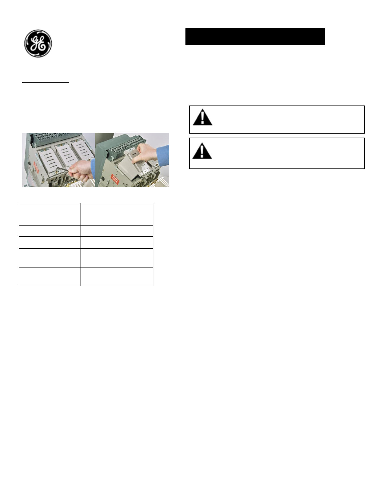
Arc Chute:
Arc chutes are supplied with the Entelliguard
breaker. In cases where it needs the field
replacement, they are supplied as spares.
Figure A Figure B
Arc chamber assembly removal & inspection:
1 Turn the breaker off and discharge the
closing springs by depressing the OFF and
ON buttons in the sequence OFF-ON-OFF.
Verify that the breaker OFF-ON indicator
shows OFF on a green background and
that the charge indicator shows
DISCHARGE on a white background. If
installing in a draw-out type breaker
remove breaker from adaptor (cassette)
before continuing.
2 The breaker should be safely isolated and
fully removed from the cassette (for
drawout breaker)
3 Loosen the M6 mounting screws of arc
chamber to the housings as shown in fig
A
4 Gently lift the Arc chamber assembly as
shown in fig B.
5 Inspect the arc plates and sides of the
moldings for signs of wear or damage
and replace if necessary.
6 Install the arc chamber assembly by
tightening the mounting screws to torque
of 8-10 Nm (5.9 – 7.4 ft-lbs)
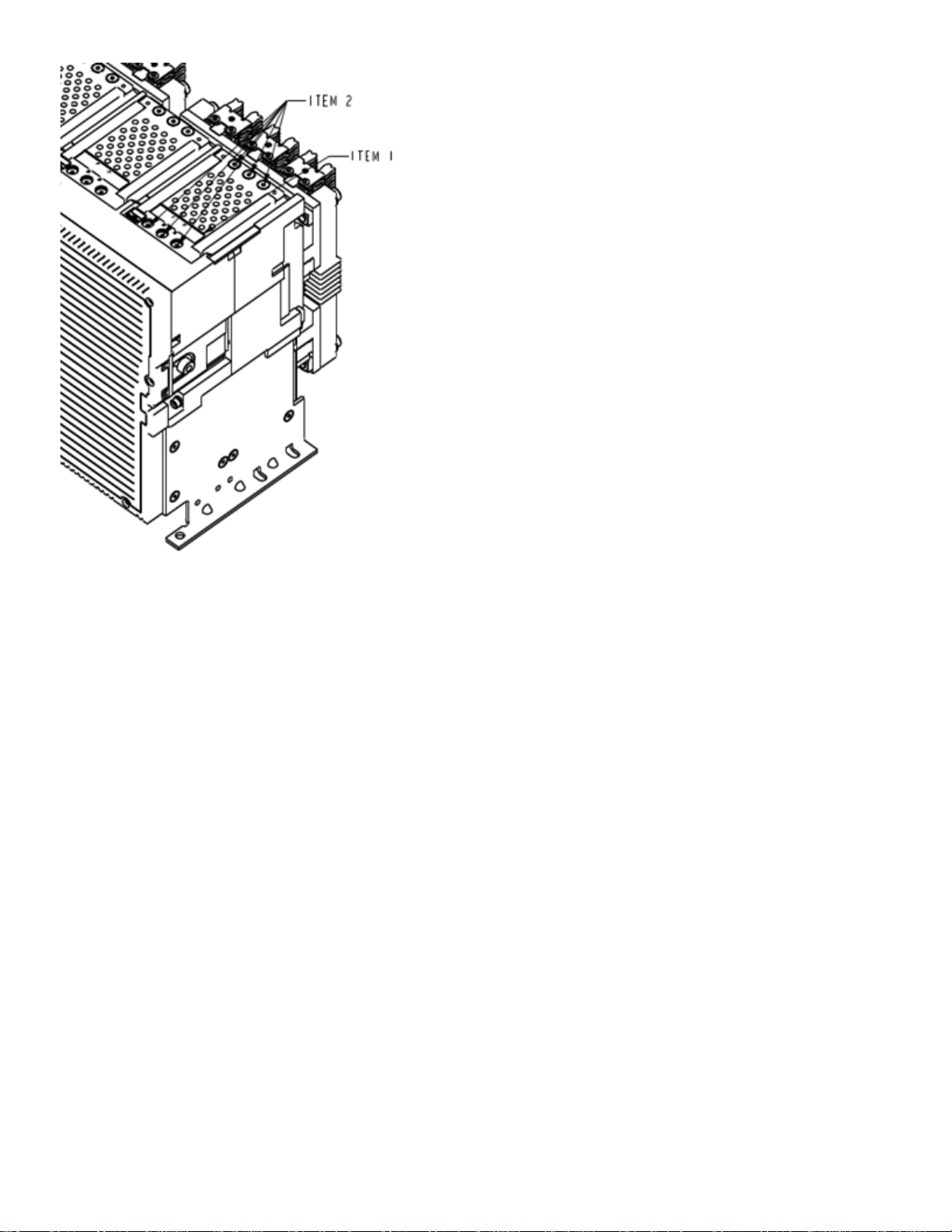
Arc chamber assembly removal & inspection for
Fr-3 200kA:
1 Follow Step 1 and 2
2 Slide out ITEM No 1 and loosen six numbers
of M6 mounting screws of arc chamber to
the housing as shown in figure C
3 Gently lift the Arc chamber assembly as
shown in fig B.
Page 2
2
4 Inspect the arc plates and sides of the
moldings for signs of wear or damage
and replace if necessary.
5 Install the arc chamber assembly by
tightening the mounting screws to
torque of 8-10 Nm (5.9 – 7.4 ft-lbs)
6 Slide in the slider back to original
position
Figure C
Page 3

3
These instructions do not purport to cover all details or variations in equipment nor, to provide contingency to be met in connection
with installation, operation, or maintenance. Should further information be desired, or should particular problems arise which are not
covered sufficiently for the purchaser’s purposes, the matter should be referred to GE.
GE
41 Woodford Ave, Plainville, CT 06062
www.geelectrical.com
© 2009 General Electric Company
 Loading...