

Page 1
g
p
g
quip
p
y
GEH5673 Installation Instructions R03
Spectra Series™ Power Panelboards
Circuit Breakers and Modules
WARNING: Danger of electrical shock or injury.
OFF
Turn
switchboard before workin
ment or removing any component. Do
e
not remove circuit
other component until the power is turned
OFF.
ower ahead of the panelboard or
inside the
rotective devices or an
General
These instructions apply to the following catalog numbers:
• Circuit breaker modules AMC4GB and AMC6GB
• Circuit breaker frames SGDA, SGHA, SGLA and
SGPA
Installation
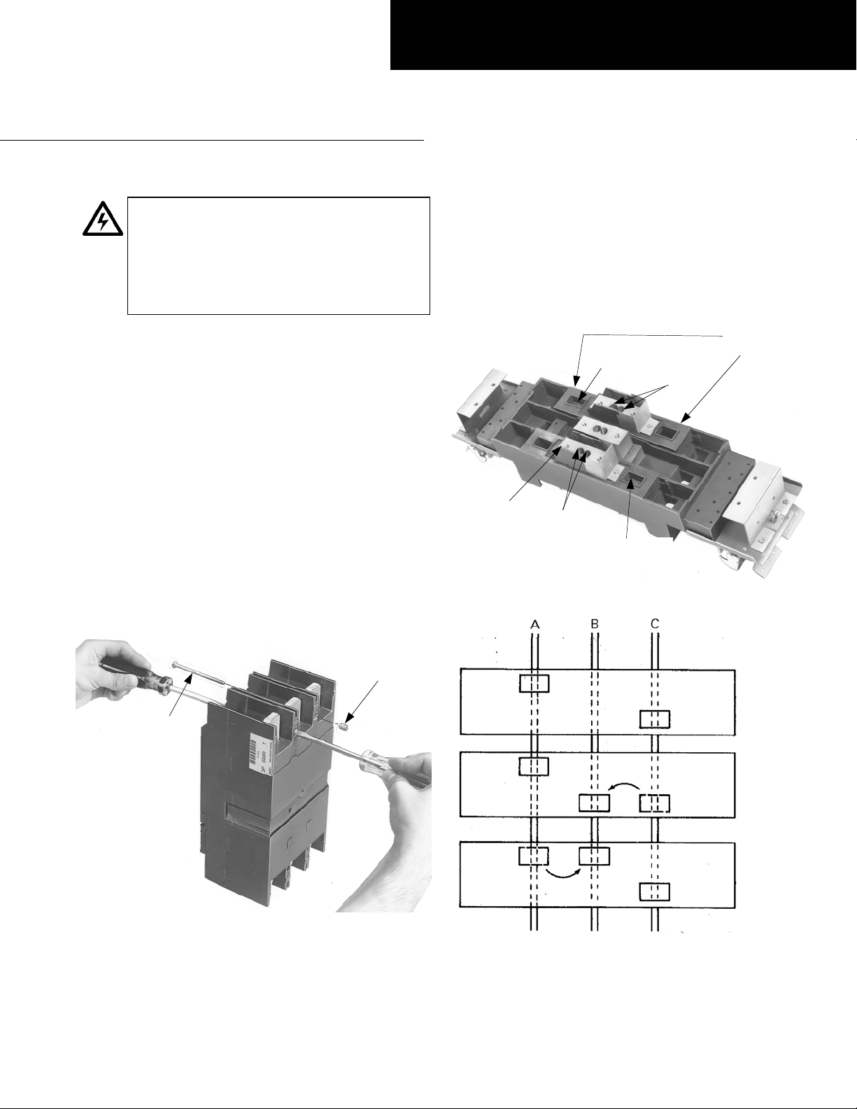
1. Prepare the circuit breaker(s). Before installing the
breakers, install line-end mounting screws into the ON
side of each breaker. Place the breaker vertically on a
flat surface with the ON side up and the OFF side
down, as shown in Figure 1. Install #10-32 pan-head
screws into the ON-side holes on the top of the
breaker. Install #10-32 inserts into the ON-side holes
on the bottom of the breaker. Using two screw drivers,
tighten both the insert and the screw to 20–25 in-lb.
2. Phase balancing for two-pole devices on three-phase
systems. Reposition the bus clip assembly from A or C
phase to B phase, as shown in Figures 2 and 3.
Remove the screws in the bus clip assembly and move
the bus clip to the B-phase position. Fasten the bus
clip assembly in the new location with the slotted hexhead SEMS screws provided and tighten to 27–32 inlb.
A & C
Screws & Bus
Clip Assembly
B Phase
SEMS
Screws
Screws & Bus
Clip Assembly
Figure 2. Repositioning the bus clip assembly.
SEMS
Screws
Phase
#10-32
Insert
#10-32
Screw
Figure 1. Installing line-end mounting screws in the breaker.
A & C Phase
As Received
A & B Phase
B & C Phase
Figure 3. Phase diagram showing locations of bus clips.
Page 2
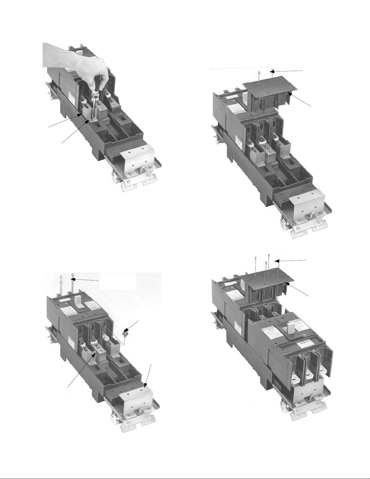
3. Prepare the breaker module (for two breakers only).
Before installing the breakers on the module, remove the
barriers and screws, as shown in Figure 4.
Barrier
Mounting
Screw
Figure 4. Preparing the breaker module for a two-breaker installation.
5. Install the center barrier. The center barrier must be
installed after the breaker has been secured to the
module. Slide the center barrier onto the breaker, as
shown in Figure 6 for a single breaker and in Figure 7 for
two breakers . Secure the center ba rrier with two threa dcutting screws into each breaker and tighten to 10 in-lb.
Figure 8 shows a complete two-breake r installation.
Thread-Cutting
Screws
Center
Barrier
4. Install the circuit breaker(s). Place the Belleville washers
and hex-head screws into the line straps of the circuit
breaker, as shown in Figure 5. Position the ON side of the
breaker on the module, as shown in F igure 5. Align the
hex-head scr ew s in th e stu d -p ost h ol es a nd tigh te n t o 90 –
110 in-lb. Fasten the OFF side of the breaker to the
mounting brackets with the round-head SEMS screws
and flat washers and tighten to 40–50 in-lb. Repeat the
procedure for a second breaker.
Round-Head
SEMS Screw &
Flat Washer
Hex-Head Screw &
Belleville Washer
Mounting
Bracket
Figure 6. Installing the center barrier with one breaker on the module.
Thread-Cutting
Screws
Center
Barrier
Stud Post
Figure 7. Installing the center barrier with two breakers on the module.
Figure 5. Installing the breaker on the module.
Page 3

Figure 8. Completed center barrier installation with two breakers.
6. Install the module. Fully retra ct the latches an d hook
one side of the breake r module to the inter ior rail, as
shown in Figure 9. Release the latch. P ivot the m odule
onto the bus bars and engage the second latch.
Release the la tch. Ti ghten t he latch s crews to 25 in-l b,
as shown in Figure 10.
Latch
Latch
Screw
Figure 10. Securing the module to the interior.
7. Wire the circuits. Refer to the label on the circuit
breaker for the proper tightening torque.
8. Filler plate kits. Install filler plate kit AFP4SGC on the
module.
Attention – Procedure for Aluminum
Terminations
1. Strip the insulation, being careful to not nick the wire.
2. Clean the wire strands with a wire brush.
3. Thoroughly coat the stripped conductor with a
suitable antioxidant compound, such as ALNOX or
PENETROX A13.
4. Insert the conductor and tighten the connector screw
to the indicated torque on the rating label.
Figure 9. Positioning the breaker module on the interior rail.
Latch
Screw
Page 4

g
These instructions do not cover all details or variations in e
quip
y
p
ma
be met in connection with installation, operation, or maintenance. Should further information be desired or should
articular problems arise that are not covered sufficiently for the purchaser’s purposes, the matter should be referred to the
GE Company.
ment nor do they provide for every possible contingency that
GE Industrial Systems
General Electric Company
41 Woodford Ave., Plainville, CT 06062
GEH5673 R03 0701 © 2001 General Electric Company
 Loading...