

Page 1
GE Consumer & Industrial
Electrical Distribution
AF-60 LP™ Micro Drive
Programming Guide
imagination at work
Page 2

Contents
AF-60 LP™ Micro Drive Programming Guide
1. Safety
Safety Instructions 3
Software Version and Approvals 3
General Warning 3
Avoid unintended Start 4
Before Commencing Repair Work 4
2. Introduction
AF-60 LP Micro Drive Model Number System Diagram 5
3. Programming
How to Programme 7
Programming with DCT-10 Set-up Software 7
Programming with the Keypad 7
Status Menu 9
Quick Menu 9
Main Menu 10
4. Parameter Descriptions
3
5
7
11
Parameter group 0: Operation/Display 11
Parameter Group 1: Load/Motor 15
Parameter Group 2: Brakes 22
Parameter Group 3: Reference/Ramps 25
Parameter Group 4: Limits/Warnings 30
Parameter Group 5: Digital In/Out 32
Parameter Group 6: Analogue In/Out 36
Parameter Group 7: Controllers 41
Parameter Group 8: Communication 43
Parameter Group 13: Logic Controller 47
Parameter Group 14: Special Functions 54
Parameter Group 15: Drive Information 56
Parameter Group 16: Data Readouts 58
16-09 Custom Readout 58
5. Parameter Lists
Conversion Index 67
Change during operation 67
63
2-Set-up 67
Type 67
0-** Operation/Display 68
1-** Load/Motor 69
1
Page 3

AF-60 LP™ Micro Drive Programming Guide
2-** Brakes 70
3-** Reference/Ramps 71
4-** Limits/Warnings 72
5-** Digital In/Out 73
6-** Analog In/Out 74
7-** Controllers 75
8-** Comm. and Options 76
13-** Logic Controller 77
14-** Special Functions 78
15-** Drive Information 79
16-** Data Readouts 80
6. Troubleshooting
Alarm, Warning and Extended Status Word 82
Index
81
83
2
Page 4
AF-60 LP™ Micro Drive Programming Guide
1. Safety
1.1.1. High Voltage Warning
The voltage of the frequency converter is dangerous whenever it is connected to mains. Incorrect installation of the motor or frequency
converter may cause damage to the equipment, serious injury or death. Consequently, it is essential to comply with the instructions in this
manual as well as local and national rules and safety regulations.
1.1.2. Safety Instructions
• Make sure the frequency converter is properly connected to earth.
• Do not remove mains connections, motor connections or other power connections while the frequency converter is connected to power.
• Protect users against supply voltage.
• Protect the motor against overloading according to national and local regulations.
• The earth leakage current exceeds 3.5 mA.
• The [OFF] key is not a safety switch. It does not disconnect the frequency converter from mains.
1.1.3. Software Version and Approvals
1
Software Version
Programming Guide
AF-60 LPറ Micro Drive
This Programming Guide can be used for all AF-60 LPറ Micro Drive frequency drives with software version
2.1x.
The software version number can be read in
parameter 15-43.
1.1.4. General Warning
Warning:
Touching the electrical parts may be fatal - even after the equipment has been disconnected from mains.
Also make sure that other voltage inputs have been disconnected (such as external DC bus power supplies).
Be aware that there may be high voltage on the DC link even when the LEDs are turned off.
Before touching any potentially live parts of the frequency converter, wait at least 4 minutes for all sizes.
Shorter time is allowed only if indicated on the nameplate for the specific unit.
3
Page 5
1
AF-60 LP™ Micro Drive Programming Guide
Leakage Current
The earth leakage current from the frequency converter exceeds 3.5 mA. According to IEC 61800-5-1 a reinforced Protective Earth connection
must be ensured by means of a min. 10mm² Cu or an addtional PE wire - with the same cable cross section as the Mains wiring - must be
terminated separately.
Residual Current Device
This product can cause a DC current in the protective conductor. Where a residual current device (RCD) is used for extra protection, only an
RCD of Type B (time delayed) shall be used on the supply side of this product.
Protective earthing of the frequency converter and the use of RCDs must always follow national and local regulations.
Motor overload protection is possible by setting Parameter 1-90 Motor thermal protection to the value Electronic overload trip. For the North
American market: Electronic overload functions provide class 20 motor overload protection, in accordance with NEC.
Installation in high altitudes:
For altitudes above 2 km, please contact GE .
1.1.5. IT Mains
IT Mains
Installation on isolated mains source, i.e. IT mains.
Max. supply voltage allowed when connected to mains: 440 V.
As an option, GE offers line filters for improved harmonics performance.
1.1.6. Avoid unintended Start
While the frequency converter is connected to mains, the motor can be started/stopped using digital commands, bus commands, references or via the drive
Keypad.
• Disconnect the frequency converter from mains whenever personal safety considerations make it necessary to avoid unintended start of any motors.
• To avoid unintended start, always activate the [OFF] key before changing parameters.
1.1.7. Disposal Instruction
Equipment containing electrical components must not be disposed of together with domestic waste.
It must be separately collected with electrical and electronic waste according to local and currently valid legislation.
1.1.8. Before Commencing Repair Work
1.
Disconnect AF-60 LPറ Micro Drive from mains (and external DC supply, if present.)
2. Wait for 4 minutes for discharge of the DC-link.
3. Disconnect DC bus terminals and brake terminals (if present)
4. Remove motor cable
4
Page 6
2. Introduction
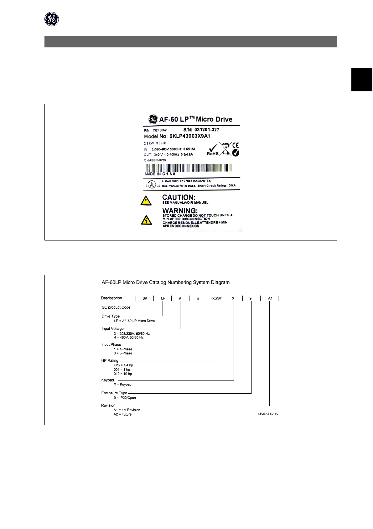
2.1.1. Drive Identification
AF-60 LP™ Micro Drive Programming Guide
Below is an example of the frequency converter nameplate sticker. This sticker is located on the top of each frequency converter and shows the ratings, serial
number, warnings catalog number, and other relevant data for each unit. See following tables for details, how to read the Type code string.
130BA505
Illustration 2.1: This example shows the identification sticker.
2.1.2. AF-60 LP Micro Drive Model Number System Diagram
2
5
Page 7

2
AF-60 LP™ Micro Drive Programming Guide
2.1.3. Symbols
Symbols used in this Programming Guide.
NB!
Indicates something to be noted by the reader.
Indicates a general warning.
Indicates a high-voltage warning.
* Indicates default setting
2.1.4. Abbreviations and Standards
Abbreviations: Terms: SI-units: I-P units:
AWG American wire gauge
Auto Tune Automatic Motor Tuning
rC
I
LIM
rF
FC Frequency Converter
Frequency Hz Hz
kHz Kilohertz
LCP Local Control Panel
mA Milliampere
ms Millisecond
min Minute
MCT Motion Control Tool
M-TYPE Motor Type Dependent
Nm Newton Metres in-lbs
I
M,N
f
M,N
P
M,N
U
M,N
par. Parameter
PELV Protective Extra Low Voltage
Pressure Pa = N/m² psi, psf, ft of water
I
INV
RPM Revolutions Per Minute
SR Size Related
Temperature ˚C ˚F
T
LIM
Acceleration
Celsius
Current A Amp
Current limit
Energy J = N·m ft-lb, Btu
Fahrenheit
Nominal motor current
Nominal motor frequency
Nominal motor power
Nominal motor voltage
Power W Btu/hr, hp
Rated Inverter Output Current
Time s s,hr
Torque limit
Voltage V V
m/s
2
ft/s
2
Table 2.2: Abbreviation and Standards table .
6
Page 8
3. Programming
3.1. How to Programme
3.1.1. Programming with DCT-10 Set-up Software
AF-60 LP™ Micro Drive Programming Guide
The frequency converter can be programmed from a PC via RS485 com-port by installing the DCT-10 Set-up Software.
This software can be downloaded from the GE Web site: www.geelectrical.com/drives
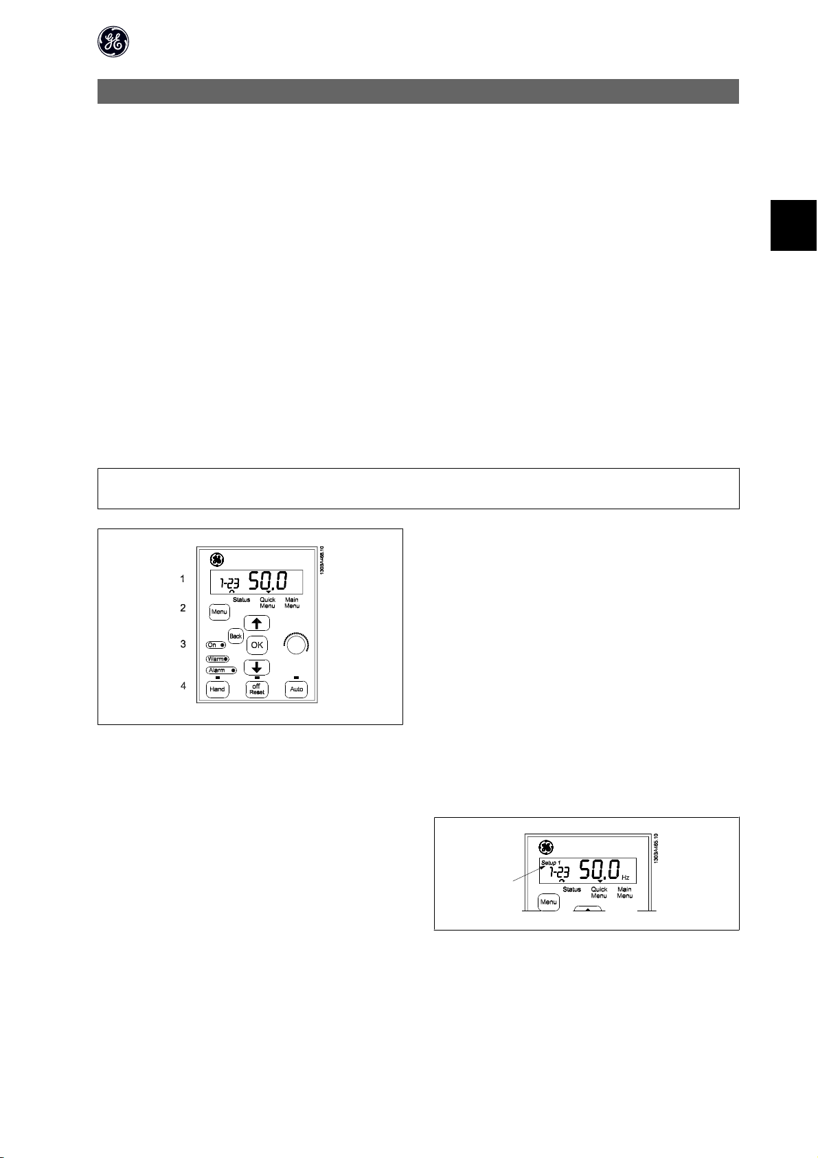
3.1.2. Programming with the Keypad
The Keypad is divided into four functional groups:
1. Numeric display.
2. Menu key.
3. Navigation keys.
4. Operation keys and indicator lights (LEDs).
NB!
Parameters should be changed in numerical order. Certain parameter values are affected by preceding changes.
3
Illustration 3.1: Keypad with potentiometer
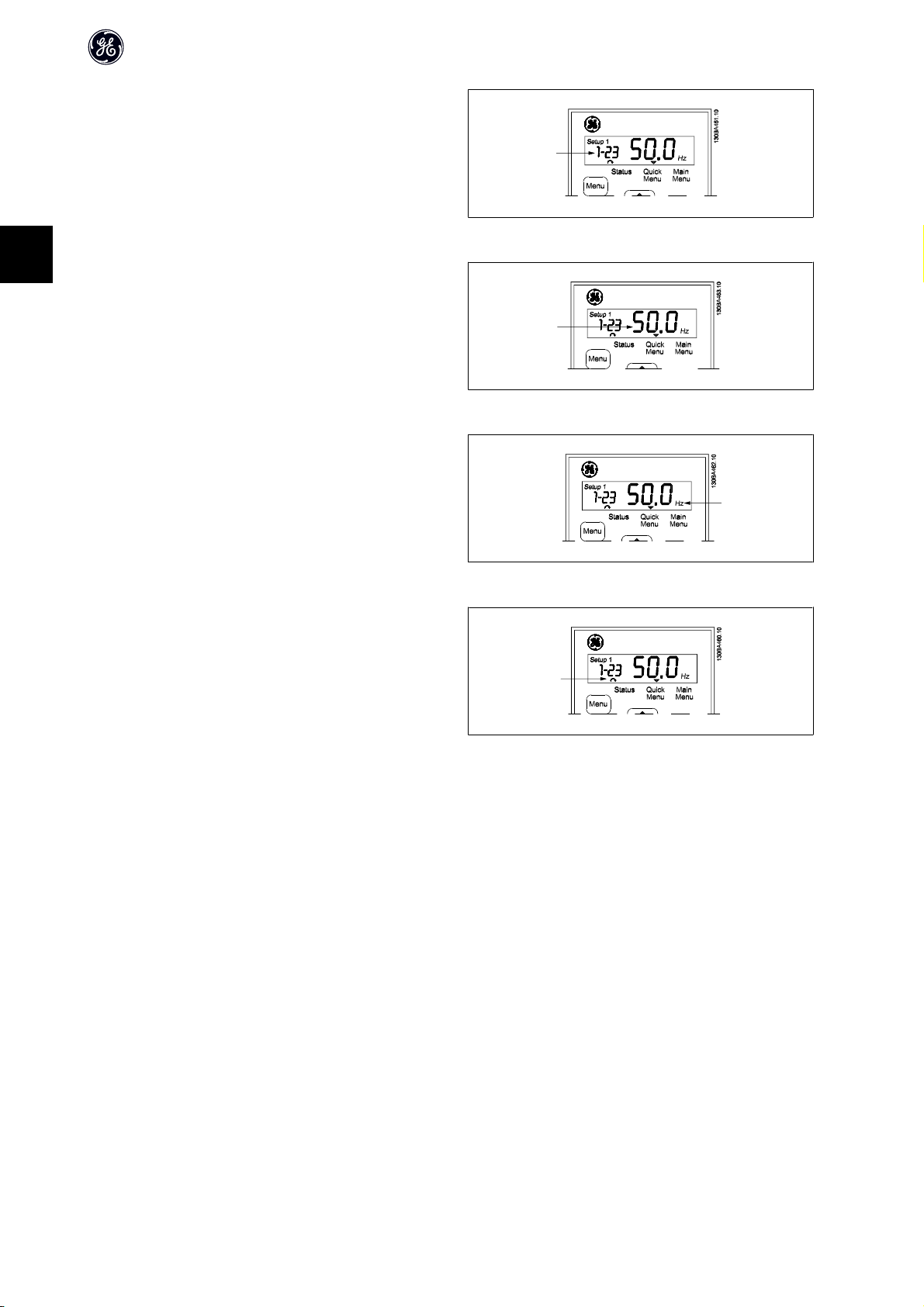
The display:
A number of information can be read from the display.
Set-up number shows the active set-up and the edit set-up. If the same set-
up acts as both active and edit set-up, only that set-up number is shown
(factory setting).
When active and edit set-up differ, both numbers are shown in the display
(Setup 12). The number flashing, indicates the edit set-up.
Illustration 3.3: Indicating Set-up
7
Page 9
3
AF-60 LP™ Micro Drive Programming Guide
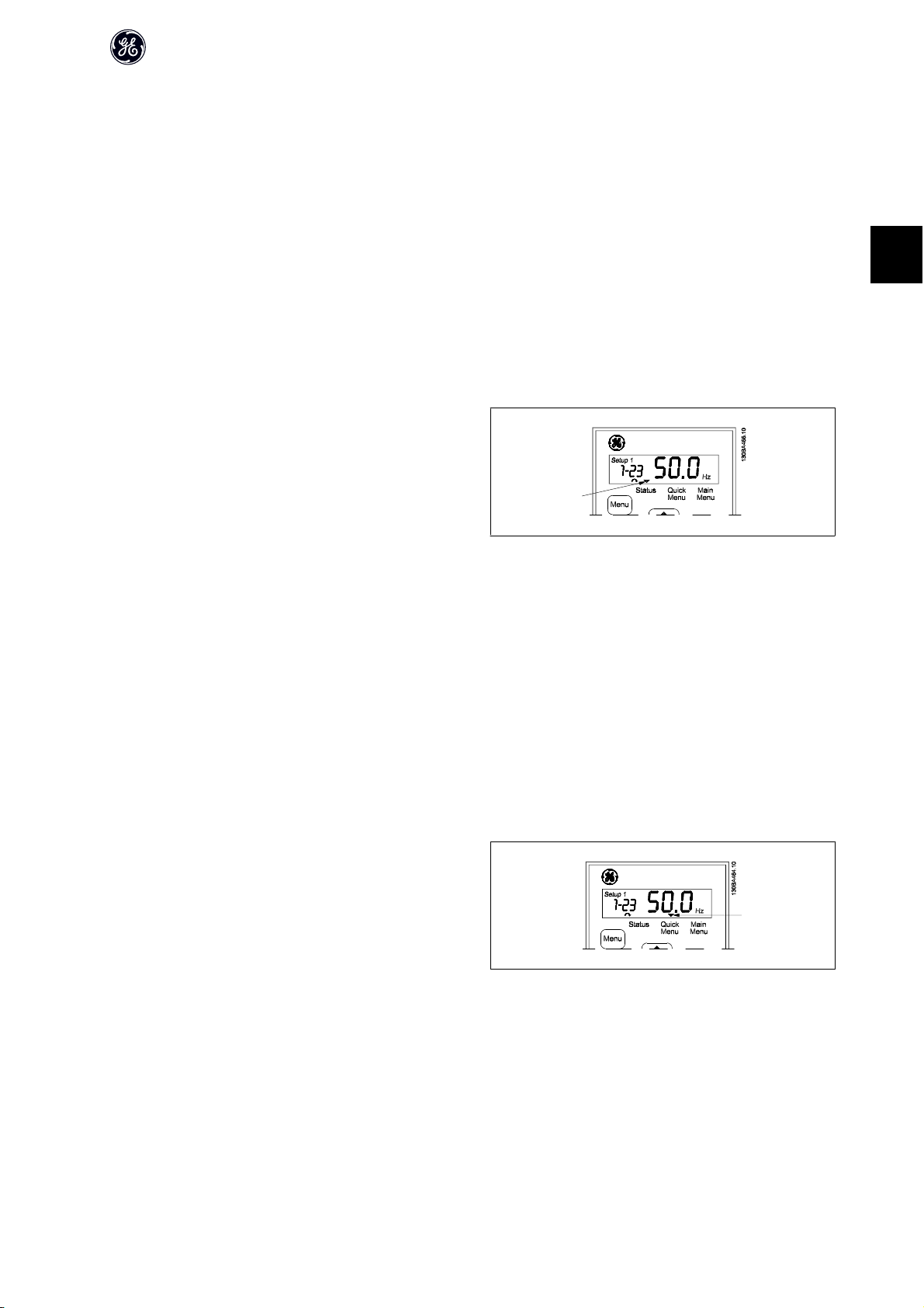
The small digits to the left are the selected parameter number.
Illustration 3.4: Indicating selected par. no.
The large digits in the middle of the display show the value of the selected
parameter.
Illustration 3.5: Indicating value of selected par.
The right side of the display shows the unit of the selected parameter. This
can be either Hz, A, V, kW, HP, %, s or RPM.
Illustration 3.6: Indicating unit of selected par.
Motor direction is shown to the bottom left of the display - indicated by a
small arrow pointing either clockwise or counterclockwise.
Illustration 3.7: Indicating motor direction
Use the [MENU] key to select one of the following menus:
Status Menu:
The Status Menu is either in Readout Mode or Hand Mode. In Readout Mode the value of the currently selected readout parameter is shown in the display.
In Hand Mode the local Keypad reference is displayed.
Quick Menu:
Displays Quick Menu parameters and their settings. Parameters in the Quick Menu can be accessed and edited from here. Most applications can be run by setting
the parameters in the Quick Menus.
Main Menu:
Displays Main Menu parameters and their settings. All parameters can be accessed and edited here. A parameter overview is found later in this manual.
Indicator lights:
• Green LED: The frequency converter is on.
• Yellow LED: Indicates a warning. Please see section Troubleshooting
• Flashing red LED: Indicates an alarm. Please see section Troubleshooting
8
Page 10
AF-60 LP™ Micro Drive Programming Guide
Navigation Keys:
[Back]: For moving to the previous step or layer in the navigation structure.
Arrows [Ⴃ] [Ⴍ]: For maneuvering between parameter groups, parameters and within parameters.
[OK]: For selecting a parameter and for accepting changes to parameter settings.
Operation Keys:
A yellow light above the operation keys indicates the active key.
[Hand ]: Starts the motor and enables control of the frequency converter via the Keypad.
[Off/Reset]: The motor stops except in alarm mode. In that case the motor will be reset.
[Auto ]: The frequency converter is controlled either via control terminals or serial communication.
[Potentiometer] Keypad: The potentiometer works in two ways depending on the mode in which the frequency converter is running.
In Auto Mode the potentiometer acts as an extra programmable analog input.
In Hand Mode the potentiometer controls local reference.
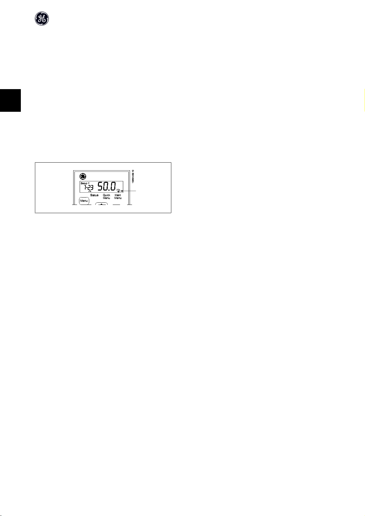
3.2. Status Menu
After power up the Status Menu is active. Use the [MENU] key to toggle be-
tween Status, Quick Menu and Main Menu.
Arrows [Ⴃ] and [Ⴍ] toggles between the choices in each menu.
3
The display indicates the status mode with a small arrow above “Status”.
Illustration 3.8: Indicating Status mode
3.3. Quick Menu
The Quick Menu gives easy access to the most frequently used parameters.
1. To enter the Quick Menu, press [MENU] key until indicator in display is placed above Quick Menu.
2.
Use [Ⴃ] [Ⴍ] to select either QM1 or QM2, then press [OK].
3.
Use [Ⴃ] [Ⴍ] to browse through the parameters in the Quick Menu.
4. Press [OK] to select a parameter.
5.
Use [Ⴃ] [Ⴍ] to change the value of a parameter setting.
6. Press [OK] to accept the change.
7. To exit, press either [Back] twice to enter Status, or press [Menu] once to enter Main Menu.
Illustration 3.9: Indicating Quick Menu mode
9
Page 11
3
3.4. Main Menu
The Main Menu gives access to all parameters.
1. To enter the Main Menu, press [MENU] key until indicator in display
is placed above Main Menu.
2.
Use [Ⴃ] [Ⴍ] to browse through the parameter groups.
3. Press [OK] to select a parameter group.
4.
Use [Ⴃ] [Ⴍ] to browse through the parameters in the specific group.
5. Press [OK] to select the parameter.
6.
Use [Ⴃ] [Ⴍ] to set/change the parameter value.
7. Press [OK] to accept the value.
8. To exit, press either [Back] twice to enter Quick Menu, or press
[Menu] once to enter Status.
AF-60 LP™ Micro Drive Programming Guide
Illustration 3.10: Indicating Main Menu mode
10
Page 12

AF-60 LP™ Micro Drive Programming Guide
4. Parameter Descriptions
4.1. Parameter group 0: Operation/Display
0-03 Regional Settings
Option: Function:
In order to meet the needs for different default settings in different parts of the world, par. 0-03, Regional Settings, is
implemented in the frequency converter. The selected setting influences the default setting of the motor nominal
frequency.
[0 ] International Sets default of par. 1-23, Motor Frequency, to 50 Hz, shows par. 1-20 in kW.
*
[1]
0-04 Operating State at Power-up (Hand Mode)
Option: Function:
US Sets default of par. 1-23, Motor Frequency, to 60 Hz, shows par. 1-20 in HP.
NB!
This parameter cannot be adjusted while motor runs.
This parameter controls whether or not the frequency converter should start running the motor when powering up
after a power down in Hand mode.
NB!
If Keypad with potentiometer is mounted, reference is set according to actual potentiometer value.
4
[0] Resume Frequency converter starts in same Hand or Off State as when powered off.
Local reference is stored and used after power-up.
*
[1]
[2] Forced Stop, Ref=0 Frequency converter powers up in Off State meaning that motor is stopped after power up.
Forced Stop, Ref=Old Frequency converter powers up in Off State meaning that motor is stopped after power up.
Local reference is stored and used after power-up.
Local reference is set to 0. Thus motor will not start running before local reference has been increased.
4.1.1. 0-1* Set-up Handling
User defined parameters and miscellaneous external inputs (eg. bus, Keypad, analog/digital inputs, feedback, etc.) controls the functionality of the frequency
converter.
A complete set of all parameters controlling the frequency converter is called a set-up. The frequency converter contains 2 set-ups, Set-up1 and Set-up 2.
Furthermore, a fixed set of factory settings can be copied into one or more set-ups.
Some of the advantages of having more than one set-up in the frequency converter are
• Run motor in one set-up (Active Set-up) while updating parameters in another set-up (Edit Set-up)
• Connect various motors (one at a time) to frequency converter. Motor data for various motors can be placed in different set-ups.
• Rapidly change settings of frequency converter and/or motor while motor is running (eg. ramp time or preset references) via bus or digital inputs.
The Active Set-up can be set as Multi Set-up where the active set-up is selected via input on a digital input terminal and/or via the bus control word.
NB!
FactorySet-up cannot be used as Active Set-up.
0-10 Active Set-up
Option: Function:
Active Set-up controls the motor.
Shifts between set-ups can only happen when
11
Page 13

AF-60 LP™ Micro Drive Programming Guide
•the motor is coasted
OR
• the set-ups between which the shift happens are linked to each other (see par. 0-12, Linked Set-ups).
If changing between set-ups that are not linked, the change will not happen before motor is coasted.
NB!
The motor is only considered stopped when it is coasted.
4
[1 ]
*
[2] Set-up 2 Set-up 2 is active.
[9] Multi Set-up Select the active set-up via digital input and/or bus, see par. 5-1* choice [23].
Set-up 1 Set-up 1 is active.
0-11 Edit Set-up
Option: Function:
The Edit Set-up is for updating parameters in the frequency converter from either Keypad or bus. It can be identical
or different from the Active Set-up.
All set-ups can be edited during operation, independently of the active set-up.
*
[1 ]
[2] Set-up 2 Update parameters in Set-up 2.
[9] Active Set-up Update parameters in set-up selected as Active Set-up (see par. 0-10).
Set-up 1 Update parameters in Set-up 1.
0-12 Link Set-ups
Option: Function:
The link ensures synchronizing of the “not changeable during operation” parameter values enabling shift from one
set-up to another during operation.
If the set-ups are not linked, a change between them is not possible while the motor is running. Thus the set-up change
does not occur until the motor is coasted.
[0] Not linked Leaves parameters unchanged in both set-ups and cannot be changed while motor runs.
[1 ]
*
Linked Copy parameters “not changeable during operation” parameter values into presently selected Edit Set-up.
NB!
This parameter cannot be changed while motor runs.
4.1.2. 0-31 Custom Readout Min Scale
0-31 Custom Readout Min Scale
Range: Function:
0.00* [0.00 – 9999.00 ]
It is possible to create a customized readout related to the output frequency of the unit. The value entered in par. 0-31
will be shown at 0 Hz. The readout can be shown in the LCP display when in Status Mode or it can be read in par. 16-09
4.1.3. 0-32 Custom Readout Max Scale
0-32 Custom Readout Max Scale
Range: Function:
100.0* [0.00 – 9999.00]
It is possible to create a customized readout related to the output frequency of the unit. The value entered in par. 0-32
will be shown at the frequency programmed in par. 4-14 Motor Speed High Limit. The readout can be shown in the LCP
display when in Status Mode or it can be read in par. 16-09
4.1.4. 0-4* Keypad
The frequency converter can operate in the following three modes: Hand, Off and Auto.
Hand: The frequency converter is locally operated and does not allow any remote control. By activating Hand a start signal is given.
OFF: The frequency converter stops with a normal stop ramp. When Off is chosen the frequency converter can only be started by pressing either Hand or Auto
on the Keypad.
12
Page 14

Auto: In Auto-mode the frequency converter can be remote controlled (bus/digital).
0-40 [Hand ] Key on Keypad
Option: Function:
[0] Disabled Hand key has no function.
[1 ]
*
Enabled Hand key is functional.
0-41 [Off/Reset] Key on Keypad
Option: Function:
[0] Disable Off/Reset Off/reset key has no function.
*
[1 ]
[2] Enable Reset Only Reset only. Stop (Off) function is disabled.
Enable Off/Reset Stop signal and reset of any faults.
0-42 [Auto ] Key on Keypad
Option: Function:
[0] Disabled Auto key has no function.
[1 ]
*
Enabled Auto key is functional.
4.1.5. 0-5* Copy/Save
AF-60 LP™ Micro Drive Programming Guide
4
0-50 Keypad Copy
Option: Function:
The detachable Keypad of the frequency converter can be used for storing setups, and thus for transferring data when
moving parameter settings from one frequency converter to another.
NB!
Keypad Copy can only be activated from the Keypad and ONLY when the motor is coasted.
[1] All to Keypad Copy all setups from the frequency converter into the Keypad.
[2] All from Keypad Copy all setups from Keypad to frequency converter.
[3] Size indep. from Keypad Copy non motor size dependent data from Keypad to frequency converter
0-51 Set-up Copy
Option: Function:
Use this function to copy a set-up content into the Edit Set-up.
In order to be able to make a set-up copy ensure that
• the motor is coasted
• par. 0-10, Active Set-up, is set to either Set-up 1 [1] or Set-up 2 [2]
NB!
The keyboard/parameter database are blocked while Set-up Copy is running.
[0 ]
*
[1] Copy from Set-up 1 Copy from Set-up 1 to edit set-up chosen in par. 0-11, Edit Set-up.
[2] Copy from Set-up 2 Copy from Set-up 2 to edit set-up chosen in par. 0-11, Edit Set-up.
[9] Copy from Factory Set-upCopy from Factory Settings to edit set-up chosen in par. 0-11, Edit set-up.
No Copy Copy function is inactive
4.1.6. 0-6* Password
0-60 (Main) Menu Password
Range: Function:
Use password for protection against unintended change of sensitive parameters, eg. motor parameters.
Password protected parameters can always be read, but cannot be edited without entering the password.
13
Page 15

AF-60 LP™ Micro Drive Programming Guide
4
0* [0 - 999]
NB!
Pressing buttons [MENU], [OK] and down will unlock the password. This will automatically enter the parameter editing screen in Quick Menu or Main Menu.
Enter the password for access to Main Menu via the [Main Menu] key. Select the number that should allow for changing
other parameter values. 0 means there is no password.
14
Page 16

4.2. Parameter Group 1: Load/Motor
1-00 Configuration Mode
Option: Function:
Use this parameter for selecting the application control principle to be used when a Remote Reference is active.
NB!
Changing this parameter will reset parameters 3-00, 3-02 and 3-03 to their default values.
NB!
This parameter cannot be adjusted while motor runs.
AF-60 LP™ Micro Drive Programming Guide
[0 ]
*
[3] Process Closed Loop Enables process closed loop control. See par. group 7-3* for further information on PI-controller.
Speed Open Loop For normal speed control (References).
When running in process closed loop, par. 4-10 Motor Speed Direction must be set to Clockwise [0]
1-01 Motor Control Principle
Option: Function:
[0] U/f Is used for parallel connected motors and/or special motor applications. The U/f settings are set in parameters 1-55
and 1-56.
NB!
When running U/f control slip- and load compensations are not included.
[1]
*
Advanced Vector Con-
trol
Normal running mode, including slip- and load compensations.
1-03 Torque Characteristics
Option: Function:
With more torque characteristics it is possible to run low energy consuming, as well as high torque applications.
*
[0 ]
[2] Energy Savings This function automatically optimizes energy consumption in centrifugal pump and fan applications. See par. 14-41
Constant Torque Motor shaft output provides constant torque under variable speed control.
Energy Savings Minimum Magnetisation.
1-05 Hand Mode Configuration
Option: Function:
This parameter is only relevant when parameter 1-00 Configuration Mode is set to Process Closed Loop [3]. The pa-
rame ter is use d for dete rmining the refer ence or setpoint h andling w hen changing from Auto Mode to Hand Mo de on
the Keypad.
[0] Speed Open Loop In Hand Mode the drive always runs in Open Loop configuration regardless of setting in par. 1-00 Configuration
Mode. Local potentiometer (if present) or Arrow up/down determines output frequency limited by Motor Speed High/
Low Limit (parameters 4-14 and 4-12).
[2]
*
As configuration in par.
1-00
If par. 1-00 Configuration Mode is set to Open Loop [1] function is as described above.
If par. 1-00 is set to Process Closed Loop [3] changing from Auto mode to Hand mode results in a setpoint change via
local potentiometer or Arrow up/down. The change is limited by Reference Max/Min (parameters 3-02 and 3-03).
4
4.2.1. 1-2* Motor Data
Enter the correct motor nameplate data (power, voltage, frequency, current and speed).
Run Auto Tune, see par. 1-29.
Factory settings for advanced motor data, par. 1-3*, are automatically calculated.
NB!
Parameters in parameter group 1.2* cannot be adjusted while motor runs.
15
Page 17

AF-60 LP™ Micro Drive Programming Guide
4
1-20 Motor Power [kW]/[HP] (P
m.n
)
Option: Function:
Enter motor power from nameplate data.
Two sizes down, one size up from nominal AF-60 LPറ rating.
[1] 0.09 kW/0.12 HP
[2] 0.12 kW/0.16 HP
[3] 0.18kW/0.25 HP
[4] 0.25 kW/0.33 HP
[5] 0.37kW/0.50 HP
[6] 0.55 kW/0.75 HP
[7] 0.75 kW/1.00 HP
[8] 1.10 kW/1.50 HP
[9] 1.50 kW/2.00 HP
[10] 2.20 kW/3.00 HP
[11] 3.00 kW/4.00 HP
[12] 3.70 kW/5.00 HP
[13] 4.00 kW/5.40 HP
[14] 5.50 kW/7.50 HP
[15] 7.50 kW/10.0 HP
[16] 11.00 kW/15.00 HP
NB!
Changing this parameter affects par. 1-22 to 1-25, 1-30, 1-33 and 1-35.
1-22 Motor Voltage (U
m.n
)
Range: Function:
230/400 V [50 - 999 V] Enter motor voltage from nameplate data.
1-23 Motor Frequency (f
m.n
)
Range: Function:
60 Hz* [20-400 Hz]
1-24 Motor Current (I
m.n
Enter motor frequency from nameplate data.
)
Range: Function:
M-type dependent* [0.01 - 26.00 A]
1-25 Motor Nominal Speed (n
Enter motor current from nameplate data.
)
m.n
Range: Function:
M-type Dependent* [100 - 9999 RPM]
Enter motor nominal speed from nameplate data.
1-29 Auto Tune
Option: Function:
Use Auto Tune to optimize motor performance.
NB!
This parameter cannot be changed while motor runs.
16
1. Stop the frequency converter – make sure motor is at standstill
2. Choose [2] Enable Auto Tune
3. Apply start signal
– Via Keypad: Press Hand
Page 18
AF-60 LP™ Micro Drive Programming Guide
- Or in Remote On mode: Apply start signal on terminal 18
[0]
*
[2] Enable Auto Tune Auto Tune function starts running.
Off Auto Tune function is disabled.
NB!
To gain optimum tuning of frequency converter, run Auto Tune on a cold motor.
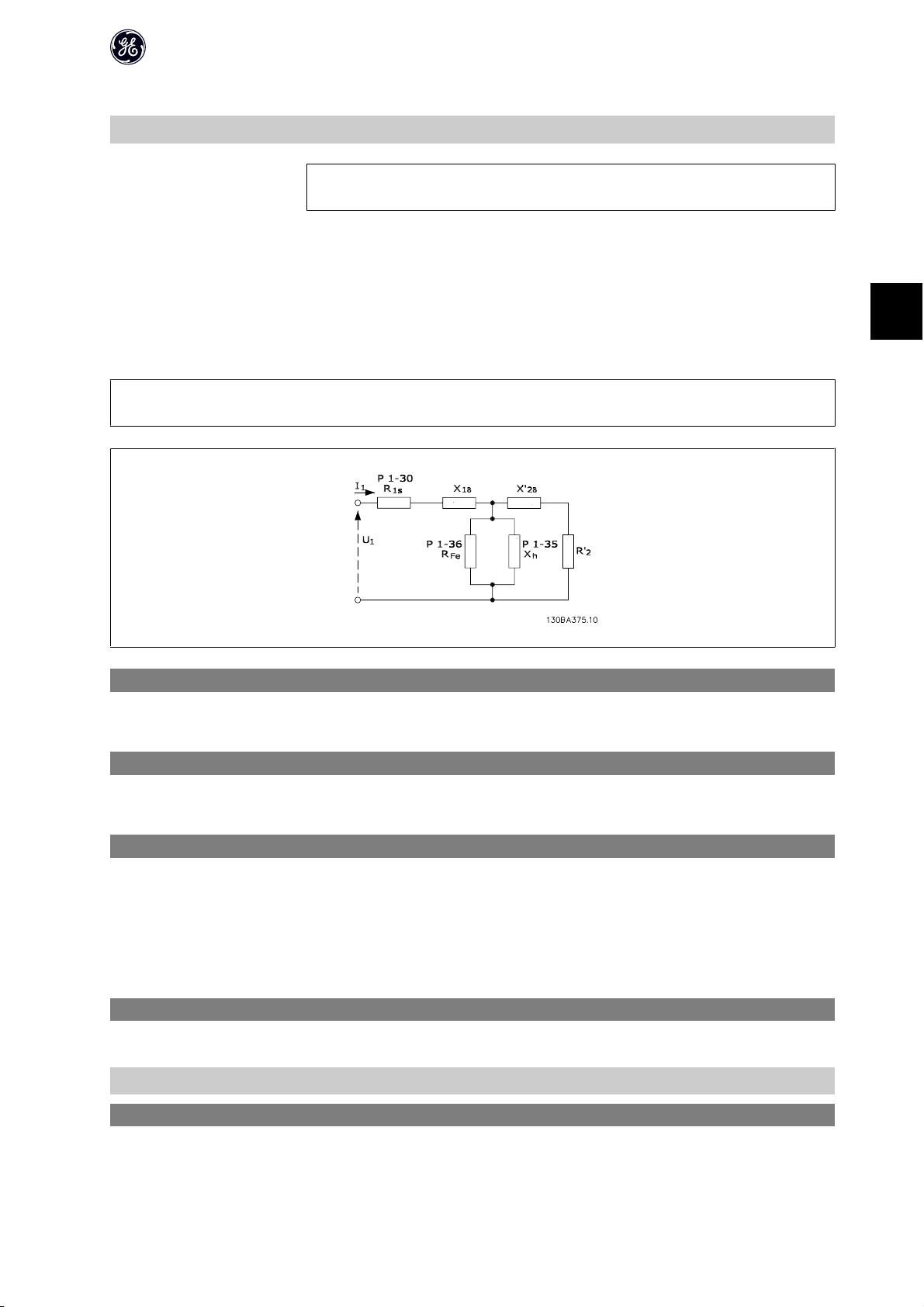
4.2.2. 1-3* Adv. Motor Data
Adjust advanced motor data using one of these methods:
1. Run Auto Tune on cold motor. Frequency converter measures value from motor.
2. Enter X
3. Use R
NB!
These parameters cannot be changed while motor runs.
value manually. Obtain value from motor supplier.
1
, X1, and X2default setting. Frequency converter establishes setting based on motor nameplate data.
s
4
1-30 Stator Resistance (Rs)
Range: Function:
Depending on motor data* [Ohm]
Set stator resistance value.
1-33 Stator Leakage Reactance (X1)
Range: Function:
Depending on motor data* [Ohm]
Set stator leakage reactance of motor.
1-35 Main Reactance (X2)
Range: Function:
Depending on motor data* [Ohm]
Set motor main reactance.
4.2.3. 1-5* Load Independent Setting
This parameter group is for setting the load independent motor settings.
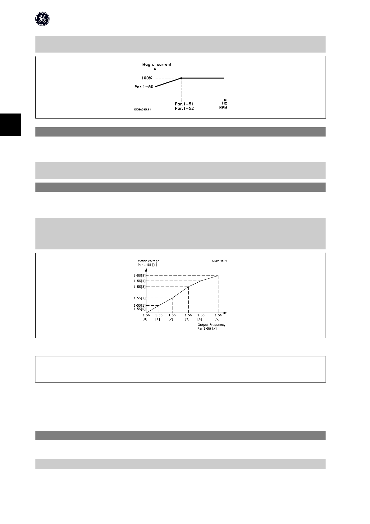
1-50 Motor Magnetization at Zero Speed
Range: Function:
This parameter enables different thermal load on motor when running at low speed.
*
[ 0 - 300%]
100 %
1-52 Min. Speed Normal Magnetizing [Hz]
Range: Function:
Enter a percentage of rated magnetizing current. If setting is too low, motor shaft torque may be reduced.
Use this parameter along with par. 1-50, Motor Magnetizing at Zero Speed.
17
Page 19
AF-60 LP™ Micro Drive Programming Guide
4
0.0 Hz* [0.0 - 10.0 Hz]
Set frequency required for normal magnetizing current. If frequency is set lower than motor slip frequency, par. 1-50,
Motor Magnetizing at Zero Speed is inactive.
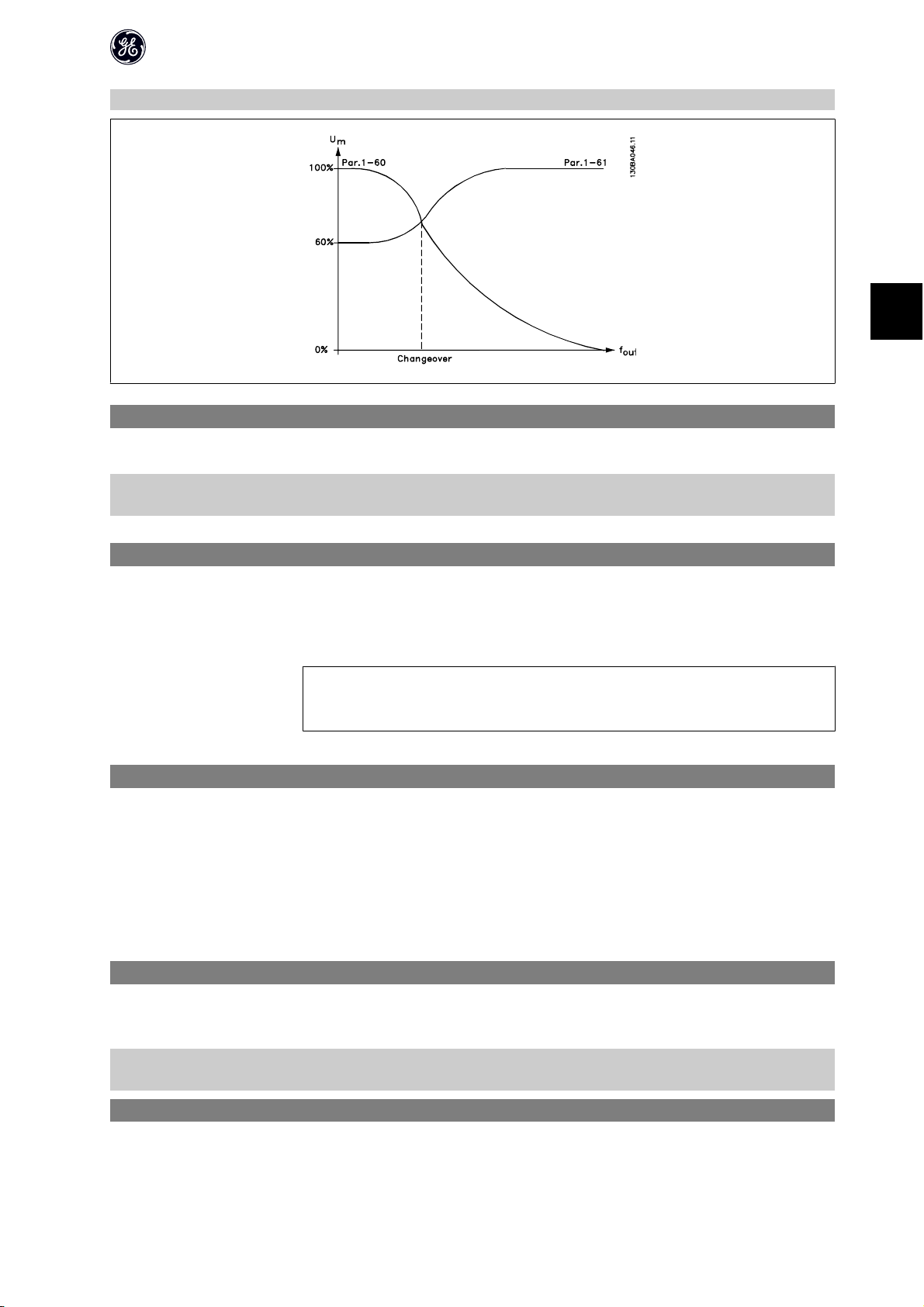
1-55 U/f Characteristic - U
Range: Function:
This parameter is an array parameter [0-5] and is only functional when par. 1-01, Motor Control Principle is set to U/
f [0].
0.0 V
*
[0.0 - 999.9 V]
Enter voltage at each frequency point to manually form a U/f characteristic matching motor. Frequency points are
defined in par. 1-56, U/f characteristics - F.
1-56 U/f Characteristic - F
Range: Function:
This parameter is an array parameter [0-5] and is only functional when par. 1-01, Motor Control Principle is set to U/f
[0].
0.0 Hz
*
[0.0 - 1000.0 Hz]
Enter frequency points to manually form a U/f characteristic matching motor. Voltage at each point is defined in par.
1-55, U/f Characteristic - U.
Make a U/f characteristic based on 6 definable voltages and frequencies, see below figure.
Simplify U/f characteristics by merging 2 or more points (voltages and frequencies), respectively, are set equal.
Illustration 4.1: Fig. 1 U/f characteristics
NB!
For par. 1-56 the following applies
[0] ู [1] ู [2] ู [3] ู [4] ู [5]
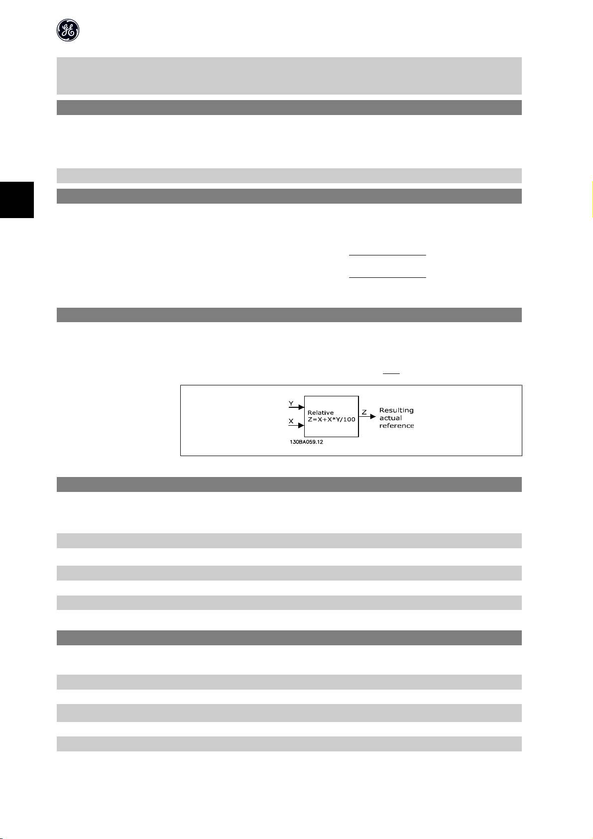
4.2.4. 1-6* Load Dependent setting
Parameters for adjusting the load dependent motor settings.
1-60 Low Speed Load Compensation
Range: Function:
Use this parameter to gain optimum U/f characteristic when running at low speed.
100 %* [0-199 %]
Enter percentage in relation to load when motor runs at low speed.
18
Page 20
Change-over point is automatically calculated based on motor size.
1-61 High Speed Load Compensation
Range: Function:
Use this parameter to obtain optimum load compensation when running at high speed.
100 %
*
[0 - 199 %]
Enter percentage to compensate in relation to load when motor runs at high speed.
Change-over point is automatically calculated based on motor size.
AF-60 LP™ Micro Drive Programming Guide
4
1-62 Slip Compensation
Range: Function:
100 %* [-400 - 399 %]
Compensation for load dependent motor slip.
Slip compensation is calculated automatically based on rated motor speed, n
and the 4 pole 1800 RPM motor has an actual nameplate RPM of 1750 RPM, then 50 RPM is added to the output
frequency by the drive.
NB!
This function is only active when par. 1-00, Configuration Mode, is set to Speed Open Loop [0], and when par. 1-01,
Motor Control Principle, is set to Advanced Vector Control [1].
. Example: if par. 1-62 is set to 100%
M,N
1-63 Slip Compensation Time
Range: Function:
0.10 s [0.05 - 5.00 s] Enter slip compensation reaction speed. A high value results in slow reaction whereas a low value results in quick
reaction.
If low-frequency resonance problems arise, use longer time setting.
4.2.5. 1-7* Start Adjustments
Considering the need for various start functions in different applications, it is possible to select a number of functions in this parameter group.
1-71 Start Delay
Range: Function:
The start delay defines the time to pass from a start command is given until the motor starts accelerating.
Setting start delay to 0.0 sec. disables Start Function, [1-72], when start command is given.
0.0 s
*
[0.0 - 10.0 s]
Enter the time delay required before commencing acceleration.
Par. 1-72 Start Function is active during Start delay time .
1-72 Start Function
Option: Function:
[0] DC Hold/Delay Time Motor is energized with DC holding current (par. 2-00) during start delay time.
19
Page 21

AF-60 LP™ Micro Drive Programming Guide
[1] DC Brake/Delay Time Motor is energized with DC braking current (par. 2-01) during start delay time.
[2]
*
1-73 Start Mode
Option: Function:
Coast/Delay Time Drive is coasted during start delay time ( Driveoff).
The Start Mode parameter is used to catch a spinning motor after eg. mains drop-out.
This function is not suitable for hoisting applications.
4
[0]
*
[1] Enabled Frequency converter enabled to catch spinning motor.
Disabled Catch a spinning load disabled.
NB!
When catch a spinning load is enabled par. 1-71, Start Delay, and par. 1-72, Start Function, have no function.
4.2.6. 1-8* Stop Adjustments
To meet the need for various stop functions in different application these parameters offer some special stop features for the motor.
1-80 Function at Stop
Option: Function:
The selected function at stop is active in following situations:
• Stop command is given and output speed is ramped down to Min. Speed for Activating Functions at Stop.
• Start command is removed (standby), and output speed is ramped down to Min. Speed for Activating Functions
at Stop.
• DC-brake command is given, and DC-brake time has passed
• While running and calculated output speed is below Min. Speed for Activating Functions at Stop.
*
[0]
[1] DC hold The motor is energized with a DC current. See par. 2-00 DC Hold Current for more information.
1-82 Min. Speed For Function at Stop [Hz]
Range: Function:
0.0 Hz* [0.0 - 20.0 Hz]
Coast The drive is coasted.
Set the speed at which to activate par. 1-80 Function at Stop.
4.2.7. 1-9* Motor Temperature
With an estimated motor temperature monitor the frequency converter is able to estimate motor temperature without having a thermistor mounted. It is thus
possible to receive a warning or an alarm, if motor temperature exceeds upper operational limit.
1-90 Motor Thermal Protection
Option: Function:
Using Electronic Overload the motor temperature is calculated based on frequency, speed and time. GE recommends
using The Electronic Overload function, if a thermistor is not present.
NB!
Electronic Overload calculation is based on motor data from group 1-2*.
[0]
*
[1] Thermistor Warning A thermistor connected to either digital or analog input gives a warning if upper limit of motor temperature range is
[2] Thermistor Trip A thermistor connected to either digital or analog input gives an alarm and makes the frequency converter trip if upper
No Protection Disables temperature monitoring.
exceeded, (see par. 1-93, Thermistor Resource).
limit of motor temperature range is exceeded, (see par. 1-93, Thermistor Resource.
20
Page 22

AF-60 LP™ Micro Drive Programming Guide
[3] Electronic Overload
Warning
[4] Electronic Overload Trip If 90% of calculated upper limit of motor temperature range is exceeded, an alarm occurs and frequency converter
NB!
When the Electronic Overload function has been selected the drive will store the recorded temperature at power down and this temperature will resume at
power up regardless of the elapsed time. Changing par. 1-90 back to [0] No Protection will reset the recorded temperature.
If calculated upper limit of motor temperature range is exceeded, a warning occurs.
trips.
1-93 Thermistor Resource
Option: Function:
Select the thermistor input terminal.
*
[0]
[1] Analog Input 53 Connect thermistor to analog input terminal 53.
[6] Digital input 29 Connect thermistor to digital input terminal 29.
None No thermistor is connected.
NB!
Analog input 53 cannot be selected for other purposes when selected as thermistor resource.
While this input functions as thermistor input, it will not respond to the function chosen in par. 5-13, Digital Input 29.
The value of par. 5-13 remains however unchanged in parameter database while function is inactive.
Input Digital/
Analog
Digital 10 V <800 ohm - >2.9k ohm
Analog 10 V <800 ohm - >2.9k ohm
Supply Voltage Threshold Cut-out
Values
4
21
Page 23

4
4.3. Parameter Group 2: Brakes
4.3.1. 2-** Brakes
4.3.2. 2-0* DC-Brake
The purpose of DC-brake function is to brake a rotating motor by applying DC-current to the motor.
2-00 DC Hold Current
Range: Function:
This parameter either holds the motor (holding torque) or pre-heats the motor.
The parameter is active if DC Hold has been selected in either par. 1-72 Start Function or par. 1-80 Function at Stop.
*
[0 - 100%]
50%
NB!
Avoid 100% current too long as it may overheat the motor.
2-01 DC Brake Current
Range: Function:
50 %* [0 - 150%]
Enter a value for holding current as a percentage of the rated motor current set in par. 1-24 Motor Current. 100% DC
holding current corresponds to I
Set DC-current needed to brake rotating motor.
Activate DC-brake in one of the four following ways:
1. DC-brake command, see par. 5-1* choice [5]
2. DC Cut-in function, see par. 2-04
3. DC-brake selected as start function, see par. 1-72
4. DC-brake in connection with Flying Start, par. 1-73.
M,N
.
AF-60 LP™ Micro Drive Programming Guide
2-02 DC-Braking Time
Range: Function:
DC-braking time defines the period during which DC-brake current is applied to the motor.
10.0 s
*
[0.0 - 60 s]
NB!
If DC-brake is activated as start function, DC-brake time is defined by start delay time.
Set the time DC-braking current, set in par. 2-01, must be applied.
2-04 DC-Brake Cut-in Speed
Range: Function:
0.0 Hz* [0.0 - 400.0 Hz]
Set DC-brake cut-in speed to activate DC braking current, set in par. 2-01, when ramping down.
When set to 0 the function is off.
22
Page 24

4.3.3. 2-1* Brake Energy Function
Use the parameters in this group for selecting dynamic braking parameters.
2-10 Brake Function
Option: Function:
Resistor Brake:
The resistor brake limits voltage in the intermediate circuit when the motor acts as generator. Without brake resis-
tor, the frequency converter eventually trips.
The resistor brake consumes surplus energy resulting from motor braking. A frequency converter with brake stops a
motor faster than without a brake, which is used in many applications. Requires connection of external brake resistor.
An alternative to the resistor brake is the AC brake.
NB!
Resistor brake is only functional in frequency converters with integrated dynamic brake. An external resistor must
be connected.
AC Brake:
The AC brake consumes surplus energy by creating power loss in the motor.
It is important to keep in mind that an increase in power loss causes motor temperature to rise.
[0]
*
[1] Resistor Brake Resistor brake is active.
[2] AC Brake AC brake is active.
Off No brake function.
AF-60 LP™ Micro Drive Programming Guide
4
2-11 Brake Resistor (Ohm)
Range: Function:
5 ű* [5 - 5000 ű]
Set brake resistor value.
2-16 AC Brake, Max Current
Range: Function:
100.0 %* [0.0 - 150.0 %]
Enter max. permissible current for AC-braking to avoid overheating of motor.
100% equals motor current set in par. 1-24.
2-17 Over-Voltage Control
Option: Function:
Use Over-voltage Control (OVC) to reduce the risk of the frequency converter tripping due to an over voltage on the
DC link caused by generative power from the load.
An over-voltage occurs eg. if the ramp down time is set too short compared to the actual load inertia.
[0]
*
[1] Enabled, not at stop OVC is running unless a stop signal is active.
[2] Enabled OVC is running, also when a stop signal is active.
NB!
If Resistor Brake has been chosen in par. 2-10 Brake Function the OVC is not active even though enabled in this parameter.
Disabled The OVC is not active/required.
4.3.4. 2-2* Mechanical Brake
For hoisting applications an electro-magnetic brake is required. The brake is controlled by a relay, which releases the brake when activated.
The brake activates if frequency converter trips or a coast command is given. Furthermore, it activates when motor speed is ramped down below the speed set
in par. 2-22, Active Brake Speed.
23
Page 25

4
2-20 Release Brake Current
Range: Function:
0.00 A* [0.00 - 100 A]
Select motor current at which mechanical brake releases.
2-22 Activating Mechanical Brake
Range: Function:
If the motor is stopped using ramp, the mechanical brake is activated when motor speed is less than Active Brake
Speed.
Motor is ramped down to stop in the following situations:
• A start command is removed (stand by)
• A stop command is activated
• Quick-stop is activated (Q-stop ramp is used)
AF-60 LP™ Micro Drive Programming Guide
If start delay time has passed, and motor current is below Release brake current, frequency converter
trips.
0 Hz
*
[0 - 400 Hz]
Select motor speed at which mechanical brake activates when ramping down.
Mechanical brake automatically activates if frequency converter trips or reports an alarm.
24
Page 26

AF-60 LP™ Micro Drive Programming Guide
4.4. Parameter Group 3: Reference/Ramps
4.4.1. 3-** Reference/Ramps
Parameters for reference handling, definition of limitations, and configuration of the frequency converter's reaction to changes
4.4.2. 3-0* Reference Limits
Parameters for setting the reference unit, limits and ranges.
3-00 Reference Range
Option: Function:
Select the range of reference and feedback signals. Values can be both positive and negative, unless par. 1-00,
Configuration Mode, is set to Process Closed Loop [3]. In that case only positive values are allowed.
[0]
*
[1] -Max - +Max Ranges can have both positive and negative values.
Min - Max Reference setpoint ranges can have positive values only.
Select this if running in Process Closed Loop.
3-02 Minimum Reference
Range: Function:
0.00* [-4999 - 4999]
Enter value for minimum reference.
The sum of all internal and external references are clamped (limited) to the minimum reference value, par. 3-02.
3-03 Maximum Reference
Range: Function:
Maximum Reference is adjustable in the range Minimum Reference - 4999.
50.00
*
[-4999 - 4999]
Enter value for Maximum Reference.
The sum of all internal and external references are clamped (limited) to the maximum reference value, par. 3-03.
4.4.3. 3-1* References
Parameters for setting up the reference sources. Select the preset references for the corresponding digital inputs in parameter group 5.1*, Digital Inputs.
4
3-10* Preset Reference
Option: Function:
Each parameter set-up contains 8 preset references which are selectable via 3 digital inputs or bus.
Table 4.1: Par. 5-1* selection [16], [17] and [18]
-100.00 - 100.00% Enter the different preset references using array programming.
*
[0.00]
Normally, 100% = value set in par. 3-03, Maximum Reference.
However, there are exceptions if par. 3-00 is set to Min - Max, [0].
Example 1:
[18]
Bit2
0 0 0 0
001 1
0 1 0 2
011 3
1 0 0 4
101 5
1 1 0 6
111 7
[17]
Bit1
[16]
Bit0
Preset reference no.
25
Page 27
Par. 3-02 is set to 20 and par. 3-03 is set to 50. In this case 0% = 0 and 100% = 50.
Example 2:
Par. 3-02 is set to -70 and par. 3-03 is set to 50. In this case 0% = 0 and 100% = 70.
3-11 Jog Speed [Hz]
Range: Function:
Jog speed is a fixed output speed and overrules the selected reference speed, see par. 5-1* selection [14].
If the motor is stopped while in jog mode, the jog signal acts as a start signal.
Removing the jog signal makes the motor run according to the selected configuration.
5.0 Hz [0.0 - 400.0 Hz] Select speed to function as jog speed.
AF-60 LP™ Micro Drive Programming Guide
4
3-12 Catch Up/Slow Down Value
Range: Function:
0%* [0 - 100%]
The Catch-up/Slowdown function is activated by an input command (see par. 5-1*, choice [28]/[29]). If the command
is active, the Catch-up/Slowdown value (in %) is added to the reference function as follows:
Reference=Reference+Reference
Reference=ReferenceìReference
When the input command is inactivated, the reference returns to its original value ie. Reference = Reference + 0.
Catchup Slowdown
×
Catchup Slowdown
×
100
100
3-14 Preset Relative Reference
Range: Function:
0.00% [-100.00 - 100.00%] Define fixed value in % to be added to variable value defined in par. 3-18, Relative Scaling Reference Source.
The sum of fixed and variable values (labelled Y in illustration below) is multiplied with actual reference (labelled X in
illustation). This product is added to actual reference
X+X
Y
×
100
3-15 Reference 1 Source
Option: Function:
Par. 3-15, 3-16 and 3-17 define up to three different reference signals. The sum of these reference signals defines the
actual reference.
[0] No Function No reference signal is defined.
*
[1]
[2] Analog Input 60 Use signals from analog input 60 as reference, see par. 6-2*.
[8] Pulse input 33 Use signals from pulse input as reference, see par. 5-5*.
[11] Local Bus Reference Use signals from local bus as reference, see par. 8-9*.
[21] Keypad Potentiometer Use signals from Keypad potentiometer as reference, see par. 6-8*.
Analog Input 53 Use signals from analog input 53 as reference, see par. 6-1*.
3-16 Reference 2 Source
Option: Function:
See Par. 3-15 for description.
[0] No Function No reference signal is defined.
[1] Analog Input 53 Use signals from analog input 53 as reference.
*
[2]
[8] Pulse input 33 Use signals from pulse input as reference, see par. 5-5*.
[11] Local Bus Reference Use signals from local bus as reference.
Analog Input 60 Use signals from analog input 60 as reference.
26
Page 28

AF-60 LP™ Micro Drive Programming Guide
[21] Keypad Potentiometer Use signals from Keypad potentiometer as reference.
3-17 Reference 3 Source
Option: Function:
See Par. 3-15 for description.
[0] No Function No reference signal is defined.
[1] Analog Input 53 Use signals from analog input 53 as reference.
[2] Analog Input 60 Use signals from analog input 60 as reference.
[8] Pulse input 33 Use signals from pulse input as reference, see par. 5-5*.
*
[11]
[21] Keypad Potentiometer Use signals from Keypad potentiometer as reference.
3-18 Relative Scaling Reference Source
Option: Function:
[0]
*
[1] Analog Input 53 Select analog input 53 as relative scaling reference source.
[2] Analog Input 60 Select analog input 54 as relative scaling reference source.
[8] Pulse Input 33 Select pulse input 33 as relative scaling reference source.
[11] Local Bus Reference Select local bus ref. as relative scaling reference source.
[21] Keypad Potentiometer Select Keypad potentiometer as relative scaling reference source.
Local Bus Reference Use signals from local bus as reference.
Select the source for a variable value to be added to the fixed value defined in par. 3-14, Preset Relative Reference.
No Function The function is disabled
4
4.4.4. 3-4* Accel/Decel 1
A linear ramp is characterized by ramping up at a constant speed until the desired motor speed has been reached. Some overshoot may be experienced when
reaching speed, which may cause speed jerks for a short while before stabilizing.
An S-ramp accelerates more smoothly thus compensating for jerks when the speed is reached.
See the below figure for a comparison of the two ramp types.
Accel/Decel Time:
Acceleration time from 0 to nominal motor frequency (par. 1-23).
Ramp down: Deceleration time from nominal motor frequency (par. 1-23) to 0.
27
Page 29

AF-60 LP™ Micro Drive Programming Guide
Limitation:
Too short of an Accel time can result in Torque limit warning (W12) and/or DC over voltage warning (W7). Ramping is stopped when the frequency converter has
reached Torque limit motor mode (par. 4-16).
Too short of a Decel time can result in Torque limit warning (W12) and/or DC over voltage warning (W7). Ramping is stopped when the frequency converter reaches
the Torque limit generator mode (par. 4-17) and/or the internal DC over voltage limit.
3-40 Accel/Decel 1 Type
Option: Function:
[0]
*
[2] S-ramp Smooth jerk compensated acceleration/deceleration.
Linear Constant acceleration/deceleration.
4
3-41 Accel Time 1
Range: Function:
3.00 s* [0.05 - 3600.00 s ]
Enter accel time from 0 Hz to rated motor frequency (f
Choose a accel time ensuring that torque limit is not exceeded, see par. 4-16.
M,N
3-42 Decel Time 1
Range: Function:
3.00* [0.05 - 3600.00 s]
Enter decel time from rated motor frequency (f
Choose a decel time that does not cause over-voltage in due to regenerative operation of motor. Furthermore, regen-
erative torque must not exceed limit set in par. 4-17.
) in par. 1-23 to 0 Hz.
M,N
4.4.5. 3-5* Accel/Decel 2
See par. 3-4* for a description of ramp types.
NB!
Accel/Decel 2- alternative ramp times:
Changing from Accel/Decel 1 to Accel/Decel 2 is done via the digital input. See par. 5-1*, selection [34].
3-50 Accel/Decel 2 Type
Option: Function:
[0]
*
[2] S-ramp Smooth jerk compensated acceleration/deceleration.
Linear Constant acceleration/deceleration.
) set in par. 1-23.
3-51 Accel Time 2
Range: Function:
3.00 s* [0.05 - 3600.00 s]
Enter accel time from 0 Hz to rated motor frequency (f
Choose a accel time ensuring that torque limit is not exceeded, see par. 4-16.
) set in par. 1-23.
M,N
3-52 Decel Time 2
Range: Function:
3.00 s [0.05 - 3600.00 s] Enter decel time from rated motor frequency (f
Choose a decel time that does not cause over-voltage in due to regenerative operation of motor. Furthermore, regen-
erative torque must not exceed limit set in par. 4-17.
) in par. 1-23 to 0 Hz.
M,N
4.4.6. 3-8* OtherAccel/Decel Ramps
This section contains parameters for Jog and Quick Stop Ramps.
With a Jog Ramp you can both ramp up and down whereas you can only ramp down with the Quick Stop Ramp.
28
Page 30

3-80 Jog Accel/Decel Time
Range: Function:
3.00 s* [0.05 - 3600.00 s]
3-81 Quick Stop Decel Time
Range: Function:
3.00 s* [0.05 - 3600.00 s]
A linear ramp applicable when Jog is activated. See par. 5-1*, selection [14].
Accel time = Decel time.
Jog Ramp time starts upon activation of a jog signal via a selected digital input or serial communication port.
A linear ramp applicable when Q-stop is activated. See par. 5-1*, selection [4].
AF-60 LP™ Micro Drive Programming Guide
4
29
Page 31

4.5. Parameter Group 4: Limits/Warnings
4.5.1. 4-** Motor Limits
Parameter group for configuring limits and warning.
4.5.2. 4-1* Motor Limits
Use these parameters for defining the speed, torque and current working range for the motor.
AF-60 LP™ Micro Drive Programming Guide
4
4-10 Reverse Lock
Option: Function:
If terminals 96, 97 and 98 are connected to U, V and W respectively, the motor runs clockwise when seen from the
front.
NB!
This parameter cannot be adjusted while the motor is running
[0] Reverse Lock The motor shaft rotates in forward direction. This setting prevents the motor from running in reverse direction.
If par. 1-00 Configuration mode has been set to Process Closed Loop [3] this parameter must always be set to Clock-
wise.
[1] Reverse only The motor shaft rotates in reverse direction. This setting prevents the motor from running in forward direction.
*
[2]
Both With this setting the motor can run in both directions. However, the output frequency is limited to the range: Motor
Speed Low Limit (par. 4-12) to Motor Speed High Limit (par. 4-14).
4-12 Motor Speed Low Limit
Range: Function:
0.0 Hz* [0.0 - 400.0 Hz]
Set the Minimum Motor Speed Limit corresponding to the minimum output frequency of the motor shaft.
NB!
As the minimum output frequency is an absolute value, it cannot be deviated from.
4-14 Motor Speed High Limit
Range: Function:
65.0 Hz* [0.0 - 400.0 Hz]
Set the Maximum Motor Speed corresponding to the maximum output frequency of the motor shaft.
NB!
As the maximum output frequency is an absolute value, it cannot be deviated from.
4-16 Torque Limit in Motor Mode
Range: Function:
150 %* [0 - 400%]
Set the torque limit for motor operation.
The setting is not automatically reset to default when changing settings in par. 1-00 to 1-25 Load & Motor .
4-17 Torque Limit in Generator Mode
Range: Function:
100 %* [0 - 400%]
Set the torque limit for generator mode operation.
The setting is not automatically reset to default when changing settings in par. 1-00 to 1-25 Load & Motor .
4.5.3. 4-5* Adjustable Warnings
Parameter group containing adjustable warning limits for current, speed, reference and feedback.
Warnings are shown in display, programmed output or serial bus.
30
Page 32

4-50 Warning Current Low
Range: Function:
Use this parameter to set a lower limit for the current range.
If current drops below the set limit, warning bit 8 is set in par. 16-94.
Output Relay can be configured to indicate this warning. Keypad warning light does not light when this parameter's
set limit is reached.
0.00 A
*
[0.00 - 26.00 A]
Set value for low current limit.
4-51 Warning Current High
Range: Function:
Use this parameter to set an upper limit for the current range.
If current exceeds the set limit, warning bit 7 is set in par. 16-94.
Output Relay can be configured to indicate this warning. Keypad warning light does not light when this parameter's
set limit is reached.
26.00 A
*
[0.00 - 26.00 A]
Set upper current limit.
4-58 Missing Motor Phase Function
Option: Function:
A missing motor phase causes the motor torque to drop. This monitor may be disabled for special purposes (eg. small
motors running pure U/f mode), but as there is a risk of overheating the motor, GE strongly recommends that the
function is On.
A missing motor phases causes the frequency converter to trip and report an alarm.
NB!
This parameter cannot be changed while motor runs.
AF-60 LP™ Micro Drive Programming Guide
4
[0] Off Function is disabled.
[1]
*
On Function is enabled.
4.5.4. 4-6* Jump Frequencies
In some applications mechanical resonance may occur. Avoid resonance points by creating a Jump frequency. The frequency converter ramps through the Jump
frequency area thereby passing mechanical resonance points quickly.
4-61 Jump Frequency From [Hz]
Range: Function:
Array [2]
0.0 Hz* [0.0 - 400.0 Hz]
4-63 Jump Frequency To [Hz]
Range: Function:
0.0 Hz* [0.0 - 400.0 Hz]
Enter either the lower or upper limit of the speeds to be avoided.
It does not matter whether Jump From or Jump To is the upper or lower limit, however the Jump Frequency function
is disabled if the two parameters are set to the same value.
Array [2]
Enter either the upper or lower limit of the speed area to be avoided.
Make sure to enter the opposite limit of that in par. 4-61 Jump Frequency From [Hz].
31
Page 33

AF-60 LP™ Micro Drive Programming Guide
4.6. Parameter Group 5: Digital In/Out
4.6.1. 5-** Digital In/Out
The following describes all digital input command functions and signals.
4.6.2. 5-1* Digital Inputs
Parameters for configuring the functions for the input terminals.
The digital inputs are used for selecting various functions in the frequency converter. All digital inputs can be set to the following:
4
[0] No Operation The frequency converter will not react to signals transmitted to the terminal.
[1] Reset Reset the frequency converter after a Trip/Alarm. Not all alarms can be reset.
[2 ] Coast Inverse Coasting stop, inverted input (NC). The frequency converter leaves the motor in free mode.
[3] Coast and reset inv. Reset and coasting stop inverted input (NC). The frequency converter resets and leaves the motor in free mode.
[4] Quick stop inverse Inverted input (NC). Generates a stop in accordance with the quick-stop ramp time set in par. 3-81. When motor stops,
shaft is in free mode.
[5] DC-brake inv. Inverted input for DC braking (NC). Stops motor by energizing it with DC current for a certain time period, see par. 2-01.
Function is only active when value in par. 2-02 is different from 0.
[6] Stop inv. Stop inverted function. Generates stop function when selected terminal goes from logical level “1” to “0”. Stop is
performed according to selected ramp time.
[8] Start Select start for a start/stop command.
1 = Start, 0 = stop.
[9] Latched start Motor starts if a pulse is applied for min. 2 ms. Motor stops when Stop inverse is activated.
[10] Reversing Change direction of motor shaft rotation. Reversing signal only changes direction of rotation; it does not activate start
function. Select Both directions [2] in par. 4.10.
0 = normal, 1 = reversing.
[11] Start reversing Use for start/stop and for reversing at the same time. Signals on start [8] are not allowed at the same time.
0 = stop, 1 = start reversing.
[12] Enable start forward Use if motor shaft must rotate clockwise at start.
[13] Enable start reverse Use if motor shaft must rotate counterclockwise at start.
[14] Jog Use for activating jog speed. See par. 3-11.
[16] Preset ref bit 0 Preset ref bit 0, 1 and 2 enables a choice between one of the eight preset references according to the table below.
[17] Preset ref bit 1 Same as preset ref bit 0 [16], see par. 3-10.
[18] Preset ref bit 2 Same as preset ref bit 0 [16].
[19] Freeze reference Freeze actual reference. The frozen reference is now the point of enable/condition for Speed up and Speed down to
be used. If Speed up/down is used, speed change always follows ramp 2 (par. 3-51 and 3-52) in the range par. 3-02
Minimum Reference - par. 3-03 Maximum Reference.
[20] Freeze output Freeze the actual motor frequency (Hz). The frozen motor frequency is now the point of enable/condition for Speed up
and Speed down to be used. If Speed up/down is used, the speed change always follows ramp 2 in the range par. 4-12,
Motor Speed Low Limit - par. 4-14, Motor Speed High Limit.
NB!
When freeze output is active, the frequency converter cannot be stopped via a low Start [8] signal. Stop the frequency
converter via a terminal programmed for Coasting Inverse [2] or Coast and reset, inverse [3].
[21] Speed up Select Speed up and Speed down if digital control of the up/down speed is desired (motor potentiometer). Activate this
function by selecting either Freeze reference or Freeze output. When Speed up is activated for less than 400 ms. the
resulting reference will be increased by 0.1%. If Speed up is activated for more than 400 ms. the resulting reference
will ramp according to ramp 2 in par. 3-51.
[22] Speed down Same as Speed up [21].
[23] Setup select bit 0 Set par. 0-10 Active set-up to Multi set-up.
Logic 0 = set-up 1, Logic 1 = Set-up 2.
32
Page 34

AF-60 LP™ Micro Drive Programming Guide
[26] Precise stop inverse (on-
ly terminal 33)
[27] Start, precise stop (only
terminal 33)
[28] Catch up Select Catch up/Slow down to increase or reduce the resulting reference value by the percentage set in par. 3-12.
[29] Slow down Same as Catch up [28]
[32] Pulse input (only termi-
nal 33)
[34] Ramp bit 0 Logic 0 = Ramp1, see par. 3-4*.
[60] Counter A (up) Input for counter A.
[61] Counter A (down) Input for counter A.
[62] Reset counter A Input for reset of counter A.
[63] Counter B (up) Input for counter B.
[64] Counter B (down) Input for counter B.
[65] Reset counter B Input for reset of counter B.
Prolong the stop signal to give a precise stop independent of scan time. The function is available for terminal 33 only.
As [26], but including Start.
Select Pulse input when using a pulse sequence as either reference or feedback. Scaling is done in par. group 5-5*.
Logic 1 = Ramp2, see par. 3-5*.
5-10 Terminal 18 Digital Input
Option: Function:
[8]
*
Start Select function from available digital input range.
See par. 5-1* for choices.
4
5-11 Terminal 19 Digital Input
Option: Function:
[10]
*
Reversing Select function from available digital input range.
See par. 5-1* for choices.
5-12 Terminal 27 Digital Input
Option: Function:
[1]
*
Reset Select function from available digital input range.
See par. 5-1* for choices.
5-13 Terminal 29 Digital Input
Option: Function:
[14]
*
Jog Select function from available digital input range.
See par. 5-1* for choices.
5-15 Terminal 33 Digital Input
Option: Function:
[16]
*
Preset bit 0 Select function from available digital input range.
See par. 5-1* for choices.
4.6.3. 5-4* Relays
Parameter group for configuring timing and output functions for relays.
[0] No Operation Default for all digital and relay outputs.
[1] Control Ready Control board receives supply voltage.
[2] Drive Ready Frequency converter is ready for operation and applies supply signal on control board.
[3] Drive Ready, Remote Frequency converter is ready for operation in Auto mode.
[4] Enable/No Warning Frequency converter is ready for operation. No start or stop command is given. No warnings are present.
[5] Drive Running Motor is running.
[6] Running/No Warning Motor runs, and no warning are present.
33
Page 35

AF-60 LP™ Micro Drive Programming Guide
4
[7] Run in Range/No Warn-
ing
[8] Run on ref/No Warning Motor runs at reference speed.
[9] Alarm An alarm activates output.
[10] Alarm on Warning An alarm or warning activates output.
[12] Out of Current Range Motor current is outside range set in parameters 4-50 and 4-51.
[13] Below Current, low Motor current is lower than set in par. 4-50.
[14] Above Current, high Motor current is higher than set in par. 4-51.
[21] Thermal Warning Th ermal warning is present when temperature exceeds limit in motor, frequen cy converter, brake resistor or thermistor.
[22] Ready, No Thermal
Warning
[23] Remote Ready, No Ther-
mal Warning
[24] Ready, Voltage OK Frequency converter is ready for operation and mains voltage is within specified voltage range.
[25] Reverse Motor runs/is ready to run clockwise when logic = 0 and counter clockwise when logic = 1. Output changes as soon
[26] Bus OK Active communication (no time-out) via serial communication port.
[28] Brake, No Warn Brake is active, and no warnings are present.
[29] Brake Ready/No Fault Brake is ready for operation, and no faults are present.
[30] Brake Fault (IGBT) Protects frequency converter if fault on brake modules is present. Use relay to cut out main voltage from frequency
[32] Mech. Brake Control Enables control of external mechanical brake, see parameter group 2-2*.
[36] Control Word Bit 11 Bit 11 in control word controls relay.
[51] Local Ref Active
[52] Remote Ref Active
[53] No Alarm
[54] Start Cmd Active
[55] Running Reverse
[56] Drive in Hand Mode
[57] Drive in Auto Mode
[60] Comparator 0 See par. group 13-1*. If comparator 0 is evaluated as TRUE, output goes high. Otherwise, it is low.
[61] Comparator 1 See par. group 13-1*. If comparator 1 is evaluated as TRUE, output goes high. Otherwise, it is low.
[62] Comparator 2 See par. group 13-1*. If comparator 2 is evaluated as TRUE, output goes high. Otherwise, it is low.
[63] Comparator 3 See par. group 13-1*. If comparator 3 is evaluated as TRUE, output goes high. Otherwise, it is low.
[70] Logic Rule 0 See par. 13-4*. If Logic Rule 1 is evaluated as TRUE, output goes high. Otherwise, it is low.
[71] Logic Rule 1 See par. 13-4*. If Logic Rule 2 is evaluated as TRUE, output goes high. Otherwise, it is low.
[72] Logic Rule 2 See par. 13-4*. If Logic Rule 3 is evaluated as TRUE, output goes high. Otherwise, it is low.
[73] Logic Rule 3 See par. 13-4*. If Logic Rule 3 is evaluated as TRUE, output goes high. Otherwise, it is low.
[81] Logic Controller Digital
Output B
Motor runs within programmed current ranges, see parameters 4-50 and 4-51. No warnings are present.
Frequency converter is ready for operation and no over-temperature warning is present.
Frequency converter is ready for operation in Auto mode, and no over-temperature warning is present.
as reversing signal is applied.
converter.
See par. 13-52 SL Control Action. When Logic Controller Action Set dig. out. A high [39] is executed, input goes high.
When Smart Logic Action Set dig. out. A low [33] is executed, input goes low.
5-40 Function Relay
Option: Function:
[0]
*
No Operation Select function from available relay output range.
4.6.4. 5-5* Pulse Input
Set par. 5-15 to choice [32] pulse input. Now terminal 33 handles a pulse input in the range from Low frequency, par. 5-55, to High frequency, par. 5-56. Scale
frequency input via par. 5-57 and par. 5-58.
34
Page 36

5-55 Terminal 33 Low Frequency
Range: Function:
20 Hz* [20 - 4999 Hz]
Enter low frequency corresponding to low motor shaft speed (i.e. low reference value) in par. 5-57.
5-56 Terminal 33 High Frequency
Range: Function:
5000 Hz* [21 - 5000 Hz]
Enter high frequency corresponding to high motor shaft speed (i.e. high reference value) in par. 5-58.
5-57 Terminal 33 Low Ref./Feedb. Value
Range: Function:
0.000* [-4999 - 4999]
Set reference/feedback value corresponding to low pulse frequency value set in par. 5-55.
5-58 Terminal 33 High Ref./Feedb. Value
Range: Function:
50.000* [-4999 - 4999]
Set reference/feedback value corresponding to high pulse frequency value set in par. 5-56.
AF-60 LP™ Micro Drive Programming Guide
4
35
Page 37

4.7. Parameter Group 6: Analogue In/Out
4.7.1. 6-** Analog In/Out
Parameter group for configuring analog inputs and outputs.
4.7.2. 6-0* Analog I/O Mode
Parameter group for setting up the analog I/O configuration.
AF-60 LP™ Micro Drive Programming Guide
4
6-00 Live Zero Timeout Time
Range: Function:
The Live Zero function is used for monitoring the signal on an analog input. If the signal disappears, a Live Zero warning
is reported.
10 s [1 - 99 s] Set delay time before Live Zero Timeout Function is applied (par. 6-01).
If the signal reappears during the set delay, timer will be reset.
When live zero is detected, the frequency converter freezes output frequency and starts Live Zero Timeout timer.
6-01 Live Zero Timeout Function
Option: Function:
Function is activated if input signal is below 50% of value set in parameters 6-10, 6-12 or 6-22.
*
[0]
[1] Freeze output Output frequency remains at value it had when live zero was detected.
[2] Stop Frequency converter decels down to 0 Hz. Remove live zero error condition before restarting frequency converter.
[3] Jogging Frequency converter accels to jog speed, see par. 3-41.
[4] Max Speed Frequency converter accels to Motor Speed High Limit, see par. 4-14.
[5] Stop and Trip Frequency converter decels down to 0 Hz and then trips. Remove live zero condition and activate reset before restarting
Off Function is disabled.
the frequency converter.
4.7.3. 6-1* Analog Input 1
Parameters for configuring scaling and limits for analog input 1 (terminal 53).
NB!
Micro switch 4 in position U:
Parameters 6-10 and 6-11 are active.
Micro switch in position I:
Parameters 6-12 and 6-13 are active.
റ
See AF-60 LP
Micro Drive Quick Guide
36
Page 38

6-10 Terminal 53 Low Voltage
Range: Function:
This scaling value should correspond to minimum reference value set in par. 6-14. See also section Reference Han-
dling.
0.07 V
*
[0.00 - 9.90 V]
Enter low voltage value.
AF-60 LP™ Micro Drive Programming Guide
4
The value must be set to min. 1V in order to activate the Live Zero Timeout function in par. 6-01.
6-11 Terminal 53 High Voltage
Range: Function:
This scaling value should correspond to maximum reference value set in par. 6-15.
10.0 V
*
[0.10 - 10.00 V]
Enter high voltage value.
6-12 Terminal 53 Low Current
Range: Function:
This reference signal should correspond to minimum reference value set in par. 3-02.
0.14 mA
*
[0.00 - 19.90 mA]
The value must be set to min. 2 mA in order to activate the Live Zero Timeout function in par. 6-01.
Enter low current value.
6-13 Terminal 53 High Current
Range: Function:
This reference signal should correspond to the maximum reference value set in par. 6-15.
20.00 mA
*
[0.10 - 20.00 mA]
Enter high current value.
6-14 Terminal 53 Low Ref./Feedb. Value
Range: Function:
The scaling value corresponding to the low voltage/low current set in parameters 6-10 and 6-12.
0.000
*
[-4999 - 4999]
Enter analog input scaling value.
37
Page 39

4
6-15 Terminal 53 High Ref./Feedb. Value
Range: Function:
The scaling value corresponding to the maximum reference feedback value set in parameters 6-11 and 6-13.
*
[-4999.000 - 4999.000]
50.000
Enter analog input scaling value.
6-16 Terminal 53 Filter Time Constant
Range: Function:
A first-order digital low pass filter time constant for suppressing electrical noise in terminal 53. A high time constant
value improves dampening but also increases time delay through the filter.
0.01 s
*
[0.01 - 10.00 s]
Enter time constant.
6-19 Terminal 53 Mode
Option: Function:
Select the input to be present on terminal 53.
AF-60 LP™ Micro Drive Programming Guide
Par. 6-19 MUST be set according to Micro switch 4 setting.
[0]
*
[1] Current Mode
Voltage Mode
4.7.4. 6-2* Analog Input 2
Parameters for configuring scaling and limits for analog input 2, terminal 60.
6-22 Terminal 60 Low Current
Range: Function:
This reference signal should correspond to minimum reference value set in par. 3-02.
0.14 mA
*
[0.00 - 19.90 mA]
The value must be set to min. 2 mA in order to activate the Live Zero Timeout function in par. 6-01.
6-23 Terminal 60 High Current
Range: Function:
20.00 mA
*
[0.10 - 20.00 mA]
Enter low current value.
This reference signal should correspond to the high current value set in par. 6-25.
Enter high current value.
6-24 Terminal 60 Low Ref./Feedb. Value
Range: Function:
The scaling value should correspond to the minimum reference feedback value set in par. 3-02.
0.000
*
[-4999 - 4999]
Enter analog input scaling value.
6-25 Terminal 60 High Ref./Feedb. Value
Range: Function:
The scaling value should correspond to the maximum reference feedback value set in par. 3-03.
50.00
*
[-4999 - 4999]
Enter analog input scaling value.
38
Page 40

6-26 Terminal 60 Filter Time Constant
Range: Function:
A first-order digital low pass filter time constant for suppressing electrical noise in terminal 54. A high time constant
value improves dampening, but also increases time delay through the filter.
NB!
This parameter cannot be changed while motor runs.
AF-60 LP™ Micro Drive Programming Guide
0.01 s* [0.01 - 10.00 s]
Enter time constant.
4.7.5. 6-8* Keypad Potentiometer
The Keypad potentiometer can be selected either as Reference Resource or Relative Reference Resource.
NB!
In Hand mode the Keypad potentiometer functions as local reference.
6-81 Keypad Potentiometer Low Ref. Value
Range: Function:
The scaling value corresponding to 0.
0.000
*
[-4999 - 4999]
Enter low reference value.
The reference value corresponding to potentiometer turned fully counterclockwise (0 degrees).
6-82 Keypad Potentiometer High Ref. Value
Range: Function:
The scaling value corresponding to the maximum reference feedback value set in par. 3-03.
50.00
*
[-4999 - 4999]
Enter high reference value.
The reference value corresponding to potentiometer turned fully clockwise (200 degrees).
4.7.6. 6-9* Analog Output
4
These parameters are for configuring the analog outputs of the frequency converter.
6-90 Terminal 42 Mode
Option: Function:
[0]
*
[1] 4-20 mA Range for analog outputs is 4 - 20 mA
[2] Digital Functions as slow reacting digital output. Set value to either 0 mA (off) or 20 mA (on), see par. 6-92.
0 - 20 mA Range for analog outputs is 0-20 mA
6-91 Terminal 42 Analog Output
Option: Function:
Select the function for terminal 42 as an analog output.
[0]
*
[10] Output Frequency
[11] Reference
[12] Feedback
[13] Motor Current
[16] Power
[20] Bus Control
No Operation
6-92 Terminal 42 Digital Output
Option: Function:
See par. 5-4*, Relays, for choices and descriptions.
39
Page 41
AF-60 LP™ Micro Drive Programming Guide
4
[0]
*
[80] Logic Controller Digital
No Operation
Output A
See par. 13-52 Logic Controller Action. When Logic ControllerAction Set dig. out. A high [38] is executed, input goes
high. When Smart Logic Action Set dig. out. A low [32] is executed, input goes low.
6-93 Terminal 42 Output Min. Scale
Range: Function:
0.00 % [0.00 - 200.0%] Scale minimum output of selected analog signal at terminal 42 as percentage of maximum signal value. E.g. if 0 mA
(or 0 Hz) is desired at 25% of maximum output value, programme 25%. Scaling values up to 100% can never be higher
than corresponding setting in par. 6-52.
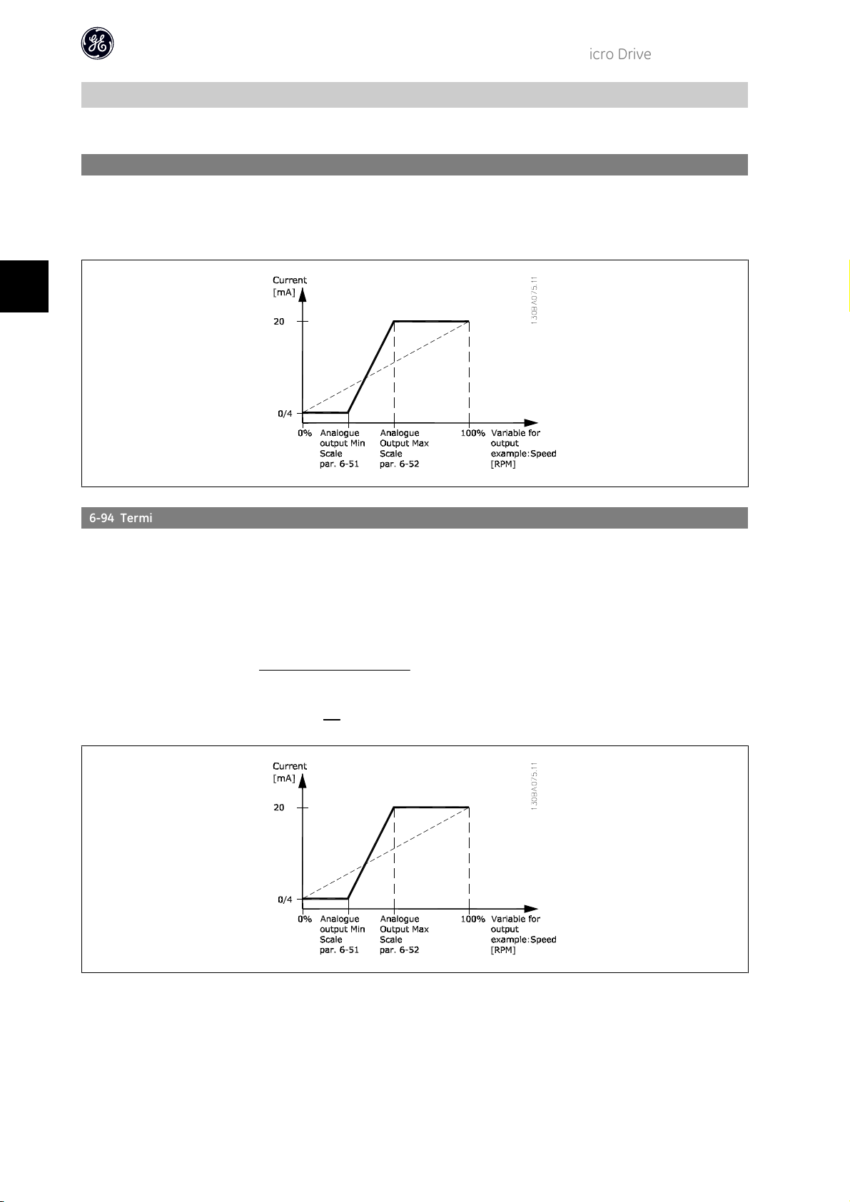
6-94 Terminal 42 Output Max. Scale
Range: Function:
100.00%* [0.00 - 200.00%]
Scale maximum output of selected analog signal at terminal 42. Set value to maximum value of current signal output.
Scale output to give a current lower than 20 mA at full scale; or 20 mA at an output below 100% of maximum signal
value.
If 20 mA is the desired output current at a value between 0 - 100% of the full-scale output, programme percentage
value in the parameter, i.e. 50% = 20 mA. If a current between 4 and 20 mA is desired at maximum output (100%),
calculate percentage value as follows:
desired maximum current
i.e.
10
mA
20
mA
20
=
× 100 = 200 %
10
×100%
40
Page 42

4.8. Parameter Group 7: Controllers
4.8.1. 7-** Controllers
Parameters group for configuring application controls.
4.8.2. 7-2* Process Ctrl. Feedb
Select feedback sources and handling for Process PI Control.
AF-60 LP™ Micro Drive Programming Guide
NB!
Set par. 3-15 to [0] No Function in order to use Analog Input as a feedback signal.
7-20 Process CL Feedback Resources
Option: Function:
Select input to function as feedback signal.
[0]
*
[1] Analog Input 53
[2] Analog Input 60
[8] Pulse Input 33
[11] Local Bus Ref.
No Function
4.8.3. 7-3* Process PI Control
7-30 Process PI Normal/Inverse Control
Option: Function:
[0]
*
[1] Inverse Feedback larger than setpoint result in a speed increase.
7-31 Process PI Anti Windup
Option: Function:
[0] Disable Regulation of a given error will continue even when the output frequency cannot be increased/decreased.
*
[1]
Normal Feedback larger than setpoint result in a speed reduction.
Feedback less than setpoint result in a speed increase.
Feedback less than setpoint result in a speed reduction.
Enable PI-controller ceases from regulating a given error when the output frequency cannot be increased/decreased.
4
7-32 Process PI Start Speed
Range: Function:
0.0 Hz* [0.0 - 200.0 Hz]
Until the set motor speed has been reached the frequency converter operates in Open Loop mode.
7-33 Process PI Proportional Gain
Option: Function:
[0.01]
0.00 - 10.00 Enter the value for the P proportional gain, i.e. the multiplication factor of the error between the set point and the
*
feedback signal.
Note! 0.00 = Off.
7-34 Process PI Integral Time
Range: Function:
9999.00 s* [0.10 - 9999.00 s]
The integrator provides an increasing gain at a constant error between the set point and the feedback signal. The
integral time is the time needed by the integrator to reach the same gain as the proportional gain.
41
Page 43

4
7-38 Process Feed Forward Factor
Range: Function:
0%* [0 - 400%]
The FF factor sends a part of the reference signal around the PI controller which then only affects part of the control
signal.
By activating the FF factor less overshoot and high dynamics are gained when changing the setpoint.
This parameter is always active when par. 1-00 Configuration Mode is set to Process [3].
7-39 On Reference Bandwidth
Range: Function:
5% [0 - 200% ] Enter the value for the On Reference Bandwidth.
The PI control error is the difference between setpoint and feedback and when this is less than the value set in this
parameter the On Reference is active.
AF-60 LP™ Micro Drive Programming Guide
42
Page 44

4.9. Parameter Group 8: Communication
4.9.1. 8-** Communication
Parameter group for configuring communication.
4.9.2. 8-0* General Settings
Use this parameter group for configuring the general settings for communication.
AF-60 LP™ Micro Drive Programming Guide
8-01 Control Site
Option: Function:
[0]
*
[1] Digital Only Use digital input as control.
[2] Control Word Only Use control word only as control.
Digital and Control Word Use both digital input and control word as control.
NB!
The setting in this parameter overrules settings in par. 8-50 to 8-56.
8-02 Control Word Source
Option: Function:
[0] None Function is inactive
[1]
*
Drive RS485 Monitoring control word source is done via serial communication port RS485.
8-03 Control Word Timeout Time
Range: Function:
1.0 s* [0.1 - 6500 s]
Enter time to pass before control word timeout function (par. 8-04) must be carried out.
8-04 Control Word Timeout Function
Option: Function:
Select the action to be taken in case of a timeout.
*
[0]
[1] Freeze Output Freeze output until communication resumes.
[2] Stop Stop with auto restart when communication resumes.
[3] Jogging Run motor at jog frequency until communication resumes.
[4] Max. Speed Run motor at max. frequency until communication resumes.
[5] Stop and Trip Stop motor, then reset frequency converter in order to restart either via Keypad or digital input.
Off No function.
4
8-06 Reset Control Word Timeout
Option: Function:
Resetting the control word timeout will remove any timeout function.
*
[0]
[1] Do Reset Control word timeout is reset, and parameter goes into No Function state.
No Function Control word timeout is not reset.
4.9.3. 8-3* GE Drive Port Settings
Parameters for configuring the GE Drive Port.
43
Page 45

4
4.9.4. 8-30 Protocol
8-30 Protocol
Option: Function:
Select the protocol to be used. Note that changing protocol will not be effective until after powering off the frequency
converter.
[0]
*
[2] Modbus RTU
8-31 Address
Range: Function:
*
[1 - 126]
1
8-32 Drive Port Baud Rate
Option: Function:
GE Drive Protocol
Select the address for the bus.
Drive-bus range is 1-126.
Modbus range is 1-247.
Select baud rate for Drive Port.
NB!
Changing baud rate will be effective after responding to any ongoing bus-requests.
AF-60 LP™ Micro Drive Programming Guide
[0] 2400 Baud
[1] 4800 Baud
*
[2]
[3] 19200 Baud
[4] 38400 Baud
9600 Baud
8-33 Drive Port Parity
Option: Function:
This parameter only affects Modbus as Drive bus always has even parity.
*
[0]
[1] Odd parity
[2] No Parity (1 stopbit) Select this for Modbus RTU
[3] No Parity (2 stopbit)
Even Parity (1 stopbit)
8-35 Minimum Response Delay
Range: Function:
0.010 s* [0.001 - 0.500 s]
Specify minimum delay time between receiving a request and transmitting a response.
8-36 Max Response Delay
Range: Function:
5.000 s* [0.010 - 10.00 s]
Specify maximum permissible delay time between transmitting a request and receiving a response. Exceeding this time
delay causes control word timeout.
4.9.5. 8-5* Digital/Bus
Parameters for configuring control word Digital/Bus merging.
NB!
Parameters are only active when par. 8-01, Control SIte, is set to Digital and control word [0].
44
Page 46

AF-60 LP™ Micro Drive Programming Guide
8-50 Coasting Select
Option: Function:
Select control of coasting function via digital input and/or bus.
[0] Digital Input Activation via a digital input.
[1] Bus Activation via serial communication port.
[2] LogicAnd Activation via serial communication port and a digital input.
*
[3]
8-51 Quick Stop Select
Option: Function:
[0] Digital Input Activation via a digital input.
[1] Bus Activation via serial communication port.
[2] LogicAnd Activation via serial communication port and a digital input.
*
[3]
8-52 DC Brake Select
Option: Function:
[0] Digital Input Activation via a digital input.
[1] Bus Activation via serial communication port.
[2] LogicAnd Activation via serial communication port and a digital input.
*
[3]
LogicOr Activation via serial communication port or a digital input.
Select control of quick stop function via digital input and/or bus.
LogicOr Activation via serial communication port or a digital input.
Select control of DC brake via digital input and/or bus.
LogicOr Activation via serial communication port or a digital input.
4
8-53 Start Select
Option: Function:
Select control of start function via digital input and/or bus.
[0] Digital Input Activation via a digital input.
[1] Bus Activation via serial communication port.
[2] LogicAnd Activation via serial communication port and a digital input.
*
[3]
LogicOr Activation via serial communication port or a digital input.
8-54 Reversing Select
Option: Function:
Select control of reversing function via digital input and/or bus.
[0] Digital Input Activation via a digital input.
[1] Bus Activation via serial communication port.
[2] LogicAnd Activation via serial communication port and a digital input.
*
[3]
LogicOr Activation via serial communication port or a digital input.
8-55 Set-up Select
Option: Function:
Select control of set-up selection via digital input and/or bus.
[0] Digital Input Activation via a digital input.
[1] Bus Activation via serial communication port.
[2] LogicAnd Activation via serial communication port and a digital input.
*
[3]
LogicOr Activation via serial communication port or a digital input.
45
Page 47

8-56 Preset Reference Select
Option: Function:
Select control of Preset Reference selection via digital input and/or bus.
[0] Digital Input Activation via a digital input.
[1] Bus Activation via serial communication port.
[2] LogicAnd Activation via serial communication port and a digital input.
*
[3]
LogicOr Activation via serial communication port or a digital input.
4.9.6. 8-9* Bus Feedback
AF-60 LP™ Micro Drive Programming Guide
4
Parameter for configuring bus feedback.
8-94 Bus Feedback 1
Range: Function:
0* [0x8000 - 0x7FFF]
Bus feedback is delivered via Drive or Modbus by writing the feedback value into this parameter.
46
Page 48
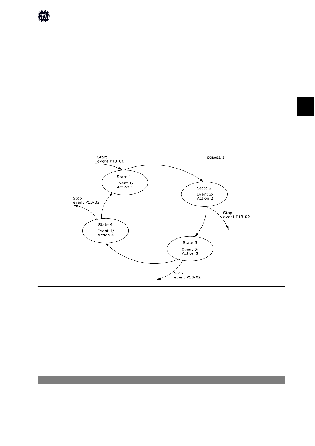
AF-60 LP™ Micro Drive Programming Guide
4.10. Parameter Group 13: Logic Controller
4.10.1. 13-** Programming Features
Logic Controlleris a sequence of user defined actions (par. 13-52 [X]) executed by the Logic Controller when the associated user defined event (par. 13-51 [X]) is
set to True.
Events and actions are linked in pairs, meaning that when an event is true, the linked action is carried out. After this the next event is evaluated and its belonging
action carried out and so on. Only one event is evaluated at the time.
If an event is evaluated as False, the Logic Controller takes no action during the scan interval and no other events are evaluated.
It is possible to programme from 1 to 20 events and actions.
When the last event/action has been executed, the sequence starts again from event/action [0].
The drawing shows an example with three events/actions:
4
Starting and stopping the Logic Controller:
Start the Logic Controller by selecting On [1] in par. 13-00. The Logic Controller starts evaluating Event 0, and if this is evaluated as TRUE, the Logic Controller
continues its cycle.
The Logic Controller stops when the Stop Event, par. 13-02, is TRUE. The Logic Controller can also be stopped by selecting Off [0] in par. 13-00.
To reset all Logic Controller parameters select Reset Logic Controller [1] in par. 13-03 and start programming from scratch.
4.10.2. 13-0* Logic Controller Settings
Use Logic Controller settings to activate, deactive and reset the Logic Controller.
13-00 Logic Controller Mode
Option: Function:
[0]
*
Off Function is disabled.
47
Page 49

4
AF-60 LP™ Micro Drive Programming Guide
[1] On Logic Controller is active.
13-01 Start Event
Option: Function:
Select input to activate Logic Controller.
[0] False Enters False in logic rule.
[1] True Enters True in logic rule.
[2] Running See par. 5-4* [5] for description.
[3] InRange See par. 5-4* [7] for description.
[4] OnReference See par. 5-4* [8] for description.
[7] Out of Current Range See par. 5-4* [12] for description.
[8] BelowILow See par. 5-4* [13] for description.
[9] AboveIHigh See par. 5-4* [14] for description.
[16] ThermalWarning See par. 5-4* [21] for description.
[17] MainsOutOfRange Mains voltage is outside the specified voltage range.
[18] Reversing See par. 5-4* [25] for description.
[19] Warning A warning is active.
[20] Alarm_Trip A trip alarm is active.
[21] Alarm_TripLock A trip lock alarm is active.
[22] Comparator 0 Use result of comparator 0 in logic rule.
[23] Comparator 1 Use result of comparator 1 in logic rule.
[24] Comparator 2 Use result of comparator 2 in logic rule.
[25] Comparator 3 Use result of comparator 3 in logic rule.
[26] LogicRule 0 Use result of logic rule 0 in logic rule.
[27] LogicRule 1 Use result of logic rule 1 in logic rule.
[28] LogicRule 2 Use result of logic rule 2 in logic rule.
[29] LogicRule 3 Use result of logic rule 3 in logic rule.
[33] DigitalInput_18 Use value of DI 18 in logic rule.
[34] DigitalInput_19 Use value of DI 19 in logic rule.
[35] DigitalInput_27 Use value of DI 27 in logic rule.
[36] DigitalInput_29 Use value of DI 29 in logic rule.
[38] DigitalInput_33
*
[39]
[40] DriveStopped This event is True, if frequency converter is stopped or coasted by any means (digital input or other).
StartCommand This event is True, if frequency converter is started by any means (digital input or other).
13-02 Stop Event
Option: Function:
Select input to activate Logic Controller.
[0] False Enters False in logic rule.
[1] True Enters True in logic rule.
[2] Running See par. 5-4* [5] for description.
[3] InRange See par. 5-4* [7] for description.
[4] OnReference See par. 5-4* [8] for description.
[7] Out of Current Range See par. 5-4* [12] for description.
[8] BelowILow See par. 5-4* [13] for description.
[9] AboveIHigh See par. 5-4* [14] for description.
[16] ThermalWarning See par. 5-4* [21] for description.
[17] MainsOutOfRange Mains voltage is outside the specified voltage range.
48
Page 50

AF-60 LP™ Micro Drive Programming Guide
[18] Reversing See par. 5-4* [25] for description.
[19] Warning A warning is active.
[20] Alarm_Trip A trip alarm is active.
[21] Alarm_TripLock A trip lock alarm is active.
[22] Comparator 0 Use result of comparator 0 in logic rule.
[23] Comparator 1 Use result of comparator 1 in logic rule.
[24] Comparator 2 Use result of comparator 2 in logic rule.
[25] Comparator 3 Use result of comparator 3 in logic rule.
[26] LogicRule 0 Use result of logic rule 0 in logic rule.
[27] LogicRule 1 Use result of logic rule 1 in logic rule.
[28] LogicRule 2 Use result of logic rule 2 in logic rule.
[29] LogicRule 3 Use result of logic rule 3 in logic rule.
[30] LC Timeout0 Use result of timer 0 in logic rule.
[31] LC Timeout1 Use result of timer 1 in logic rule.
[32] LC Timeout2 Use result of timer 2 in logic rule.
[33] DigitalInput_18 Use value of DI 18 in logic rule.
[34] DigitalInput_19 Use value of DI 19 in logic rule.
[35] DigitalInput_27 Use value of DI 27 in logic rule.
[36] DigitalInput_29 Use value of DI 29 in logic rule.
[38] DigitalInput_33
[39] StartCommand This event is True, if frequency converter is started by any means (digital input or other).
[40]
*
DriveStopped This event is True, if frequency converter is stopped or coasted by any means (digital input or other).
4
13-03 Reset Logic Controller
Option: Function:
[0]
*
[1] Reset Logic Controller Reset all group 13 parameters to default settings.
Do Not Reset Retains all settings programmed in parameter group 13.
4.10.3. 13-1* Comparators
Comparators are used for comparing continuous variables (i.e. output frequency, output current, analog input etc.) to fixed preset values. In addition, there are
digital values that will be compared to fixed time values. See explanation in par. 13-10. Comparators are evaluated once in each scan interval. Use the result
(TRUE or FALSE) directly. All parameters in this parameter group are array parameters with index 0 to 5. Select index 0 to programme Comparator 0, select index
1 to programme Comparator 1, and so on.
13-10 Comparator Operand
Array [4]
Select variable to be monitored by comparator.
*
[0]
[1] Reference Resulting remote reference (not local) as a percentage.
[2] Feedback Feedback in [Hz].
[3] MotorSpeed Motor speed in Hz.
[4] MotorCurrent Motor current in [A].
[6] MotorPower Motor power in either [kW] or [hp].
[7] MotorVoltage Motor voltage in [V].
[8] DCLinkVoltage DC-link voltage in [V].
[12] AnalogInput53 Expressed as a percentage.
[13] AnalogInput60 Expressed as a percentage.
[18] PulseInput33 Expressed as a percentage.
Disabled Comparator is disabled.
49
Page 51

4
AF-60 LP™ Micro Drive Programming Guide
[20] AlarmNumber Shows number of the alarm.
[30] CounterA Number of counts.
[31] CounterB Number of counts.
13-11 Comparator Operator
Array [4]
Select operator to be used in comparison.
[0] Less Than < Result of evaluation is True if variable selected in par. 13-10 is smaller than fixed value in par. 13-12. Result is False if
variable selected in par. 13-10 is greater than fixed value in par. 13-12.
*
[1]
[2] Greater Than > Inverse logic of option [0].
Approximately equals ป
13-12 Comparator Value
Array [4]
0.0* [-9999 - 9999]
4.10.4. 13-2* Timers
Use the timer results to define an event (par. 13-51) or as boolean input in a logic rule (par. 13-40, 13-42 or 13-44).
When timer value has elapsed timer changes state from False to True.
Result of evaluation is True if variable selected in par. 13-10 is approximately equal to fixed value in par. 13-12.
Enter “trigger level” for variable monitored by this comparator.
13-20 Logic Controller Controller Timer
Array [3]
0.0 s* [0.0 - 3600 s]
Enter value to define duration of the False output from programmed timer. A timer is only False if it is started by an
action and until the given timer value has elapsed.
4.10.5. 13-4* Logic Rules
Combine up to three boolean inputs (TRUE / FALSE inputs) from timers, comparators, digital inputs, status bits and events using the logical operators AND, OR,
and NOT. Select boolean inputs for the calculation in par. 13-40, 13-42, and 13-44. Define the operators used to logically combine the selected inputs in par. 13-41
and 13-43.
Priority of calculation
The results of par. 13-40, 13-41, and 13-42 are calculated first. The outcome (TRUE / FALSE) of this calculation is combined with the settings of par. 13-43 and
13-44, yielding the final result (TRUE / FALSE) of the logic rule.
13-40 Logic Rule Boolean 1
Array [4]
Select first boolean input for selected logic rule.
[0]
*
[1] True Enters True in logic rule.
[2] Running See par. 5-4* [5] for description.
[3] InRange See par. 5-4* [7] for description.
[4] OnReference See par. 5-4* [8] for description.
[7] Out of Current Range See par. 5-4* [12] for description.
[8] BelowILow See par. 5-4* [13] for description.
[9] AboveIHigh See par. 5-4* [14] for description.
[16] ThermalWarning See par. 5-4* [21] for description.
[17] MainsOutOfRange Mains voltage is outside the specified voltage range.
[18] Reversing See par. 5-4* [25] for description.
False Enters False in logic rule.
50
Page 52

AF-60 LP™ Micro Drive Programming Guide
[19] Warning A warning is active.
[20] Alarm_Trip A trip alarm is active.
[21] Alarm_TripLock A trip lock alarm is active.
[22] Comparator 0 Use result of comparator 0 in logic rule.
[23] Comparator 1 Use result of comparator 1 in logic rule.
[24] Comparator 2 Use result of comparator 2 in logic rule.
[25] Comparator 3 Use result of comparator 3 in logic rule.
[26] LogicRule 0 Use result of logic rule 0 in logic rule.
[27] LogicRule 1 Use result of logic rule 1 in logic rule.
[28] LogicRule 2 Use result of logic rule 2 in logic rule.
[29] LogicRule 3 Use result of logic rule 3 in logic rule.
[30] LC Timeout0 Use result of timer 0 in logic rule.
[31] LC Timeout1 Use result of timer 1 in logic rule.
[32] LC Timeout2 Use result of timer 2 in logic rule.
[33] DigitalInput_18 Use value of DI 18 in logic rule.
[34] DigitalInput_19 Use value of DI 19 in logic rule.
[35] DigitalInput_27 Use value of DI 27 in logic rule.
[36] DigitalInput_29 Use value of DI 29 in logic rule.
[38] DigitalInput_33
[39] StartCommand This event is True, if frequency converter is started by any means (digital input or other).
[40] DriveStopped This event is True, if frequency converter is stopped or coasted by any means (digital input or other).
4
13-41 Logic Rule Operator 1
Array [4]
Select first logical operator to use on boolean inputs from par. 13-40 and 13-42.
*
[0]
[1] And Evaluates expression [13-40] AND [13-42].
[2] Or Evaluates expression [13-40] OR [13-42].
[3] And not Evaluates expression [13-40] AND NOT [13-42].
[4] Or not Evaluates expression [13-40] OR NOT [13-42].
[5] Not and Evaluates expression NOT [13-40] and [13-42].
[6] Not or Evaluates expression NOT [13-40] OR [13-42].
[7] Not and not Evaluates expression NOT [13-40] AND NOT [13-42].
[8] Not or not Evaluates expression NOT [13-40] OR NOT [13-42].
Disabled Ignores parameters 13-42, 13-43 and 13-44.
13-42 Logic Rule Boolean 2
Array [4]
Select second boolean input for selected logic rule.
See par. 13-40 for choices and descriptions.
13-43 Logic Rule Operator 2
Array [4]
Select second logical operator to use on boolean inputs calculated in par. 13-40, 13-41, and 13-42 and the boolean
input from par. 13-42.
[0]
*
[1] And Evaluates expression [13-40/13-42] AND [13-44].
[2] Or Evaluates expression [13-40/13-42] OR [13-44].
[3] And not Evaluates expression [13-40/13-42] AND NOT [13-44].
[4] Or not Evaluates expression [13-40/13-42] OR NOT [13-44].
Disabled Ignores parameter 13-44.
51
Page 53

4
AF-60 LP™ Micro Drive Programming Guide
[5] Not and Evaluates expression NOT [13-40/13-42] and [13-44].
[6] Not or Evaluates expression NOT [13-40/13-42] OR [13-44].
[7] Not and not Evaluates expression NOT [13-40/13-42] AND NOT [13-44].
[8] Not or not Evaluates expression NOT [13-40/13-42] OR NOT [13-44].
13-44 Logic Rule Boolean 3
Array [4]
Select third boolean input for selected logic rule.
See par. 13-40 for choices and descriptions.
4.10.6. 13-5* States
Parameters for programming the Logic Controller.
13-51 Logic Controller Event
Array [20]
Select boolean input to define Logic Controller Event.
See par. 13-40 for choices and descriptions.
13-52 LC Controller Action
Array [20]
Select action corresponding to LC event. Actions are executed when corresponding event (par. 13-51) is evaluated as
True.
[0]
*
[1] No Action No action is taken.
[2] Select Set-up1 Changes active set-up to Set-up 1.
[3] Select Set-up2 Changes active set-up to Set-up 2.
[10] SelectPresetRef0 Selects preset reference 0
[11] SelectPresetRef1 Selects preset reference 1
[12] SelectPresetRef2 Selects preset reference 2
[13] SelectPresetRef3 Selects preset reference 3
[14] SelectPresetRef4 Selects preset reference 4
[15] SelectPresetRef5 Selects preset reference 5
[16] SelectPresetRef6 Selects preset reference 6
[17] SelectPresetRef7 Selects preset reference 7
[18] SelectRamp1 Selects ramp 1
[19] SelectRamp2 Selects ramp 2
[22] Run Issues start command to frequency converter.
[23] RunReverse Issues start reverse command to frequency converter.
[24] Stop Issues stop command to frequency converter.
[25] Qstop Issues quick stop command to frequency converter.
[26] DCstop Issues DC stop command to frequency converter.
[27] Coast Frequency converter coasts immediately. All stop commands including coast command stop the Logic Controller.
[28] Freeze Output Freezes output frequency.
[29] StartTimer0 Starts timer 0.
[30] StartTimer1 Starts timer 1
[31] StartTimer2 Starts timer 2
[32] SetDO42Low Set Digital output 42 low.
[33] SetRelayLow Set Relay low.
[38] SetDO42High Set Digital output 42 high.
Disabled Function is disabled.
52
Page 54

[39] SetRelayHigh Set Relay high.
[60] ResetCounterA Resets counter A to 0.
[61] ResetCounterB Resets counter B to 0.
AF-60 LP™ Micro Drive Programming Guide
4
53
Page 55

4.11. Parameter Group 14: Special Functions
4.11.1. 14-** Special Functions
Parameter group for configuring special frequency converter functions.
4.11.2. Carrier Frequency 14-0*
Parameters for configuring the carrier frequency.
AF-60 LP™ Micro Drive Programming Guide
4
14-01 Motor Noise (Carrier Frequency)
Option: Function:
Select the carrier frequency in order to minimize e.g. acoustic noise and power loss or maximizing efficiency.
[0] 2 KHz
*
[1]
[2] 8 KHz
[4] 16 KHz
4 KHz
14-03 Overmodulation
Option: Function:
This feature allows more accurate speed control near and over nominal speed (50/60 Hz). Another advantage with
overmodulation is the ability of staying at a constant speed even though mains is dropping.
[0] Off Disables the overmodulation function to avoid torque ripple on the motor shaft.
*
[1]
On Connects the overmodulation function to obtain an output voltage up to 15% greater than mains voltage.
4.11.3. 14-1* Mains Monitoring
This parameter group supplies functions for handling imbalance on mains.
14-12 Functions at Mains Imbalance
Option: Function:
Operation under severe mains imbalance conditions reduces drive lift time.
Select function to take place when severe mains imbalance is detected.
[0]
*
[1] Warning Frequency converter issues a warning.
[2] Disabled No action taken.
Trip Frequency converter trips.
4.11.4. Trip Reset, 14-2*
Parameters for configuring auto reset handling, special trip handling and control card self test or initialisation.
14-20 Reset Mode
Option: Function:
Select reset function after tripping. Once reset, frequency converter can be restarted.
[0]
*
[1] AutoReset 1 Performs one automatic reset after tripping.
[2] AutoReset 2 Performs two automatic resets after tripping.
[3] AutoReset 3 Performs three automatic resets after tripping.
[4] AutoReset 4 Performs four automatic resets after tripping.
[5] AutoReset 5 Performs five automatic resets after tripping.
Manual Reset Perform reset via [reset]-button or digital inputs.
54
Page 56

AF-60 LP™ Micro Drive Programming Guide
[6] AutoReset 6 Performs six automatic resets after tripping.
[7] AutoReset 7 Performs seven automatic resets after tripping.
[8] AutoReset 8 Performs eight automatic resets after tripping.
[9] AutoReset 9 Performs nine automatic resets after tripping.
[10] AutoReset 10 Performs ten automatic resets after tripping.
[11] AutoReset 15 Performs fifteen automatic resets after tripping.
[12] AutoReset 20 Performs twenty automatic resets after tripping.
[13] Infinite auto reset Performs an infinite number of automatic resets after tripping.
Motor may start without warning.
14-21 Automatic Restart Time
Range: Function:
10 s* [0 - 600 s]
Enter time interval from trip to start of automatic reset function. This parameter is active when par. 14-20, Reset
Mode, is set to Automatic Reset [1] - [13].
14-22 Operation Mode
Option: Function:
Use this parameter for specifying normal operation or to initialize all parameters, except par. 15-03, 15-04 and 15-05.
*
[0]
[2] Restore Factory Settings Resets all parameters to default settings, except for 15-03, 15-04 and 15-05. Frequency converter resets during next
Normal Operation Frequency converter runs normal operation.
power-up.
Par. 14-22 also reverts to default setting Normal Operation [0].
4.11.5. 14-4* Energy Savings
These parameters are for adjusting the energy savings level in both Variable Torque (VT) and Energy savings modes.
14-41 Energy savingsMinimum Magnetization
Range: Function:
66%* [40 - 75%]
Enter the minimum allowable magnetization for energy savings. Selecting a low value reduces energy loss in the motor,
but may also reduce resistance to sudden load changes.
4
55
Page 57

AF-60 LP™ Micro Drive Programming Guide
4.12. Parameter Group 15: Drive Information
4.12.1. 15-** Drive Information
Parameter group containing information on operating data, hardware configuration, software version, etc.
4.12.2. 15-0* Operating Data
Parameter group containing operating data e.g. Operating Hours, kWh counters, Power Ups, etc.
4
4.12.3. 15-00 Operating Time
15-00 Operating Time
Range: Function:
0 days* [0 - 65535 days]
15-01 Running Hours
Range: Function:
0* [0 - 2147483647]
15-02 kWh Counter
Range: Function:
0 [0 - 65535] View power consumption in kWh as a mean value over one hour.
15-03 Power Ups
Range: Function:
0 [0 - 2147483647] View number of times frequency converter has been powered up.
15-04 Over Temps
Range: Function:
0 [0 - 65535] View number of times frequency converter has tripped due to over temperature.
View running hours of frequency converter.
The value is saved at power off and cannot be reset.
View running hours of motor.
The value is saved at power off and can be reset in par. 15-07, Reset Running Hours Counter.
Reset counter in par. 15-06, Reset kWh Counter.
Counter cannot be reset.
Counter cannot be reset.
15-05 Over Volts
Range: Function:
0* [0 - 65535]
View number of times frequency converter has tripped due to over voltage.
Counter cannot be reset.
15-06 Reset kWh Counter
Option: Function:
[0]
*
[1] Reset Counter Counter is reset.
Do Not Reset Counter is not reset.
15-07 Reset Running Hours Counter
Option: Function:
[0]
*
[1] Reset Counter Counter is reset.
Do Not Reset Counter is not reset.
56
Page 58

AF-60 LP™ Micro Drive Programming Guide
4.12.4. 15-3* Fault Log
This parameter group contains a fault log showing reasons for the ten latest trips.
15-30 Fault Log: Error Code
Range: Function:
0 [0 - 255] View error code and look it up in GE AF-60 LP Micro Operating Instructions.
4.12.5. Drive Identification, 15-4*
Parameters containing read only information about the hardware and software configuration of the frequency converter.
15-40 Drive Type
Option: Function:
View Drive type.
15-41 Power Section
Option: Function:
View power section of frequency converter.
15-42 Voltage
Option: Function:
View voltage of frequency converter.
4
15-43 Software Version
Option: Function:
View software version of frequency converter.
15-46 Frequency Converter Ordering No
Option: Function:
View ordering number for re-ordering frequency converter in its original configuration.
15-48 Keypad ID No
Option: Function:
View Keypad ID number.
15-51 Frequency Converter Serial Number
Option: Function:
View frequency converter serial number.
57
Page 59

AF-60 LP™ Micro Drive Programming Guide
4.13. Parameter Group 16: Data Readouts
4.13.1. 16-** Data Readouts
Parameter group for data read-outs, e.g. actual references, voltages, control, alarm, warning and status words.
4.13.2. 16-0* General Status
Parameters for reading the general status, e.g. the calculated reference, the active control word, status.
4
16-00 Control Word
Range: Function:
0* [0 - 65535]
View latest valid control word sent to frequency converter via serial communication port.
16-01 Reference [Unit]
Range: Function:
0.000* [-4999.000 - 4999.000]
View total remote reference. Total reference is sum of pulse, analog, preset, Keypad potentiometer, local bus and freeze
reference.
16-02 Reference %
Range: Function:
0.0* [-200.0 - 200.0%]
View total remote reference in percent. Total reference is sum of pulse , analog, preset, Keypad potentiometer, local bus
and freeze reference.
16-03 Status Word
Range: Function:
0* [0 - 65535]
View status word sent to frequency converter via serial communication port.
16-05 Main Actual Value %
Range: Function:
0.00* [-100.00 - 100.00%]
View two-byte word sent with status word to bus Master reporting main actual value.
4.13.3. 16-09 Custom Readout
16-09 Custom Readout
Range: Function:
0.00* [0.00 - 9999.00%]
Customized readout based on the settings of par. 0-31, par. 0-32 and par. 4-14
4.13.4. 16-1* Motor Status
Parameters for reading the motor status values.
16-10 Power [kW]
Range: Function:
0 kW* [0 - 99 kW]
16-11 Power [hp]
Range: Function:
0 hp [0 - 99 hp ] View output power in hp.
View output power in kW.
58
Page 60

16-12 Motor Voltage
Range: Function:
0.0* [0.0 - 999.9 V]
View motor phase voltage.
16-13 Frequency
Range: Function:
0.0 Hz* [0.0 - 400.0 Hz]
View output frequency in Hz.
16-14 Motor Current
Range: Function:
0.00 A* [0.00 - 655 A]
View motor phase current.
16-15 Frequency [%]
Range: Function:
0.00* [-100.00 - 100.00%]
View a two-byte word reporting actual motor frequency as a percentage of par. X-XX
16-18 Motor Thermal
Range: Function:
0%* [0 - 100%]
View calculated thermal motor load as percentage of estimated thermal motor load.
AF-60 LP™ Micro Drive Programming Guide
4
4.13.5. 16-3* Drive Status
Parameters for reporting the status of the frequency converter.
16-30 DC Link Voltage
Range: Function:
0 V* [0 - 10000 V]
16-34 Heat Sink Temp.
Range: Function:
0* [0 - 255rC]
16-35 Drive Thermal
Range: Function:
0%* [0 - 100%]
16-36 Drive Nom. Current
Range: Function:
0.00 A* [0.01 - 655A]
16-37 Drive Max. Current
Range: Function:
0.00 A* [0.1 - 655A]
View DC-link voltage.
View heat sink temperature of frequency converter.
View calculated thermal load on frequency converter in relation to estimated thermal load on frequency converter.
View continuous nominal drive current.
View intermittent maximum drive current (150%).
16-38 Logic Controller State
Range: Function:
0* [0 - 255]
View number of active Logic state.
4.13.6. 16-5* Ref. & Feedb.
Parameters for reporting the reference and feedback input.
59
Page 61

4
16-50 External Reference
Range: Function:
0.0%* [-200.0 - 200.0%]
View sum of all external references in percent.
16-51 Pulse Reference
Range: Function:
0.0 %* [-200.0 - 200.0%]
View actual pulse input converted to a reference in percent.
16-52 Feedback
Range: Function:
0.000* [-4999.000 - 4999.000]
View analog or pulse feedback in Hz.
4.13.7. 16-6* Inputs and Outputs
Parameters for reporting the digital and analog IO ports.
16-60 Digital Input 18, 19, 27, 33
Range: Function:
0* [0 - 1111]
View signal states from active digital inputs.
AF-60 LP™ Micro Drive Programming Guide
16-61 Digital Input 29
Range: Function:
0* [0 - 1]
View signal state on digital input 29.
16-62 Analog Input 53 (volt)
Range: Function:
0.00* [0.00 - 10.00 V]
View input voltage on analog input terminal.
16-63 Analog Input 53 (current)
Range: Function:
0.00* [0.00 - 20.00 mA]
View input current on analog input terminal.
16-64 Analog Input 60
Range: Function:
0.00* [0.00 - 20.00 mA]
View actual value at input 60 either as reference or protection value.
16-65 Analog Output 42 [mA]
Range: Function:
0.00 mA* [0.00 - 20.00 mA]
View output current on analog output 42.
16-68 Pulse Input
Range: Function:
20 Hz* [20 - 5000 Hz]
View input frequency on pulse input terminal.
16-71 Relay Output [bin]
Range: Function:
0* [0 - 1]
View relay setting.
16-72 Counter A
Range: Function:
0* [-32768 - 32767]
View present value of Counter A.
60
Page 62

16-73 Counter B
Range: Function:
0* [-32768 - 32767]
View present value of Counter B.
4.13.8. 16-8* GE Drive Port
Parameter for viewing references from GE Drive Port.
16-86 GE Drive Port REF 1
Range: Function:
0* [0x8000 - 0x7FFF]
View currently received reference from GE Drive Port.
4.13.9. 16-9* Diagnosis Read-Out
Parameters displaying alarm, warning and extended status words.
16-90 Alarm Word
Range: Function:
0* [0 - 0xFFFFFFFF]
Via alarm word sent via serial communication port in hex code.
AF-60 LP™ Micro Drive Programming Guide
4
16-92 Warning Word
Range: Function:
0* [0 - 0xFFFFFFFF]
View warning word sent via serial communication port in hex code.
16-94 Ext. Status Word
Range: Function:
0* [0 - 0xFFFFFFFF]
View extended warning word sent via serial communication port in hex code.
61
Page 63

5
AF-60 LP™ Micro Drive Programming Guide
62
Page 64

5. Parameter Lists
[1] Analog input 53
[6] Digital input 29
2-** Brakes
2-0* DC-Brake
2-00 DC Hold Current
0 - 150 % * 50 %
2-01 DC Brake Current
0 - 150 % * 50 %
2-02 DC Braking Time
0.0 - 60.0 s * 10.0 s
2-04 DC Brake Cut In Speed
0.0 - 400.0 Hz * 0.0 Hz
2-1* Brake Energy Funct.
2-10 Brake Function
*[0] Off
[1] Resistor brake
[2] AC brake
2-11 Brake Resistor (ohm)
5 - 5000 * 5
2-16 AC Brake, Max current
0 - 150 % * 100 %
2-17 Over-voltage Control
*[0] Disabled
[1] Enabled (not at stop)
[2] Enabled
2-2* Mechanical Brake
2-20 Release Brake Current
0.00 - 100.0 A * 0.00 A
2-22 Activate Brake Speed [Hz]
AF-60 LP™ Micro Drive Programming Guide
0.0 - 400.0 Hz * 0.0 Hz
3-** Reference / Ramps
3-0* Reference Limits
3-00 Reference Range
*[0] Min - Max
[1] -Max - +Max
3-02 Minimum Reference
-4999 - 4999 * 0.000
3-03 Maximum Reference
-4999 - 4999 * 50.00
3-1* References
3-10 Preset Reference
-100.0 - 100.0 % * 0.00 %
3-11 Jog Speed [Hz]
0.0 - 400.0 Hz * 5.0 Hz
3-12 Catch up/slow Down Value
0.00 - 100.0 % * 0.00 %
5
Parameter Overwiev
1-33 Stator Leakage Reactance (X1)
[Ohm] * Dep. on motor data
1-35 Main Reactance (Xh)
1-0* General Settings
1-00 Configuration Mode
*[0] Speed open loop
[Ohm] * Dep. on motor data
1-5* Load Indep. Setting
[3] Process
1-01 Motor Control Principle
1-50 Motor Magnetisation at 0 Speed
0 - 300 % * 100 %
1-52 Min Speed Norm. Magnet. [Hz]
[0] U/f
*[1] Adv.Vector Control
1-03 Torque Characteristics
0.0 - 10.0 Hz * 0.0 Hz
1-55 U/f Characteristic - U
*[0] Constant torque
[2] Energy Saving
0 - 999.9 V
1-56 U/f Characteristic - F
0 - 400 Hz
1-05 Local Mode Configuration
[0] Speed Open Loop
*[2] As config in param. 1-00
1-6* Load Depen. Setting
1-60 Low Speed Load Compensation
0 - 199 % * 100 %
1-61 High Speed Load Compensation
1-2* Motor Data
1-20 Motor Power [kW] [HP]
[1] 0.09 kW/0.12 HP
[2] 0.12 kW/0.16 HP
0 - 199 % * 100 %
1-62 Slip Compensation
-400 - 399 % * 100 %
[3] 0.18 kW/0.25 HP
[4] 0.25 kW/0.33 HP
[5] 0.37 kW/0.50 HP
1-63 Slip Compensation Time Constant
0.05 - 5.00 s * 0.10 s
1-7* Start Adjustments
1-71 Holding Time
0.0 - 10.0 s * 0.0 s
1-72 Start Function
[6] 0.55 kW/0.75 HP
[7] 0.75 kW/1.00 HP
[8] 1.10 kW/1.50 HP
[9] 1.50 kW/2.00 HP
[10] 2.20 kW/3.00 HP
[11] 3.00 kW/4.00 HP
[0] DC hold / delay time
[1] DC brake / delay time
*[2] Coast / delay time
1-73 Start Mode
*[0] Disabled
[1] Enable - Catch Spinning Load
1-8* Stop Adjustments
1-80 Function at Stop
[12] 3.70 kW/5.00 HP
[13] 4.00 kW/5.40 HP
[14] 5.50 kW/7.50 HP
[15] 7.50 kW/10.00 HP
[16] 11.00 kW/15.00 HP
1-22 Motor Voltage
50 - 999 V * 230 - 400 V
1-23 Motor Frequency
*[0] Coast
[1] DC hold
1-82 Min Speed for Funct. at Stop [Hz]
0.0 - 20.0 Hz * 0.0 Hz
20 - 400 Hz * 60 Hz
1-24 Motor Current
0.01 - 26.00 A * Motortype dep.
1-25 Motor Nominal Speed
1-9* Motor Temperature
1-90 Motor Thermal Protection
100 - 9999 rpm * Motortype dep.
1-29 Auto Tune
*[0] No protection
[1] Termistor warning
*[0] Off
[2] Enable Auto Tune
[2] Thermistor trip
[3] Electronic Overload warning
1-3* Adv. Motor Data
1-30 Stator Resistance (Rs)
[4] Electronic Overload trip
1-93 Thermistor Resource
[Ohm] * Dep. on motor data
*[0] None
0-** Operation/Display
0-0* Basic Settings
0-03 Regional Settings
[0] International
*[1] US
0-04 Oper. State at Power-up (Hand)
[0] Resume
*[1] Forced stop, ref = old
[2] Forced stop, ref = 0
0-1* Set-up Handling
0-10 Active Set-up
*[1] Setup 1
[2] Setup 2
[9] Multi Setup
0-11 Edit Set-up
*[1] Setup 1
[2] Setup 2
[9] Active Setup
0-12 Link Setups
[0] Not Linked
*[20] Linked
0-31 Custom Readout Min Scale
0.00 – 9999.00
*0.00
0-32 Custom Readout Max Scale
0.00 – 9999.00
*100.0
0-4* Keypad
0-40 [Hand] Key on Keypad
[0] Disabled
*[1] Enabled
0-41 [Off / Reset] Key on Keypad
[0] Disable All
*[1] Enable All
[2] Enable Reset Only
0-42 [Auto] Key on Keypad
[0] Disabled
*[1] Enabled
0-5* Copy/Save
0-50 Keypad Copy
*[0] No copy
[1] All to Keypad
[2] All from Keypad
[3] Size indep. from Keypad
0-51 Set-up Copy
*[0] No copy
[1] Copy from setup 1
[2] Copy from setup 2
[9] Copy from Factory setup
0-6* Password
0-60 (Main) Menu Password
0 - 999 * 0
1-** Load/Motor
63
Page 65

5
AF-60 LP™ Micro Drive Programming Guide
[25] Reverse
[26] Bus ok
[28] Brake,NoWarn
[29] Brake ready/NoFault
[30] BrakeFault (IGBT)
[32] Mech.brake control
[36] Control word bit 11
[51] Local ref. active
[52] Remote ref. active
[53] No alarm
[54] Start cmd active
[55] Running reverse
[56] Drive in hand mode
[57] Drive in auto mode
[60-63] Comparator 0-3
[70-73] Logic rule 0-3
[81] Logic Controller digital output B
5-5* Pulse Input
5-55 Terminal 33 Low Frequency
20 - 4999 Hz * 20 Hz
5-56 Terminal 33 High Frequency
21 - 5000 Hz * 5000 Hz
5-57 Term. 33 Low Ref./Feedb. Value
-4999 - 4999 * 0.000
5-58 Term. 33 High Ref./Feedb. Value
-4999 - 4999 * 50.000
6-** Analog In/Out
6-0* Analog I/O Mode
6-00 Live Zero Timeout Time
1 - 99 s * 10 s
6-01 Live Zero TimeoutFunction
*[0] Off
[1] Freeze output
[2] Stop
[3] Jogging
[4] Max speed
[5] Stop and trip
6-1* Analog Input 1
6-10 Terminal 53 Low Voltage
0.00 - 9.99 V * 0.07 V
6-11 Terminal 53 High Voltage
0.01 - 10.00 V * 10.00 V
6-12 Terminal 53 Low Current
0.00 - 19.99 mA * 0.14 mA
[16-18] Preset ref bit 0-2
[19] Freeze reference
[20] Freeze output
[21] Speed up
3-80 Jog Accel and Decel Time
0.05 - 3600 s * 3.00 s
3-81 Quick Stop Decel Time
0.05 - 3600 s * 3.00 s
[22] Speed down
[23] Setup select bit 0
[28] Catch up
[29] Slow down
4-** Limits / Warnings
4-1* Motor Limits
4-10 Reverse Lock
[0] Reverse Lock
[34] Ramp bit 0
[60] Counter A (up)
[1] Reverse
*[2] Both
[61] Counter A (down)
4-12 Motor Speed Low Limit [Hz]
[62] Reset counter A
[63] Counter B (up)
0.0 - 400.0 Hz * 0.0 Hz
4-14 Motor Speed High Limit [Hz]
[64] Counter B (down)
[65] ResetCounter B
5-11 Terminal 19 Digital Input
0.1 - 400.0 Hz * 65.0 Hz
4-16 Torque Limit Motor Mode
0 - 400 % * 150 %
See par. 5-10. * [10] Reversing
5-12 Terminal 27 Digital Input
4-17 Torque Limit Generator Mode
0 - 400 % * 100 %
See par. 5-10. * [1] Reset
5-13 Terminal 29 Digital Input
See par. 5-10. * [14] Jog
4-5* Adj. Warnings
4-50 Warning Current Low
0.00 - 26.00 A * 0.00 A
5-15 Terminal 33 Digital Input
4-51 Warning Current High
See par. 5-10. * [16] Preset ref bit 0
[26] Precise Stop Inverse
0.00 - 26.00 A * 26.00 A
4-58 Missing Motor Phase Function
[27] Start, Precise Stop
[32] Pulse Input
[0] Off
*[1] On
5-4* Relays
4-6* Jump Frequencies
5-40 Function Relay
4-61 Jump Frequency From [Hz]
*[0] No opreation
[1] Control ready
0.0 - 400.0 Hz * 0.0 Hz
4-63 Jump FrequencyTo [Hz]
[2] Drive ready
[3] Drive ready, Remote
[4] Enable / No warning
0.0 - 400.0 Hz * 0.0 Hz
5-1* Digital Inputs
5-10 Terminal 18 Digital Input
[5] Drive running
[6] Running / No warning
[7] Run in range / No warning
[8] Run on ref / No warning
[9] Alarm
[0] No function
[1] Reset
[2] Coast inverse
[3] Coast and reset inv.
[4] Quick stop inverse
[10] Alarm or warning
[5] DC-brake inv.
[12] Out of current range
[6] Stop inv
[13] Below current, low
*[8] Start
[14] Above current, high
[21] Thermal warning
[22] Ready, No thermal warning
[23] Remote ready, No thermal warning
[9] Latched start
[10] Reversing
[11] Start reversing
[12] Enable start forward
[24] Ready, Voltage ok
[13] Enable start reverse
[14] Jog
64
3-14 Preset Relative Reference
-100.0 - 100.0 % * 0.00 %
3-15 Reference Resource 1
[0] No function
*[1] Analog Input 53
[2] Analog input 60
[8] Pulse input 33
[11] Local bus ref
[21] Keypad Potentiometer
3-16 Reference Resource 2
[0] No function
[1] Analog Input 53
*[2] Analog input 60
[8] Pulse input 33
[11] Local bus ref
[21] Keypad Potentiometer
3-17 Reference Resource 3
[0] No function
[1] Analog Input 53
[2] Analog input 60
[8] Pulse input 33
*[11] Local bus ref
[21] Keypad Potentiometer
3-18 Relative Scaling Ref. Resource
*[0] No function
[1] Analog Input 53
[2] Analog input 60
[8] Pulse input 33
[11] Local bus ref
[21] Keypad Potentiometer
3-4* Accel/Decel 1
3-40 Accel/Decel 1 Pattern
*[0] Linear
[2] S-Shape
3-41 Accel Time 1
0.05 - 3600 s * 3.00 s
3-42 Decel Time 1
0.05 - 3600 s * 3.00 s
3-5* Accel/Decel 2
3-50 Accel/Decel 2 Pattern
*[0] Linear
[2] S-Shape
3-51 Accel Time 2
0.05 - 3600 s * 3.00 s
3-52 Decel Time 2
0.05 - 3600 s * 3.00 s
3-8* Other Ramps
Page 66

8-9* Bus Jog / Feedback
8-94 Bus feedback 1
0x8000 - 0x7FFF * 0
13-** Controller Logic
13-0* Logic Controller Settings
13-00 Logic Controller Mode
*[0] Off
[1] On
13-01 Start Event
[0] False
AF-60 LP™ Micro Drive Programming Guide
[1] True
[2] Running
[3] InRange
[4] OnReference
[7] OutOfCurrentRange
[8] BelowILow
[9] AboveIHigh
[16] ThermalWarning
[17] MainOutOfRange
[18] Reversing
[19] Warning
[20] Alarm_Trip
[21] Alarm_TripLock
[22-25] Comparator 0-3
[26-29] LogicRule0-3
[33] DigitalInput_18
[34] DigitalInput_19
[35] DigitalInput_27
[36] DigitalInput_29
[38] DigitalInput_33
*[39] StartCommand
[40] DriveStopped
13-02 Stop Event
See par. 13-01 * [40] DriveStopped
13-03 Reset Logic Controller
*[0] Do not reset
[1] Reset Logic Controller
13-1* Comparators
5
[4] Max. Speed
[5] Stop and trip
8-06 Reset Control Word Timeout
*[0] No Function
[1] Do reset
8-3* GE Drive Port Settings
8-30 Protocol
*[0] GE Drive
[2] Modbus RTU
6-93 Terminal 42 Output Min Scale
0.00 - 200.0 % * 0.00 %
6-94 Terminal 42 Output Max Scale
0.00 - 200.0 % * 100.0 %
7-** Controllers
7-2* Process Ctrl. Feedb
7-20 Process CL Feedback 1 Resource
*[0] NoFunction
[1] Analog Input 53
8-31 Address
1 - 247 * 1
8-32 GE Drive Port Baud Rate
[0] 2400 Baud
[2] Analog input 60
[8] PulseInput33
[11] LocalBusRef
7-3* Process PI
[1] 4800 Baud
*[2] 9600 Baud
[3] 19200 Baud
*[4] 38400 Baud
Ctrl. 7-30 Process PI Normal/ Inverse Ctrl
*[0] Normal
[1] Inverse
7-31 Process PI Anti Windup
8-33 GE Drive Port Parity
*[0] Even Parity, 1 Stop Bit
[1] Odd Parity, 1 Stop Bit
[2] No Parity, 1 Stop Bit
[0] Disable
*[1] Enable
7-32 Process PI Start Speed
0.0 - 200.0 Hz * 0.0 Hz
[3] No Parity, 2 Stop Bits
7-33 Process PI Proportional Gain
8-35 Minimum Response Delay
0.001-0.5 * 0.010 s
0.00 - 10.00 * 0.01
7-34 Process PI Integral Time
8-36 Max Response Delay
0.100 - 10.00 s * 5.000 s
0.10 - 9999 s * 9999 s
7-38 Process PI Feed Forward Factor
8-5* Digital/Bus
0 - 400 % * 0 %
8-50 Coasting Select
[0] DigitalInput
[1] Bus
[2] LogicAnd
*[3] LogicOr
8-51 Quick Stop Select
7-39 On Reference Bandwidth
0 - 200 % * 5 %
8-** Comm. and Options
8-0* General Settings
8-01 Control Site
*[0] Digital and ControlWord
See par. 8-50 * [3] LogicOr
8-52 DC Brake Select
[1] Digital only
[2] ControlWord only
See par. 8-50 * [3] LogicOr
8-53 Start Select
8-02 Control Word Source
[0] None
See par. 8-50 * [3] LogicOr
*[1] GE Drive RS485
8-54 Reversing Select
See par. 8-50 * [3] LogicOr
8-03 Control Word Timeout Time
0.1 - 6500 s * 1.0 s
8-55 Set-up Select
See par. 8-50 * [3] LogicOr
8-56 Preset Reference Select
See par. 8-50 * [3] LogicOr
8-04 Control Word Timeout Function
*[0] Off
[1] Freeze Output
[2] Stop
[3] Jogging
6-13 Terminal 53 High Current
0.01 - 20.00 mA * 20.00 mA
6-14 Term. 53 Low Ref./Feedb. Value
-4999 - 4999 * 0.000
6-15 Term. 53 High Ref./Feedb. Value
-4999 - 4999 * 50.000
6-16 Terminal 53 Filter Time Constant
0.01 - 10.00 s * 0.01 s
6-19 Terminal 53 mode
*[0] Voltage mode
[1] Current mode
6-2* Analog Input 2
6-22 Terminal 60 Low Current
0.00 - 19.99 mA * 0.14 mA
6-23 Terminal 60 High Current
0.01 - 20.00 mA * 20.00 mA
6-24 Term. 60 Low Ref./Feedb. Value
-4999 - 4999 * 0.000
6-25 Term. 60 High Ref./Feedb. Value
-4999 - 4999 * 50.00
6-26 Terminal 60 Filter Time Constant
0.01 - 10.00 s * 0.01 s
6-8* Keypad potentiometer
6-81 Keypad potm. Low Reference
-4999 - 4999 * 0.000
6-82 Keypad potm. High Reference
-4999 - 4999 * 50.00
6-9* Analog Output xx
6-90 Terminal 42 Mode
*[0] 0-20 mA
[1] 4-20 mA
[2] Digital Output
6-91 Terminal 42 Analog Output
*[0] No operation
[10] Output Frequency
[11] Reference
[12] Feedback
[13] Motor Current
[16] Power
[20] BusControl
6-92 Terminal 42 Digital Output
See par. 5-40
* [0] No Operation
[80] Logic Controller Digital Output A
65
Page 67

5
AF-60 LP™ Micro Drive Programming Guide
16-1* Motor Status
16-10 Power [kW]
16-11 Power [hp]
16-12 Motor Voltage [V]
16-13 Frequency [Hz]
16-14 Motor Current [A]
16-15 Frequency [%]
16-18 Motor Thermal [%]
16-3* Drive Status
16-30 DC Link Voltage
16-34 Heatsink Temp.
16-35 Inverter Thermal
16-36 Drive Nominal current
16-37 Drive Maximum Current
16-38 Logic Controller State
16-5* Ref. / Feedb.
16-50 External Reference
16-51 Pulse Reference
16-52 Feedback [Unit]
16-6* Inputs / Outputs
16-60 Digital Input 18,19,27,33
0 - 1111
16-61 Digital Input 29
0 - 1
16-62 Analog Input 53 (volt)
16-63 Analog Input 53 (current)
16-64 Analog Input 60
16-65 Analog Output 42 [mA]
16-68 Pulse Input [Hz]
16-71 Relay Output [bin]
16-72 Counter A
16-73 Counter B
16-8* Fieldbus / GE Drive Port
16-86 GE Drive Port REF 1
0x8000 - 0x7FFFF
16-9* Diagnosis Readouts
16-90 Alarm Word
0 - 0XFFFFFFFF
16-92 Warning Word
0 - 0XFFFFFFFF
16-94 Ext. Status Word
0 - 0XFFFFFFFF
14-22 Restore Factory Settings
*[0] Normal Operation
[2] Restore Factory Settings
14-26 Action At Drive Fault
*[0] Trip
[1] Warning
14-4* Energy Savings
14-41 Energy Savings Minimum Magnetisation
40 - 75 % * 66 %
15-** Drive Information
15-0* Operating Data
15-00 Operating Days
15-01 Running Hours
15-02 kWh Counter
15-03 Power Ups
15-04 Over Temps
15-05 Over Volts
15-06 Reset kWh Counter
*[0] Do not reset
[1] Reset counter
15-07 Reset Running Hours Counter
*[0] Do not reset
[1] Reset counter
15-3* Fault Log
15-30 Fault Log: Error Code
15-4* Drive Identification
15-40 GE Drive Type
15-41 Power Section
15-42 Voltage
15-43 Software Version
15-46 Frequency Converter Order. No
15-48 Keypad Id No
15-51 Frequency Converter Serial No
16-** Data Readouts
16-0* General Status
16-00 Control Word
0 - 0XFFFF
16-01 Reference [Unit]
-4999 - 4999
16-02 Reference %
-200.0 - 200.0 %
16-03 Status Word
0 - 0XFFFF
16-05 Main Actual Value [%]
-200.0 - 200.0 %
16-09 Custom Readout
Dep. on par. 0-31, 0-32 and 4-14
[1] NoAction
[2] SelectSetup1
[3] SelectSetup2
[10-17] SelectPresetRef0-7
[18] Select Accel/Decel 1.
[19] Select Accel/Decel 2.
[22] Run
[23] RunReverse
[24] Stop
[25] Qstop
[26] DCstop
[27] Coast
[28] FreezeOutput
[29] StartTimer0
[30] StartTimer1
[31] StartTimer2
[32] Set Digital Output A Low
[33] Set Digital Output B Low
[38] Set Digital Output A High
[39] Set Digital Output B High
[60] ResetCounterA
[61] ResetCounterB
14-** Special Functions
14-0* Carrier Frequency
14-01 Motor Noise
(Carrier Frequency)
[0] 2 kHz
*[1] 4 kHz
[2] 8 kHz
[4] 16 kHz
14-03 Overmodulation
[0] Off
*[1] On
14-1* Mains monitoring
14-12 Function at mains imbalance
*[0] Trip
[1] Warning
[2] Disabled
14-2* Trip Reset
14-20 Reset Mode
*[0] Manual reset
[1-9] AutoReset 1-9
[10] AutoReset 10
[11] AutoReset 15
[12] AutoReset 20
[13] Infinite auto reset
14-21 Automatic Restart Time
0 - 600 s * 10 s
66
13-10 Comparator Operand
*[0] Disabled
[1] Reference
[2] Feedback
[3] MotorSpeed
[4] MotorCurrent
[6] MotorPower
[7] MotorVoltage
[8] DCLinkVoltage
[12] AnalogInput53
[13] AnalogInput60
[18] PulseInput33
[20] AlarmNumber
[30] CounterA
[31] CounterB
13-11 Comparator Operator
[0] Less Than
*[1] Approximately equals
[2] Greater Than
13-12 Comparator Value
-9999 - 9999 * 0.0
13-2* Timers
13-20 LC Controller Timer
0.0 - 3600 s * 0.0 s
13-4* Logic Rules
13-40 Logic Rule Boolean 1
See par. 13-01 * [0] False
[30] - [32] LC Time-out 0-2
13-41 Logic Rule Operator 1
*[0] Disabled
[1] And
[2] Or
[3] And not
[4] Or not
[5] Not and
[6] Not or
[7] Not and not
[8] Not or not
13-42 Logic Rule Boolean 2
See par. 13-40
13-43 Logic Rule Operator 2
See par. 13-41 * [0] Disabled
13-44 Logic Rule Boolean 3
See par. 13-40
13-5* States
13-51 LC Controller Event
See par. 13-40
13-52 LC Controller Action
*[0] Disabled
Page 68

AF-60 LP™ Micro Drive Programming Guide
5.2.1. Conversion Index
The various attributes of each parameter are displayed in the section Factory Settings. Parameter values are transferred as whole numbers only. Conversion
factors are therefore used to transfer decimals according to the table below.
Example:
Par. 1-24 Motor Current has a conversion index of -2 (i.e. conversion factor of 0.01 according to the table below). To set the parameter to 2.25 A, transfer the value
225 via Modbus. The Conversion Factor of 0.01 means that the value transferred is multiplied by 0.01 in the drive. The vale 225 transferred on the bus is thus
perceived as 2.25 A in the drive.
Conversion index Conversion factor
2 10
1 100
0 1
-1 0.1
-2 0.01
-3 0.001
-4 0.0001
-5 0.00001
Table 5.1: Conversion table
5
5.2.2. Change during operation
“TRUE” means that the parameter can be changed while the frequency converter is in operation and “FALSE” means that the frequency converter must be stopped
before a change can be made.
5.2.3. 2-Set-up
“All set-up”: The parameter can be set individually in each of the two set-ups, i.e. one single parameter can have two different data values.
”1 set-up”: Data value will be the same in both set-ups.
5.2.4. Type
Data Type Description Type
2 Integer 8 Int8
3 Integer 16 Int16
4 Integer 32 Int32
5 Unsigned 8 Uint8
6 Unsigned 16 Uint16
7 Unsigned 32 Uint32
9 Visible string VisibleString
67
Page 69

5
AF-60 LP™ Micro Drive Programming Guide
68
5.2.5. 0-** Operation/Display
Parameter Number Parameter Description Default Value 2 Setup Change During Operation Conversion Index Type
0 - 03 Regional Settings [1] US 1 set-up FALSE - Uint8
0 - 10 Active Set-up [1] Set-up 1 1 set-up TRUE - Uint8
0 - 12 Link Setups [20] Linked All set-ups FALSE - Uint8
0 - 41 [Off / Reset] Key on Keypad [1] Enable All All set-ups TRUE - Uint8
0 - 50 Keypad Copy [0] No copy 1 set-up FALSE - Uint8
0 - 04 Operating State at Power-up (Hand) [1] Forced stop ref=old All set-ups TRUE - Uint8
0 - 11 Edit Set-up [1] Set-up 1 1 set-up TRUE - Uint8
0 - 40 [Hand ] Key on Keypad [1] Enabled All set-ups TRUE - Uint8
0 - 42 [Auto ] Key on Keypad [1] Enabled All set-ups TRUE - Uint8
0 - 51 Set-up Copy [0] No copy 1 set-up FALSE - Uint8
0 - 60 Main Menu Password 0 1 set-up TRUE 0 Uint16
Page 70

AF-60 LP™ Micro Drive Programming Guide
5
5.2.6. 1-** Load/Motor
Parameter Number Parameter Description Default Value 2 Setup Change During Operation Conversion Index Type
1 - 00 Configuration Mode [0] Speed open loop All set-ups TRUE - Uint8
1 - 03 Torque Characteristics [0] Constant torque All set-ups TRUE - Uint8
1 - 20 Motor Power All set-ups FALSE - Uint8
1 - 23 Motor Frequency All set-ups FALSE 0 Uint16
1 - 25 Motor Nominal Speed All set-ups FALSE 0 Uint16
1 - 30 Stator Resistance (Rs) All set-ups FALSE -2 Uint16
1 - 35 Main Reactance (Xh) All set-ups FALSE -2 Uint32
1 - 52 Min Speed Normal Magnetising [Hz] 0 Hz All set-ups TRUE -1 Uint16
1 - 56 U/f Characteristic - F All set-ups TRUE 0 Uint16
1 - 61 High Speed Load Compensation 100% All set-ups TRUE 0 Uint16
1 - 63 Slip Compensation Time Constant 0.1 s All set-ups TRUE -2 Uint16
1 - 72 Start Function [2] Coast/delay time All set-ups TRUE - Uint8
1 - 80 Function at Stop [0] Coast All set-ups TRUE - Uint8
1 - 24 Motor Current All set-ups FALSE -2 Uint16
1 - 29 Auto Tune [0] Off 1 set-up FALSE - Uint8
1 - 33 Stator Leakage Reactance (X1) All set-ups FALSE -2 Uint32
1 - 50 Motor Magnetisation at Zero Speed 100% All set-ups TRUE 0 Uint16
1 - 55 U/f Characteristic - U All set-ups TRUE 0 Uint16
1 - 60 Low Speed Load Compensation 100% All set-ups TRUE 0 Uint16
1 - 62 Slip Compensation 100% All set-ups TRUE 0 Int16
1 - 01 Motor Control Principle [1] Adv. Vector Control All set-ups FALSE - Uint8
1 - 05 Hand Mode Configuration [2] As mode par 1-00 All set-ups TRUE - Uint8
1 - 22 Motor Voltage All set-ups FALSE 0 Uint16
1 - 71 Holding Time 0 s All set-ups TRUE -1 Uint8
1 - 90 Motor Thermal Protection [0] No protection All set-ups TRUE - Uint8
1 - 73 Start Mode [0] Disabled All set-ups FALSE - Uint8
1 - 82 Min Speed for Function at Stop [Hz] 0 Hz All set-ups TRUE -1 Uint16
1 - 93 Thermistor Resource [0] None All set-ups FALSE - Uint8
69
Page 71

5
AF-60 LP™ Micro Drive Programming Guide
5.2.7. 2-** Brakes
70
Parameter Number Parameter Description Default Value 2 Setup Change During Operation Conversion Index Type
2 - 00 DC Hold Current 50% All set-ups TRUE 0 Uint16
2 - 01 DC Brake Current 50% All set-ups TRUE 0 Uint16
2 - 02 DC Braking Time 10 s All set-ups TRUE -1 Uint16
2 - 04 DC Brake Cut In Speed 0 Hz All set-ups TRUE -1 Uint16
2 - 10 Brake Function [0] Off All set-ups TRUE - Uint8
2 - 11 Brake Resistor (ohm) All set-ups TRUE 0 Uint16
2 - 16 AC Brake, Max current 100% All set-ups TRUE 0 Uint16
2 - 17 Over-voltage Control [0] Disabled All set-ups TRUE - Uint8
2 - 20 Release Brake Current 0 A All set-ups TRUE -2 Uint32
2 - 22 Activate Brake Speed [Hz] 0 Hz All set-ups TRUE -1 Uint16
Page 72

AF-60 LP™ Micro Drive Programming Guide
5
5.2.8. 3-** Reference/Ramps
Parameter Number Parameter Description Default Value 2 Setup Change During Operation Conversion Index Type
3 - 00 Reference Range [0] Min - Max All set-ups TRUE - Uint8
3 - 03 Maximum Reference 50 All set-ups TRUE -3 Int32
3 - 11 Jog Speed [Hz] 5 Hz All set-ups TRUE -1 Uint16
3 - 14 Preset Relative Reference 0% All set-ups TRUE -2 Int16
3 - 02 Minimum Reference 0 All set-ups TRUE -3 Int32
3 - 10 Preset Reference 0% All set-ups TRUE -2 Int16
3 - 12 Catch up/slow Down Value 0% All set-ups TRUE -2 Int16
3 - 15 Reference Resource 1 [1] Analog in 53 All set-ups TRUE - Uint8
3 - 16 Reference Resource 2 [2] Analog in 60 All set-ups TRUE - Uint8
3 - 17 Reference Resource 3 [11] Local bus reference All set-ups TRUE - Uint8
3 - 18 Relative Scaling Reference Resource [0] No function All set-ups TRUE - Uint8
3 - 40 Accel/Decel 1 Pattern [0] Linear All set-ups TRUE - Uint8
3 - 41 Accel Time 1 3 s All set-ups TRUE -2 Uint32
3 - 42 Decel Time 1 3 s All set-ups TRUE -2 Uint32
3 - 50 Accel/Decel 2 Pattern [0] Linear All set-ups TRUE - Uint8
3 - 51 Accel Time 2 3 s All set-ups TRUE -2 Uint32
3 - 52 Decel Time 2 3 s All set-ups TRUE -2 Uint32
3 - 80 Jog Accel/Decel Time 3 s All set-ups TRUE -2 Uint32
3 - 81 Quick Stop Ramp Time 3 s 1 set-up TRUE -2 Uint32
71
Page 73

5
AF-60 LP™ Micro Drive Programming Guide
72
5.2.9. 4-** Limits/Warnings
Parameter Number Parameter Description Default Value 2 Setup Change During Operation Conversion Index Type
4 - 10 Reverse Lock [2] Both directions All set-ups FALSE - Uint8
4 - 12 Motor Speed Low Limit [Hz] 0 Hz All set-ups FALSE -1 Uint16
4 - 14 Motor Speed High Limit [Hz] 65 Hz All set-ups FALSE -1 Uint16
4 - 16 Torque Limit Motor Mode 150% All set-ups TRUE 0 Uint16
4 - 17 Torque Limit Generator Mode 100% All set-ups TRUE 0 Uint16
4 - 50 Warning Current Low 0 A All set-ups TRUE -2 Uint32
4 - 51 Warning Current High 26 A All set-ups TRUE -2 Uint32
4 - 58 Missing Motor Phase Function [1] On All set-ups FALSE - Uint8
4 - 61 Jump Frequency From [Hz] 0 Hz All set-ups TRUE -1 Uint16
4 - 63 Jump Frequency To [Hz] 0 Hz All set-ups TRUE -1 Uint16
Page 74

AF-60 LP™ Micro Drive Programming Guide
5
5.2.10. 5-** Digital In/Out
Parameter Number Parameter Description Default Value 2 Setup Change During Operation Conversion Index Type
5 - 10 Terminal 18 Digital Input [8] Start All set-ups TRUE - Uint8
5 - 12 Terminal 27 Digital Input [1] Reset All set-ups TRUE - Uint8
5 - 15 Terminal 33 Digital Input [16] Preset ref bit 0 All set-ups TRUE - Uint8
5 - 55 Terminal 33 Low Frequency 20 Hz All set-ups TRUE 0 Uint16
5 - 57 Terminal 33 Low Ref./Feedb. Value 0 All set-ups TRUE -3 Int32
5 - 58 Terminal 33 High Ref./Feedb. Value 50 All set-ups TRUE -3 Int32
5 - 11 Terminal 19 Digital Input [10] Reversing All set-ups TRUE - Uint8
5 - 13 Terminal 29 Digital Input [14] Jog All set-ups TRUE - Uint8
5 - 56 Terminal 33 High Frequency 5000 Hz All set-ups TRUE 0 Uint16
5 - 40 Function Relay [0] No operation All set-ups TRUE - Uint8
73
Page 75

5
AF-60 LP™ Micro Drive Programming Guide
74
5.2.11. 6-** Analog In/Out
Parameter Number Parameter Description Default Value 2 Setup Change During Operation Conversion Index Type
6 - 00 Live Zero Timeout Time 10 s All set-ups TRUE 0 Uint8
6 - 01 Live Zero TimeoutFunction [0] Off All set-ups TRUE - Uint8
6 - 10 Terminal 53 Low Voltage 0.07 V All set-ups TRUE -2 Uint16
6 - 11 Terminal 53 High Voltage 10 V All set-ups TRUE -2 Uint16
6 - 12 Terminal 53 Low Current 0.14 mA All set-ups TRUE -2 Uint16
6 - 13 Terminal 53 High Current 20 mA All set-ups TRUE -2 Uint16
6 - 14 Terminal 53 Low Ref./Feedb. Value 0 All set-ups TRUE -3 Int32
6 - 15 Terminal 53 High Ref./Feedb. Value 50 All set-ups TRUE -3 Int32
6 - 16 Terminal 53 Filter Time Constant 0.01 s All set-ups TRUE -2 Uint16
6 - 19 Terminal 53 mode [0] Voltage mode 1 set-up TRUE - Uint8
6 - 22 Terminal 60 Low Current 0.14 mA All set-ups TRUE -2 Uint16
6 - 23 Terminal 60 High Current 20 mA All set-ups TRUE -2 Uint16
6 - 24 Terminal 60 Low Ref./Feedb. Value 0 All set-ups TRUE -3 Int32
6 - 25 Terminal 60 High Ref./Feedb. Value 50 All set-ups TRUE -3 Int32
6 - 26 Terminal 60 Filter Time Constant 0.01 s All set-ups TRUE -2 Uint16
6 - 81 Keypad potentiometer Low Ref. 0 All set-ups TRUE -3 Int32
6 - 82 Keypad potentiometer High Ref. 50 All set-ups TRUE -3 Int32
6 - 91 Terminal 42 Analog Output [0] No operation All set-ups TRUE - Uint8
6 - 93 Terminal 42 Output Min Scale 0% All set-ups TRUE -2 Uint16
6 - 90 Terminal 42 Mode [0] 0-20 mA All set-ups TRUE - Uint8
6 - 94 Terminal 42 Output Max Scale 100% All set-ups TRUE -2 Uint16
6 - 92 Terminal 42 Digital Output [0] No operation All set-ups TRUE - Uint8
Page 76

AF-60 LP™ Micro Drive Programming Guide
5
5.2.12. 7-** Controllers
Parameter Number Parameter Description Default Value 2 Setup Change During Operation Conversion Index Type
7 - 20 Process CL Feedback 1 Resource [0] No function All set-ups TRUE - Uint8
7 - 31 Process PI Anti Windup [1] Enabled All set-ups TRUE - Uint8
7 - 33 Process PI Proportional Gain 0.01 All set-ups TRUE -2 Uint16
7 - 30 Process PI Normal/ Inverse Control [0] Normal All set-ups TRUE - Uint8
7 - 32 Process PI Start Speed 0 Hz All set-ups TRUE -1 Uint16
7 - 34 Process PI Integral Time 9999 s All set-ups TRUE -2 Uint32
7 - 38 Process PI Feed Forward Factor 0% All set-ups TRUE 0 Uint16
7 - 39 On Reference Bandwidth 5% All set-ups TRUE 0 Uint8
75
Page 77

5
AF-60 LP™ Micro Drive Programming Guide
5.2.13. 8-** Comm. and Options
Parameter Number Parameter Description Default Value 2 Setup Change During Operation Conversion Index Type
8 - 01 Control Site [0] Digital and ctrl.word All set-ups TRUE - Uint8
8 - 03 Control Word Timeout Time 1 s 1 set-up TRUE -1 Uint16
8 - 04 Control Word Timeout Function [0] Off 1 set-up TRUE - Uint8
8 - 02 Control Word Source [1] GE Drive RS485 All set-ups TRUE - Uint8
76
8 - 06 Reset Control Word Timeout [0] No function 1 set-up TRUE - Uint8
8 - 31 Address 1 1 set-up TRUE 0 Uint8
8 - 33 GE Drive Port Parity [0] Even Parity 1 Stop Bit 1 set-up TRUE - Uint8
8 - 36 Max Response Delay 5 s 1 set-up TRUE -3 Uint16
8 - 51 Quick Stop Select [3] Logic OR All set-ups TRUE - Uint8
8 - 53 Start Select [3] Logic OR All set-ups TRUE - Uint8
8 - 55 Set-up Select [3] Logic OR All set-ups TRUE - Uint8
8 - 30 Protocol [0] GE Drive 1 set-up TRUE 0 Uint8
8 - 32 GE Drive Port Baud Rate [2] 9600 Baud 1 set-up TRUE - Uint8
8 - 35 Minimum Response Delay 0.01 s 1 set-up TRUE -3 Uint16
8 - 50 Coasting Select [3] Logic OR All set-ups TRUE - Uint8
8 - 52 DC Brake Select [3] Logic OR All set-ups TRUE - Uint8
8 - 54 Reversing Select [3] Logic OR All set-ups TRUE - Uint8
8 - 56 Preset Reference Select [3] Logic OR All set-ups TRUE - Uint8
8 - 94 Bus feedback 1 0 All set-ups TRUE 0 Int16
Page 78

AF-60 LP™ Micro Drive Programming Guide
5
5.2.14. 13-** Logic Controller
Parameter Number Parameter Description Default Value 2 Setup Change During Operation Conversion Index Type
13 - 00 Logic Controller Mode [0] Off 1 set-up TRUE - Uint8
13 - 01 Start Event [39] Start command 1 set-up TRUE - Uint8
13 - 02 Stop Event [40] Drive stopped 1 set-up TRUE - Uint8
13 - 03 Reset Logic Controller [0] Do not reset 1 set-up TRUE - Uint8
13 - 10 Comparator Operand [0] Disabled 1 set-up TRUE - Uint8
13 - 12 Comparator Value 0 1 set-up TRUE -1 Int32
13 - 40 Logic Rule Boolean 1 [0] False 1 set-up TRUE - Uint8
13 - 42 Logic Rule Boolean 2 [0] False 1 set-up TRUE - Uint8
13 - 44 Logic Rule Boolean 3 [0] False 1 set-up TRUE - Uint8
13 - 20 Logic Controller Controller Timer 0 s 1 set-up TRUE -1 Uint32
13 - 11 Comparator Operator [1] ApproxEqual 1 set-up TRUE - Uint8
13 - 41 Logic Rule Operator 1 [0] Disabled 1 set-up TRUE - Uint8
13 - 52 Logic Controller Action [0] Disabled 1 set-up TRUE - Uint8
13 - 43 Logic Rule Operator 2 [0] Disabled 1 set-up TRUE - Uint8
13 - 51 Logic Controller Event [0] False 1 set-up TRUE - Uint8
77
Page 79

5
AF-60 LP™ Micro Drive Programming Guide
5.2.15. 14-** Special Functions
78
Parameter Number Parameter Description Default Value 2 Setup Change During Operation Conversion Index Type
14 - 01 Motor Noise (Carrier Freq.) [1] 4.0 kHz All set-ups TRUE - Uint8
14 - 03 Overmodulation [1] On All set-ups FALSE - Uint8
14 - 12 Function at Mains Imbalance [0] Trip All set-ups TRUE - Uint8
14 - 20 Reset Mode [0] Manual reset All set-ups TRUE - Uint8
14 - 21 Automatic Restart Time 10 s All set-ups TRUE 0 Uint16
14 - 22 Restore Factory Settings [0] Normal operation 1 set-up TRUE - Uint8
14 - 26 Action At Inverter Fault [0] Trip All set-ups TRUE - Uint8
14 - 41 Energy Savings Minimum Magnetisation 66 % All set-ups TRUE 0 Uint8
Page 80

AF-60 LP™ Micro Drive Programming Guide
5
5.2.16. 15-** Drive Information
Parameter Number Parameter Description Default Value 2 Setup Change During Operation Conversion Index Type
15 - 00 Operating Time 0 1 set-up TRUE 0 Uint32
15 - 02 kWh Counter 0 1 set-up TRUE 0 Uint32
15 - 01 Running Hours 0 1 set-up TRUE 0 Uint32
15 - 04 Over Temp's 0 1 set-up TRUE 0 Uint16
15 - 03 Power Up's 0 1 set-up TRUE 0 Uint32
15 - 06 Reset kWh Counter [0] Do not reset 1 set-up TRUE - Uint8
15 - 05 Over Volt's 0 1 set-up TRUE 0 Uint16
15 - 30 Fault Log: Error Code 0 1 set-up TRUE 0 Uint8
15 - 41 Power Section 1 set-up FALSE 0 VisibleString
15 - 43 SW ID Control Card 1 set-up FALSE 0 VisibleString
15 - 48 Keypad Id No 1 set-up FALSE 0 VisibleString
15 - 42 Voltage 1 set-up FALSE 0 VisibleString
15 - 46 Frequency Converter Ordering No 1 set-up FALSE 0 VisibleString
15 - 07 Reset Running Hours Counter [0] Do not reset 1 set-up TRUE - Uint8
15 - 40 GE Drive Type 1 set-up FALSE 0 VisibleString
15 - 51 Frequency Converter Serial Number 1 set-up FALSE 0 VisibleString
79
Page 81

5
AF-60 LP™ Micro Drive Programming Guide
5.2.17. 16-** Data Readouts
Parameter Number Parameter Description Default Value 2 Setup Change During Operation Conversion Index Type
16 - 00 Control Word 0 1 set-up TRUE 0 Uint16
16 - 02 Reference % 0 1 set-up TRUE -1 Int16
16 - 01 Reference [Unit] 0 1 set-up TRUE -3 Int32
80
16 - 03 Status Word 0 1 set-up TRUE 0 Uint16
16 - 05 Main Actual Value [%] 0 1 set-up TRUE -2 Int16
16 - 11 Power [hp] 0 1 set-up TRUE -3 Uint16
16 - 10 Power [kW] 0 1 set-up TRUE -3 Uint16
16 - 12 Motor Voltage 0 1 set-up TRUE 0 Uint16
16 - 13 Frequency 0 1 set-up TRUE -1 Uint16
16 - 14 Motor Current 0 1 set-up TRUE -2 Uint16
16 - 15 Frequency [%] 0 1 set-up TRUE -1 Uint16
16 - 18 Motor Thermal 0 1 set-up TRUE 0 Uint8
16 - 30 DC Link Voltage 0 1 set-up TRUE 0 Uint16
16 - 34 Heatsink Temp. 0 1 set-up TRUE 0 Uint8
16 - 35 Inverter Thermal 0 1 set-up TRUE 0 Uint8
16 - 36 Inv. Nom. Current 0 1 set-up TRUE -2 Uint16
16 - 37 Inv. Max. Current 0 1 set-up TRUE -2 Uint16
16 - 38 Logic Controller State 0 1 set-up TRUE 0 Uint8
16 - 50 External Reference 0 1 set-up TRUE -1 Int16
16 - 51 Pulse Reference 0 1 set-up TRUE -1 Int16
16 - 52 Feedback [Unit] 0 1 set-up TRUE -3 Int32
16 - 60 Digital input 18,19,27,33 0 1 set-up TRUE 0 Uint16
16 - 61 Digital input 29 0 1 set-up TRUE 0 Uint8
16 - 62 Analog Input 53 (V) 0 1 set-up TRUE -2 Uint16
16 - 63 Analog Input 53 (mA) 0 1 set-up TRUE -2 Uint16
16 - 64 Analog Input 60 0 1 set-up TRUE -2 Uint16
16 - 65 Analog Output 42 [mA] 0 1 set-up TRUE -2 Uint16
16 - 68 Pulse input 33 20 1 set-up TRUE 0 Uint16
16 - 71 Relay Output [bin] 0 1 set-up TRUE 0 Uint8
16 - 72 Counter A 0 1 set-up TRUE 0 Int16
16 - 73 Counter B 0 1 set-up TRUE 0 Int16
16 - 86 GE Drive Port REF 1 0 1 set-up TRUE 0 Int16
16 - 90 Alarm Word 0 1 set-up TRUE 0 Uint32
16 - 92 Warning Word 0 1 set-up TRUE 0 Uint32
16 - 94 Ext. Status Word 0 1 set-up TRUE 0 Uint32
Page 82

6. Troubleshooting
AF-60 LP™ Micro Drive Programming Guide
6
window.
X Motor current is too low. Check settings.
X X X Missing phase on supply side, or too high voltage imbalance. Check supply voltage.
X X Intermediate circuit voltage exceeds limit.
X X Intermediate circuit voltage drops below “voltage warning low” limit.
1)
1)
1)
X Wrong setting for motor voltage and/or motor current.
nom
and I
nom
nom
uploaded to the Keypad.
major differences in software versions.
DC over voltage
Mains phase loss
DC under voltage
These faults may be caused by mains distortions. Installing GE Line Filter may rectify this problem.
No. Description Warning Alarm Trip Lock Error Cause of Problem
2 Live zero error X X Signal on terminal 53 or 60 is less than 50% of value set in par. 6-10, 6-12 and 6-22.
7
9 Driveoverloaded X X More than 100% load for too long.
11 Motor thermistor over temperature X X Thermistor or thermistor connection is disconnected.
13 Over Current X X X Drive current limit is exceeded.
16 Short Circuit X X Short-circuit in motor or on motor terminals.
25 Brake resistor short-circuited X X Brake resistor is short-circuited, thus brake function is disconnected.
28 Brake check X Brake resistor is not connected/working
30 Motor phase U missing X X Motor phase U is missing. Check the phase.
32 Motor phase W missing X X Motor phase W is missing. Check the phase.
47 Control Voltage Fault X X X 24 V DC may be overloaded.
52 Auto Tune low I
63 Mechanical Brake Low X Actual motor current has not exceeded “release brake” current within “start delay” time
84 The connection between drive and Keypad is lost X No communication between Keypad and frequency converter
86 Copy fail X An error occurred while copying from frequency converter to Keypad or vice versa.
88 Keypad data not compatible X Occurs when copying from Keypad if data are moved between frequency converters with
90 Parameter database busy X Keypad and RS485 connection are trying to update parameters simultaneously.
4
8
10 Motor Electronic Overload over temperature X X Motor is too hot due to more than 100% load for too long.
14 Earth fault X X Discharge from output phases to ground.
17 Control word timeout X X No communication to frequency converter.
27 Brake chopper short-circuited X X Brake transistor is short-circuited, thus brake function is disconnected.
29 Power board over temp X X X Heat-sink cut-out temperature has been reached.
31 Motor phase V missing X X Motor phase V is missing. Check the phase.
38 Internal fault X X Contact local GE supplier.
51 Auto Tune check U
59 Current limit X Drive overload.
80 Drive restored to Factory Settings X All parameter settings are restored to factory default settings.
85 Button disabled X See parameter group 0-4* Keypad
12 Torque limit X Torque exceeds value set in either par. 4-16 or 4-17.
87 Keypad data invalid X Occurs when copying from Keypad if the Keypad contains erroneous data - or if no data was
92 Parameter value exceeds the min/max limits X Occurs when trying to set a value outside the range.
89 Parameter read only X Occurs when trying to write to a read-only parameter.
91 Parameter value is not valid in this mode X Occurs when trying to write an illegal value to a parameter.
nw run Not While RUNning X Parameter can only be changed when the motor is stopped.
Table 6.1: Code list
Err. A wrong password was entered X Occurs when using a wrong password for changing a password-protected parameter.
1)
81
Page 83

6
AF-60 LP™ Micro Drive Programming Guide
6.1.1. Alarm, Warning and Extended Status Word
Par 1690 Par 1692 Par 1694
Bit Hex Dec AlarmWord WarningWord ExtendedStatusWord
01 1 Brake check Ramping
1 2 2 Pwr.card temp Pwr.card temp
2 4 4 Earth Fault Start CW/CCW
3 8 8 Slow down
4 10 16 Ctrl.word TO Ctrl.word TO Catch up
5 20 32 Over Current Over Current
640 64 Torque limit
7 80 128 Motor Thermistor Over Motor Thermistor Over Output current high
8 100 256 Electronic Overload Over Electronic Overload Over Output current low
9 200 512 Inverter overload Inverter overload
10 400 1024 DC under volt DC under volt
11 800 2048 DC over volt DC over volt
12 1000 4096 Short Circuit
13 2000 8192 Braking
14 4000 16384 Mains ph. loss Mains ph. loss
15 8000 32768 "Auto Tune Not OK" OVC active
16 10000 65536 Live zero error Live zero error AC brake
17 20000 131072 Internal fault
18 40000 262144
19 80000 524288 U phase loss
20 100000 1048576 V phase loss
21 200000 2097152 W phase loss
22 400000 4194304
23 800000 8388608 Control Voltage Fault
24 1000000 16777216
25 2000000 33554432 Current limit
26 4000000 67108864 Brake resistor shortcircuit
27 8000000 134217728 Brake IGBT shortcircuit
28 10000000 268435456 MotorPhaseMissing
29 20000000 536870912 Drive initialised
30 40000000 1073741824 Undefined
31 80000000 2147483648 Mech. brake low DatabaseBusy
82
Page 84

AF-60 LP™ Micro Drive Programming Guide
Index
A
Abbreviations And Standards 6
Active Set-up 7, 52
Active Set-up 32
Active Set-up 11, 13, 63, 68
B
Brake Resistor 23, 34
Brake Resistor 70
Brake Resistor (ohm) 63
Brake Resistor Short-circuited 81
D
Dc-brake 20, 22, 32, 64
Dc-brake 63
Display 7
Disposal Instruction 4
Drive Identification, 15-4* 57
E
Earth Leakage Current 3, 4
Edit Set-up 7
Edit Set-up 11, 12, 13, 63, 68
Electronic Waste 4
G
General Warning 6
H
Hand Mode 64
Hand Mode 11, 15, 34, 69
I
Indicator Lights 8
Isolated Mains Source 4
It Mains 4
L
Leakage Current 4
Load Compensation 18, 63, 69
M
Main Menu 8
Motor Direction 8
Motor Overload Protection 4
Motor Phase 59
Motor Phase 31, 64, 72
Motor Status 58
Motor Temperature 20, 23
Motor Temperature 63
N
Navigation Keys 9
Not Changeable During Operation 12
O
Operation Keys 9
Over-voltage Control 23, 63, 70
83
Page 85

AF-60 LP™ Micro Drive Programming Guide
P
Parameter Number 8
Q
Quick Menu 8
R
Rated Magnetizing Current 17
Readout Mode 8
Residual Current Device 4
S
Serial Communication 9, 29, 34, 43, 45, 46, 58, 61
Set-up Number 7
Set-up Software 7
Slip Compensation 19, 63, 69
Special Functions 54
Status Menu 8
T
Thermal Load 17, 59
Thermistor 20
Thermistor 63
Thermistor Resource 69
Trip Reset, 14-2* 54
Type Code String 5
U
Unit 8
V
Value 8
84
Page 86

The instructions do not purport to cover all details or variations in equipment nor to provide for every possible
contingency to be met in connection with installation, operation or maintenance. Should further information be
desired or should particular problems arise which are not covered sufficiently for the purchaser’s purposes, the
matter should be referred to the GE company.
AF-60 LP is a trademark of the General Electric Company.
GE Consumer & Industrial
41 Woodford Avenue
Plainville, CT 06062
www.geelectrical.com/drives
imagination at work
e-DET-580
 Loading...