

Page 1
GE Consumer & Industrial
Electrical Distribution
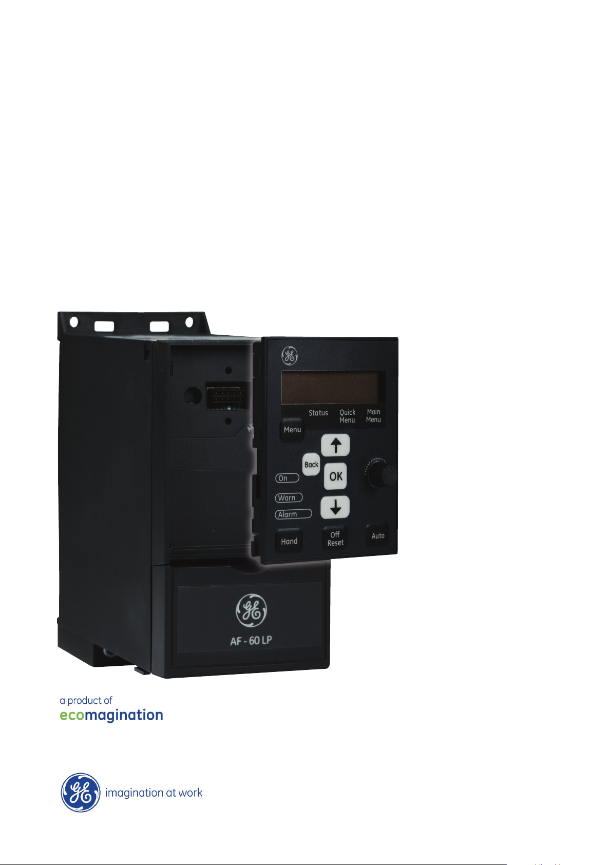
AF-60 LP
Operating Instructions
TM
Micro Drive
Page 2

Contents
AF-60 LP™ Micro Drive Operating Instructions
1 Safety
Safety Instructions 5
Software Version and Approvals 6
General Warning 7
Avoid unintended Start 7
Before Commencing Repair Work 8
2 Mechanical Installation
Before Starting 9
Mechanical Dimensions 10
3 Electrical Installation
How to Connect 11
Electrical Installation in General 11
Fuses 12
EMC-Correct Installation 13
Mains Connection 13
Motor Connection 14
5
9
11
Control Terminals 15
Connecting to Control Terminals 16
Switches 16
Power Circuit - Overview 17
Load sharing/Brake 18
4 Programming
How to Programme 19
Programming with DCT-10 Set-up Software 19
Programming with the Keypad 19
Status Menu 21
Quick Menu 21
Quick Menu Parameters 22
Main Menu 25
5 Modbus RTU
Modbus RTU Overview 27
Modbus RTU Message Framing Structure 28
19
27
Remote Terminal Unit 28
Modbus RTU Message Structure 28
Start/Stop Field 28
Address Field 29
Function Field 29
DET-579A
1
Page 3

AF-60 LP™ Micro Drive Operating Instructions
Data Field 29
CRC Check Field 29
Coil/Register Addressing 29
How to Control the frequency converter 31
Function Codes Supported by Modbus RTU 31
Exception and Error Codes 31
How to Access Parameters 32
Parameter Handling 32
Storage of Data 32
IND 32
Text Blocks 32
Conversion Factor 32
Parameter Values 32
Examples 33
Read Coil Status (01
Force/Write Single Coil (05
Force/Write Multiple Coils (0F
Read Holding Registers (03
Preset Single Register (06
Preset Multiple Registers (10
HEX
)
)
HEX
)
HEX
)
HEX
)
HEX
)
HEX
GE Drive Control Profile 37
Control Word According to GE Drive Control Profile 37
Explanation of the Control Bits 37
Status Word According to GE Drive Control Profile (STW) 39
Explanation of the Status Bits 40
Bus Speed Reference Value 41
6 Parameter Overview
Conversion Index 48
Change during operation 48
2-Set-up 48
Type 48
33
33
34
34
35
36
43
0-** Operation/Display 49
1-** Load/Motor 49
2-** Brakes 49
3-** Reference/Ramps 50
4-** Limits/Warnings 50
5-** Digital In/Out 50
6-** Analog In/Out 51
7-** Controllers 51
8-** Comm. and Options 51
2
DET-579A
Page 4

AF-60 LP™ Micro Drive Operating Instructions
13-** Logic Controller 52
14-** Special Functions 52
15-** Drive Information 52
16-** Data Readouts 53
7 Troubleshooting
Alarm, Warning and Extended Status Word 57
8 Specifications
Mains Supply 59
Other Specifications 62
Special Conditions 65
The Purpose of Derating 65
Derating for Ambient Temperature 65
Derating for Low Air Pressure 65
Derating for Running at Low Speeds 65
Options for AF-60 LP™ Micro Drive 66
Index
55
59
67
DET-579A
3
Page 5

1
AF-60 LP™ Micro Drive Operating Instructions
4
DET-579A
Page 6

AF-60 LP™ Micro Drive Operating Instructions
1 Safety
1.1.1 High Voltage Warning
The voltage of the frequency converter is dangerous whenever it is connected to mains. Incorrect installation of the motor or frequency
converter may cause damage to the equipment, serious injury or death. Consequently, it is essential to comply with the instructions in this
manual as well as local and national rules and safety regulations.
1.1.2 Safety Instructions
Prior to using functions directly or indirectly influencing personal safety (e.g. Fire Mode or other functions either forcing the motor to stop or
attempting to keep it functioning) a thorough risk analysis and system test must be carried through. The system tests must include testing
failure modes regarding the control signalling (analog and digital signals and serial communication.
• Make sure the frequency converter is properly connected to earth.
• Do not remove mains connections, motor connections or other power connections while the frequency converter is connected to power.
• Protect users against supply voltage.
• Protect the motor against overloading according to national and local regulations.
• The earth leakage current exceeds 3.5 mA.
• The [OFF] key is not a safety switch. It does not disconnect the frequency converter from mains.
1
DET-579A
5
Page 7
1.1.3 Software Version and Approvals
1
Operating Instructions
AF-60 LP™ Micro Drive
AF-60 LP™ Micro Drive Operating Instructions
Software Version
Series
This Operating Instructions can
be used for all AF-60 LP™ Micro
Drive frequency converters
with software version 2.1x.
The software version number
can be read in
parameter 15-43.
6
DET-579A
Page 8
1.1.4 General Warning
AF-60 LP™ Micro Drive Operating Instructions
Warning:
Touching the electrical parts may be fatal - even after the equipment has been disconnected from mains.
Also make sure that other voltage inputs have been disconnected (such as external DC bus power supplies).
Be aware that there may be high voltage on the DC link even when the LEDs are turned off.
Before touching any potentially live parts of the frequency converter, wait at least 4 minutes for all sizes.
Shorter time is allowed only if indicated on the nameplate for the specific unit.
Leakage Current
The earth leakage current from the frequency converter exceeds 3.5 mA. According to IEC 61800-5-1 a reinforced Protective Earth connection
must be ensured by means of a min. 10mm² Cu or an addtional PE wire - with the same cable cross section as the Mains wiring - must be
terminated separately.
Residual Current Device
This product can cause a DC current in the protective conductor. Where a residual current device (RCD) is used for extra protection, only an
RCD of Type B (time delayed) shall be used on the supply side of this product.
Protective earthing of the frequency converter and the use of RCDs must always follow national and local regulations.
Motor overload protection is possible by setting Parameter 1-90 Motor thermal protection to the value Electronic overload trip. For the North
American market: Electronic overload functions provide class 20 motor overload protection, in accordance with NEC.
Installation in high altitudes:
For altitudes above 2 km, please contact GE .
1
1.1.5 IT Mains
IT Mains
Installation on isolated mains source, i.e. IT mains.
Max. supply voltage allowed when connected to mains: 440 V.
As an option, GE offers line filters for improved harmonics performance.
1.1.6 Avoid unintended Start
While the frequency converter is connected to mains, the motor can be started/stopped using digital commands, bus commands, references or via the drive
Keypad.
• Disconnect the frequency converter from mains whenever personal safety considerations make it necessary to avoid unintended start of any motors.
• To avoid unintended start, always activate the [OFF] key before changing parameters.
DET-579A
7
Page 9

1.1.7 Disposal Instruction
1
1.1.8 Before Commencing Repair Work
1.
Disconnect AF-60 LP™ Micro Drive from mains (and external DC supply, if present.)
2. Wait for 4 minutes (M1, M2 and M3) and 15 minutes (M4 and M5) for discharge of the DC-link.
3. Disconnect DC bus terminals and brake terminals (if present)
4. Remove motor cable
AF-60 LP™ Micro Drive Operating Instructions
Equipment containing electrical components must not be disposed of together with domestic waste.
It must be separately collected with electrical and electronic waste according to local and currently valid legislation.
8
DET-579A
Page 10
2 Mechanical Installation
2.1 Before Starting
AF-60 LP™ Micro Drive Operating Instructions
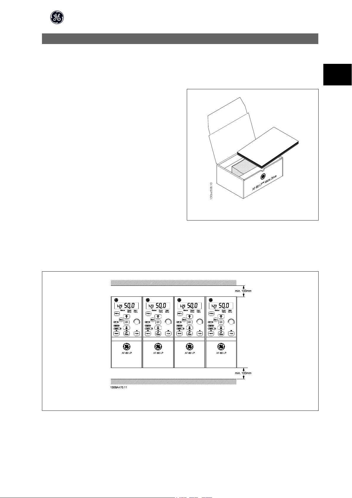
2.1.1 Checklist
When unpacking the frequen cy converter, make sure that the unit is undam-
aged and complete. Check that the packaging contains the following:
•
AF-60 LP™ Micro Drive
•Quick Guide
2.2 Side-by-Side Installation
2
Illustration 2.1: Content of box.
The frequency converter can be mounted side-by-side for IP 20 rating units and requires 100 mm or 3.94 inclearance above and below for cooling. Regarding
surroundings in general, please see chapter 7. Specifications.
Illustration 2.2: Side-by-side installation.
DET-579A
9
Page 11
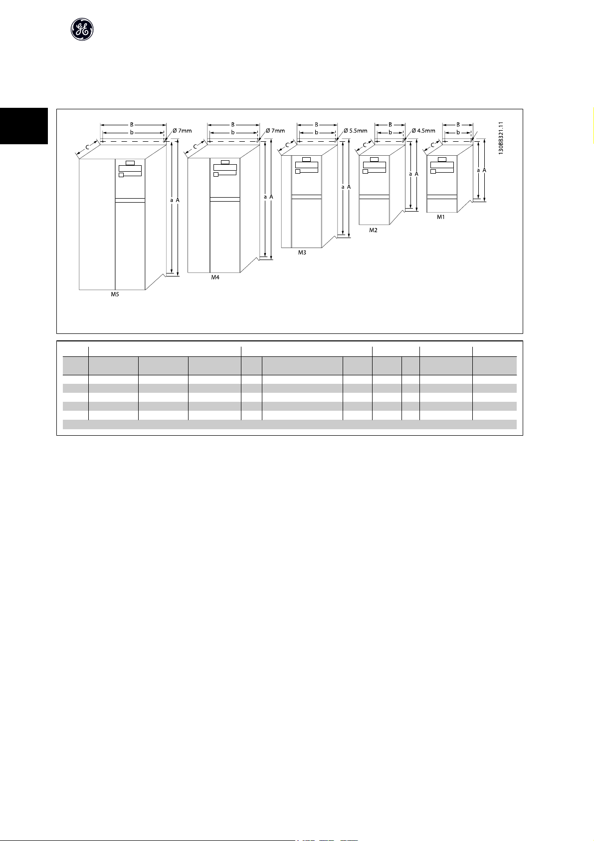
2.3.1 Mechanical Dimensions
A template for drilling can be found on the flap of the packaging.
2
Illustration 2.3: Mechanical dimensions.
AF-60 LP™ Micro Drive Operating Instructions
1)
Unit
1 X 200-240 V 3 X 200 -240 V 3 X 380-480 V A A (incl. decoupling plate) a B b C Kg
Size
M1 0.18 - 0.75 0.25 - 0.75 0.37 - 0.75 150 205 140.4 70 55 148 1.1
M2 1.5 1.5 1.5 - 2.2 176 230 166.4 75 59 168 1.6
M3 2.2 2.2 -3.7 3.0 - 7.5 239 294 226 90 69 194 3.0
M4 11.0-15.0 292 347.5 272.4 125 97 241 6.0
M5 18.5-22.0 335 387.5 315 165 140 248 9.5
1)
For Keypad with potentiometer, please add 7.6 mm.
Table 2.1: Mechanical Dimensions
Power (kW) Height (mm) Width (mm)
Depth
(mm)
Max. Weight
10
DET-579A
Page 12
3 Electrical Installation
3.1 How to Connect
3.1.1 Electrical Installation in General
AF-60 LP™ Micro Drive Operating Instructions
NB!
All cabling must comply with national and local regulations on cable cross-sections and ambient temperature. Copper conductors required, (60-75° C) recom-
mended.
Details of terminal tightening torques.
Power (kW) Torque (Nm)
Unit Size 1 x 200-240 V 3 x 200-240 V 3 x 380-480 V Line Motor DC connection/Brake Control Terminals Earth Relay
M1 0.18 - 0.75 0.25 - 0.75 0.37 - 0.75 1.4 0.7
M2 1.5 1.5 1.5 - 2.2 1.4 0.7
M3 2.2 2.2 - 3.7 3.0 - 7.5 1.4 0.7
M4 11.0-15.0 1.3 1.3 1.3 0.15 3 0.5
M5 18.5-22.0 1.3 1.3 1.3 0.15 3 0.5
1)
Spade connectors (6.3 mm Faston plugs)
Table 3.1: Tightening of terminals.
Spade
Spade
Spade
1)
1)
1)
0.15 3 0.5
0.15 3 0.5
0.15 3 0.5
3
DET-579A
11
Page 13

AF-60 LP™ Micro Drive Operating Instructions
3.1.2 Fuses
Branch circuit protection:
In order to protect the installation against electrical and fire hazard, all branch circuits in an installation, switch gear, machines etc., must be short-circuited and
overcurrent protected according to national/international regulations.
Short circuit protection:
GE Drive is suitable for a circuit capable of supplying a maximum of 100,000 A
(symmetrical), 480 V maximum.
rms
3
Overcurrent protection:
Provide overload protection to avoid overheating of the cables in the installation. Overcurrent protection must always be carried out according to national
regulations.
Non UL compliance:
If UL/cUL is not to be complied with, GE recommends using the fuses mentioned in the below table, which will ensure compliance with EN50178/IEC61800-5-1:
In case of malfunction, not following the fuse recommendation may result in damage to the frequency converter.
Max. fuses UL
Bussmann Bussmann Bussmann Littel fuse
1 X 200-240 V
Type RK1 Type J Type T Type RK1 Type CC Type RK1 Type gG
1/4 - 1/2 KTN-R15 JKS-15 JJN-15 KLN-R15 ATM-R15 A2K-15R 16A
1 KTN-R25 JKS-25 JJN-25 KLN-R25 ATM-R25 A2K-25R 25A
2 KTN-R35 JKS-35 JJN-35 KLN-R35 - A2K-35R 35A
3 KTN-R50 JKS-50 JJN-50 KLN-R50 - A2K-50R 50A
3 x 200-240 V
1/3 KTN-R10 JKS-10 JJN-10 KLN-R10 ATM-R10 A2K-10R 10A
1/2 KTN-R15 JKS-15 JJN-15 KLN-R15 ATM-R15 A2K-15R 16A
1 KTN-R20 JKS-20 JJN-20 KLN-R20 ATM-R20 A2K-20R 20A
2 KTN-R25 JKS-25 JJN-25 KLN-R25 ATM-R25 A2K-25R 25A
3 KTN-R40 JKS-40 JJN-40 KLN-R40 ATM-R40 A2K-40R 40A
5 KTN-R40 JKS-40 JJN-40 KLN-R40 - A2K-40R 40A
3 x 380-480 V
1/2 - 1 KTS-R10 JKS-10 JJS-10 KLS-R10 ATM-R10 A6K-10R 10A
2 KTS-R15 JKS-15 JJS-15 KLS-R15 ATM-R15 A2K-15R 16A
3 KTS-R20 JKS-20 JJS-20 KLS-R20 ATM-R20 A6K-20R 20A
4 KTS-R40 JKS-40 JJS-40 KLS-R40 ATM-R40 A6K405R 40A
5 KTS-R40 JKS-40 JJS-40 KLS-R40 ATM-R40 A6K-40R 40A
7.5 KTS-R40 JKS-40 JJS-40 KLS-R40 - A6K-40R 40A
10 KTS-R40 JKS-40 JJS-40 KLS-R40 - A6K-40R 40A
15 KTS-R60 JKS-60 JJS-60 KLS-R60 - A6K-60R 63A
20 KTS-R60 JKS-60 JJS-60 KLS-R60 - A6K-60R 63A
25 KTS-R60 JKS-60 JJS-60 KLS-R60 - A6K-60R 80A
30 KTS-R60 JKS-60 JJS-60 KLS-R60 - A6K-60R 80A
Table 3.2: Fuses
Ferraz-
Shawmut
Ferraz-
Shawmut
Max. fuses non UL
12
DET-579A
Page 14
AF-60 LP™ Micro Drive Operating Instructions
3.1.3 EMC-Correct Installation
Following these guidelines is advised, where compliance with EN 61000-6-3/4, EN 55011 or EN 61800-3 First environment is required. If the installation is in EN
61800-3 Second environment, then it is acceptable to deviate from these guidelines. It is however not recommended.
Good engineering practice to ensure EMC-correct electrical installation:
• Use only braided screened/armoured motor cables and control cables.
The screen should provide a minimum coverage of 80%.The screen material must be metal, not limited to but typically copper, aluminium, steel or lead.
There are no special requirements for the mains cable.
• Installations using rigid metal conduits are not required to use screened cable, but the motor cable must be installed in conduit separate from the control
and mains cables. Full connection of the conduit from the drive to the motor is required. The EMC performance of flexible conduits varies a lot and
information from the manufacturer must be obtained.
• Connect the screen/armour/conduit to earth at both ends for motor cables and control cables.
• Avoid terminating the screen/armour with twisted ends (pigtails). Such a termination increases the high frequency impedance of the screen, which
reduces its effectiveness at high frequencies. Use low impedance cable clamps or glands instead.
• Ensure good electrical contact between the de-coupling plate and the metal chassis of the frequency converter, see Instruction
• Avoid using unscreened/unarmoured motor or control cables inside cabinets housing the drive(s), where possible.
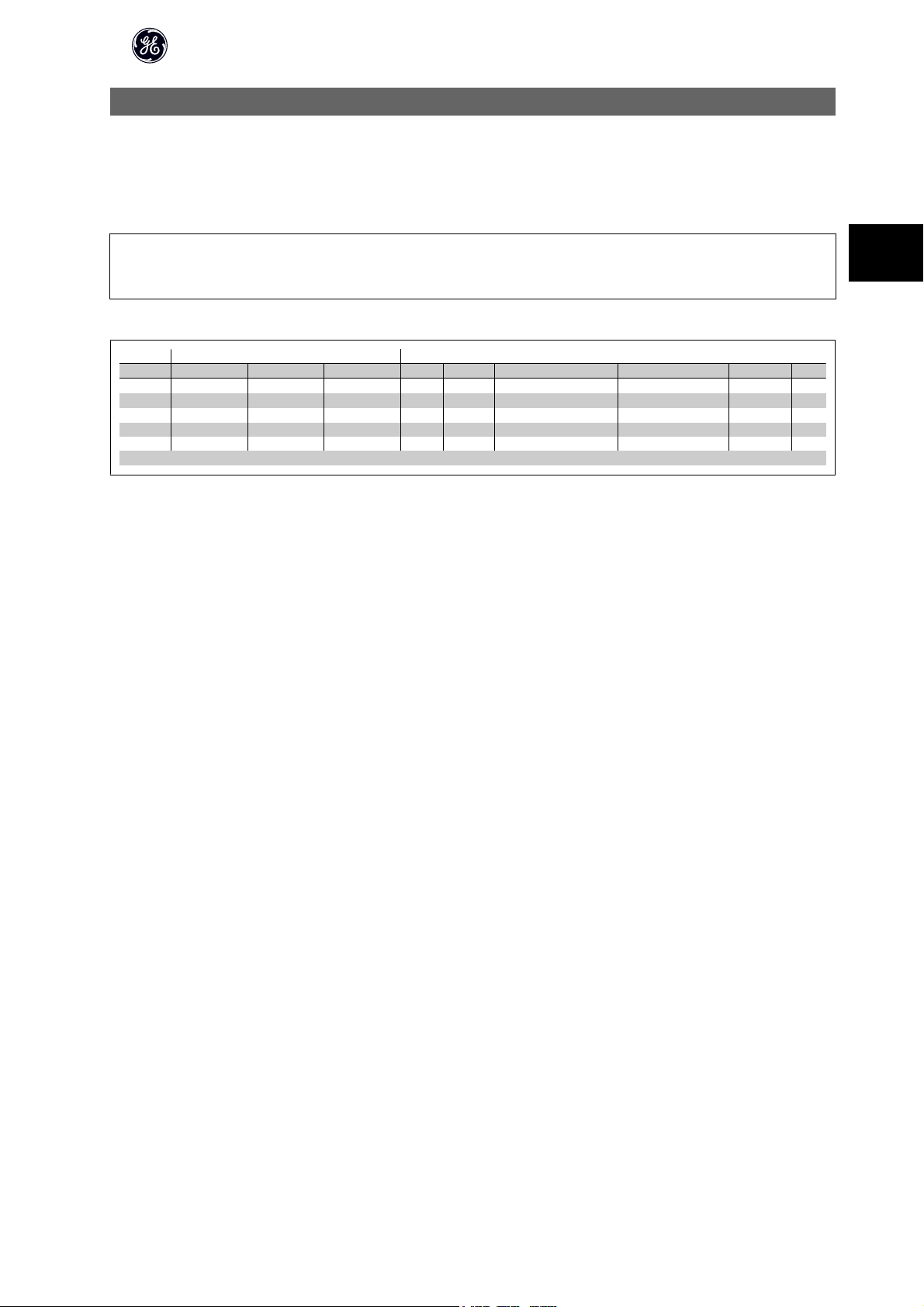
3.2 Mains Connection
3
3.2.1 Connecting to Mains
Step 1: First mount earth cable.
Step 2: Mount wires in terminals L1/L, L2 and L3/N and tighten.
For 3-phase connection, connect wires to all three terminals.
For single-phase connection, connect wires to terminals L1/L and L3/N.
Illustration 3.1: Mounting of earth cable and mains wires.
Illustration 3.2: Three-phase and single-phase wire connec-
tions.
DET-579A
13
Page 15

3.3 Motor Connection
3.3.1 How to Connect the Motor
See the chapter Specifications for correct dimensioning of motor cable cross-section and length.
• Use a shielded/armored motor cable to comply with EMC emission specifications, and connect this cable to both the decoupling plate and the motor
3
metal.
• Keep motor cable as short as possible to reduce the noise level and leakage currents.
All types of three-phased asynchronous standard motors can be connected
to the frequency converter. Normally, small motors are star-connected
(230/400 V, Δ/Y). Large motors are delta-connected (400/690 V, Δ/Y). Refer to
motor nameplate for correct connection and voltage.
AF-60 LP™ Micro Drive Operating Instructions
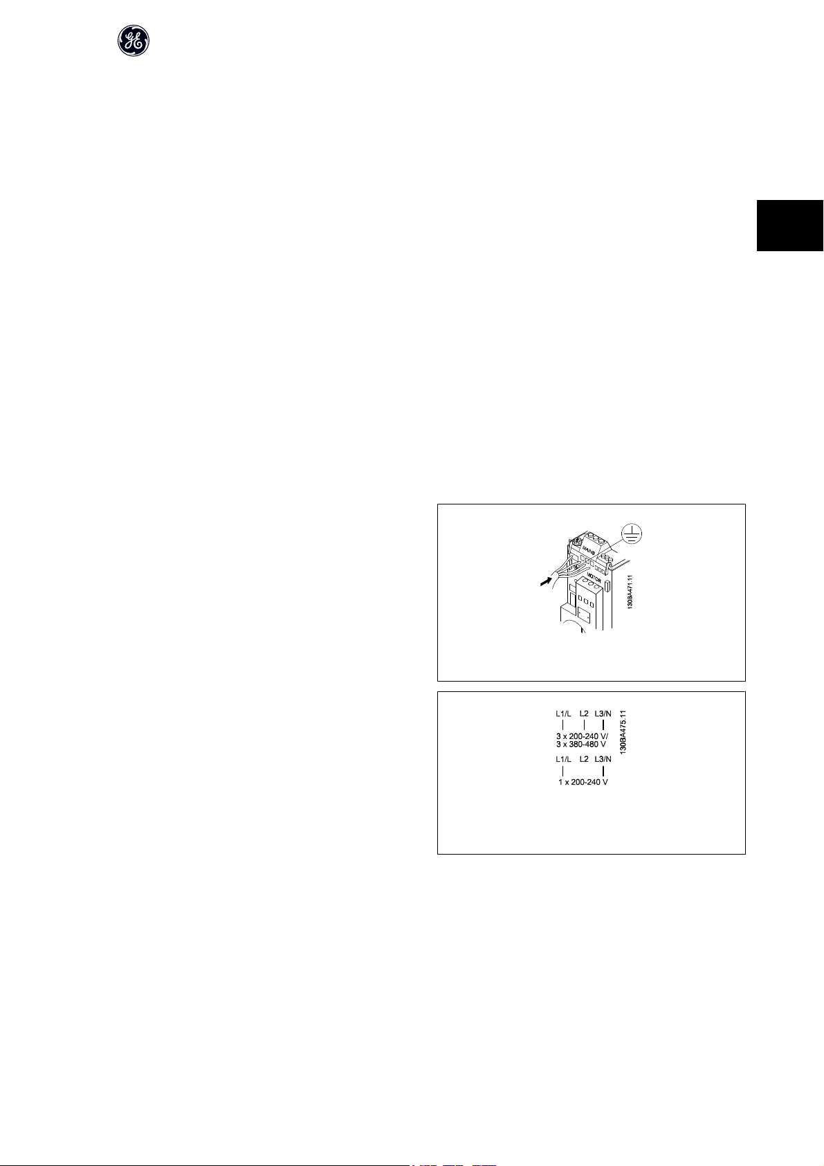
Step 1: First, mount the earth cable.
Step 2: Connect wires to terminals either in star or delta-connection. See mo-
tor nameplate for further information.
Illustration 3.3: Star and delta connections.
Illustration 3.4: Mounting of earth cable and motor wires.
14
DET-579A
Page 16
For EMC correct installation, use optional de-coupling plate, see chapter Op-
tions for frequency converter.
3.4 Control Terminals
3.4.1 Access to Control Terminals
All control cable terminals are located underneath the terminal cover in front
of the frequency converter. Remove the terminal cover using a screwdriver.
AF-60 LP™ Micro Drive Operating Instructions
3
Illustration 3.5: Frequency converter with de-coupling plate
NB!
See back of terminal cover for outlines of control terminals and switches.
Illustration 3.6: Removing terminal cover.
DET-579A
15
Page 17
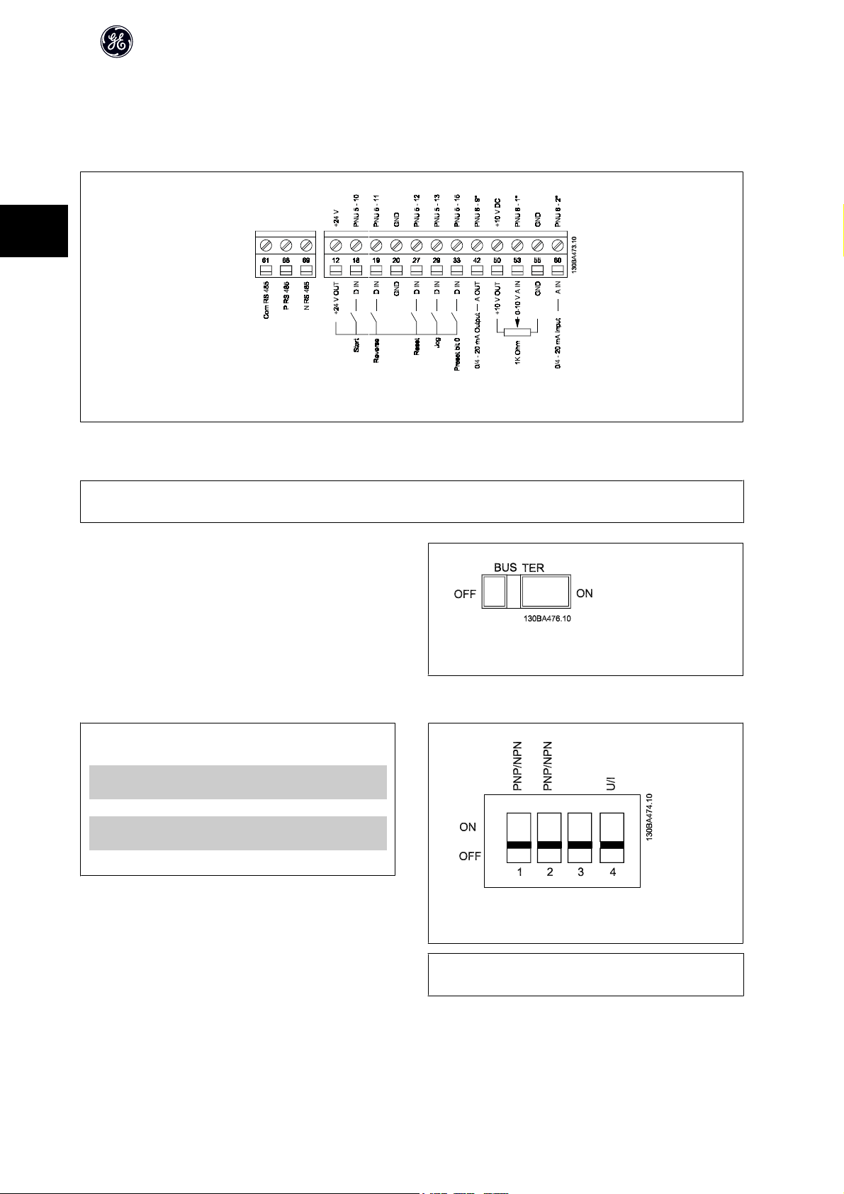
AF-60 LP™ Micro Drive Operating Instructions
3.4.2 Connecting to Control Terminals
This illustration shows all control terminals of the frequency converter. Applying Start (term. 18) and an analog reference (term. 53 or 60) make the frequency
converter run.
3
Illustration 3.7: Overview of control terminals in PNP-configuration and factory setting.
3.5 Switches
NB!
Do not operate switches with power on the frequency converter.
Bus termination:
Switch BUS TER pos. ON terminates the RS485 port, terminals 68, 69. See
power circuit drawing.
Default setting = Off.
S200 Switches 1-4:
Switch 1: *OFF = PNP terminals 29
ON = NPN terminals 29
Switch 2: *OFF = PNP terminal 18, 19, 27 and 33
ON = NPN terminal 18, 19, 27 and 33
Switch 3: No function
Switch 4: *OFF = Terminal 53 0 - 10 V
ON = Terminal 53 0/4 - 20 mA
* = default setting
Table 3.3: Settings for S200 Switches 1-4
Illustration 3.8: S640 Bus termination.
Illustration 3.9: S200 Switches 1-4.
16
NB!
Parameter 6-19 must be set according to Switch 4 position.
DET-579A
Page 18
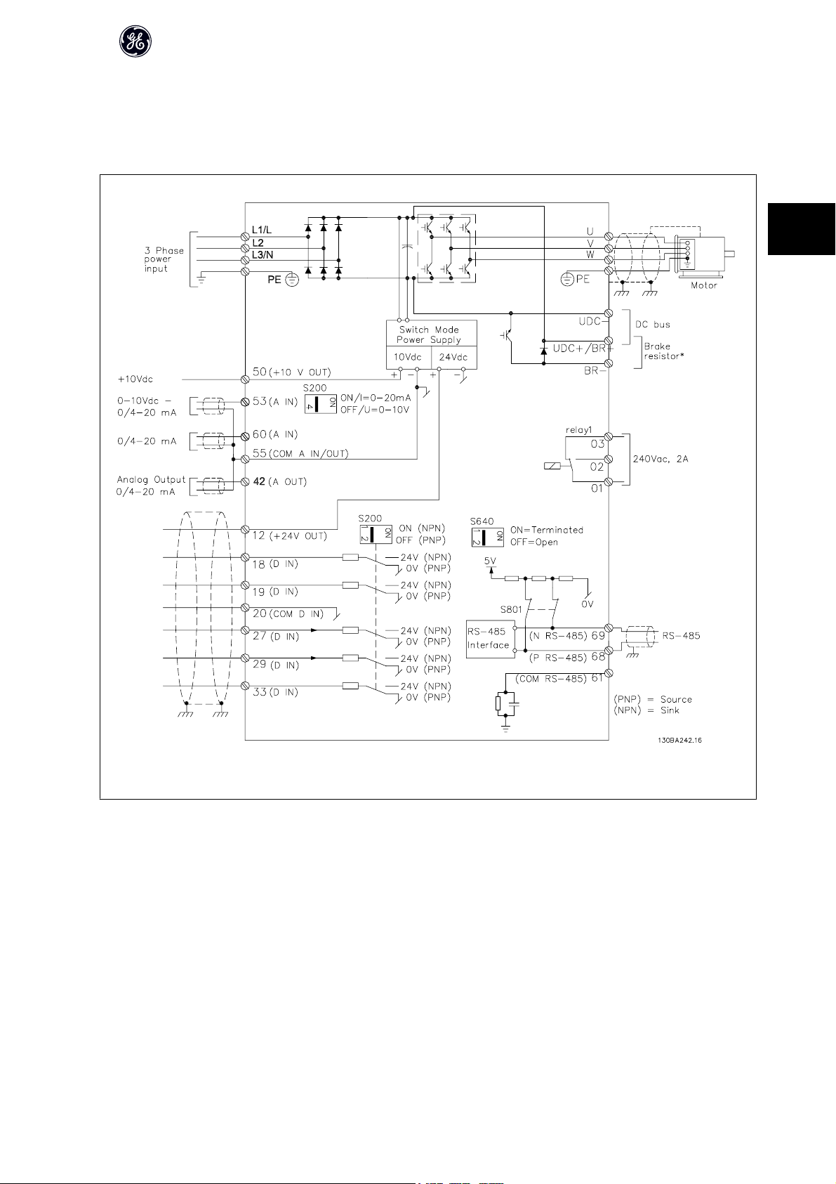
3.6 Power Circuit - Overview
3.6.1 Power Circuit - Overview
AF-60 LP™ Micro Drive Operating Instructions
3
Illustration 3.10: Diagram showing all electrical terminals.
* Brake (BR+ and BR-) are not applicable for Unit Size M1.
Brake resistors are available from GE.
Improved power factor and EMC performance can be achieved by installing optional GE line filters.
GE power filters can also be used for load sharing.
DET-579A
17
Page 19

3.6.2 Load sharing/Brake
Use 6.3 mm insulated Faston Plugs designed for high voltage for DC (Load Sharing and brake).
Load sharing: Connect terminals UDC- and UDC/BR+.
Brake: Connect terminals BR- and UDC/BR+ (Not applicable for Unit Size M1).
AF-60 LP™ Micro Drive Operating Instructions
3
Note that voltage levels of up to 850 V DC may occur between terminals
UDC+/BR+ and UDC-. Not short circuit protected.
18
DET-579A
Page 20
AF-60 LP™ Micro Drive Operating Instructions
4 Programming
4.1 How to Programme
4.1.1 Programming with DCT-10 Set-up Software
The frequency converter can be programmed from a PC via RS485 com-port by installing the DCT-10 Set-up Software.
This software can be downloaded from the GE Web site: www.geelectrical.com/drives
4.1.2 Programming with the Keypad
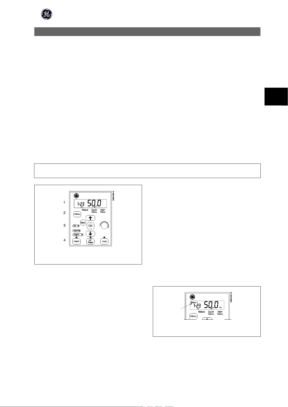
The Keypad is divided into four functional groups:
1. Numeric display.
2. Menu key.
3. Navigation keys.
4. Operation keys and indicator lights (LEDs).
NB!
Parameters should be changed in numerical order. Certain parameter values are affected by preceding changes.
4
Illustration 4.1: Keypad with potentiometer
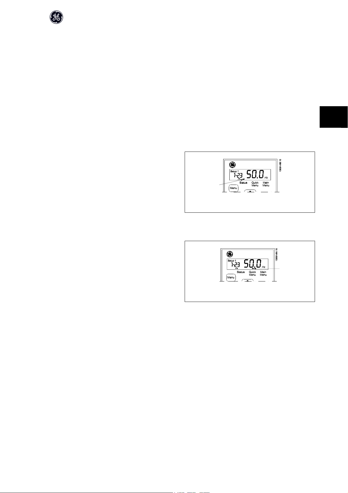
The display:
A number of information can be read from the display.
Set-up number shows the active set-up and the edit set-up. If the same set-
up acts as both active and edit set-up, only that set-up number is shown
(factory setting).
When active and edit set-up differ, both numbers are shown in the display
(Setup 12). The number flashing, indicates the edit set-up.
DET-579A
Illustration 4.2: Indicating Set-up
19
Page 21
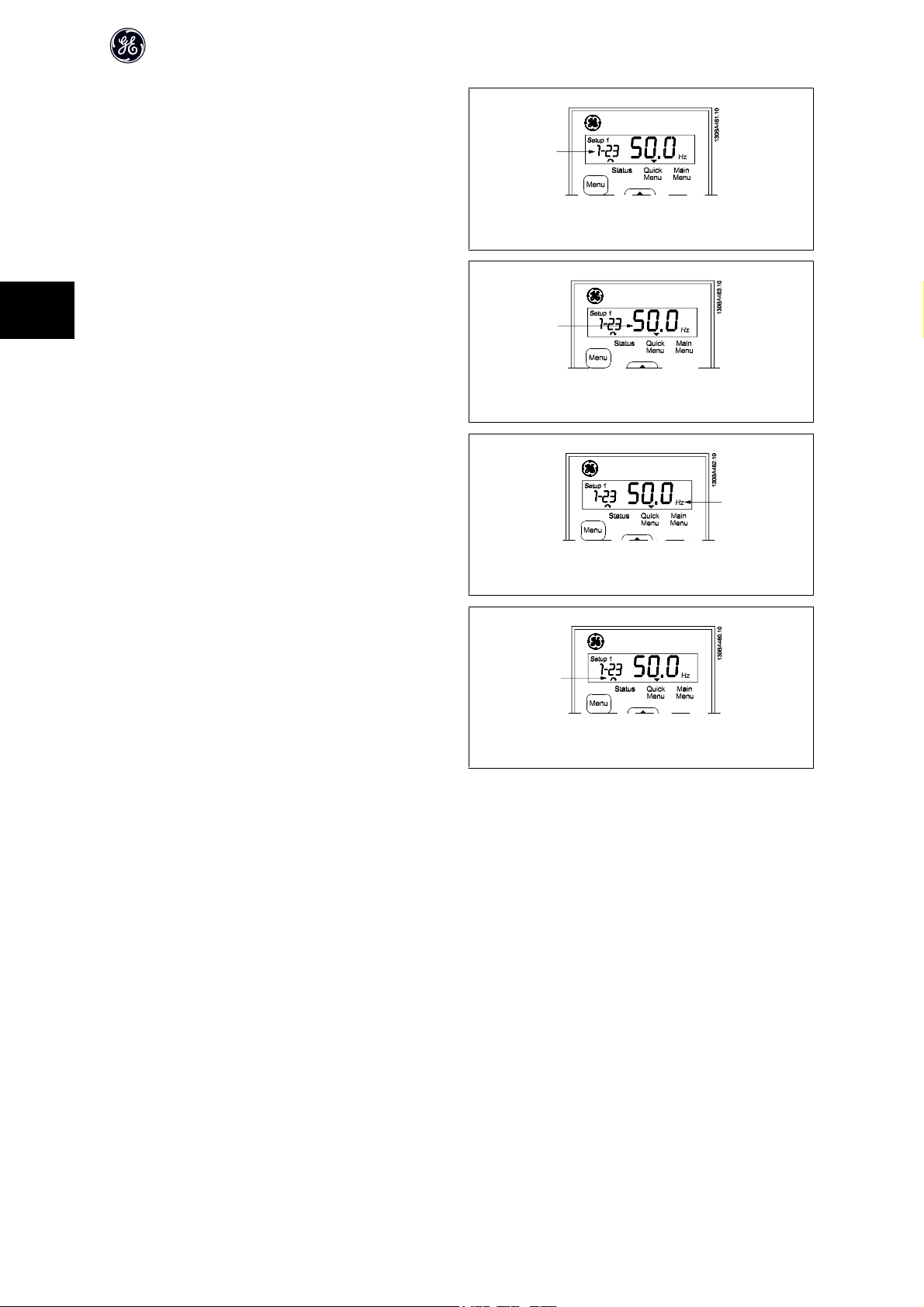
The small digits to the left are the selected parameter number.
The large digits in the middle of the display show the value of the selected
parameter.
4
The right side of the display shows the unit of the selected parameter. This
can be either Hz, A, V, kW, HP, %, s or RPM.
AF-60 LP™ Micro Drive Operating Instructions
Illustration 4.3: Indicating selected par. no.
Illustration 4.4: Indicating value of selected par.
Illustration 4.5: Indicating unit of selected par.
Motor direction is shown to the bottom left of the display - indicated by a
small arrow pointing either clockwise or counterclockwise.
Illustration 4.6: Indicating motor direction
Use the [MENU] key to select one of the following menus:
Status Menu:
The Status Menu is either in Readout Mode or Hand Mode. In Readout Mode the value of the currently selected readout parameter is shown in the display.
In Hand Mode the local Keypad reference is displayed.
Quick Menu:
Displays Quick Menu parameters and their settings. Parameters in the Quick Menu can be accessed and edited from here. Most applications can be run by setting
the parameters in the Quick Menus.
Main Menu:
Displays Main Menu parameters and their settings. All parameters can be accessed and edited here. A parameter overview is found later in this manual.
Indicator lights:
• Green LED: The frequency converter is on.
• Yellow LED: Indicates a warning. Please see section Troubleshooting
• Flashing red LED: Indicates an alarm. Please see section Troubleshooting
20
DET-579A
Page 22
AF-60 LP™ Micro Drive Operating Instructions
Navigation Keys:
[Back]: For moving to the previous step or layer in the navigation structure.
Arrows [
[OK]: For selecting a parameter and for accepting changes to parameter settings.
Operation Keys:
A yellow light above the operation keys indicates the active key.
[Hand ]: Starts the motor and enables control of the frequency converter via the Keypad.
[Off/Reset]: The motor stops except in alarm mode. In that case the motor will be reset.
[Auto ]: The frequency converter is controlled either via control terminals or serial communication.
[Potentiometer] Keypad: The potentiometer works in two ways depending on the mode in which the frequency converter is running.
In Auto Mode the potentiometer acts as an extra programmable analog input.
In Hand Mode the potentiometer controls local reference.
] [▼]: For maneuvering between parameter groups, parameters and within parameters.
▲
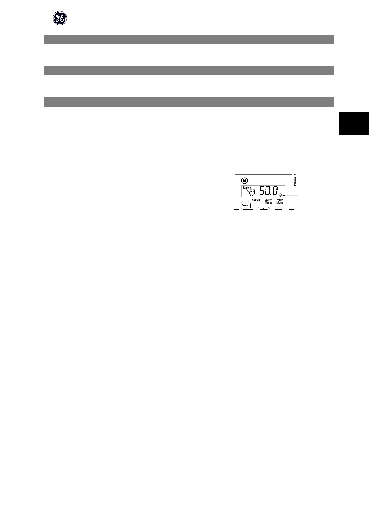
4.2 Status Menu
After power up the Status Menu is active. Use the [MENU] key to toggle be-
tween Status, Quick Menu and Main Menu.
4
Arrows [
The display indicates the status mode with a small arrow above “Status”.
] and [▼] toggles between the choices in each menu.
▲
4.3 Quick Menu
The Quick Menu gives easy access to the most frequently used parameters.
1. To enter the Quick Menu, press [MENU] key until indicator in display
is placed above Quick Menu.
2.
3.
4. Press [OK] to select a parameter.
5.
6. Press [OK] to accept the change.
7. To exit, press either [Back] twice to enter Status, or press [Menu]
] [▼] to select either QM1 or QM2, then press [OK].
Use [
▲
Use [
] [▼] to browse through the parameters in the Quick Menu.
▲
] [▼] to change the value of a parameter setting.
Use [
▲
once to enter Main Menu.
Illustration 4.7: Indicating Status mode
Illustration 4.8: Indicating Quick Menu mode
DET-579A
21
Page 23

4.4 Quick Menu Parameters
4.4.1 Quick Menu Parameters - Basic Settings QM1
Below are descriptions of all parameters found in the Quick Menu.
* = Factory setting.
AF-60 LP™ Micro Drive Operating Instructions
4
1-20 Motor Power [kW]/[HP] (P
m.n
)
Option: Function:
Enter motor power from nameplate data.
Two sizes down, one size up from nominal AF-60 LP™ rating.
[1] 0.09 kW/0.12 HP
[2] 0.12 kW/0.16 HP
[3] 0.18kW/0.25 HP
[4] 0.25 kW/0.33 HP
[5] 0.37kW/0.50 HP
[6] 0.55 kW/0.75 HP
[7] 0.75 kW/1.00 HP
[8] 1.10 kW/1.50 HP
[9] 1.50 kW/2.00 HP
[10] 2.20 kW/3.00 HP
[11] 3.00 kW/4.00 HP
[12] 3.70 kW/5.00 HP
[13] 4.00 kW/5.40 HP
[14] 5.50 kW/7.50 HP
[15] 7.50 kW/10.0 HP
[16] 11.00 kW/15.00 HP
[17] 15.00 kW/20.00 HP
[18] 18.50 kW/25.00 HP
[19] 22.00 kW/29.50 HP
[20] 30.00 kW/40.00 HP
NB!
Changing this parameter affects par. 1-22 to 1-25, 1-30, 1-33 and 1-35.
1-22 Motor Voltage (U
m.n
)
Range: Function:
230/400 V [50 - 999 V] Enter motor voltage from nameplate data.
1-23 Motor Frequency (f
m.n
)
Range: Function:
60 Hz* [20-400 Hz] Enter motor frequency from nameplate data.
1-24 Motor Current (I
m.n
)
Range: Function:
M-type de-
pendent*
22
[0.01 - 100.00 A] Enter motor current from nameplate data.
DET-579A
Page 24

AF-60 LP™ Micro Drive Operating Instructions
1-25 Motor Nominal Speed (n
m.n
)
Range: Function:
M-type De-
pendent*
[100 - 9999 RPM] Enter motor nominal speed from nameplate data.
1-29 Auto Tune
Option: Function:
Use Auto Tune to optimize motor performance.
NB!
This parameter cannot be changed while motor runs.
1. Stop the frequency converter – make sure motor is at standstill
2. Choose [2] Enable Auto Tune
3. Apply start signal
– Via Keypad: Press Hand
- Or in Remote On mode: Apply start signal on terminal 18
[0] * Off Auto Tune function is disabled.
[2] Enable Auto Tune Auto Tune function starts running.
NB!
To gain optimum tuning of frequency converter, run Auto Tune on a cold motor.
3-02 Minimum Reference
Range: Function:
0.00* [-4999 - 4999] Enter value for minimum reference.
The sum of all internal and external references are clamped (limited) to the minimum reference value,
par. 3-02.
4
3-03 Maximum Reference
Range: Function:
Maximum Reference is adjustable in the range Minimum Reference - 4999.
50.00* [-4999 - 4999] Enter value for Maximum Reference.
The sum of all internal and external references are clamped (limited) to the maximum reference value,
par. 3-03.
3-41 Accel Time 1
Range: Function:
3.00 s* [0.05 - 3600.00 s ] Enter accel time from 0 Hz to rated motor frequency (f
Choose a accel time ensuring that torque limit is not exceeded, see par. 4-16.
) set in par. 1-23.
M,N
3-42 Decel Time 1
Range: Function:
3.00* [0.05 - 3600.00 s] Enter decel time from rated motor frequency (f
Choose a decel time that does not cause over-voltage in due to regenerative operation of motor. Fur-
thermore, regenerative torque must not exceed limit set in par. 4-17.
) in par. 1-23 to 0 Hz.
M,N
4.4.2 Quick Menu Parameters - PI Basic Settings QM2
The following is a brief description of the parameters for the PI Basic Settings. For a more detailed description, please see AF-60 LP™ Micro Drive Programming
Guide.
1-00 Configuration Mode
Range: Function:
[] Choose [3] Process Closed Loop
DET-579A
23
Page 25

4
AF-60 LP™ Micro Drive Operating Instructions
3-02 Min. Reference
Range: Function:
[-4999 - 4999] Sets limits for set-point and feedback.
3-03 Max. Reference
Range: Function:
[-4999 - 4999] Sets limits for set-point and feedback.
3-10 Preset Reference
Range: Function:
[-100.00 - 100.00] Preset [0] works as set-point.
4-12 Motor Speed Low Limit
Range: Function:
[0.0 - 400 Hz] Lowest possible output frequency.
4-14 Motor Speed High Limit
Range: Function:
[0.0 - 400.00 Hz] Highest possible output frequency.
6-22 Terminal 60 Low Current
Range: Function:
[0.00 - 19.99 mA] Normally set to 0 or 4 mA.
6-23 Terminal 60 High Current
Range: Function:
[0.01 - 20.00 mA] Normally (default) set to 20 mA.
6-24 Terminal 60 Low Feedback Value
Range: Function:
[-4999 - 4999] Value corresponding to P. 6-22 setting.
6-25 Terminal 60 High Feedback Value
Range: Function:
[-4999 - 4999] Value corresponding to P. 6-23 setting.
6-26 Terminal 60 Filter Time Constant
Range: Function:
[0.01 - 10.00 s] Filter for suppressing electrical noise.
7-20 Process CL Feedback Resource
Range: Function:
[] Choose [2] analog input 60.
7-30 Process PI Normal/Inverse
Range: Function:
[] Most PI controllers are “Normal”.
7-31 Process PI Anti Windup
Range: Function:
[] Leave Enabled normally.
7-32 Process PI Start Speed
Range: Function:
[0.0 - 200.0 Hz] Choose expected normal running speed.
24
DET-579A
Page 26
7-33 Process PI Proportional Gain
Range: Function:
[0.00 - 10.00] Enter the P-factor.
7-34 Process PI Integral Time
Range: Function:
[0.10 - 9999.00 s] Enter the I-factor.
7-38 Process Feed Forward Factor
Range: Function:
[0 - 400%] Only applicable with changing set-points.
4.5 Main Menu
The Main Menu gives access to all parameters.
1. To enter the Main Menu, press [MENU] key until indicator in display
is placed above Main Menu.
2.
Use [
] [▼] to browse through the parameter groups.
▲
3. Press [OK] to select a parameter group.
4.
5. Press [OK] to select the parameter.
6.
7. Press [OK] to accept the value.
8. To exit, press either [Back] twice to enter Quick Menu, or press
] [▼] to browse through the parameters in the specific group.
Use [
▲
] [▼] to set/change the parameter value.
Use [
▲
[Menu] once to enter Status.
AF-60 LP™ Micro Drive Operating Instructions
4
Illustration 4.9: Indicating Main Menu mode
DET-579A
25
Page 27

5
AF-60 LP™ Micro Drive Operating Instructions
26
DET-579A
Page 28

AF-60 LP™ Micro Drive Operating Instructions
5 Modbus RTU
5.1 Modbus RTU Overview
5.1.1 Assumptions
These operating instructions assume that the installed controller supports the interfaces in this document and that all the requirements stipulated in the controller,
as well as the frequency converter, are strictly observed, along with all limitations therein.
5.1.2 What the User Should Already Know
The Modbus RTU (Remote Terminal Unit) is designed to communicate with any controller that supports the interfaces defined in this document. It is assumed that
the user has full knowledge of the capabilities and limitations of the controller.
5.1.3 Modbus RTU Overview
Regardless of the type of physical communication networks, the Modbus RTU Overview describes the process a controller uses to request access to another
device. This includes how it will respond to requests from another device, and how errors will be detected and reported. It also establishes a common format for
the layout and contents of message fields.
During communications over a Modbus RTU network, the protocol determines how each controller will learn its device address, recognise a message addressed
to it, determine the kind of action to be taken, and extract any data or other information contained in the message. If a reply is required, the controller will construct
the reply message and send it.
Controllers communicate using a master-slave technique in which only one device (the master) can initiate transactions (called queries). The other devices (slaves)
respond by supplying the requested data to the master, or by taking the action requested in the query.
The master can address individual slaves, or can initiate a broadcast message to all slaves. Slaves return a message (called a response) to queries that are
addressed to them individually. No responses are returned to broadcast queries from the master. The Modbus RTU protocol establishes the format for the master’s
query by placing into it the device (or broadcast) address, a function code defining the requested action, any data to be sent, and an error-checking field. The
slave’s response message is also constructed using Modbus protocol. It contains fields confirming the action taken, any data to be returned, and an error- checking
field. If an error occurs in receipt of the message, or if the slave is unable to perform the requested action, the slave will construct an error message and send it
in response, or a time-out will occur.
5
5.1.4 Frequency Converter with Modbus RTU
The frequency converter communicates in Modbus RTU format over the built-in RS-485 interface. Modbus RTU provides access to the Control Word and Bus
Reference of the frequency converter.
The Control Word allows the Modbus master to control several important functions of the frequency converter:
•Start
• Stop of the frequency converter in various ways:
Coast stop
Quick stop
DC Brake stop
Normal (accel/decel) stop
• Reset after a fault trip
• Run at a variety of preset speeds
• Run in reverse
• Change the active set-up
• Control the frequency converter’s built-in relay
The Bus Reference is commonly used for speed control. It is also possible to access the parameters, read their values, and where possible, write values to them.
This permits a range of control options, including controlling the setpoint of the frequency converter when its internal PI controller is used.
DET-579A
27
Page 29

AF-60 LP™ Micro Drive Operating Instructions
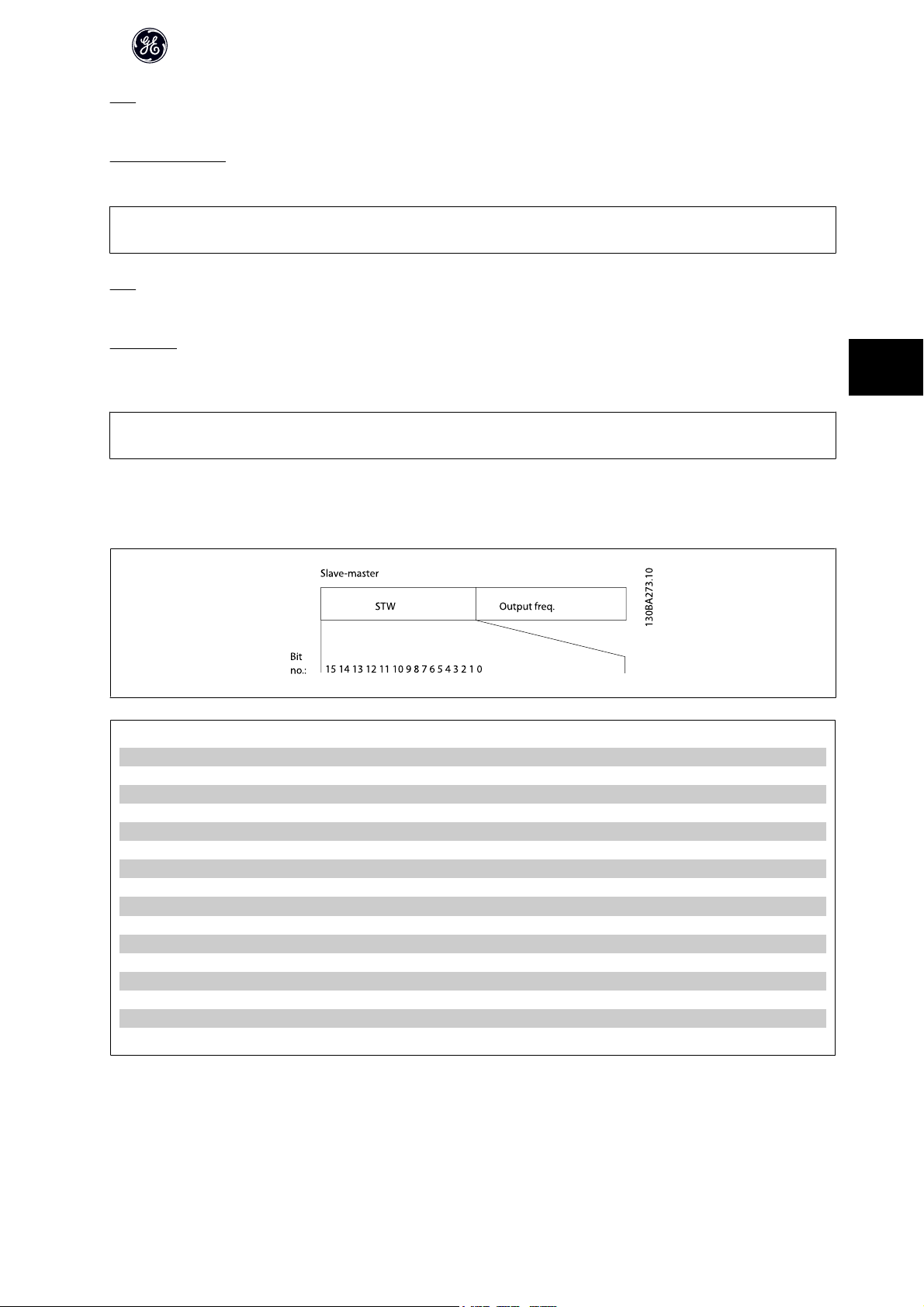
5.2 Modbus RTU Message Framing Structure
5.2.1 Remote Terminal Unit
The controllers are set up to communicate on the Modbus network using RTU (Remote Terminal Unit) mode, with each 8-bit byte in a message containing two 4-
bit hexadecimal characters.
The format for each byte is shown below.
Start bit Data bit Stop/parity Stop
5
Coding system: 8-bit binary, hexadecimal 0-9, A-F. Two hexadecimal characters contained in each 8-bit field of the
message.
Bits per byte: 1 start bit
8 data bits, least significant bit sent first
Parity: 1 bit for even/odd parity is used; 1 or 2 stop bits if no parity is selected (see par. 8-33).
Error Check Field: Cyclical Redundancy Check (CRC).
5.2.2 Modbus RTU Message Structure
The transmitting device places a Modbus RTU message into a frame with a known beginning and ending point. This allows receiving devices to begin at the start
of the message, read the address portion, determine which device is addressed (or all devices, if the message is broadcast), and to recognise when the message
is completed. Partial messages are detected and errors set as a result - or timeouts occur. Characters for transmission must be in hexadecimal 00 to FF format
in each field.
The frequency converter continuously monitors the network bus, also during “silent” intervals. When the first field (the address field) is received, each frequency
converter or device decodes it to determine which device is being addressed. Modbus RTU messages addressed to zero are broadcast messages. No response
is permitted for boradcast messages. A typical message frame is shown below.
Start Address Function Data CRC check End
T1-T2-T3-T4 1 byte 1 byte N x 1 byte 2 bytes T1-T2-T3-T4
Table 5.1: Typical Modbus RTU Message Structure
5.2.3 Start/Stop Field
Messages start with a silent period of at least 3.5 character intervals. This is implemented as a multiple of character intervals at the selected network baud rate
(shown as Start T1-T2-T3-T4). The first field to be transmitted is the device address. Following the last transmitted character, a similar period of at least 3.5 character
intervals marks the end of the message. A new message can begin after this period.
The entire message frame must be transmitted as a continuous stream. If a silent period of more than 1.5 character intervals occurs before completion of the
frame, the receiving device flushes the incomplete message and assumes that the next byte will be the address field of a new message. Similarly, if a new message
begins prior to 3.5 character intervals after a previous message, the receiving device will ignore both messages. This will cause a time-out (no response from the
slave).
28
DET-579A
Page 30

AF-60 LP™ Micro Drive Operating Instructions
5.2.4 Address Field
The address field of a message frame contains 1 byte. Valid slave device addresses are in the range of 0 - 247 decimal. The individual slave devices are assigned
addresses in the range of 1 - 247 (0 is reserved for broadcast mode, which all slaves recognise). A master addresses a slave by placing the slave address in the
address field of the message.
When the slave sends its response, it places its own address in this address field to let the master know which slave is responding.
5.2.5 Function Field
The function field of a message frame contains 1 byte. Function fields are used to send messages between master and slave. When a message is sent from a
master to a slave device, the function code field tells the slave what kind of action to perform. When the slave responds to the master, it uses the function code
field to indicate either a normal (error-free) response, or that some kind of error occurred (called an exception response).
For a normal response, the slave simply echoes the original function code. For an exception response, the slave returns a code that is equivalent to the original
code with its most significant bit set to logic 1. In addition, the slave places a unique code into the data field of the response message. This tells the master what
kind of error occurred, or the reason for the exception. Please also refer to the sections Function Codes Supported by Modbus RTU and Exception Codes.
5.2.6 Data Field
The data field is constructed using sets of two hexidecimal digits in the range of 00 to FF hexidecimal. These are made up of one RTU character. The data field of
messages sent from a master to a slave device contains additional information which the slave must use to take the action defined by the function code. This
can include items such as addresses of coils or registers, the quantity of items to be handled. and the count of actual data bytes in the field.
5.2.7 CRC Check Field
Messages include an error-checking field, operating on the basis of a Cyclical Redundancy Check (CRC) method. The CRC field checks the content of the entire
message. It is applied regardless of any parity check method used for the individual characters of the message.
The CRC value is calculated by the transmitting device, which appends the CRC as the last field in the message. The receiving device recalculates a CRC during
receipt of the message and compares the calculated value to the actual value received in the CRC field. If the two values are unequal, a bus time-out occurs. The
error-checking field contains a 16-bit binary value implemented as two 8-bit bytes. When this is done, the low-order byte of the field is appended first, followed
by the high-order byte. The CRC high-order byte is the last byte sent in the message.
5.2.8 Coil/Register Addressing
5
In Modbus, all data are organised in coils and holding registers. Coils hold a single bit, whereas holding registers hold a 2-byte word (i.e. 16 bits). All data addresses
in Modbus messages are referenced to zero. The first occurrence of a data item is addressed as item number zero.
Example:
The coil known as “coil 1” in programmable controller is addressed as coil 0000 in the data address field of a Modbus message. Coil 127 decimal is addressed as
coil 007E
Holding register 40001 is addressed as register 0000 in the data address field of the message. The function code field already specifies a “holding register”
operation. Therefore, the “4XXXX” reference is implicit. Holding register 40108 is addressed as register 006B
(126 decimal).
HEX
DET-579A
(107 decimal).
HEX
29
Page 31
5
AF-60 LP™ Micro Drive Operating Instructions
Coil number Description Signal direction
1 - 16 Frequency converter control word (see table below) Master to slave
17 - 32 Frequency converter speed or set-point reference
Range 0x0 - 0xFFFF (-200% ... ~ 200%)
33 - 48 Frequency converter status word (see table below) Slave to master
49 - 64 Open loop mode: Frequency converter output fre-
quency
Closed loop mode: Frequency converter feedback sig-
nal
65 Parameter write control (master to slave)
0 = Parameter changes are written to the RAM of the
frequency converter
1 = Parameter changes are written to the RAM and
EEPROM of the frequency converter
66 - 65536 Reserved
Master to slave
Slave to master
Master to slave
Coil 0 1
01 Preset reference LSB
02 Preset reference MSB
03 DC brake No DC brake
04 Coast stop No coast stop
05 Quick stop No quick stop
06 Freeze outp No freeze outp
07 Ramp stop Start
08 No function Reset
09 No jog Jog
10 Ramp 1 Ramp 2
11 Data not valid Data valid
12 Relay 1 off Relay 1 on
13 Not used Not used
14 Setup 1 Setup 2
15 Not used Not used
16 No reversing Reversing
Frequency converter control word (GE Drive profile)
Register number Description
00001 – 00006 Reserved
00007 Last error code. See sectionException and Error Codes.
00008 Reserved
00009 Parameter index*
00100 – 00999 000 parameter group (parameters 001 through 099)
01000 – 01999 100 parameter group (parameters 100 through 199)
02000 – 02999 200 parameter group (parameters 200 through 299)
03000 – 03999 300 parameter group (parameters 300 through 399)
04000 – 04999 400 parameter group (parameters 400 through 499)
……
49000 – 49999 4900 parameter group (parameters 4900 through 4999)
50000 Input data: Frequency converter control word register (CTW).
50010 Input data: Bus reference register (REF).
……
50200 Output data: Frequency converter status word register (STW).
50210 Output data: Frequency converter main actual value register (MAV).
Coil 0 1
33 Control not ready Control ready
34 Unit not ready Unit ready
35 Coasted Not coasted
36 Error, tripped
37 Error, no trip
38 Not used Not used
39 Error, trip locked
40 No warning Warning
41 Not on reference On reference
42 Hand mode Auto mode
43 Out of freq. range In frequency range
44 Not running Running
45 No res. brake fault Resistor brake fault
46 No voltage warning Voltage warning
47 Not in current limit Current limit
48 No thermal warning Thermal warning
Frequency converter status word (GE Drive profile)
Table 5.2: Holding Registers
* Used to specify the index number to be used when accessing an indexed parameter
30
DET-579A
Page 32

AF-60 LP™ Micro Drive Operating Instructions
5.3 How to Control the frequency converter
This section describes codes which can be used in the function and data fields of a Modbus RTU message. For a complete description of all the message fields
please refer to the section Modbus RTU Message Framing Structure.
5.3.1 Function Codes Supported by Modbus RTU
Modbus RTU supports use of the following function codes in the function field of a message:
Function Function Code
Read coils 1 hex
Read holding registers 3 hex
Write single coil 5 hex
Write single register 6 hex
Write multiple coils F hex
Write multiple registers 10 hex
Get comm. event counter B hex
Report slave ID 11 hex
5
Function Function code Sub-function code Sub-function
Diagnostics 8 1 Restart communication
2 Return diagnostic register
10 Clear counters and diagnostic register
11 Return bus message count
12 Return bus communication error count
13 Return bus exception error count
14 Return slave message count
5.3.2 Exception and Error Codes
In the event of an error, the following exception codes may appear in the data field of a response message. For a full explanation of the structure of an exception
(i.e. error) response, please refer to Function Field in section Modbus RTU Message Framing Structure.
MODBUS Exception Codes
Code Name Meaning
1 Illegal function The function code received in the query is not an allowable action for the server (or slave). This may be because the function
code is only applicable to newer devices, and was not implemented in the unit selected. It could also indicate that the server (or
slave) is in the wrong state to process a request of this type, for example it is not configured and is being asked to return register
values.
2 Illegal data address The data address received in the query is not an allowable address for the server (or slave). More specifically, the combination
of reference number and transfer length is invalid. For a controller with 100 registers, a register with offset 96 and length 4 would
succeed, a request with offset 96 and length 5 will generate exception 02.
3 Illegal data value A value contained in the query data field is not an allowable value for server (or slave). This indicates a fault in the structure of
the remainder of a complex request, such as an incorrect implied length. It specifically does NOT mean that a data item submitted
for storage in a register has a value outside the expectation of the application program, since the MODBUS protocol is unaware
of the significance of any particular value of any particular register.
4 Slave device failure An unrecoverable error occurred while the server (or slave) was attempting to perform the requested action
In case of an exception code 4 while accessing parameter values in the drive, detailed information about the latest exception can be read from the drives Holding
Register 0007. This register may contain one of the following, detailed error codes regarding the latest occurring MODBUS Exception.
DET-579A
31
Page 33

AF-60 LP™ Micro Drive Operating Instructions
Error code in holding register 0007 Description
00 The parameter number does not exist
01 There is no write access to the parameter
02 The data value exceeds the parameter limits
03 The sub-index in use does not exist
05 The data type does not match the parameter called
17 Data change in the parameter called is not possible in the present mode
18 Other error
130 There is no bus access to the parameter called
5.4 How to Access Parameters
5.4.1 Parameter Handling
5
The PNU (Parameter Number) is translated from the register address contained in the Modbus read or write message. The parameter number is translated to
Modbus register address as (10 x parameter number -1)
5.4.2 Storage of Data
The Coil 65 decimal determines whether data written to the frequency converter are stored in EEPROM and RAM (coil 65 = 1) or only in RAM (coil 65 = 0).
DECIMAL
.
5.4.3 IND
The array index is set in Holding Register 9 and used when accessing array parameters.
5.4.4 Text Blocks
Parameters stored as text strings are accessed in the same way as the other parameters. The maximum text block size is 20 characters. If a read request for a
parameters is for more characters than the parameter stores, the response is truncated. If the read request for a parameter is for fewer characters than the
parameter stores, the response is space filled.
5.4.5 Conversion Factor
The different attributes for each parameter can be seen in the section on factory settings. Since a parameter value can only be transferred as a whole number,
a conversion factor must be used to transfer decimals. Please refer to the section Conversion Index.
5.4.6 Parameter Values
Standard Data Type
Standard data types are int16, int32, uint8, uint16 and uint32. They are stored as 4x registers (40001 - 4FFFF). The parameters are read using function 03
Holding Registers”. Parameters are writtein using the function 6
for 2 registers (32 bits). Readable sizes range from 1 register (16 bits) up to 10 registers (20 characters).
Non Standard Data Types
Non standard data types are text strings and are stored as 4x registers (40001 - 4FFFF). The parameters are read using function 03
and written using function 10
“Preset Multiple Registers”. Readable sizes range from 1 register (2 characters) up to 10 registers (20 characters).
HEX
“Preset Single Register” for 1 register (16 bits), and the function 10
HEX
“Preset Multiple Registers”
HEX
“Read Holding Registers”
HEX
HEX
“Read
32
DET-579A
Page 34

AF-60 LP™ Micro Drive Operating Instructions
5.5 Examples
The following examples illustrate various Modbus RTU commands. If an error occurs, please refer to the Exception Codes section.
5.5.1 Read Coil Status (01
Description
This function reads the ON/OFF status of discrete outputs (coils) in the frequency converter. Broadcast is never supported for reads.
Query
The query messages specifies the staring coil and quantity of coils to be read. Coil addresses start at zero, i.e. coil 33 is addressed as 32.
Example of a request to read coils 33-48 (Status Word) from slave device 01:
Field Name Example (HEX)
Slave address 01 (frequency converter address)
Function 01 (read address)
Starting Address HI 00
Starting Address LO 20 (32 decimal)
No. of Points HI 00
No. of Points LO 10 (16 decimal)
Error Check (CRC) -
Response
The coil status in the response message is packed as one coil per bit of the data field. Status is indicated as: 1 = ON; 0 = OFF.
The LSB of the first data byte contains the coil addressed in the query. The other coils follow toward the high order end of this byte, and from “low order to high
order” in subsequent bytes.
If the returned coil quantity is not a multiple of eight, the remaining bits in the final data byte will padded with zeros (toward the high order and of the byte). The
Byte Count field specifies the number of complete bytes of data.
HEX
)
5
Field Name Example (HEX)
Slave address 01 (frequency converter address)
Function 01 (read coils)
Byte count 02 (2 bytes of data)
Data (Coils 40-33) 07
Data (Coils 48-41) 06 (STW = 0607hex)
Error Check (CRC) -
5.5.2 Force/Write Single Coil (05
Description
This function forces a coil to either ON or OFF. When broadcast the function forces the same coil references in all attached slaves.
Query
The query message specifies the coil 65 (parameter write control) to be forced. Coil addresses start at zero, i.e. coil 65 is addressed as 64. Force Data = 00 00HEX
(OFF) or FF 00HEX (ON).
Field Name Example (HEX)
Slave address 01 (frequency converter address)
Function 05 (write single coil)
Coil Address HI 00
Coil Address LO 40 (coil no. 65)
Force Data HI FF
Force Data LO 00 (FF 00 = ON)
Error Check (CRC) -
HEX
)
DET-579A
33
Page 35

Response
The normal response is an echo of the query, returned after the coil state has been forced.
Field Name Example (HEX)
Slave address 01
Function 05
Coil Address HI 00
Coil Address LO 40
Data HI FF
Data LO 00
Error Check (CRC) -
AF-60 LP™ Micro Drive Operating Instructions
5.5.3 Force/Write Multiple Coils (0F
HEX
)
5
Description
This function forces each coil in a sequence of coils to either ON or OFF. When broadcast the function forces the same coil references in all attached slaves.
Query
The query message specifies the coils 17 to 32 (speed set-point) to be forced. Coil addresses start at zero, i.e. coil 17 is addressed as 16.
Field Name Example (HEX)
Slave address 01 (frequency converter address)
Function 0F (write multiple coil)
Coil Address HI 00
Coil Address LO 10 (coil address 17)
Quantity of coils HI 00
Quantity of coils LO 10 (16 coils)
Byte count 02
Force Data HI (coils 8-1) 20
Force Data LO (coils 10-9) 00 (ref. = 2000hex)
Error Check (CRC) -
Response
The normal response returns the slave address, function code, starting address, and quantity of coils forced.
Field Name Example (HEX)
Slave address 01 (frequency converter address)
Function 0F (write multiple coils)
Coil Address HI 00
Coil Address LO 10 (coil address 17)
Quantity of coils HI 00
Quantity of coils LO 10 (16 coils)
Error Check (CRC) -
5.5.4 Read Holding Registers (03
Description
This function reads the content of holding registers in the slave.
Query
The query message specifies the starting register and quantity to be read. Register addresses start at zero, i.e. registers 1-4 are addressed as 0-3.
34
HEX
)
DET-579A
Page 36

AF-60 LP™ Micro Drive Operating Instructions
Example
Read PNU 342 which is mapped to register 0x0D5B(RegAdr = 342 x 10 - 1)
Field Name Example (HEX)
Slave address 01
Function 03
Starting Address HI 0D
Starting Address LO 5B
No. of Points HI 00
No. of Points LO 02
Error Check (CRC) -
Table 5.3: Request frame
Response
The register data in the response message are packed as two bytes per register, with the binary contents right justified within each byte. For each register, the
first byte contains the high order bits and the second contains the low order bits.
Field Name Example (HEX)
Slave address 01
Function 03
Byte count 04
Data HI (Register 3419) 00
Data LO (Register 3419) 00
Data HI (Register 3420) 00
Data LO (Register 3420) 03
Error Check (CRC) -
5
Table 5.4: Normal response frame
5.5.5 Preset Single Register (06
Description
This function presets a value into a single holding register.
Query
The query message specifies the register reference to be preset. Register addresses start at zero, i.e. register 1 is addressed as 0.
Example
Write 1 to PNU3 which is mapped to register 0x001D (3 x 10-1 = 29 = 001DHex)
Field Name Example (HEX)
Slave address 01
Function 06
Starting Address HI 00
Starting Address LO 1D
No. of Points HI 00
No. of Points LO 01
Error Check (CRC) -
Table 5.5: Request frame
HEX
)
DET-579A
35
Page 37

AF-60 LP™ Micro Drive Operating Instructions
Response
The normal response is an echo of the query, returned after the register contents have been passed.
Field Name Example (HEX)
Slave address 01
Function 06
Starting Address HI 00
Starting Address LO 1D
No. of Points HI 00
No. of Points LO 01
Error Check (CRC) -
Table 5.6: Normal response frame
5
5.5.6 Preset Multiple Registers (10
Description
This function presets a value into a sequence of holding registers.
Query
The query message specifies the register references to be preset. Register addresses start at zero, i.e. register 1 is addressed as 0.
Example Write 65535 (655.35s) to PNU734 (4-bytes) mapped to 0 x 1CAB
HEX
)
Field Name Example (HEX)
Slave address 01
Function 10
Starting Address HI 1C
Starting Address LO AB
No. of Registers HI 00
No. of Registers LO 02
Byte count 04
Write Data HI (Register 7339) 00
Write Data LO (Register 7339) 00
Write Data HI (Register 7340) FF
Write Data LO (Register 7340) FF
Error Check (CRC) -
Table 5.7: Request frame
Response
The normal response returns the slave address, function code, starting address, and quantity of registers preset.
Field Name Example (HEX)
Slave address 01
Function 10
Starting Address HI 1C
Starting Address LO AB
No. of Registers HI 00
No. of Registers LO 02
Error Check (CRC) -
Table 5.8: Normal response frame
36
DET-579A
Page 38

5.6 GE Drive Control Profile
5.6.1 Control Word According to GE Drive Control Profile
AF-60 LP™ Micro Drive Operating Instructions
Bit Bit value = 0 Bit value = 1
00 Preset reference select - lsb Preset reference select - lsb
01 Preset reference select - msb Preset reference select - msb
02 DC brake Ramp
03 Coasting No coasting
04 Quick stop Ramp
05 Freeze output No freeze output
06 Ramp stop Start
07 No function Reset
08 No function Jog
09 Ramp 1 Ramp 2
10 Data invalid Data valid
11 No function Relay 01 active
12 No function No function
13 Setup 1 Setup 2
14 No function No function
15 No function Reverse
5.6.2 Explanation of the Control Bits
Bits 00/01
Bits 00 and 01 are used to choose between the four reference values, which are pre-programmed in par. 3-10 Preset Reference according to the following table:
5
Programmed ref. value Parameter Bit 01 Bit 02
1 3-10 [0] 0 0
2 3-10 [1] 0 1
3 3-10 [2] 1 0
4 3-10 [3] 1 1
NB!
In par. 8-56 Preset reference a selection is made to define how Bit 00/01 gates with the corresponding function on the digital inputs.
Bit 02, DC brake:
Bit 02 = “0” leads to DC braking and stop. Braking current and duration are set in par. 2-01 DC Brake current and 2-02 Braking time.
Bit 02 = “1” leads to ramping.
Bit 03, Coasting:
Bit 03 = “0” shuts off the output transistors causing the motor to coast to a standstill.
Bit 03 = “1” enables the frequency converter to start the motor if the other starting conditions have been fulfilled.
DET-579A
37
Page 39

AF-60 LP™ Micro Drive Operating Instructions
NB!
In par. 8-50 Coasting select a selection is made to define how Bit 03 gates with the corresponding function on a digital input.
Bit 04, Quick stop:
Bit 04 = “0” causes a stop, in which the motor speed is ramped down to stop via 9ar. 3-81 Quick stop ramp time.
Bit 05, Hold output frequency:
Bit 05 = “0” causes the present output frequency (in Hz) to freeze. The frozen output frequency can then be changed only by means of the digital inputs (par. 5-10
to 5-15) programmed to Speed up and Speed down.
NB!
If Freeze output is active, the frequency converter can only be stopped by the following:
5
• Bit 03 Coasting stop
• Bit 02 DC braking
• Digital input (par. 5-10 to 5-15) programmed to DC braking, Coasting stop or Reset and coasting stop.
Bit 06, Ramp stop/start:
Bit 06 = “0” causes a stop, in which the motor speed is ramped down to stop via the selected ramp down parameter.
Bit 06 = “1” permits the frequency converter to start the motor, if the other starting conditions have been fulfilled.
NB!
In par. 8-53 Start select a selection is made to define how Bit 06 Ramp stop/start gates with the corresponding function on a digital input.
Bit 07, Reset:
Bit 07 = “0” does not cause a reset.
Bit 07 = “1” causes the reset of a trip. Reset is activated on the signal's leading edge, i.e. when changing from logic “0” to logic “1”.
Bit 08, Jog:
Bit 08 = “1” causes the output frequency to be determined by par. 3-19 Jog speed.
Bit 09, Selection of ramp 1/2:
Bit 09 = “0” means the ramp 1 is active (par. 3-40 to 3-47).
Bit 09 = ”1” means that ramp 2 (par. 3-50 to 3-57) is active.
Bit 10, Data not valid/Data valid:
Is used to tell the frequency converter whether the control word is to be used or ignored.
Bit 10 = “0” causes the control word to be ignored.
Bit 10 =”1” causes the control word to be used.
Bit 11, Relay 01:
Bit 11 = “0” Relay 01 not activated
Bit 11 = “1” Relay 01 is activated, provided Control word Bit 11 has been chosen in par. 5-40 Function relay.
38
DET-579A
Page 40
AF-60 LP™ Micro Drive Operating Instructions
Bit 12:
Not used.
Bit 13, Selection of set-up:
Bit 13 = is used to choose the active set-up. The function is only possible when Multi set-ups is selected in par. 0-10 Active Set-up.
NB!
In par. 8-55 Set-up select a selection is made to define how Bit 13 gates with the corresponding function on the digital inputs.
Bit 14:
Not used.
Bit 15, Reverse:
Bit 15 = “0” causes no reversing.
Bit 15 = “1” causes reversing.
NB!
Depends on par. 8-54 Reversing select.
5
5.6.3 Status Word According to GE Drive Control Profile (STW)
Bit Bit value = 0 Bit value = 1
00 Control not ready Control ready
01 Unit not ready Unit ready
02 Coasting Enable
03 No error Error, trip
04 No error Error (no trip)
05 Reserved -
06 Not trip locked Trip locked
07 No warning Warning
08
09 Local operation Bus control
10 Out of frequency limit Frequency limit OK
11 Not running Running
12 No resistor brake fault Resistor brake fault
13 Voltage OK Voltage exceeded
14 Torque OK Torque exceeded
15 No thermal warning Thermal warning
Speed ≠ reference
Speed = reference
DET-579A
39
Page 41

AF-60 LP™ Micro Drive Operating Instructions
5.6.4 Explanation of the Status Bits
Bit 00, Control not ready/ready:
Bit 00 = “0” means that the frequency converter has tripped.
Bit 00 = “1” means that the frequency converter controls are ready, but that the power component is not necessarily receiving any power supply (in case of external
24 V supply to controls).
Bit 01, Frequency converter ready:
Bit 01 = “1”. The frequency converter is ready for operation, but there is an active coasting command via the digital inputs or via serial communication.
Bit 02, Coasting stop:
Bit 02 = “0”. The frequency converter released the motor.
Bit 02 = “1”. The frequency converter can start the motor when a start command is given.
Bit 03, No error/trip:
5
Bit 03 = “0” means that the frequency converter is not in fault mode.
Bit 03 = “1” means that the frequency converter is tripped, and that a reset signal is required to re-establish operation.
Bit 04, No error/error (trip):
Bit 04 = “0” means that the frequency converter is not in fault mode.
Bit 04 = “1” means that there is a frequency converter error but no trip.
Bit 05:
Not used.
Bit 06, No error/trip lock:
Bit 06 = “0” means that the frequency converter is not in fault mode.
Bit 06 = “1” means that the frequency converter is tripped and locked.
Bit 07, No warning/warning:
Bit 07 = “0” means that there are no warnings.
Bit 07 = “1” means that a warning has occurred.
Bit 08, Speed ≠ reference/speed = reference:
Bit 08 = “0” means that the motor is running, but that the present speed is di fferent from the preset speed reference. For example, this might occur while the speed
is being ramped up/down during start/stop.
Bit 08 = “1” means that the present motor speed matches the preset speed reference.
Bit 09, Local operation/bus control:
Bit 09 = “0” means that [Stop/Reset] is activated on the control unit. It is not possible to control the frequency converter via serial communication.
Bit 09 = “1” means that it is possible to control the frequency converter via serial communication.
Bit 10, Out of frequency limit:
Bit 10 = “0”, if the output frequency has reached the value in par. 4-12 Motor speed low limit or par . 4-13 Motor speed high limit.
Bit 10 = “1” means that the output frequency is within the defined limits.
Bit 11, Running:
Bit 11 = “0” means that the motor is not running.
Bit 11 = “1” means that the frequency converter has a start signal or that the output frequency is higher than 0 Hz.
Bit 12, Resistor brake fault:
Bit 12 = “0” means that there is no resistor brake fault.
Bit 12 = “1” means that there is a resistor brake fault.
40
DET-579A
Page 42
AF-60 LP™ Micro Drive Operating Instructions
Bit 13, Voltage OK/limit exceeded:
Bit 13 = “0” means that there are no voltage warnings.
Bit 13 = “1” means that the DC voltage in the frequency converter's intermediate circuit is too low or too high.
Bit 14, Torque OK/limit exceeded:
Bit 14 = “0” means that there are no current/torque warnings or errors.
Bit 14 = “1” means that there is a current/torque warning or error.
Bit 15, Thermal warning:
Bit 15 = “0” means that there is no thermal warning or error.
Bit 15 = “1” means that one of the thermal limits has been exceeded.
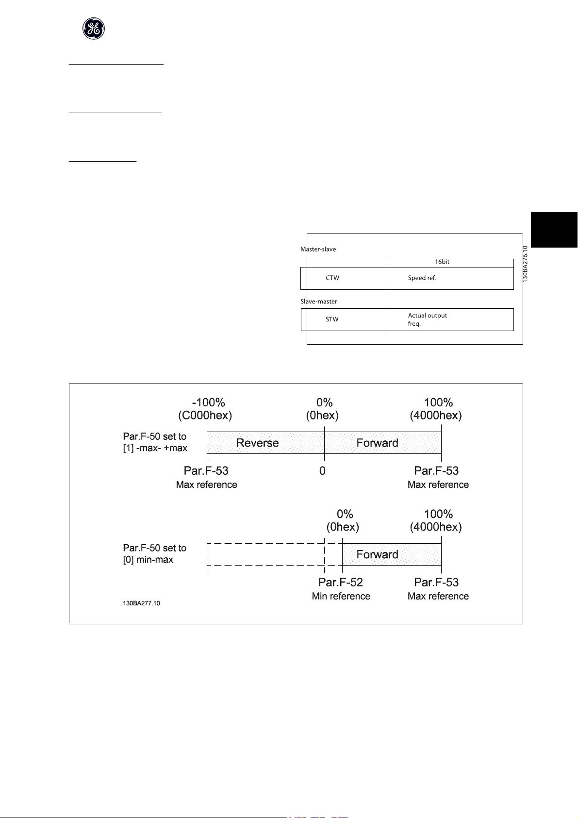
5.6.5 Bus Speed Reference Value
The speed reference value is transmitted to the frequency converter in a rel-
ative value in %.
The value is transmitted in the form of a 16-bit word; in integers (0-32767) the
value 16384 (4000 Hex) corresponds to 100%. Negative figures are formatted
by means of 2's complement.
The Actual Output Frequency (MAV) is scaled in the same way as the bus
reference.
The reference and MAV are scaled as follows:
5
DET-579A
41
Page 43

6
AF-60 LP™ Micro Drive Operating Instructions
42
DET-579A
Page 44

6 Parameter Overview
AF-60 LP™ Micro Drive Operating Instructions
6
DET-579A
43
Page 45

6
AF-60 LP™ Micro Drive Operating Instructions
[1] Analog input 53
[6] Digital input 29
2-XX Brakes
2-0XDC-Brake
2-00 DC Hold Current
0 - 150 % * 50 %
2-01 DC Brake Current
0 - 150 % * 50 %
2-02 DC Braking Time
0.0 - 60.0 s * 10.0 s
2-04 DC Brake Cut In Speed
0.0 - 400.0 Hz * 0.0 Hz
2-1X Brake Energy Funct.
2-10 Brake Function
*[0] Off
[1] Resistor brake
[2] AC brake
2-11 Brake Resistor (ohm)
5 - 5000 * 5
2-16 AC Brake, Max current
0 - 150 % * 100 %
2-17 Over-voltage Control
*[0] Disabled
[1] Enabled (not at stop)
[2] Enabled
2-2* Mechanical Brake
2-20 Release Brake Current
0.00 - 100.0 A * 0.00 A
2-22 Activate Brake Speed [Hz]
0.0 - 400.0 Hz * 0.0 Hz
3-XX Reference / Ramps
3-0X Reference Limits
3-00 Reference Range
*[0] Min - Max
[1] -Max - +Max
3-02 Minimum Reference
-4999 - 4999 * 0.000
3-03 Maximum Reference
-4999 - 4999 * 50.00
3-1X References
3-10 Preset Reference
-100.0 - 100.0 % * 0.00 %
3-11 Jog Speed [Hz]
0.0 - 400.0 Hz * 5.0 Hz
3-12 Catch up/slow Down Value
0.00 - 100.0 % * 0.00 %
1-33 Stator Leakage Reactance (X1)
[Ohm] * Dep. on motor data
Parameter Overwiev
1-XX Load/Motor
1-0X General Settings
1-35 Main Reactance (Xh)
[Ohm] * Dep. on motor data
1-5X Load Indep. Setting
1-50 Motor Magnetisation at 0 Speed
0 - 300 % * 100 %
1-52 Min Speed Norm. Magnet. [Hz]
1-00 Configuration Mode
*[0] Speed open loop
[3] Process
1-01 Motor Control Principle
[0] U/f
*[1] Adv.Vector Control
0.0 - 10.0 Hz * 0.0 Hz
1-03 Torque Characteristics
1-55 U/f Characteristic - U
0 - 999.9 V
*[0] Constant torque
[2] Energy Saving
1-56 U/f Characteristic - F
1-05 Local Mode Configuration
0 - 400 Hz
1-6X Load Depen. Setting
[0] Speed Open Loop
*[2] As config in param. 1-00
1-60 Low Speed Load Compensation
0 - 199 % * 100 %
1-2X Motor Data
1-20 Motor Power [kW] [HP]
1-61 High Speed Load Compensation
[1] 0.09 kW/0.12 HP
0 - 199 % * 100 %
1-62 Slip Compensation
-400 - 399 % * 100 %
1-63 Slip Compensation Time Constant
0.05 - 5.00 s * 0.10 s
1-7X Start Adjustments
1-71 Holding Time
0.0 - 10.0 s * 0.0 s
1-72 Start Function
[0] DC hold / delay time
[1] DC brake / delay time
*[2] Coast / delay time
1-73 Start Mode
*[0] Disabled
[1] Enable - Catch Spinning Load
1-8X Stop Adjustments
1-80 Function at Stop
*[0] Coast
[1] DC hold
1-82 Min Speed for Funct. at Stop [Hz]
0.0 - 20.0 Hz * 0.0 Hz
1-9XMotor Temperature
1-90 Motor Thermal Protection
*[0] No protection
[1] Termistor warning
[2] Thermistor trip
[3] Electronic Overload warning
[4] Electronic Overload trip
1-93 Thermistor Resource
*[0] None
[2] 0.12 kW/0.16 HP
[3] 0.18 kW/0.25 HP
[4] 0.25 kW/0.33 HP
[5] 0.37 kW/0.50 HP
[6] 0.55 kW/0.75 HP
[7] 0.75 kW/1.00 HP
[8] 1.10 kW/1.50 HP
[9] 1.50 kW/2.00 HP
[10] 2.20 kW/3.00 HP
[11] 3.00 kW/4.00 HP
[12] 3.70 kW/5.00 HP
[13] 4.00 kW/5.40 HP
[14] 5.50 kW/7.50 HP
[15] 7.50 kW/10.00 HP
[16] 11.00 kW/15.00 HP
[17] 15.00 kW/20.00 HP
[18] 18.50 kW/25.00 HP
[19] 22.00 kW/29.50 HP
[20] 30.00 kW/40.00 HP
1-22 Motor Voltage
50 - 999 V * 230 - 400 V
1-23 Motor Frequency
20 - 400 Hz * 60 Hz
1-24 Motor Current
0.01 - 100.00 A * Motortype dep.
1-25 Motor Nominal Speed
100 - 9999 rpm * Motortype dep.
1-29 Auto Tune
*[0] Off
[2] Enable Auto Tune
1-3X Adv. Motor Data
1-30 Stator Resistance (Rs)
[Ohm] * Dep. on motor data
44
0-XX Operation/Display
0-0X Basic Settings
0-03 Regional Settings
[0] International
*[1] US
0-04 Oper. State at Power-up (Hand)
[0] Resume
[1] Forced stop, ref = old
[2] Forced stop, ref = 0
0-1X Set-up Handling
0-10 Active Set-up
*[1] Setup 1
[2] Setup 2
[9] Multi Setup
0-11 Edit Set-up
*[1] Setup 1
[2] Setup 2
[9] Active Setup
0-12 Link Setups
[0] Not Linked
*[20] Linked
0-31 Custom Readout Min Scale
0.00 – 9999.00
*0.00
0-32 Custom Readout Max Scale
0.00 – 9999.00
*100.0
0-4X Keypad
0-40 [Hand] Key on Keypad
[0] Disabled
*[1] Enabled
0-41 [Off / Reset] Key on Keypad
[0] Disable All
*[1] Enable All
[2] Enable Reset Only
0-42 [Auto] Key on Keypad
[0] Disabled
*[1] Enabled
0-5X Copy/Save
0-50 Keypad Copy
*[0] No copy
[1] All to Keypad
[2] All from Keypad
[3] Size indep. from Keypad
0-51 Set-up Copy
*[0] No copy
[1] Copy from setup 1
[2] Copy from setup 2
[9] Copy from Factory setup
0-6X Password
0-60 (Main) Menu Password
0 - 999 * 0
DET-579A
Page 46

[25] Reverse
[26] Bus ok
[28] Brake,NoWarn
[29] Brake ready/NoFault
AF-60 LP™ Micro Drive Operating Instructions
[30] BrakeFault (IGBT)
[32] Mech.brake control
[36] Control word bit 11
[51] Local ref. active
[52] Remote ref. active
[53] No alarm
[54] Start cmd active
[55] Running reverse
[56] Drive in hand mode
[57] Drive in auto mode
[60-63] Comparator 0-3
[70-73] Logic rule 0-3
[81] Logic Controller digital output B
5-5X Pulse Input
5-55 Terminal 33 Low Frequency
20 - 4999 Hz * 20 Hz
5-56 Terminal 33 High Frequency
21 - 5000 Hz * 5000 Hz
5-57 Term. 33 Low Ref./Feedb. Value
-4999 - 4999 * 0.000
5-58 Term. 33 High Ref./Feedb. Value
-4999 - 4999 * 50.000
6-XX Analog In/Out
6-0X Analog I/O Mode
6-00 Live Zero Timeout Time
1 - 99 s * 10 s
6-01 Live Zero TimeoutFunction
*[0] Off
[1] Freeze output
[2] Stop
[3] Jogging
[4] Max speed
[5] Stop and trip
6-1X Analog Input 1
6-10 Terminal 53 Low Voltage
0.00 - 9.99 V * 0.07 V
6-11 Terminal 53 High Voltage
0.01 - 10.00 V * 10.00 V
6-12 Terminal 53 Low Current
0.00 - 19.99 mA * 0.14 mA
6
[16-18] Preset ref bit 0-2
[19] Freeze reference
)
1)
3-80 Jog Accel and Decel Time
0.05 - 3600 s * 3.00 s (10.00 s
[20] Freeze output
[21] Speed up
[22] Speed down
[23] Setup select bit 0
)
1)
3-81 Quick Stop Decel Time
0.05 - 3600 s * 3.00 s(10.00 s
4-XX Limits / Warnings
4-1X Motor Limits
[28] Catch up
[29] Slow down
4-10 Reverse Lock
[0] Reverse Lock
[34] Ramp bit 0
[60] Counter A (up)
[61] Counter A (down)
[62] Reset counter A
[63] Counter B (up)
[1] Reverse
*[2] Both
4-12 Motor Speed Low Limit [Hz]
0.0 - 400.0 Hz * 0.0 Hz
4-14 Motor Speed High Limit [Hz]
[64] Counter B (down)
[65] ResetCounter B
0.1 - 400.0 Hz * 65.0 Hz
4-16 Torque Limit Motor Mode
5-11 Terminal 19 Digital Input
0 - 400 % * 150 %
See par. 5-10. * [10] Reversing
5-12 Terminal 27 Digital Input
4-17 Torque Limit Generator Mode
0 - 400 % * 100 %
See par. 5-10. * [1] Reset
5-13 Terminal 29 Digital Input
See par. 5-10. * [14] Jog
5-15 Terminal 33 Digital Input
See par. 5-10. * [16] Preset ref bit 0
[26] Precise Stop Inverse
4-5X Adj. Warnings
4-50 Warning Current Low
0.00 - 100.00 A * 0.00 A
4-51 Warning Current High
0.00 - 100.00 A * 100.00 A
4-58 Missing Motor Phase Function
[27] Start, Precise Stop
[0] Off
[32] Pulse Input
5-4X Relays
*[1] On
4-6X Jump Frequencies
5-40 Function Relay
4-61 Jump Frequency From [Hz]
*[0] No opreation
[1] Control ready
0.0 - 400.0 Hz * 0.0 Hz
4-63 Jump FrequencyTo [Hz]
[2] Drive ready
[3] Drive ready, Remote
[4] Enable / No warning
0.0 - 400.0 Hz * 0.0 Hz
5-1X Digital Inputs
5-10 Terminal 18 Digital Input
[5] Drive running
[6] Running / No warning
[7] Run in range / No warning
[0] No function
[1] Reset
[2] Coast inverse
)
1)
[8] Run on ref / No warning
[9] Alarm
[10] Alarm or warning
[3] Coast and reset inv.
[4] Quick stop inverse
[5] DC-brake inv.
)
1)
[12] Out of current range
[13] Below current, low
[14] Above current, high
[6] Stop inv
*[8] Start
[9] Latched start
[21] Thermal warning
[22] Ready, No thermal warning
[23] Remote ready, No thermal warning
[24] Ready, Voltage ok
[10] Reversing
[11] Start reversing
[12] Enable start forward
[13] Enable start reverse
)
)
1)
1)
[14] Jog
3-42 Decel Time 1
3-14 Preset Relative Reference
-100.0 - 100.0 % * 0.00 %
3-15 Reference Resource 1
[0] No function
*[1] Analog Input 53
[2] Analog input 60
[8] Pulse input 33
[11] Local bus ref
[21] Keypad Potentiometer
3-16 Reference Resource 2
[0] No function
[1] Analog Input 53
*[2] Analog input 60
[8] Pulse input 33
*[11] Local bus ref
[21] Keypad Potentiometer
3-17 Reference Resource 3
[0] No function
[1] Analog Input 53
[2] Analog input 60
[8] Pulse input 33
*[11] Local bus ref
[21] Keypad Potentiometer
3-18 Relative Scaling Ref. Resource
*[0] No function
[1] Analog Input 53
[2] Analog input 60
[8] Pulse input 33
[11] Local bus ref
[21] Keypad Potentiometer
3-4X Accel/Decel 1
3-40 Accel/Decel 1 Pattern
*[0] Linear
[2] S-Shape
DET-579A
3-41 Accel Time 1
0.05 - 3600 s * 3.00 s (10.00 s
0.05 - 3600 s * 3.00 s (10.00 s
3-5X Accel/Decel 2
3-50 Accel/Decel 2 Pattern
*[0] Linear
[2] S-Shape
3-51 Accel Time 2
0.05 - 3600 s * 3.00 s (10.00 s
M4 and M5 only
3-8X Other Ramps
1)
3-52 Decel Time 2
0.05 - 3600 s * 3.00 s (10.00 s
45
Page 47

6
AF-60 LP™ Micro Drive Operating Instructions
8-9X Bus Jog / Feedback
8-94 Bus feedback 1
0x8000 - 0x7FFF * 0
13-XX Controller Logic
13-0X Logic Controller Settings
13-00 Logic Controller Mode
*[0] Off
[1] On
13-01 Start Event
[0] False
[1] True
[2] Running
[3] InRange
[4] OnReference
[7] OutOfCurrentRange
[8] BelowILow
[9] AboveIHigh
[16] ThermalWarning
[17] MainOutOfRange
[18] Reversing
[19] Warning
[20] Alarm_Trip
[21] Alarm_TripLock
[22-25] Comparator 0-3
[26-29] LogicRule0-3
[33] DigitalInput_18
[34] DigitalInput_19
[35] DigitalInput_27
[36] DigitalInput_29
[38] DigitalInput_33
*[39] StartCommand
[40] DriveStopped
13-02 Stop Event
See par. 13-01 * [40] DriveStopped
13-03 Reset Logic Controller
*[0] Do not reset
[1] Reset Logic Controller
13-1X Comparators
[4] Max. Speed
[5] Stop and trip
8-06 Reset Control Word Timeout
*[0] No Function
[1] Do reset
6-93 Terminal 42 Output Min Scale
0.00 - 200.0 % * 0.00 %
6-94 Terminal 42 Output Max Scale
0.00 - 200.0 % * 100.0 %
7-XX Controllers
8-3X GE Drive Port Settings
8-30 Protocol
*[0] GE Drive
[2] Modbus RTU
8-31 Address
1 - 247 * 1
8-32 GE Drive Port Baud Rate
[0] 2400 Baud
[1] 4800 Baud
*[2] 9600 Baud
[3] 19200 Baud
*[4] 38400 Baud
8-33 GE Drive Port Parity
*[0] Even Parity, 1 Stop Bit
[1] Odd Parity, 1 Stop Bit
[2] No Parity, 1 Stop Bit
[3] No Parity, 2 Stop Bits
8-35 Minimum Response Delay
0.001-0.5 * 0.010 s
8-36 Max Response Delay
0.100 - 10.00 s * 5.000 s
8-5X Digital/Bus
8-50 Coasting Select
[0] DigitalInput
[1] Bus
[2] LogicAnd
*[3] LogicOr
8-51 Quick Stop Select
See par. 8-50 * [3] LogicOr
8-52 DC Brake Select
See par. 8-50 * [3] LogicOr
8-53 Start Select
See par. 8-50 * [3] LogicOr
8-54 Reversing Select
See par. 8-50 * [3] LogicOr
8-55 Set-up Select
See par. 8-50 * [3] LogicOr
8-56 Preset Reference Select
See par. 8-50 * [3] LogicOr
7-2X Process Ctrl. Feedb
7-20 Process CL Feedback 1 Resource
*[0] NoFunction
[1] Analog Input 53
[2] Analog input 60
[8] PulseInput33
[11] LocalBusRef
7-3X Process PI
Ctrl. 7-30 Process PI Normal/ Inverse Ctrl
*[0] Normal
[1] Inverse
7-31 Process PI Anti Windup
[0] Disable
*[1] Enable
7-32 Process PI Start Speed
0.0 - 200.0 Hz * 0.0 Hz
7-33 Process PI Proportional Gain
0.00 - 10.00 * 0.01
7-34 Process PI Integral Time
0.10 - 9999 s * 9999 s
7-38 Process PI Feed Forward Factor
0 - 400 % * 0 %
7-39 On Reference Bandwidth
0 - 200 % * 5 %
8-XX Comm. and Options
8-0X General Settings
8-01 Control Site
*[0] Digital and ControlWord
[1] Digital only
[2] ControlWord only
8-02 Control Word Source
[0] None
*[1] GE Drive RS485
8-03 Control Word Timeout Time
0.1 - 6500 s * 1.0 s
8-04 Control Word Timeout Function
*[0] Off
[1] Freeze Output
[2] Stop
[3] Jogging
6-13 Terminal 53 High Current
0.01 - 20.00 mA * 20.00 mA
46
6-14 Term. 53 Low Ref./Feedb. Value
-4999 - 4999 * 0.000
6-15 Term. 53 High Ref./Feedb. Value
-4999 - 4999 * 50.000
6-16 Terminal 53 Filter Time Constant
0.01 - 10.00 s * 0.01 s
6-19 Terminal 53 mode
*[0] Voltage mode
[1] Current mode
6-2X Analog Input 2
6-22 Terminal 60 Low Current
0.00 - 19.99 mA * 0.14 mA
6-23 Terminal 60 High Current
0.01 - 20.00 mA * 20.00 mA
6-24 Term. 60 Low Ref./Feedb. Value
-4999 - 4999 * 0.000
6-25 Term. 60 High Ref./Feedb. Value
-4999 - 4999 * 50.00
6-26 Terminal 60 Filter Time Constant
0.01 - 10.00 s * 0.01 s
6-8X Keypad potentiometer
6-81 Keypad potm. Low Reference
-4999 - 4999 * 0.000
6-82 Keypad potm. High Reference
-4999 - 4999 * 50.00
6-9X Analog Output xx
6-90 Terminal 42 Mode
*[0] 0-20 mA
[1] 4-20 mA
[2] Digital Output
6-91 Terminal 42 Analog Output
*[0] No operation
[10] Output Frequency
[11] Reference
[12] Feedback
[13] Motor Current
[16] Power
[20] Bus Reference
6-92 Terminal 42 Digital Output
See par. 5-40
*[0] No Operation
[80] Logic Controller Digital Output A
DET-579A
Page 48

16-1X Motor Status
16-10 Power [kW]
16-11 Power [hp]
16-12 Motor Voltage [V]
16-13 Frequency [Hz]
AF-60 LP™ Micro Drive Operating Instructions
16-14 Motor Current [A]
16-15 Frequency [%]
16-18 Motor Thermal [%]
16-3X Drive Status
16-30 DC Link Voltage
16-34 Heatsink Temp.
16-35 Inverter Thermal
16-36 Drive Nominal current
16-37 Drive Maximum Current
16-38 Logic Controller State
16-5X Ref. / Feedb.
16-50 External Reference
16-51 Pulse Reference
16-52 Feedback [Unit]
16-6X Inputs / Outputs
16-60 Digital Input 18,19,27,33
0 - 1111
16-61 Digital Input 29
0 - 1
16-62 Analog Input 53 (volt)
16-63 Analog Input 53 (current)
16-64 Analog Input 60
16-65 Analog Output 42 [mA]
16-68 Pulse Input [Hz]
16-71 Relay Output [bin]
16-72 Counter A
16-73 Counter B
16-8X Fieldbus / GE Drive Port
16-86 GE Drive Port REF 1
0x8000 - 0x7FFFF
16-9X Diagnosis Readouts
16-90 Alarm Word
0 - 0XFFFFFFFF
16-92 Warning Word
0 - 0XFFFFFFFF
16-94 Ext. Status Word
0 - 0XFFFFFFFF18-XX Extended Motor Data
18-8X Motor Resistors
18-80 Stator Resistance (High resolution)
0.000 - 99.990 ohm * 0.000 ohm
18-81 Stator Leakage Reactance(High resolution)
0.000 - 99.990 ohm * 0.000 ohm
6
14-22 Restore Factory Settings
[1] NoAction
*[0] Normal Operation
[2] Restore Factory Settings
[2] SelectSetup1
[3] SelectSetup2
14-26 Action At Drive Fault
*[0] Trip
[10-17] SelectPresetRef0-7
[18] Select Accel/Decel 1.
[1] Warning
14-4X Energy Savings
14-41 Energy Savings Minimum Magnetisation
[19] Select Accel/Decel 2.
[22] Run
[23] RunReverse
40 - 75 % * 66 %
15-XX Drive Information
[24] Stop
[25] Qstop
15-0X Operating Data
15-00 Operating Days
15-01 Running Hours
[26] DCstop
[27] Coast
[28] FreezeOutput
15-02 kWh Counter
15-03 Power Ups
15-04 Over Temps
[29] StartTimer0
[30] StartTimer1
[31] StartTimer2
15-05 Over Volts
15-06 Reset kWh Counter
[32] Set Digital Output A Low
[33] Set Digital Output B Low
*[0] Do not reset
[1] Reset counter
15-07 Reset Running Hours Counter
*[0] Do not reset
[38] Set Digital Output A High
[39] Set Digital Output B High
[60] ResetCounterA
[61] ResetCounterB
[1] Reset counter
15-3X Fault Log
14-XX Special Functions
14-0X Carrier Frequency
15-30 Fault Log: Error Code
15-4X Drive Identification
15-40 GE Drive Type
15-41 Power Section
15-42 Voltage
15-43 Software Version
15-46 Frequency Converter Order. No
15-48 Keypad Id No
15-51 Frequency Converter Serial No
16-XX Data Readouts
16-0X General Status
16-00 Control Word
0 - 0XFFFF
16-01 Reference [Unit]
-4999 - 4999
16-02 Reference %
-200.0 - 200.0 %
16-03 Status Word
0 - 0XFFFF
16-05 Main Actual Value [%]
-200.0 - 200.0 %
16-09 Custom Readout
Dep. on par. 0-31, 0-32 and 4-14
14-01 Motor Noise
(Carrier Frequency)
[0] 2 kHz
*[1] 4 kHz
[2] 8 kHz
[4] 16 kHz
14-03 Overmodulation
[0] Off
*[1] On
14-1X Mains monitoring
14-12 Function at mains imbalance
*[0] Trip
[1] Warning
[2] Disabled
14-2X Trip Reset
14-20 Reset Mode
*[0] Manual reset
[1-9] AutoReset 1-9
[10] AutoReset 10
[11] AutoReset 15
[12] AutoReset 20
[13] Infinite auto reset
14-21 Automatic Restart Time
0 - 600 s * 10 s
13-10 Comparator Operand
*[0] Disabled
[1] Reference
[2] Feedback
[3] MotorSpeed
[4] MotorCurrent
[6] MotorPower
[7] MotorVoltage
[8] DCLinkVoltage
[12] AnalogInput53
[13] AnalogInput60
[18] PulseInput33
[20] AlarmNumber
[30] CounterA
[31] CounterB
13-11 Comparator Operator
[0] Less Than
*[1] Approximately equals
[2] Greater Than
13-12 Comparator Value
-9999 - 9999 * 0.0
13-2X Timers
13-20 LC Controller Timer
0.0 - 3600 s * 0.0 s
13-4X Logic Rules
13-40 Logic Rule Boolean 1
See par. 13-01 * [0] False
[30] - [32] LC Time-out 0-2
13-41 Logic Rule Operator 1
*[0] Disabled
[1] And
[2] Or
[3] And not
[4] Or not
[5] Not and
[6] Not or
[7] Not and not
[8] Not or not
13-42 Logic Rule Boolean 2
See par. 13-40
13-43 Logic Rule Operator 2
See par. 13-41 * [0] Disabled
13-44 Logic Rule Boolean 3
See par. 13-40
13-5X States
13-51 LC Controller Event
See par. 13-40
13-52 LC Controller Action
*[0] Disabled
DET-579A
47
Page 49

AF-60 LP™ Micro Drive Operating Instructions
6.2.1 Conversion Index
The various attributes of each parameter are displayed in the section Factory Settings. Parameter values are transferred as whole numbers only. Conversion
factors are therefore used to transfer decimals according to the table below.
Example:
Par. 1-24 Motor Current has a conversion index of -2 (i.e. conversion factor of 0.01 according to the table below). To set the parameter to 2.25 A, transfer the value
225 via Modbus. The Conversion Factor of 0.01 means that the value transferred is multiplied by 0.01 in the drive. The vale 225 transferred on the bus is thus
perceived as 2.25 A in the drive.
Conversion index Conversion factor
2 10
1100
0 1
-1 0.1
-2 0.01
-3 0.001
6
-4 0.0001
-5 0.00001
Table 6.1: Conversion table
6.2.2 Change during operation
“TRUE” means that the parameter can be changed while the frequency converter is in operation and “FALSE” means that the frequency converter must be stopped
before a change can be made.
6.2.3 2-Set-up
“All set-up”: The parameter can be set individually in each of the two set-ups, i.e. one single parameter can have two different data values.
”1 set-up”: Data value will be the same in both set-ups.
6.2.4 Type
Data Type Description Type
2Integer 8Int8
3 Integer 16 Int16
4 Integer 32 Int32
5 Unsigned 8 Uint8
6 Unsigned 16 Uint16
7 Unsigned 32 Uint32
9 Visible string VisibleString
48
DET-579A
Page 50
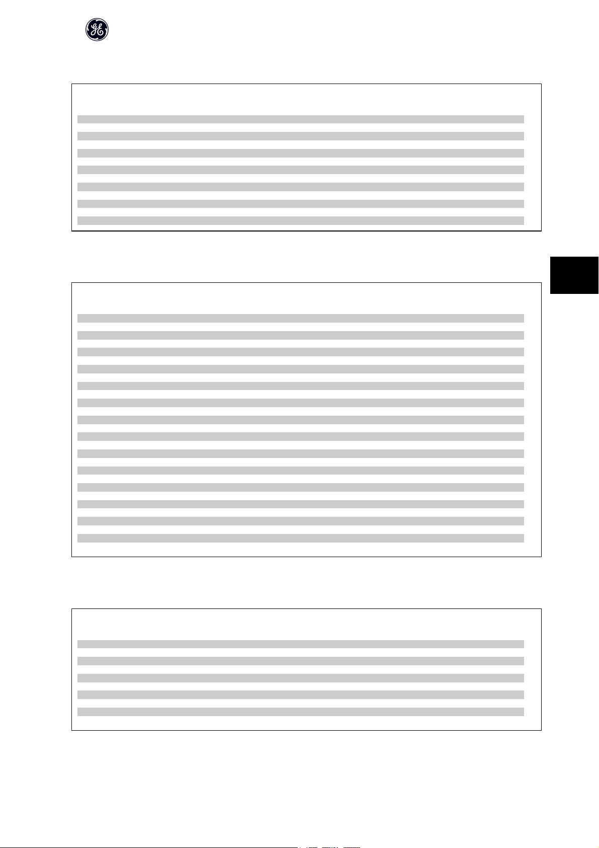
6.2.5 0-** Operation/Display
AF-60 LP™ Micro Drive Operating Instructions
Parameter
Number
0 - 03 Regional Settings [1] US 1 set-up FALSE - Uint8
0 - 04 Operating State at Power-up (Hand) [1] Forced stop ref=old All set-ups TRUE - Uint8
0 - 10 Active Set-up [1] Set-up 1 1 set-up TRUE - Uint8
0 - 11 Edit Set-up [1] Set-up 1 1 set-up TRUE - Uint8
0 - 12 Link Setups [20] Linked All set-ups FALSE - Uint8
0 - 31 Custom Readout Min Scale 0 1 set-up TRUE -2 Int32
0 - 32 Custom Readout Max Scale 0 1 set-up TRUE -2 Int32
0 - 40 [Hand ] Key on Keypad [1] Enabled All set-ups TRUE - Uint8
0 - 41 [Off / Reset] Key on Keypad [1] Enable All All set-ups TRUE - Uint8
0 - 42 [Auto ] Key on Keypad [1] Enabled All set-ups TRUE - Uint8
0 - 50 Keypad Copy [0] No copy 1 set-up FALSE - Uint8
0 - 51 Set-up Copy [0] No copy 1 set-up FALSE - Uint8
0 - 60 Main Menu Password 0 1 set-up TRUE 0 Uint16
Parameter Description Default Value 2 Setup Change During
Operation
Conver-
sion
Index
6.2.6 1-** Load/Motor
Parameter
Number
1 - 00 Configuration Mode [0] Speed open loop All set-ups TRUE - Uint8
1 - 01 Motor Control Principle [1] Adv. Vector Control All set-ups FALSE - Uint8
1 - 03 Torque Characteristics [0] Constant torque All set-ups TRUE - Uint8
1 - 05 Hand Mode Configuration [2] As mode par 1-00 All set-ups TRUE - Uint8
1 - 20 Motor Power All set-ups FALSE - Uint8
1 - 22 Motor Voltage All set-ups FALSE 0 Uint16
1 - 23 Motor Frequency All set-ups FALSE 0 Uint16
1 - 24 Motor Current All set-ups FALSE -2 Uint16
1 - 25 Motor Nominal Speed All set-ups FALSE 0 Uint16
1 - 29 Auto Tune [0] Off 1 set-up FALSE - Uint8
1 - 30 Stator Resistance (Rs) All set-ups FALSE -2 Uint16
1 - 33 Stator Leakage Reactance (X1) All set-ups FALSE -2 Uint32
1 - 35 Main Reactance (Xh) All set-ups FALSE -2 Uint32
1 - 50 Motor Magnetisation at Zero Speed 100% All set-ups TRUE 0 Uint16
1 - 52 Min Speed Normal Magnetising [Hz] 0 Hz All set-ups TRUE -1 Uint16
1 - 55 U/f Characteristic - U All set-ups TRUE 0 Uint16
1 - 56 U/f Characteristic - F All set-ups TRUE 0 Uint16
1 - 60 Low Speed Load Compensation 100% All set-ups TRUE 0 Uint16
1 - 61 High Speed Load Compensation 100% All set-ups TRUE 0 Uint16
1 - 62 Slip Compensation 100% All set-ups TRUE 0 Int16
1 - 63 Slip Compensation Time Constant 0.1 s All set-ups TRUE -2 Uint16
1 - 71 Holding Time 0 s All set-ups TRUE -1 Uint8
1 - 72 Start Function [2] Coast/delay time All set-ups TRUE - Uint8
1 - 73 Start Mode [0] Disabled All set-ups FALSE - Uint8
1 - 80 Function at Stop [0] Coast All set-ups TRUE - Uint8
1 - 82 Min Speed for Function at Stop [Hz] 0 Hz All set-ups TRUE -1 Uint16
1 - 90 Motor Thermal Protection [0] No protection All set-ups TRUE - Uint8
1 - 93 Thermistor Resource [0] None All set-ups FALSE - Uint8
Parameter Description Default Value 2 Setup Change During
Operation
Conver-
sion
Index
Type
6
Type
6.2.7 2-** Brakes
Parameter
Number
2 - 00 DC Hold Current 50% All set-ups TRUE 0 Uint16
2 - 01 DC Brake Current 50% All set-ups TRUE 0 Uint16
2 - 02 DC Braking Time 10 s All set-ups TRUE -1 Uint16
2 - 04 DC Brake Cut In Speed 0 Hz All set-ups TRUE -1 Uint16
2 - 10 Brake Function [0] Off All set-ups TRUE - Uint8
2 - 11 Brake Resistor (ohm) All set-ups TRUE 0 Uint16
2 - 16 AC Brake, Max current 100% All set-ups TRUE 0 Uint16
2 - 17 Over-voltage Control [0] Disabled All set-ups TRUE - Uint8
2 - 20 Release Brake Current 0 A All set-ups TRUE -2 Uint32
2 - 22 Activate Brake Speed [Hz] 0 Hz All set-ups TRUE -1 Uint16
Parameter Description Default Value 2 Setup Change During
Operation
Conver-
sion
Index
DET-579A
Type
49
Page 51

6.2.8 3-** Reference/Ramps
AF-60 LP™ Micro Drive Operating Instructions
6
Parameter
Number
3 - 00 Reference Range [0] Min - Max All set-ups TRUE - Uint8
3 - 02 Minimum Reference 0 All set-ups TRUE -3 Int32
3 - 03 Maximum Reference 50 All set-ups TRUE -3 Int32
3 - 10 Preset Reference 0% All set-ups TRUE -2 Int16
3 - 11 Jog Speed [Hz] 5 Hz All set-ups TRUE -1 Uint16
3 - 12 Catch up/slow Down Value 0% All set-ups TRUE -2 Int16
3 - 14 Preset Relative Reference 0% All set-ups TRUE -2 Int16
3 - 15 Reference Resource 1 [1] Analog in 53 All set-ups TRUE - Uint8
3 - 16 Reference Resource 2 [2] Analog in 60 All set-ups TRUE - Uint8
3 - 17 Reference Resource 3 [11] Local bus reference All set-ups TRUE - Uint8
3 - 18
3 - 40 Accel/Decel 1 Pattern [0] Linear All set-ups TRUE - Uint8
3 - 41 Accel Time 1 3 s All set-ups TRUE -2 Uint32
3 - 42 Decel Time 1 3 s All set-ups TRUE -2 Uint32
3 - 50 Accel/Decel 2 Pattern [0] Linear All set-ups TRUE - Uint8
3 - 51 Accel Time 2 3 s All set-ups TRUE -2 Uint32
3 - 52 Decel Time 2 3 s All set-ups TRUE -2 Uint32
3 - 80 Jog Accel/Decel Time 3 s All set-ups TRUE -2 Uint32
3 - 81 Quick Stop Ramp Time 3 s 1 set-up TRUE -2 Uint32
Parameter Description Default Value 2 Setup Change During
Relative Scaling Reference Resource
6.2.9 4-** Limits/Warnings
Parameter
Number
4 - 10 Reverse Lock [2] Both directions All set-ups FALSE - Uint8
4 - 12 Motor Speed Low Limit [Hz] 0 Hz All set-ups FALSE -1 Uint16
4 - 14 Motor Speed High Limit [Hz] 65 Hz All set-ups FALSE -1 Uint16
4 - 16 Torque Limit Motor Mode 150% All set-ups TRUE 0 Uint16
4 - 17 Torque Limit Generator Mode 100% All set-ups TRUE 0 Uint16
4 - 50 Warning Current Low 0 A All set-ups TRUE -2 Uint32
4 - 51 Warning Current High 26 A All set-ups TRUE -2 Uint32
4 - 58 Missing Motor Phase Function [1] On All set-ups FALSE - Uint8
4 - 61 Jump Frequency From [Hz] 0 Hz All set-ups TRUE -1 Uint16
4 - 63 Jump Frequency To [Hz] 0 Hz All set-ups TRUE -1 Uint16
Parameter Description Default Value 2 Setup Change During
Operation
[0] No function All set-ups TRUE - Uint8
Operation
Conver-
sion
Index
Conver-
sion
Index
Type
Type
6.2.10 5-** Digital In/Out
Parameter
Number
5 - 10 Terminal 18 Digital Input [8] Start All set-ups TRUE - Uint8
5 - 11 Terminal 19 Digital Input [10] Reversing All set-ups TRUE - Uint8
5 - 12 Terminal 27 Digital Input [1] Reset All set-ups TRUE - Uint8
5 - 13 Terminal 29 Digital Input [14] Jog All set-ups TRUE - Uint8
5 - 15 Terminal 33 Digital Input [16] Preset ref bit 0 All set-ups TRUE - Uint8
5 - 40 Function Relay [0] No operation All set-ups TRUE - Uint8
5 - 55 Terminal 33 Low Frequency 20 Hz All set-ups TRUE 0 Uint16
5 - 56 Terminal 33 High Frequency 5000 Hz All set-ups TRUE 0 Uint16
5 - 57 Terminal 33 Low Ref./Feedb. Value 0 All set-ups TRUE -3 Int32
5 - 58 Terminal 33 High Ref./Feedb. Value 50 All set-ups TRUE -3 Int32
Parameter Description Default Value 2 Setup Change During
Operation
Conver-
sion
Index
Type
50
DET-579A
Page 52
6.2.11 6-** Analog In/Out
AF-60 LP™ Micro Drive Operating Instructions
Parameter
Number
6 - 00 Live Zero Timeout Time 10 s All set-ups TRUE 0 Uint8
6 - 01 Live Zero TimeoutFunction [0] Off All set-ups TRUE - Uint8
6 - 10 Terminal 53 Low Voltage 0.07 V All set-ups TRUE -2 Uint16
6 - 11 Terminal 53 High Voltage 10 V All set-ups TRUE -2 Uint16
6 - 12 Terminal 53 Low Current 0.14 mA All set-ups TRUE -2 Uint16
6 - 13 Terminal 53 High Current 20 mA All set-ups TRUE -2 Uint16
6 - 14 Terminal 53 Low Ref./Feedb. Value 0 All set-ups TRUE -3 Int32
6 - 15 Terminal 53 High Ref./Feedb. Value 50 All set-ups TRUE -3 Int32
6 - 16 Terminal 53 Filter Time Constant 0.01 s All set-ups TRUE -2 Uint16
6 - 19 Terminal 53 mode [0] Voltage mode 1 set-up TRUE - Uint8
6 - 22 Terminal 60 Low Current 0.14 mA All set-ups TRUE -2 Uint16
6 - 23 Terminal 60 High Current 20 mA All set-ups TRUE -2 Uint16
6 - 24 Terminal 60 Low Ref./Feedb. Value 0 All set-ups TRUE -3 Int32
6 - 25 Terminal 60 High Ref./Feedb. Value 50 All set-ups TRUE -3 Int32
6 - 26 Terminal 60 Filter Time Constant 0.01 s All set-ups TRUE -2 Uint16
6 - 81 Keypad potentiometer Low Ref. 0 All set-ups TRUE -3 Int32
6 - 82 Keypad potentiometer High Ref. 50 All set-ups TRUE -3 Int32
6 - 90 Terminal 42 Mode [0] 0-20 mA All set-ups TRUE - Uint8
6 - 91 Terminal 42 Analog Output [0] No operation All set-ups TRUE - Uint8
6 - 92 Terminal 42 Digital Output [0] No operation All set-ups TRUE - Uint8
6 - 93 Terminal 42 Output Min Scale 0% All set-ups TRUE -2 Uint16
6 - 94 Terminal 42 Output Max Scale 100% All set-ups TRUE -2 Uint16
Parameter Description Default Value 2 Setup Change During
Operation
Conver-
sion
Index
6.2.12 7-** Controllers
Parameter
Number
7 - 20 Process CL Feedback 1 Resource [0] No function All set-ups TRUE - Uint8
7 - 30 Process PI Normal/ Inverse Control [0] Normal All set-ups TRUE - Uint8
7 - 31 Process PI Anti Windup [1] Enabled All set-ups TRUE - Uint8
7 - 32 Process PI Start Speed 0 Hz All set-ups TRUE -1 Uint16
7 - 33 Process PI Proportional Gain 0.01 All set-ups TRUE -2 Uint16
7 - 34 Process PI Integral Time 9999 s All set-ups TRUE -2 Uint32
7 - 38 Process PI Feed Forward Factor 0% All set-ups TRUE 0 Uint16
7 - 39 On Reference Bandwidth 5% All set-ups TRUE 0 Uint8
Parameter Description Default Value 2 Setup Change During
Operation
Conver-
sion
Index
Type
6
Type
6.2.13 8-** Comm. and Options
Parameter
Number
8 - 01 Control Site [0] Digital and ctrl.word All set-ups TRUE - Uint8
8 - 02 Control Word Source [1] GE Drive RS485 All set-ups TRUE - Uint8
8 - 03 Control Word Timeout Time 1 s 1 set-up TRUE -1 Uint16
8 - 04 Control Word Timeout Function [0] Off 1 set-up TRUE - Uint8
8 - 06 Reset Control Word Timeout [0] No function 1 set-up TRUE - Uint8
8 - 30 Protocol [0] GE Drive 1 set-up TRUE 0 Uint8
8 - 31 Address 1 1 set-up TRUE 0 Uint8
8 - 32 GE Drive Port Baud Rate [2] 9600 Baud 1 set-up TRUE - Uint8
8 - 33 GE Drive Port Parity [0] Even Parity 1 Stop Bit 1 set-up TRUE - Uint8
8 - 35 Minimum Response Delay 0.01 s 1 set-up TRUE -3 Uint16
8 - 36 Max Response Delay 5 s 1 set-up TRUE -3 Uint16
8 - 50 Coasting Select [3] Logic OR All set-ups TRUE - Uint8
8 - 51 Quick Stop Select [3] Logic OR All set-ups TRUE - Uint8
8 - 52 DC Brake Select [3] Logic OR All set-ups TRUE - Uint8
8 - 53 Start Select [3] Logic OR All set-ups TRUE - Uint8
8 - 54 Reversing Select [3] Logic OR All set-ups TRUE - Uint8
8 - 55 Set-up Select [3] Logic OR All set-ups TRUE - Uint8
8 - 56 Preset Reference Select [3] Logic OR All set-ups TRUE - Uint8
8 - 94 Bus feedback 1 0 All set-ups TRUE 0 Int16
Parameter Description Default Value 2 Setup Change During
Operation
Conver-
sion
Index
Type
DET-579A
51
Page 53

6.2.14 13-** Logic Controller
AF-60 LP™ Micro Drive Operating Instructions
Parameter
Number
13 - 00 Logic Controller Mode [0] Off 1 set-up TRUE - Uint8
13 - 01 Start Event [39] Start command 1 set-up TRUE - Uint8
13 - 02 Stop Event [40] Drive stopped 1 set-up TRUE - Uint8
13 - 03 Reset Logic Controller [0] Do not reset 1 set-up TRUE - Uint8
13 - 10 Comparator Operand [0] Disabled 1 set-up TRUE - Uint8
13 - 11 Comparator Operator [1] ApproxEqual 1 set-up TRUE - Uint8
13 - 12 Comparator Value 0 1 set-up TRUE -1 Int32
13 - 20 Logic Controller Controller Timer 0 s 1 set-up TRUE -1 Uint32
13 - 40 Logic Rule Boolean 1 [0] False 1 set-up TRUE - Uint8
13 - 41 Logic Rule Operator 1 [0] Disabled 1 set-up TRUE - Uint8
13 - 42 Logic Rule Boolean 2 [0] False 1 set-up TRUE - Uint8
13 - 43 Logic Rule Operator 2 [0] Disabled 1 set-up TRUE - Uint8
13 - 44 Logic Rule Boolean 3 [0] False 1 set-up TRUE - Uint8
13 - 51 Logic Controller Event [0] False 1 set-up TRUE - Uint8
13 - 52 Logic Controller Action [0] Disabled 1 set-up TRUE - Uint8
Parameter Description Default Value 2 Setup Change During
6
6.2.15 14-** Special Functions
Parameter
Number
14 - 01 Motor Noise (Carrier Freq.) [1] 4.0 kHz All set-ups TRUE - Uint8
14 - 03 Overmodulation [1] On All set-ups FALSE - Uint8
14 - 12 Function at Mains Imbalance [0] Trip All set-ups TRUE - Uint8
14 - 20 Reset Mode [0] Manual reset All set-ups TRUE - Uint8
14 - 21 Automatic Restart Time 10 s All set-ups TRUE 0 Uint16
14 - 22 Restore Factory Settings [0] Normal operation 1 set-up TRUE - Uint8
14 - 26 Action At Inverter Fault [0] Trip All set-ups TRUE - Uint8
14 - 41
Parameter Description Default Value 2 Setup Change During
Energy Savings Minimum Magnetisation 66 % All set-ups TRUE 0 Uint8
Operation
Operation
Conver-
sion
Index
Conver-
sion
Index
Type
Type
6.2.16 15-** Drive Information
Parameter
Number
15 - 00 Operating Time 0 1 set-up TRUE 0 Uint32
15 - 01 Running Hours 0 1 set-up TRUE 0 Uint32
15 - 02 kWh Counter 0 1 set-up TRUE 0 Uint32
15 - 03 Power Up's 0 1 set-up TRUE 0 Uint32
15 - 04 Over Temp's 0 1 set-up TRUE 0 Uint16
15 - 05 Over Volt's 0 1 set-up TRUE 0 Uint16
15 - 06 Reset kWh Counter [0] Do not reset 1 set-up TRUE - Uint8
15 - 07 Reset Running Hours Counter [0] Do not reset 1 set-up TRUE - Uint8
15 - 30 Fault Log: Error Code 0 1 set-up TRUE 0 Uint8
15 - 40 GE Drive Type 1 set-up FALSE 0
15 - 41 Power Section 1 set-up FALSE 0
15 - 42 Voltage 1 set-up FALSE 0
15 - 43 SW ID Control Card 1 set-up FALSE 0
15 - 46 Frequency Converter Ordering No 1 set-up FALSE 0
15 - 48 Keypad Id No 1 set-up FALSE 0
15 - 51 Frequency Converter Serial Number 1 set-up FALSE 0
Parameter Description Default Value 2 Setup Change During
Operation
Conver-
sion
Index
Type
Visible-
String
Visible-
String
Visible-
String
Visible-
String
Visible-
String
Visible-
String
Visible-
String
52
DET-579A
Page 54

6.2.17 16-** Data Readouts
AF-60 LP™ Micro Drive Operating Instructions
Parameter
Number
16 - 00 Control Word 0 1 set-up TRUE 0 Uint16
16 - 01 Reference [Unit] 0 1 set-up TRUE -3 Int32
16 - 02 Reference % 0 1 set-up TRUE -1 Int16
16 - 03 Status Word 0 1 set-up TRUE 0 Uint16
16 - 05 Main Actual Value [%] 0 1 set-up TRUE -2 Int16
16 - 09 Custom Readout 0 1 set-up TRUE -2 Int32
16 - 10 Power [kW] 0 1 set-up TRUE -3 Uint16
16 - 11 Power [hp] 0 1 set-up TRUE -3 Uint16
16 - 12 Motor Voltage 0 1 set-up TRUE 0 Uint16
16 - 13 Frequency 0 1 set-up TRUE -1 Uint16
16 - 14 Motor Current 0 1 set-up TRUE -2 Uint16
16 - 15 Frequency [%] 0 1 set-up TRUE -1 Uint16
16 - 18 Motor Thermal 0 1 set-up TRUE 0 Uint8
16 - 30 DC Link Voltage 0 1 set-up TRUE 0 Uint16
16 - 34 Heatsink Temp. 0 1 set-up TRUE 0 Uint8
16 - 35 Inverter Thermal 0 1 set-up TRUE 0 Uint8
16 - 36 Inv. Nom. Current 0 1 set-up TRUE -2 Uint16
16 - 37 Inv. Max. Current 0 1 set-up TRUE -2 Uint16
16 - 38 Logic Controller State 0 1 set-up TRUE 0 Uint8
16 - 50 External Reference 0 1 set-up TRUE -1 Int16
16 - 51 Pulse Reference 0 1 set-up TRUE -1 Int16
16 - 52 Feedback [Unit] 0 1 set-up TRUE -3 Int32
16 - 60 Digital input 18,19,27,33 0 1 set-up TRUE 0 Uint16
16 - 61 Digital input 29 0 1 set-up TRUE 0 Uint8
16 - 62 Analog Input 53 (V) 0 1 set-up TRUE -2 Uint16
16 - 63 Analog Input 53 (mA) 0 1 set-up TRUE -2 Uint16
16 - 64 Analog Input 60 0 1 set-up TRUE -2 Uint16
16 - 65 Analog Output 42 [mA] 0 1 set-up TRUE -2 Uint16
16 - 68 Pulse input 33 20 1 set-up TRUE 0 Uint16
16 - 71 Relay Output [bin] 0 1 set-up TRUE 0 Uint8
16 - 72 Counter A 0 1 set-up TRUE 0 Int16
16 - 73 Counter B 0 1 set-up TRUE 0 Int16
16 - 86 GE Drive Port REF 1 0 1 set-up TRUE 0 Int16
16 - 90 Alarm Word 0 1 set-up TRUE 0 Uint32
16 - 92 Warning Word 0 1 set-up TRUE 0 Uint32
16 - 94 Ext. Status Word 0 1 set-up TRUE 0 Uint32
Parameter Description Default Value 2 Setup Change During
Operation
Conver-
sion
Index
Type
6
DET-579A
53
Page 55

7
AF-60 LP™ Micro Drive Operating Instructions
54
DET-579A
Page 56

7 Troubleshooting
AF-60 LP™ Micro Drive Operating Instructions
7
DET-579A
55
Page 57

7
AF-60 LP™ Micro Drive Operating Instructions
X X X Missing phase on supply side, or too high voltage imbalance. Check supply voltage.
1)
the Keypad.
in software versions.
X Wrong setting for motor voltage and/or motor current.
X X Intermediate circuit voltage exceeds limit.
X X Intermediate circuit voltage drops below “voltage warning low” limit.
1)
1)
X Motor current is too low. Check settings.
nom
and I
nom
nom
X No communication between Keypad and frequency converter
No. Description Warning Alarm Trip Lock Error Cause of Problem
56
Mains phase loss
DC under voltage
DC over voltage
2 Live zero error X X Signal on terminal 53 or 60 is less than 50% of value set in par. 6-10, 6-12 and 6-22.
7
9 Driveoverloaded X X More than 100% load for too long.
11 Motor thermistor over temperature X X Thermistor or thermistor connection is disconnected.
13 Over Current X X X Drive current limit is exceeded.
16 Short Circuit X X Short-circuit in motor or on motor terminals.
25 Brake resistor short-circuited X X Brake resistor is short-circuited, thus brake function is disconnected.
28 Brake check X Brake resistor is not connected/working
30 Motor phase U missing X X Motor phase U is missing. Check the phase.
32 Motor phase W missing X X Motor phase W is missing. Check the phase.
40 Earth fault (Desat) X X
51 Auto Tune check U
4
8
10 Motor Electronic Overload over temperature X X Motor is too hot due to more than 100% load for too long.
12 Torque limit X Torque exceeds value set in either par. 4-16 or 4-17.
14 Earth fault X X Discharge from output phases to ground.
17 Control word timeout X X No communication to frequency converter.
27 Brake chopper short-circuited X X Brake transistor is short-circuited, thus brake function is disconnected.
29 Power board over temp X X X Heat-sink cut-out temperature has been reached.
31 Motor phase V missing X X Motor phase V is missing. Check the phase.
38 Internal fault X X Contact local GE supplier.
47 Control Voltage Fault X X 24 V DC may be overloaded.
59 Current limit X Drive overload.
52 Auto Tune low I
80 Drive restored to Factory Settings X All parameter settings are restored to factory default settings.
63 Mechanical Brake Low X Actual motor current has not exceeded “release brake” current within “start delay” time window.
84 The connection between drive and Keypad is
DET-579A
lost
85 Button disabled X See parameter group 0-4* Keypad
86 Copy fail X An error occurred while copying from frequency converter to Keypad or vice versa.
87 Keypad data invalid X Occurs when copying from Keypad if the Keypad contains erroneous data - or if no data was uploaded to
88 Keypad data not compatible X Occurs when copying from Keypad if data are moved between frequency converters with major differences
89 Parameter read only X Occurs when trying to write to a read-only parameter.
91 Parameter value is not valid in this mode X Occurs when trying to write an illegal value to a parameter.
90 Parameter database busy X Keypad and RS485 connection are trying to update parameters simultaneously.
92 Parameter value exceeds the min/max limits X Occurs when trying to set a value outside the range.
These faults may be caused by mains distortions. Installing GE Line Filter may rectify this problem.
nw run Not While RUNning X Parameter can only be changed when the motor is stopped.
Table 7.1: Warnings and AlarmsCode list
1)
Err. A wrong password was entered X Occurs when using a wrong password for changing a password-protected parameter.
Page 58

AF-60 LP™ Micro Drive Operating Instructions
7.1.1 Alarm, Warning and Extended Status Word
Par 1690 Par 1692 Par 1694
Bit Hex Dec AlarmWord WarningWord ExtendedStatusWord
01 1 Brake check Ramping
1 2 2 Pwr.card temp Pwr.card temp
2 4 4 Earth Fault Start CW/CCW
3 8 8 Slow down
4 10 16 Ctrl.word TO Ctrl.word TO Catch up
5 20 32 Over Current Over Current
640 64 Torque limit
7 80 128 Motor Thermistor Over Motor Thermistor Over Output current high
8 100 256 Electronic Overload Over Electronic Overload Over Output current low
9 200 512 Inverter overload Inverter overload
10 400 1024 DC under volt DC under volt
11 800 2048 DC over volt DC over volt
12 1000 4096 Short Circuit
13 2000 8192 Braking
14 4000 16384 Mains ph. loss Mains ph. loss
15 8000 32768 "Auto Tune Not OK" OVC active
16 10000 65536 Live zero error Live zero error AC brake
17 20000 131072 Internal fault
18 40000 262144
19 80000 524288 U phase loss
20 100000 1048576 V phase loss
21 200000 2097152 W phase loss
22 400000 4194304
23 800000 8388608 Control Voltage Fault
24 1000000 16777216
25 2000000 33554432 Current limit
26 4000000 67108864 Brake resistor shortcircuit
27 8000000 134217728 Brake IGBT shortcircuit
28 10000000 268435456 MotorPhaseMissing
29 20000000 536870912 Drive restored
30 40000000 1073741824 Undefined
31 80000000 2147483648 Mech. brake low DatabaseBusy
7
DET-579A
57
Page 59

AF-60 LP™ Micro Drive Operating Instructions
8
58
DET-579A
Page 60

AF-60 LP™ Micro Drive Operating Instructions
8 Specifications
8.1 Mains Supply
8.1.1 Mains Supply 1 x 200 - 240 VAC
Normal overload 150% for 1 minute
Frequency converter
Typical Shaft Output [kW]
Typical Shaft Output [HP] 0.25 0.5 1 2 3
IP 20
Output current
Continuous (1 x 200-240 V ) [A] 1.2 2.2 4.2 6.8 9.6
Intermittent (1 x 200-240 V ) [A] 1.8 3.3 6.3 10.2 14.4
Max. cable size:
(mains, motor) [mm
2
/AWG]
0.18 0.37 0.75 1.5 2.2
Unit SizeM1Unit Size M1 Unit SizeM1Unit SizeM2Unit Size
M3
4/10
Max. input current
Table 8.1: Mains supply 1 x 200 - 240 VAC
1. At rated load conditions.
Continuous (1 x 200-240 V ) [A] 3.3 6.1 11.6 18.7 26.4
Intermittent (1 x 200-240 V ) [A] 4.5 8.3 15.6 26.4 37.0
Max. mains fuses [A] See Section Fuses
Environment
Estimated power loss [W], Best case/Typ-
1)
ical
Weight enclosure IP20 [kg] 1.1 1.1 1.1 1.6 3.0
Efficiency [%], Best case/Typical
1)
12.5/
15.5
95.6/
94.5
20.0/
25.0
96.5/
95.6
36.5/
44.0
96.6/
96.0
61.0/
67.0
97.0/
96.7
81.0/
85.1
96.9/
97.1
8
DET-579A
59
Page 61

AF-60 LP™ Micro Drive Operating Instructions
8.1.2 Mains Supply 3 x 200 - 240 VAC
Normal overload 150% for 1 minute
Frequency converter
Typical Shaft Output [kW]
Typical Shaft Output [HP] 0.33 0.5 1 2 3 5
IP 20
Output current
Continuous (3 x 200-240 V ) [A] 1.5 2.2 4.2 6.8 9.6 15.2
Intermittent (3 x 200-240 V ) [A] 2.3 3.3 6.3 10.2 14.4 22.8
Max. cable size:
0.25 0.37 0.75 1.5 2.2 3.7
Unit SizeM1Unit SizeM1Unit SizeM1Unit SizeM2Unit SizeM3Unit Size
M3
Max. input current
Table 8.2: Mains supply 3 x 200 - 240 VAC
8
1. At rated load conditions.
8.1.3 Mains Supply 3 x 380 - 480 VAC
Normal overload 150% for 1 minute
Frequency converter
Typical Shaft Output [kW]
Typical Shaft Output [HP] 0.5 1 2 3 4 5
IP 20
Output current
Max. input current
Continuous (3 x 380-440 V) [A] 1.2 2.2 3.7 5.3 7.2 9.0
Intermittent (3 x 380-440 V) [A] 1.8 3.3 5.6 8.0 10.8 13.7
Continuous (3 x 440-480 V) [A] 1.1 2.1 3.4 4.8 6.3 8.2
Intermittent (3 x 440-480 V) [A] 1.7 3.2 5.1 7.2 9.5 12.3
Max. cable size:
(mains, motor) [mm
Continuous (3 x 380-440 V ) [A] 1.9 3.5 5.9 8.5 11.5 14.4
Intermittent (3 x 380-440 V ) [A] 2.6 4.7 8.7 12.6 16.8 20.2
Continuous (3 x 440-480 V ) [A] 1.7 3.0 5.1 7.3 9.9 12.4
Intermittent (3 x 440-480 V ) [A] 2.3 4.0 7.5 10.8 14.4 17.5
Max. mains fuses [A] See Section Fuses
Environment
Estimated power loss [W], Best case/
1)
Typical
Weight enclosure IP20 [kg] 1.1 1.1 1.6 1.6 3.0 3.0
Efficiency [%], Best case/
1)
Typical
2
(mains, motor) [mm
Continuous (3 x 200-240 V ) [A] 2.4 3.5 6.7 10.9 15.4 24.3
Intermittent (3 x 200-240 V ) [A] 3.2 4.6 8.3 14.4 23.4 35.3
Max.mains fuses [A] See Section Fuses
Environment
Estimated power loss [W], Best case/
1)
Typical
Weight enclosure IP20 [kg] 1.1 1.1 1.1 1.6 3.0 3.0
Efficiency [%], Best case/Typical
/AWG]
14.0/
20.0
1)
96.4/
94.9
19.0/
24.0
96.7/
95.8
31.5/
39.5
97.1/
96.3
4/10
51.0/
57.0
97.4/
97.2
72.0/
77.1
97.2/
97.4
115.0/
122.8
97.3/
97.4
0.37 0.75 1.5 2.2 3.0 4.0
Unit SizeM1Unit SizeM1Unit SizeM2Unit SizeM2Unit SizeM3Unit Size
M3
2
/ AWG]
18.5/
25.5
96.8/
95.5
28.5/
43.5
97.4/
96.0
41.5/
56.5
98.0/
97.2
4/10
57.5/
81.5
97.9/
97.1
75.0/
101.6
98.0/
97.2
98.5/
133.5
98.0/
97.3
Table 8.3: Mains supply 3 x 380 - 480 VAC
1. At rated load conditions.
60
DET-579A
Page 62
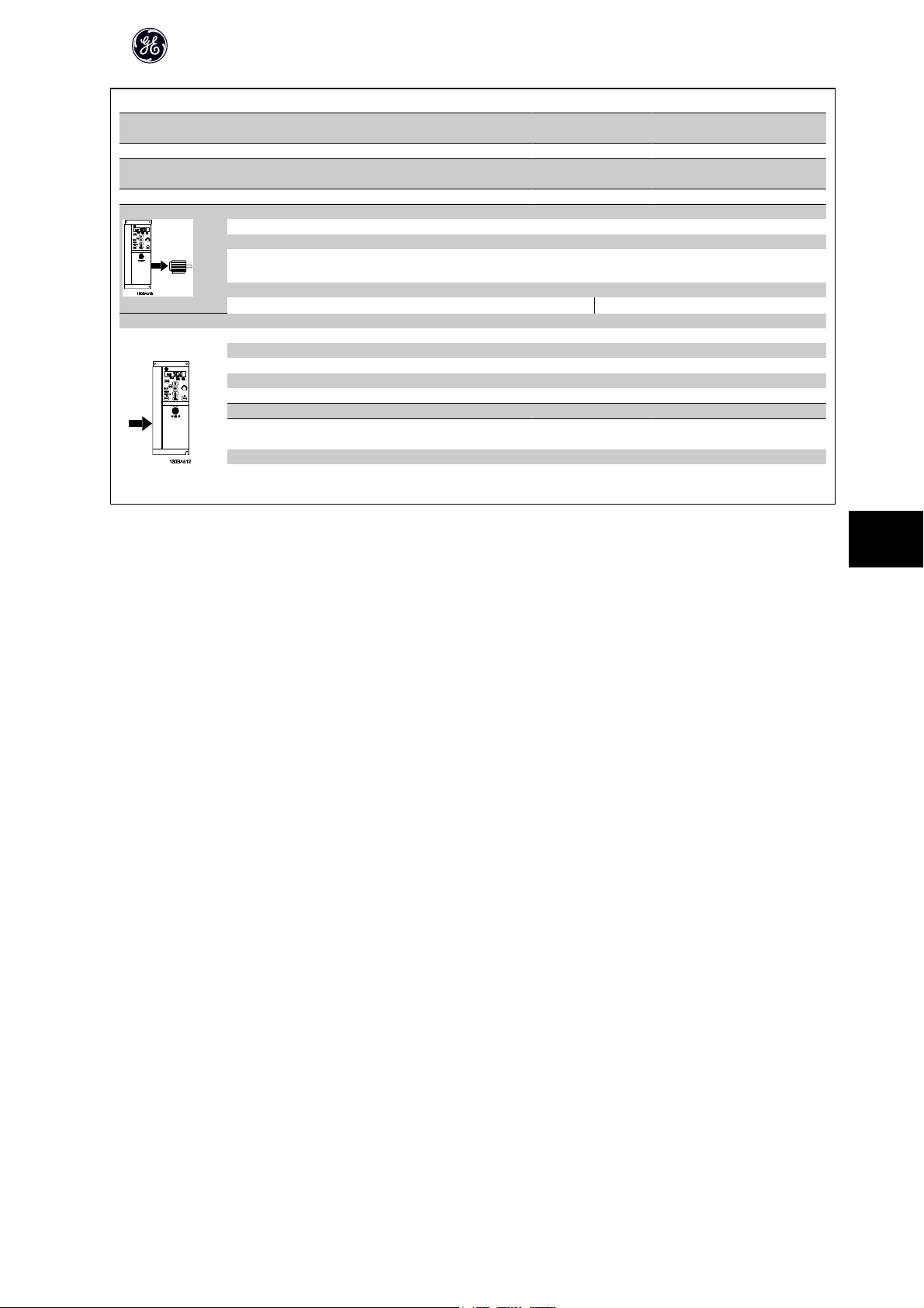
AF-60 LP™ Micro Drive Operating Instructions
Normal overload 150% for 1 minute
Frequency converter
Typical Shaft Output [kW]
Typical Shaft Output [HP] 7.5 10 15 20 25 30
IP 20
Output current
Max. input current
Continuous (3 x 380-440 V) [A] 12.0 15.5 23.0 31.0 37.0 43.0
Intermittent (3 x 380-440 V) [A] 18.0 23.5 34.5 46.5 55.5 64.5
Continuous (3 x 440-480 V) [A] 11.0 14.0 21.0 27.0 34.0 40.0
Intermittent (3 x 440-480 V) [A]
Max. cable size:
(mains, motor) [mm
Continuous (3 x 380-440 V ) [A] 19.2 24.8 33.0 42.0 34.7 41.2
Intermittent (3 x 380-440 V ) [A] 27.4 36.3 47.5 60.0 49.0 57.6
Continuous (3 x 440-480 V ) [A] 16.6 21.4 29.0 36.0 31.5 37.5
Intermittent (3 x 440-480 V ) [A] 23.6 30.1 41.0 52.0 44.0 53.0
Max. mains fuses [A] See Section Fuses
Environment
Estimated power loss [W], Best case/
1)
Typical
Weight enclosure IP20 [kg] 3.0 3.0
Efficiency [%], Best case/
1)
Typical
2
/ AWG]
5.5 7.5 11 15 18.5 22
Unit SizeM3Unit Size
16.5 21.3 31.5 40.5 51.0 60.0
131.0/
166.8
98.0/
97.5
M3
4/10 16/6
175.0/
217.5
98.0/
97.5
290.0/
342.0
97.8/
97.4
387.0/
454.0
97.7/
97.4
395.0/
428.0
98.1/
98.0
467.0/
520.0
98.1/
97.9
Table 8.4: Mains supply 3 x 380 - 480 VAC
1. At rated load conditions.
8
DET-579A
61
Page 63

AF-60 LP™ Micro Drive Operating Instructions
8.2 Other Specifications
Protection and Features:
• Electronic thermal motor protection against overload.
• Temperature monitoring of the heatsink ensures that the frequency converter trips in case of overtemperature
• The frequency converter is protected against short-circuits on motor terminals U, V, W.
• If a motor phase is missing, the frequency trips and issues an alarm.
• If a mains phase is missing, the frequency converter trips or issues a warning (depending on the load).
• Monitoring of the intermediate circuit voltage ensures that the frequency converter trips if the intermediate circuit voltage is too low or too high.
• The frequency converter is protected against earth faults on motor terminals U, V, W.
Mains supply (L1/L, L2, L3/N):
Supply voltage 200-240 V ±10%
Supply voltage 380-480 V ±10%
Supply frequency 50/60 Hz
Max. imbalance temporary between mains phases 3.0 % of rated supply voltage
True Power Factor (λ) ≥ 0.4 nominal at rated load
Displacement Power Factor (cosφ) near unity (> 0.98)
Switching on input supply L1/L, L2, L3/N (power-ups) maximum 2 times/min.
Environment according to EN60664-1 overvoltage category III/pollution degree 2
8
The unit is suitable for use on a circuit capable of delivering not more than 100.000 RMS symmetrical Amperes, 240/480 V maximum.
Motor output (U, V, W):
Output voltage 0 - 100% of supply voltage
Output frequency 0-200 Hz (Advanced Vector Control), 0-400 Hz (u/f)
Switching on output Unlimited
Ramp times 0.05 - 3600 sec.
Cable lengths and cross sections:
Max. motor cable length, screened/armoured (EMC correct installation) 15 m
Max. motor cable length, unscreened/unarmoured 50 m
Max. cross section to motor, mains*
Connection to load sharing/brake (M1, M2, M3) 6.3 mm insulated Faston Plugs
Max. cross section to load sharing/brake (M4, M5) 16 mm2/6AWG
Maximum cross section to control terminals, rigid wire 1.5 mm2/16 AWG (2 x 0.75 mm2)
Maximum cross section to control terminals, flexible cable 1 mm2/18 AWG
Maximum cross section to control terminals, cable with enclosed core 0.5 mm2/20 AWG
Minimum cross section to control terminals 0.25 mm
* See tables for mains supply for more information!
Digital inputs (Pulse/enocder inputs):
Programmable digital inputs (Pulse/encoder) 5 (1)
Terminal number 18, 19, 27, 29, 33,
Logic PNP or NPN
Voltage level 0 - 24 V DC
Voltage level, logic'0' PNP < 5 V DC
Voltage level, logic'1' PNP > 10 V DC
Voltage level, logic '0' NPN > 19 V DC
Voltage level, logic '1' NPN < 14 V DC
Maximum voltage on input 28 V DC
Input resistance, R
Max. pulse frequency at terminal 33 5000 Hz
Min. pulse frequency at terminal 33 20 Hz
i
2
approx. 4 k
62
DET-579A
Page 64

AF-60 LP™ Micro Drive Operating Instructions
Analog inputs:
Number of analog inputs 2
Terminal number 53, 60
Voltage mode (Terminal 53) Switch S200=OFF(U)
Current mode (Terminal 53 and 60) Switch S200=ON(I)
Voltage level 0 -10 V
Input resistance, R
Max. voltage 20 V
Current level 0/4 to 20 mA (scaleable)
Input resistance, R
Max. current 30 mA
Analog output:
Number of programmable analog outputs 1
Terminal number 42
Current range at analog output 0/4 - 20 mA
Max. resistor load to common at analog output 500 Ω
Accuracy on analog output Max. error: 0.8 % of full scale
Resolution on analog output 8 bit
The analog output is galvanically isolated from the supply voltage (PELV) and other high-voltage terminals.
Control card, RS-485 serial communication:
Terminal number 68 (P,TX+, RX+), 69 (N,TX-, RX-)
Terminal number 61 Common for terminals 68 and 69
The RS-485 serial communication circuit is functionally seated from other central circuits and galvanically isolated from the supply voltage (PELV).
Control card, 24 V DC output:
Terminal number 12
Max. load (M1 and M2) 160 mA
Max. load (M3) 30 mA
Max. load (M4 and M5) 200 mA
Relay output:
Programmable relay output 1
Relay 01 Terminal number 01-03 (break), 01-02(make)
Max. terminal load (AC-1)1) on 01-02 (NO) (Resistive load) 250 V AC, 2 A
Max. terminal load (AC-15)1) on 01-02 (NO) (Inductive load @ cosφ 0.4) 250 V AC, 0.2 A
Max. terminal load (DC-1)1) on 01-02 (NO) (Resistive load) 30 V DC, 2 A
Max. terminal load (DC-13)1) on 01-02 (NO) (Inductive load) 24 V DC, 0.1A
Max. terminal load (AC-1)1) on 01-03 (NC) (Resistive load) 250 V AC, 2 A
Max. terminal load (AC-15)1) on 01-03 (NC) (Inductive load @ cosφ 0.4) 250 V AC, 0.2A
Max. terminal load (DC-1)1) on 01-03 (NC) (Resistive load) 30 V DC, 2 A
Min. terminal load on 01-03 (NC), 01-02 (NO) 24 V DC 10 mA, 24 V AC 20 mA
Environment according to EN 60664-1 overvoltage category III/pollution degree 2
1) IEC 60947 part 4 and 5
i
i
approx. 10 kΩ
approx. 200 Ω
8
Control card, 10 V DC output:
Terminal number 50
Output voltage 10.5 V ±0.5 V
Max. load 25 mA
The 10 V DC supply is galvanically isolated from the supply voltage (PELV) and other high-voltage terminals.
Surroundings:
Enclosure IP 20
Enclosure kit available IP 21
Enclosure kit available TYPE 1
Vibration test 1.0 g
Max. relative humidity 5% - 95%(IEC 60721-3-3; Class 3K3 (non-condensing) during operation
Aggressive environment (IEC 60721-3-3), coated class 3C3
Test method according to IEC 60068-2-43 H2S (10 days)
DET-579A
63
Page 65

AF-60 LP™ Micro Drive Operating Instructions
Ambient temperature Max. 40 °C
Derating for high ambient temperature, see section on special conditions
Minimum ambient temperature during full-scale operation 0 °C
Minimum ambient temperature at reduced performance - 10 °C
Temperature during storage/transport -25 - +65/70 °C
Maximum altitude above sea level without derating 1000 m
Maximum altitude above sea level with derating 3000 m
Derating for high altitude, see section on special conditions
EMC standards, Emission EN 61800-3, EN 61000-6-3/4, EN 55011, IEC 61800-3
EN 61800-3, EN 61000-6-1/2, EN 61000-4-2, EN 61000-4-3,
EMC standards, Immunity
See section on special conditions
EN 61000-4-4, EN 61000-4-5, EN 61000-4-6
8
64
DET-579A
Page 66

AF-60 LP™ Micro Drive Operating Instructions
8.3 Special Conditions
8.3.1 The Purpose of Derating
Derating must be taken into account when using the frequency converter at low air pressure (heights), at low speeds or at high ambient temperature. The required
action is described in this section.
8.3.2 Derating for Ambient Temperature
The ambient temperature measured over 24 hours should be at least 5 °C lower than the max. ambient temperature.
If the frequency converter is operated at high ambient temperature, the continuous output current should be decreased.
The frequency converter has been designed for operation at max 50 °C ambient temperature with one motor size smaller than nominal. Continuous operation
at full load at 50 °C ambient temperature will reduce the lifetime of the frequency converter.
8.3.3 Derating for Low Air Pressure
The cooling capability of air is decreased at low air pressure.
For altitudes above 2000 m, please contact GE .
Below 1000 m altitude no de-rating is necessary but above 1000 m the ambient temperature or the maximum output current should be decreased.
Decrease the output by 1% per 100 m altitude above 1000 m or reduce the max. ambient temperature by 1 degree per 200 m
8.3.4 Derating for Running at Low Speeds
When a motor is connected to at frequency converter, it is necessary to check that the cooling of the motor is adequate.
A problem may occur at low speeds in constant torque applications. Running continuously at low speeds – below half the nominal motor speed – may require
additional air cooling. Alternatively, choose a larger motor (one size up).
8
DET-579A
65
Page 67
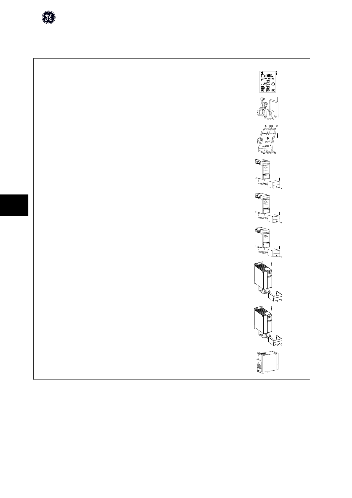
8.4
Options for AF-60 LP™ Micro Drive
Catalog No Description
KYPDACLP1 Keypad with
potentiometer
RMKYPDACLP1 Remote Mounting Kit for Keypad incl.
3 m cable, , IP21 rated.
AF-60 LP™ Micro Drive Operating Instructions
8
DEPLTACLP1
DEPLTACLP2
DEPLTACLP3
NEMA1ACLP1 NEMA Type 1 Kit for M1 Unit Size
NEMA1ACLP2 NEMA Type 1 Kit for M2 Unit Size
NEMA1ACLP3 NEMA Type 1 Kit for M3 Unit Size
NEMA1ACLP4 NEMA Type 1 Kit for M4 Unit Size
De-coupling plate kit for M1 and M2 Unit Sizes
De-coupling plate kit for M3 Unit Size
De-coupling plate kit for M4 and M5 Unit Size
NEMA1ACLP5 NEMA Type 1 Kit for M5 Unit Size
RMACLP1 DIN rail mounting kit for M1 Unit Size
GE Line Filters and brake resistors are available upon request.
66
DET-579A
Page 68

AF-60 LP™ Micro Drive Operating Instructions
Index
A
Active Set-up 19
Active Set-up 44, 49
Alarm, Warning And Extended Status Word 57
Ambient Temperature 64
Analog In/out 51
Analog Inputs 63
Analog Inputs: 63
Analog Output 63
B
Brake Resistor 49
Brake Resistor (ohm) 44
Brake Resistor Short-circuited 56
Brakes 49
Bus Termination 16
C
Cable Lengths And Cross Sections 62
Clearance 9
Comm. And Options 51
Configuration Mode 23
Control Card, 10 V Dc Output 63
Control Card, 24 V Dc Output 63
Control Card, Rs-485 Serial Communication: 63
Control Terminals 16
Control Word According To Fc Profile 37
Controllers 51
Conversion Index 48
D
Danfoss Fc Control Profile 37
Data Readouts 53
Dc-brake 45
Dc-brake 44
De-coupling Plate Kit 66
Derating For Ambient Temperature 65
Derating For Low Air Pressure 65
Derating For Running At Low Speeds 65
Digital In/out 50
Digital Inputs (pulse/enocder Inputs): 62
Digital Inputs: 62
Din Rail Mounting Kit 66
Display 19
Disposal Instruction 8
Drive Information 52
E
Earth Leakage Current 5, 7
Edit Set-up 19
Edit Set-up 44, 49
Electronic Waste 8
Emc-correct Installation 13
Explanation Of The Control Bits 37
Explanation Of The Status Bits 40
F
Frequency Converter With Modbus Rtu 27
Function Codes Supported By Modbus Rtu 31
DET-579A
67
Page 69

AF-60 LP™ Micro Drive Operating Instructions
H
Hand Mode 45
Hand Mode 49
How To Connect 11
I
Indicator Lights 20
Isolated Mains Source 7
It Mains 7
L
Lcp 11 19
Lcp 12 19
Leakage Current 7
Limits/warnings 50
Load Compensation 44, 49
Load Sharing/brake 18
Load/motor 49
M
Main Menu 20, 25
Mains Connection 13
Mains Supply 59, 60
Mains Supply (l1/l, L2, L3/n) 62
Mains Supply 1 X 200 - 240 Vac 59
Mains Supply 3 X 200 - 240 Vac 60
Mains Supply 3 X 380 - 480 Vac 60
Max. Reference 24
Maximum Reference 23
Mechanical Dimensions 10
Mechanical Installation 9
Min. Reference 23
Minimum Reference 23
Modbus Rtu 27
Modbus Rtu Message Framing Structure 28
Modbus Rtu Overview 27
Motor Connection 14
Motor Current 22
Motor Direction 20
Motor Frequency 22
Motor Nominal Speed 22
Motor Output (u, V, W): 62
Motor Overload Protection 7
Motor Phase 45, 50
Motor Power 22
Motor Protection 62
Motor Speed High Limit 24
Motor Speed Low Limit 24
Motor Temperature 44
Motor Voltage 22
N
Navigation Keys 21
O
Operation Keys 21
Operation/display 49
Options 66
Options For Vlt Micro Drive Fc 51 66
Other Specifications 62
Output Performance (u, V, W) 62
Overcurrent Protection 12
68
DET-579A
Page 70

AF-60 LP™ Micro Drive Operating Instructions
Over-voltage Control 44, 49
P
Parameter Number 20
Parameter Overview 43
Power Circuit - Overview 17
Preset Reference 24
Process Cl Feedback Resource 24
Process Feed Forward Factor 25
Process Pi Anti Windup 24
Process Pi Integral Time 25
Process Pi Normal/inverse 24
Process Pi Proportional Gain 24
Process Pi Start Speed 24
Protection 12
Protection And Features 62
Q
Quick Menu 20, 21
Quick Menu Parameters 22
R
Readout Mode 20
Reference/ramps 50
Relay Output 63
Remote Mounting Kit 66
Residual Current Device 7
S
S200 Switches 1-4 16
Serial Communication 21
Set-up Number 19
Set-up Software 19
Side-by-side Installation 9
Slip Compensation 44, 49
Smart Logic 52
Special Conditions 65
Special Functions 52
Specifications 59
Status Menu 20, 21
Status Word According To Fc Profile (stw) 39
Surroundings 63
Switches 16
T
Terminal 60 Filter Time Constant 24
Terminal 60 High Current 24
Terminal 60 High Feedback Value 24
Terminal 60 Low Current 24
Terminal 60 Low Feedback Value 24
Thermistor 44
Thermistor Resource 49
Troubleshooting 55
U
Ul Compliance 12
Unit 20
V
Value 20
Voltage Level 62
DET-579A
69
Page 71

AF-60 LP™ Micro Drive Operating Instructions
W
Warnings And Alarms 55, 56
70
DET-579A
Page 72

The instructions do not purport to cover all details or variations in equipment nor to provide for every possible
contingency to be met in connection with installation, operation or maintenance. Should further information be
desired or should particular problems arise which are not covered sufficiently for the purchaser’s purposes, the
matter should be referred to the GE company.
AF-60 LP is a trademark of the General Electric Company.
GE Consumer & Industrial
41 Woodford Avenue
Plainville, CT 06062
www.geelectrical.com/drives
132R0040
DET-579A
*MG02G202*
 Loading...