


GE ZBD6700, ZBD6600, ZBD6905, ZBD6900, ZBD7005 User Manual
...Installation
Instructions
If you have questions, call 800.626.2000 or visit our website at: www.monogram.com
Built-In Dishwashers
ZBD6400, ZBD6500, ZBD6600
ZBD6700, ZBD6900, ZBD7000,
ZBD7100
Chef’s Washers
ZBD6605, ZBD6905, ZBD7005,
ZBD7105
Design Guide with
Installation Instructions
Monogram.®
We bring good things to life.

Safety Information
BEFORE YOU BEGIN
Read these instructions completely and carefully.
• IMPORTANT - Save these instructions for local inspector’s use. Observe all governing
codes and ordinances.
• Note to Installer - Be sure to leave these instructions with the Consumer.
• Note to Consumer - Keep these instructions with your Owner’s Manual for future reference.
• Skill Level – Installation of this dishwasher requires basic mechanical and electrical skills. Proper installation is the responsibility of the installer. Product failure due to improper installation is not covered under the GE Appliance Warranty.
• Completion Time – 1 to 2 Hours. New installations require more time than replacement installations.
• IMPORTANT – The dishwasher MUST be installed to allow for future removal from the enclosure if service is required.
If you received a damaged dishwasher, you should immediately contact your dealer or builder.
READ CAREFULLY.
KEEP THESE INSTRUCTIONS.
FOR YOUR SAFETY
Read and observe all CAUTION and WARNINGS shown throughout these instructions.
For Monogram local service in your area, 1-800-444-1845.
For Monogram service in Canada 1-888-880-3030
For Monogram Parts and Accessories, call 1-800-626-2002.
CONTENTS
Design Information |
|
Installation Instructions |
|
Product Dimensions ....................................................... |
3 |
Step 1, Remove Packaging ........................................... |
10 |
Models Available ............................................................ |
3 |
Step 2, Install Leveling Legs ....................................... |
10 |
Advance Planning .......................................................... |
3 |
Step 3, Remove Access Covers .................................... |
10 |
Installation Preparation |
|
Step 4, Install 90° Elbow ............................................... |
10 |
Materials You Will Need ................................................. |
4 |
Step 5, Install Power Cord............................................ |
11 |
Tools You Will Need ....................................................... |
4 |
Step 6, Level Dishwasher .............................................. |
11 |
Parts Supplied ................................................................. |
5 |
Step 7, Slide Dishwasher into Opening....................... |
11 |
Prepare Dishwasher Enclosure ..................................... |
5 |
Step 8, Connect Water Line ........................................ |
11 |
Drain Requirements ....................................................... |
6 |
Step 9, Connect Drain Line ........................................ |
12 |
Prepare Electrical Wiring ............................................... |
7 |
Step 10, Connect Electrical ......................................... |
12 |
Prepare Hot Water Line ................................................. |
8 |
Step 11, Position and Level Dishwasher ...................... |
13 |
Custom Panel Dimensions |
|
Step 12, Pre-Test Check List ........................................ |
13 |
Custom Panels for ZBD6400 ......................................... |
9 |
Step 13, Dishwasher Wet Test ..................................... |
13 |
Custom Panels for ZBD7000, ZBD7005 ........................ |
9 |
Step 14, Secure Dishwasher |
|
|
|
to Cabinet or Countertop ....................................... |
14 |
|
|
Step 15, Install Toekick, Custom Toekick .................. |
14 |
|
|
Step 16, Install Side Trim Strips .................................. |
14 |
|
|
Panel Installation for Models |
|
|
|
ZBD7000 and ZBD7005 ............................................ |
15 |
2
Design Information
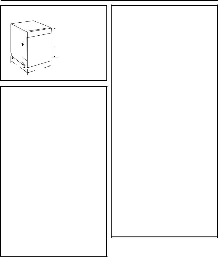
PRODUCT DIMENSIONS
|
|
34" |
|
|
Adjustable |
|
|
to 35" |
|
|
*Dishwasher model |
|
|
ZBD7000 and |
|
|
Chef’s Washer |
|
|
model ZBD7005 |
*24" |
|
require a 3/4" thick |
23-7/8" |
custom panel and |
|
|
will be 24-3/4" |
|
|
|
deep.
DISHWASHER MODELS
Traditional Built-In
ZBD6400 BB, Black - Accepts 1/4" or 3/4" custom panels
ZBD6400 WW White - Accepts 1/4" or 3/4" custom panels
Trim Kits for models ZBD6400
•ZPF625W (white) or ZPF625B (black) custom panel kits, supports a 1/4" thick custom door panel.
•ZPF675W (white) or ZPF675B (black) custom panel kits support a 3/4" thick custom door panel.
Traditional Built-In
ZBD6500 SS, Stainless steel door
Professional Series
ZBD6600 SS, Stainless Steel
Fully Wrapped
ZBD6700 BB, Black
ZBD6700 WW, White
ZBD6900 SS, Stainless steel with black controls
Fully Integrated
ZBD7000 II, Requires custom panel and handle ZBD7100 SS, Stainless steel with tubular handle
CHEF’S WASHER MODELS
Professional Series
ZBD6605 SS, Stainless steel
Fully Wrapped
ZBD6905 SS, Stainless steel
Fully Integrated
ZBD7005 II, Requires custom panel and handle ZBD7105 SS, Stainless steel with tubular handle
ADVANCE PLANNING
•These dishwashers are designed for versatility, adaptable to virtually any installation.
•All models have a full length door or a modified door to accept a full cabinet panel without the traditional access panel
•Side tub flange trim is adjustable and will conceal any slight gap between the dishwasher and adjacent cabinetry.
•These dishwashers may be installed beneath countertops of stone or other materials that will not accept screws. No trim kit required.
Standard installation in 24" deep cabinets
•In standard 24" deep cabinets, the dishwasher door will be flush with adjacent cabinetry.
•Models with 3/4" thick custom door panel will fit flush with adjacent cabinetry.
Supplied or Custom Toekicks
•A 2-piece toekick is supplied with all models. The toekick is height and depth adjustable.
•Depending on cabinetry style, a custom toekick can also be installed to match cabinetry. Care must be taken to assure door swing clearance above the toekick.
•A notched continuous toekick may be necessary to allow a long door panel, on models ZBD7000 and ZBD7005, to swing back and under the dishwasher.
ADA-Compliant
Installation below 34" high countertops
A reduced height installation (32-1/2" min.) beneath a 34" countertop, can be accomplished by removing the front leveling legs. The rear legs should be screwed in flush with the bottom support, as shipped. The front of the dishwasher must be shimmed to level the dishwasher. Water and electrical must be routed through the back wall.
•All models are ADA-Compliant. Models ZBD7000 and ZBD7005 offer even more installation and design flexibility because the required custom door panel may be sized from 26-1/4 to 30-1/4" height. See page 9 for details.
3

Installation Preparation
MATERIALS YOU WILL NEED:
Materials Required for All Installations
♦ 90° Elbow (3/8”NPT external thread on one end, opposite end sized to fit water supply)
Note: Use new ferrule. Do not use old parts.
♦Strain relief for electrical connection
♦Thread seal tape
♦UL Listed wire connectors (3)
♦Screw type hose clamps
Screw Type Clamps
90° Elbow
Wire Nuts |
Strain Relief |
Thread Seal
Tape
Materials For New Installations Only:
♦ Air gap for drain hose, if required
♦ Waste tee for house plumbing, if applicable |
|
|
|
♦ Electrical cable or power cord, if applicable |
Shut-Off |
Electrical Cable |
|
Waste Tee |
Valve |
||
or Power Cord |
|||
♦ Hand shut-off valve (recommended) |
|
||
♦ Water line 3/8” min. copper or 1/2” min. plastic (plastic |
|
|
|
must be tested for temperature and pressure) |
|
|
|
♦ Coupler for extending drain line, if applicable |
|
|
|
Air |
Coupler |
|
|
|
|
||
Gap |
|
Hot Water Line |
TOOLS YOU WILL NEED: |
Flat Blade Screwdriver |
Tools Required for All Installations
♦Phillips head and flat blade screwdrivers
♦3/8”, 5/16” and 1/4” nutdrivers
♦ Level |
|
Safety Glasses |
|
|
|
||
♦ Carpenters square |
|
|
|
♦ Measuring tape |
|
|
|
♦ Safety glasses |
Wire Strippers |
|
|
♦ Flashlight |
Adjustable |
||
|
|||
♦ Bucket to catch water when flushing the line |
Wrench |
||
Bucket |
|||
♦Tubing cutter
♦Gloves to protect against sharp edges
♦Wire strippers
For New Installations Only:
Measuring Tape
♦ Drill and appropriate bits ♦ Hole saw set
Level
|
Nut Driver |
Phillips |
Head |
Screwdriver |
|
|
Tubing |
|
Cutter |
Flashlight |
|
|
Drill |
|
and Bits |
|
Square |
|
Hole |
|
Saw Set |
Gloves
4
|
Installation Preparation |
|
|
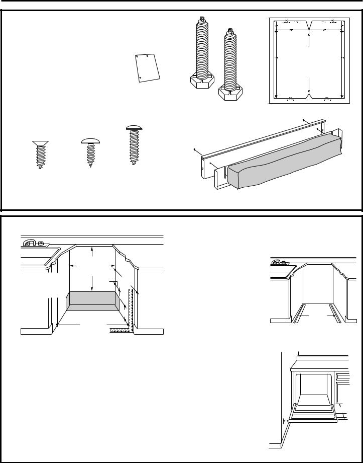
PARTS SUPPLIED: |
|
|
|
Remove the hardware accessory bag and other parts |
|
|
|
from inside or taped to the outside of the dishwasher. |
|
|
|
Check contents against illustrations to insure that all |
|
Template |
|
parts are included. |
|
|
for |
|
|
|
ZBD7000 |
♦ 2-piece toekick |
|
|
ZBD7005 |
|
|
Only |
|
♦ 6 screws (see illustration) |
|
|
|
♦ 2 leveling legs |
Junction |
|
|
♦ Template for the installation of a |
Box Cover |
|
|
with screws |
2 Leveling Legs |
|
|
|
Template with Mounting Hardware |
||
custom panel packed with models |
|
||
ZBD7000 and ZBD7005 only |
|
|
|
♦ Junction box cover |
|
|
|
Screws A |
Screws B |
Screws C |
Insulation |
|
|
||||
(2) Countertop |
(2) Cabinet |
(2) Color |
|
|
Mounting |
Mounting |
Matched |
2-Piece Toekick with |
|
Screws |
Screws |
Toekick |
||
Sound Insulation |
||||
|
|
Screws |
||
|
|
|
PREPARE DISHWASHER ENCLOSURE
|
This Wall Area |
|
|
|
must be Free of |
|
|
34" to 35" |
Pipes or Wires |
24" |
|
1-3/4" |
|||
Underside |
Min. |
||
of Countertop |
|
|
|
to Floor |
|
|
|
|
|
6" |
|
|
23-7/8" Min. |
|
|
|
24-1/4" Max |
|
*Models ZBD7000 and ZBD7005 with custom panels are 24-3/4" deep
•The rough cabinet opening must be at least 24” deep, 23-7/8”min. to 24-1/4” wide. The height should be 34” min. and 35” max.
Note: ADA installation, beneath 34" high countertops may be accomplished by removing front leveling legs. Drain hose, water and electrical must be routed through the cutout on the back of the dishwasher.
•The dishwasher must be installed so that drain hose is no more than 10 feet in length for proper drainage.
•The dishwasher must be fully enclosed on the top, sides and back, but should not support any part of the enclosure.
•The floor inside the opening must be even and level with the finished floor of the kitchen. If the kitchen floor is tile, it may be
higher than the floor of the installation cutout. Pieces of wood may be placed into the cutout floor to make it level or higher than the room
floor. This will allow easy removal for any future service.
Corner Installation
•When installing into a corner, allow 2" min. clearance between dishwasher and adjacent cabinet or wall.
•Allow 24-1/8" min. clearance from the front of the dishwasher for door opening.
24-1/8"
 Clearance for Door Opening 2" Minimum
5
 Loading...