

Page 1

GE Healthcare
LOGIQ E9
Service Manual
11/19/12
GEHC_FRNT_CVR.FM
Part Number: 5180263-100
Revision: Rev 5
Page 2

Page 3

GE HEALTHCARE
WARNING
(EN)
AVERTISSEMENT
(FR)
WARNUNG
(DE)
DIRECTION 5180263-100, REV 5 LOGIQ E9 Service Manual
Important Precautions
THIS SERVICE MANUAL IS AVAILABLE IN ENGLISH ONLY.
• IF A CUSTOMER’S SERVICE PROVIDER REQUIRES A LANGUAGE OTHER
THAN ENGLISH, IT IS THE CUSTOMER’S RESPONSIBILITY TO PROVIDE
TRANSLATION SERVICES.
• DO NOT ATTEMPT TO SERVICE THE EQUIPMENT UNLESS THIS SERVICE
MANUAL HAS BEEN CONSULTED AND IS UNDERSTOOD.
• FAILURE TO HEED THIS WARNING MAY RESULT IN INJURY TO THE SERVICE
PROVIDER, OPERATOR OR PATIENT FROM ELECTRIC SHOCK, MECHANICAL
OR OTHER HAZARDS.
CE MANUEL DE MAINTENANCE N’EST DISPONIBLE QU’EN ANGLAIS.
• SI LE TECHNICIEN DU CLIENT A BESOIN DE CE MANUEL DANS UNE AUTRE
LANGUE QUE L’ANGLAIS, C’EST AU CLIENT QU’IL INCOMBE DE LE FAIRE
TRADUIRE.
• NE PAS TENTER D’INTERVENTION SUR LES ÉQUIPEMENTS TANT QUE LE
MANUEL SERVICE N’A PAS ÉTÉ CONSULTÉ ET COMPRIS.
• LE NON-RESPECT DE CET AVERTISSEMENT PEUT ENTRAÎNER CHEZ LE
TECHNICIEN, L’OPÉRATEUR OU LE PATIENT DES BLESSURES DUES À DES
DANGERS ÉLECTRIQUES, MÉCANIQUES OU AUTRES.
DIESES KUNDENDIENST-HANDBUCH EXISTIERT NUR IN ENGLISCHER
SPRACHE.
• FALLS EIN FREMDER KUNDENDIENST EINE ANDERE SPRACHE BENÖTIGT,
IST ES AUFGABE DES KUNDEN FÜR EINE ENTSPRECHENDE ÜBERSETZUNG
ZU SORGEN.
• VERSUCHEN SIE NICHT, DAS GERÄT ZU REPARIEREN, BEVOR DIESES
KUNDENDIENST-HANDBUCH NICHT ZU RATE GEZOGEN UND VERSTANDEN
WURDE.
• WIRD DIESE WARNUNG NICHT BEACHTET, SO KANN ES ZU VERLETZUNGEN
DES KUNDENDIENSTTECHNIKERS, DES BEDIENERS ODER DES PATIENTEN
DURCH ELEKTRISCHE SCHLÄGE, MECHANISCHE ODER SONSTIGE
GEFAHREN KOMMEN.
iii
Page 4

GE HEALTHCARE
AVISO
(ES)
ATENÇÃO
(PT-Br)
(PT-pt)
AVISO
AVVERTENZA
(IT)
DIRECTION 5180263-100, REV 5 LOGIQ E9 Service Manual
ESTE MANUAL DE SERVICIO SÓLO EXISTE EN INGLÉS.
• SI ALGÚN PROVEEDOR DE SERVICIOS AJENO A GEHC SOLICITA UN IDIOMA
QUE NO SEA EL INGLÉS, ES RESPONSABILIDAD DEL CLIENTE OFRECER UN
SERVICIO DE TRADUCCIÓN.
• NO SE DEBERÁ DAR SERVICIO TÉCNICO AL EQUIPO, SIN HABER
CONSULTADO Y COMPRENDIDO ESTE MANUAL DE SERVICIO.
• LA NO OBSERVANCIA DEL PRESENTE AVISO PUEDE DAR LUGAR A QUE EL
PROVEEDOR DE SERVICIOS, EL OPERADOR O EL PACIENTE SUFRAN
LESIONES PROVOCADAS POR CAUSAS ELÉCTRICAS, MECÁNICAS O DE
OTRA NATURALEZA.
ESTE MANUAL DE ASSISTÊNCIA TÉCNICA SÓ SE ENCONTRA DISPONÍVEL EM
INGLÊS.
• SE QUALQUER OUTRO SERVIÇO DE ASSISTÊNCIA TÉCNICA, QUE NÃO A
GEHC, SOLICITAR ESTES MANUAIS NOUTRO IDIOMA, É DA
RESPONSABILIDADE DO CLIENTE FORNECER OS SERVIÇOS DE TRADUÇÃO.
• NÃO TENTE REPARAR O EQUIPAMENTO SEM TER CONSULTADO E
COMPREENDIDO ESTE MANUAL DE ASSISTÊNCIA TÉCNICA.
• O NÃO CUMPRIMENTO DESTE AVISO PODE POR EM PERIGO A SEGURANÇA
DO TÉCNICO, OPERADOR OU PACIENTE DEVIDO A‘ CHOQUES ELÉTRICOS,
MECÂNICOS OU OUTROS.
ESTE MANUAL DE ASSISTÊNCIA ESTÁ DISPONÍVEL APENAS EM INGLÊS.
• SE QUALQUER OUTRO SERVIÇO DE ASSISTÊNCIA TÉCNICA, QUE NÃO A
GEHC, SOLICITAR ESTES MANUAIS NOUTRO IDIOMA, É DA
RESPONSABILIDADE DO CLIENTE FORNECER OS SERVIÇOS DE TRADUÇÃO.
• NÃO TENTE EFECTUAR REPARAÇÕES NO EQUIPAMENTO SEM TER
CONSULTADO E COMPREENDIDO PREVIAMENTE ESTE MANUAL.
• A INOBSERVÂNCIA DESTE AVISO PODE RESULTAR EM FERIMENTOS NO
TÉCNICO DE ASSISTÊNCIA, OPERADOR OU PACIENTE EM CONSEQUÊNCIA
DE CHOQUE ELÉCTRICO, PERIGOS DE ORIGEM MECÂNICA, BEM COMO DE
OUTROS TIPOS.
IL PRESENTE MANUALE DI MANUTENZIONE È DISPONIBILE SOLTANTO IN
INGLESE.
• SE UN ADDETTO ALLA MANUTENZIONE ESTERNO ALLA GEHC RICHIEDE IL
MANUALE IN UNA LINGUA DIVERSA, IL CLIENTE È TENUTO A PROVVEDERE
DIRETTAMENTE ALLA TRADUZIONE.
• SI PROCEDA ALLA MANUTENZIONE DELL’APPARECCHIATURA SOLO DOPO
AVER CONSULTATO IL PRESENTE MANUALE ED AVERNE COMPRESO IL
CONTENUTO.
• NON TENERE CONTO DELLA PRESENTE AVVERTENZA POTREBBE FAR
COMPIERE OPERAZIONI DA CUI DERIVINO LESIONI ALL’ADDETTO ALLA
MANUTENZIONE, ALL’UTILIZZATORE ED AL PAZIENTE PER FOLGORAZIONE
ELETTRICA, PER URTI MECCANICI OD ALTRI RISCHI.
iv -
Page 5

GE HEALTHCARE
HOIATUS
(ET)
VAROITUS
(FI)
ΠΡΟΕΙΔΟΠΟΙΗΣΗ
(EL)
FIGYELMEZTETÉS
(HU)
DIRECTION 5180263-100, REV 5 LOGIQ E9 Service Manual
KÄESOLEV TEENINDUSJUHEND ON SAADAVAL AINULT INGLISE KEELES.
• KUI KLIENDITEENINDUSE OSUTAJA NÕUAB JUHENDIT INGLISE KEELEST
ERINEVAS KEELES, VASTUTAB KLIENT TÕLKETEENUSE OSUTAMISE EEST.
• ÄRGE ÜRITAGE SEADMEID TEENINDADA ENNE EELNEVALT KÄESOLEVA
TEENINDUSJUHENDIGA TUTVUMIST JA SELLEST ARU SAAMIST.
• KÄESOLEVA HOIATUSE EIRAMINE VÕIB PÕHJUSTADA TEENUSEOSUTAJA,
OPERAATORI VÕI PATSIENDI VIGASTAMIST ELEKTRILÖÖGI, MEHAANILISE
VÕI MUU OHU TAGAJÄRJEL.
TÄMÄ HUOLTO-OHJE ON SAATAVILLA VAIN ENGLANNIKSI.
• JOS ASIAKKAAN PALVELUNTARJOAJA VAATII MUUTA KUIN
ENGLANNINKIELISTÄ MATERIAALIA, TARVITTAVAN KÄÄNNÖKSEN
HANKKIMINEN ON ASIAKKAAN VASTUULLA.
• ÄLÄ YRITÄ KORJATA LAITTEISTOA ENNEN KUIN OLET VARMASTI LUKENUT
JA YMMÄRTÄNYT TÄMÄN HUOLTO-OHJEEN.
• MIKÄLI TÄTÄ VAROITUSTA EI NOUDATETA, SEURAUKSENA VOI OLLA
PALVELUNTARJOAJAN, LAITTEISTON KÄYTTÄJÄN TAI POTILAAN
VAHINGOITTUMINEN SÄHKÖISKUN, MEKAANISEN VIAN TAI MUUN
VAARATILANTEEN VUOKSI.
ΤΟ ΠΑΡΟΝ ΕΓΧΕΙΡΙΔΙΟ ΣΕΡΒΙΣ ΔΙΑΤΙΘΕΤΑΙ ΣΤΑ ΑΓΓΛΙΚΑ ΜΟΝΟ.
• ΕΑΝ ΤΟ ΑΤΟΜΟ ΠΑΡΟΧΗΣ ΣΕΡΒΙΣ ΕΝΟΣ ΠΕΛΑΤΗ ΑΠΑΙΤΕΙ ΤΟ ΠΑΡΟΝ
ΕΓΧΕΙΡΙΔΙΟ ΣΕ ΓΛΩΣΣΑ ΕΚΤΟΣ ΤΩΝ ΑΓΓΛΙΚΩΝ, ΑΠΟΤΕΛΕΙ ΕΥΘΥΝΗ ΤΟΥ
ΠΕΛΑΤΗ ΝΑ ΠΑΡΕΧΕΙ ΥΠΗΡΕΣΙΕΣ ΜΕΤΑΦΡΑΣΗΣ.
• ΜΗΝ ΕΠΙΧΕΙΡΗΣΕΤΕ ΤΗΝ ΕΚΤΕΛΕΣΗ ΕΡΓΑΣΙΩΝ ΣΕΡΒΙΣ ΣΤΟΝ ΕΞΟΠΛΙΣΜΟ
ΕΚΤΟΣ ΕΑΝ ΕΧΕΤΕ ΣΥΜΒΟΥΛΕΥΤΕΙ ΚΑΙ ΕΧΕΤΕ ΚΑΤΑΝΟΗΣΕΙ ΤΟ ΠΑΡΟΝ
ΕΓΧΕΙΡΙΔΙΟ ΣΕΡΒΙΣ
.
• ΕΑΝ ΔΕ ΛΑΒΕΤΕ ΥΠΟΨΗ ΤΗΝ ΠΡΟΕΙΔΟΠΟΙΗΣΗ ΑΥΤΗ, ΕΝΔΕΧΕΤΑΙ ΝΑ
ΠΡΟΚΛΗΘΕΙ ΤΡΑΥΜΑΤΙΣΜΟΣ ΣΤΟ ΑΤΟΜΟ ΠΑΡΟΧΗΣ ΣΕΡΒΙΣ, ΣΤΟ ΧΕΙΡΙΣΤΗ Ή
ΣΤΟΝ ΑΣΘΕΝΗ ΑΠΟ ΗΛΕΚΤΡΟΠΛΗΞΙΑ, ΜΗΧΑΝΙΚΟΥΣ Ή ΑΛΛΟΥΣ ΚΙΝΔΥΝΟΥΣ.
EZEN KARBANTARTÁSI KÉZIKÖNYV KIZÁRÓLAG ANGOL NYELVEN ÉRHETŐ EL.
• HA A VEVŐ SZOLGÁLTATÓJA ANGOLTÓL ELTÉRŐ NYELVRE TART IGÉNYT,
AKKOR A VEVŐ FELELŐSSÉGE A FORDÍTÁS ELKÉSZÍTTETÉSE.
• NE PRÓBÁLJA ELKEZDENI HASZNÁLNI A BERENDEZÉST, AMÍG A
KARBANTARTÁSI KÉZIKÖNYVBEN LEÍRTAKAT NEM ÉRTELMEZTÉK.
• EZEN FIGYELMEZTETÉS FIGYELMEN KÍVÜL HAGYÁSA A SZOLGÁLTATÓ,
MŰKÖDTETŐ VAGY A BETEG ÁRAMÜTÉS, MECHANIKAI VAGY EGYÉB
VESZÉLYHELYZET MIATTI SÉRÜLÉSÉT EREDMÉNYEZHETI.
v
Page 6

GE HEALTHCARE
VIÐVÖRUN
(IS)
VÝSTRAHA
(CS)
ADVARSEL
(DA)
WAARSCHUWING
(NL)
DIRECTION 5180263-100, REV 5 LOGIQ E9 Service Manual
ÞESSI ÞJÓNUSTUHANDBÓK ER EINGÖNGU FÁANLEG Á ENSKU.
• EF ÞJÓNUSTUAÐILI VIÐSKIPTAMANNS ÞARFNAST ANNARS TUNGUMÁLS EN
ENSKU, ER ÞAÐ Á ÁBYRGÐ VIÐSKIPTAMANNS AÐ ÚTVEGA ÞÝÐINGU.
• REYNIÐ EKKI AÐ ÞJÓNUSTA TÆKIÐ NEMA EFTIR AÐ HAFA SKOÐAÐ OG
SKILIÐ ÞESSA ÞJÓNUSTUHANDBÓK.
• EF EKKI ER FARIÐ AÐ ÞESSARI VIÐVÖRUN GETUR ÞAÐ VALDIÐ MEIÐSLUM
ÞJÓNUSTUVEITANDA, STJÓRNANDA EÐA SJÚKLINGS VEGNA RAFLOSTS,
VÉLRÆNNAR EÐA ANNARRAR HÆTTU.
TENTO SERVISNÍ NÁVOD EXISTUJE POUZE V ANGLICKÉM JAZYCE.
•VPŘÍPADĚ, ŽE POSKYTOVATEL SLUŽEB ZÁKAZNÍKŮM POTŘEBUJE NÁVOD
V JINÉM JAZYCE, JE ZAJIŠTĚNÍ PŘEKLADU DO ODPOVÍDAJÍCÍHO JAZYKA
ÚKOLEM ZÁKAZNÍKA.
• NEPROVÁDĚJTE ÚDRŽBU TOHOTO ZAŘÍZENÍ, ANIŽ BYSTE SI PŘEČETLI
TENTO SERVISNÍ NÁVOD A POCHOPILI JEHO OBSAH.
•VPŘÍPADĚ NEDODRŽOVÁNÍ TÉTO VÝSTRAHY MŮŽE DOJÍT ÚRAZU
ELEKTRICKÁM PROUDEM PRACOVNÍKA POSKYTOVATELE SLUŽEB,
OBSLUŽNÉHO PERSONÁLU NEBO PACIENTŮ VLIVEM ELEKTRICKÉHOP
PROUDU, RESPEKTIVE VLIVEM K RIZIKU MECHANICKÉHO POŠKOZENÍ NEBO
JINÉMU RIZIKU.
DENNE SERVICEMANUAL FINDES KUN PÅ ENGELSK.
• HVIS EN KUNDES TEKNIKER HAR BRUG FOR ET ANDET SPROG END
ENGELSK, ER DET KUNDENS ANSVAR AT SØRGE FOR OVERSÆTTELSE.
• FORSØG IKKE AT SERVICERE UDSTYRET MEDMINDRE
DENNE SERVICEMANUAL ER BLEVET LÆST OG FORSTÅET.
• MANGLENDE OVERHOLDELSE AF DENNE ADVARSEL KAN MEDFØRE SKADE
PÅ GRUND AF ELEKTRISK, MEKANISK ELLER ANDEN FARE FOR
TEKNIKEREN, OPERATØREN ELLER PATIENTEN.
DEZE ONDERHOUDSHANDLEIDING IS ENKEL IN HET ENGELS VERKRIJGBAAR.
• ALS HET ONDERHOUDSPERSONEEL EEN ANDERE TAAL VEREIST, DAN IS DE
KLANT VERANTWOORDELIJK VOOR DE VERTALING ERVAN.
• PROBEER DE APPARATUUR NIET TE ONDERHOUDEN VOORDAT DEZE
ONDERHOUDSHANDLEIDING WERD GERAADPLEEGD EN BEGREPEN IS.
• INDIEN DEZE WAARSCHUWING NIET WORDT OPGEVOLGD, ZOU HET
ONDERHOUDSPERSONEEL, DE OPERATOR OF EEN PATIËNT GEWOND
KUNNEN RAKEN ALS GEVOLG VAN EEN ELEKTRISCHE SCHOK,
MECHANISCHE OF ANDERE GEVAREN.
vi -
Page 7

GE HEALTHCARE
BRĪDINĀJUMS
(LV)
ĮSPĖJIMAS
(LT)
ADVARSEL
(NO)
OSTRZEŻENIE
(PL)
DIRECTION 5180263-100, REV 5 LOGIQ E9 Service Manual
ŠĪ APKALPES ROKASGRĀMATA IR PIEEJAMA TIKAI ANGĻU VALODĀ.
• JA KLIENTA APKALPES SNIEDZĒJAM NEPIECIEŠAMA INFORMĀCIJA CITĀ
VALODĀ, NEVIS ANGĻU, KLIENTA PIENĀKUMS IR NODROŠINĀT TULKOŠANU.
• NEVEICIET APRĪKOJUMA APKALPI BEZ APKALPES ROKASGRĀMATAS
IZLASĪŠANAS UN SAPRAŠANAS.
•ŠĪ BRĪDINĀJUMA NEIEVĒROŠANA VAR RADĪT ELEKTRISKĀS STRĀVAS
TRIECIENA, MEHĀNISKU VAI CITU RISKU IZRAISĪTU TRAUMU APKALPES
SNIEDZĒJAM, OPERATORAM VAI PACIENTAM.
ŠIS EKSPLOATAVIMO VADOVAS YRA IŠLEISTAS TIK ANGLŲ KALBA.
• JEI KLIENTO PASLAUGŲ TEIKĖJUI REIKIA VADOVO KITA KALBA – NE ANGLŲ,
VERTIMU PASIRŪPINTI TURI KLIENTAS.
•NEMĖGINKITE ATLIKTI ĮRANGOS TECHNINĖS PRIEŽIŪROS DARBŲ, NEBENT
VADOVAUTUMĖTĖS ŠIUO EKSPLOATAVIMO VADOVU IR JĮ SUPRASTUMĖTE
• NEPAISANT ŠIO PERSPĖJIMO, PASLAUGŲ TEIKĖJAS, OPERATORIUS AR
PACIENTAS GALI BŪTI SUŽEISTAS DĖL ELEKTROS SMŪGIO, MECHANINIŲ AR
KITŲ PAVOJŲ.
DENNE SERVICEHÅNDBOKEN FIN
NES BARE PÅ ENGELSK.
• HVIS KUNDENS SERVICELEVERANDØR TRENGER ET ANNET SPRÅK, ER DET
KUNDENS ANSVAR Å SØRGE FOR OVERSETTELSE.
• IKKE FORSØK Å REPARERE UTSTYRET UTEN AT DENNE
SERVICEHÅNDBOKEN ER LEST OG FORSTÅTT.
• MANGLENDE HENSYN TIL DENNE ADVARSELEN KAN FØRE TIL AT
SERVICELEVERANDØREN, OPERATØREN ELLER PASIENTEN SKADES PÅ
GRUNN AV ELEKTRISK STØT, MEKANISKE ELLER ANDRE FARER.
NINIEJSZY PODRĘCZNIK SERWISOWY DOSTĘPNY JEST JEDYNIE W JĘZYKU
ANGIELSKIM.
•JEŚLI FIRMA ŚWIADCZĄCA KLIENTOWI USłUGI SERWISOWE WYMAGA
UDOSTĘPNIENIA PODRĘCZNIKA W JĘZYKU INNYM NIŻ ANGIELSKI,
OBOWIĄZEK ZAPEWNIENIA STOSOWNEGO TłUMACZENIA SPOCZYWA NA
KLIENCIE.
• NIE PRÓBOWAĆ SERWISOWAĆ NINIEJSZEGO SPRZĘTU BEZ UPRZEDNIEGO
ZAPOZNANIA SIĘ Z PODRĘCZNIKIEM SERWISOWYM.
• NIEZASTOSOWANIE SIĘ DO TEGO OSTRZEŻENIA MOżE GROZIĆ
OBRAŻENIAMI CIAłA SERWISANTA, OPERATORA LUB PACJENTA W WYNIKU
PORAŻENIA PRĄDEM, URAZU MECHANICZNEGO LUB INNEGO RODZAJU
ZAGROŻEŃ.
vii
Page 8

GE HEALTHCARE
ATENŢIE
(RO)
ОСТОРОЖНО!
(RU)
(BG)
ПРЕДУПРЕЖДЕНИЕ
UPOZORENJE
(SR)
DIRECTION 5180263-100, REV 5 LOGIQ E9 Service Manual
ACEST MANUAL DE SERVICE ESTE DISPONIBIL NUMAI ÎN LIMBA ENGLEZĂ.
• DACĂ UN FURNIZOR DE SERVICII PENTRU CLIENŢI NECESITĂ O ALTĂ LIMBĂ
DECÂT CEA ENGLEZĂ, ESTE DE DATORIA CLIENTULUI SĂ FURNIZEZE O
TRADUCERE.
• NU ÎNCERCAŢI SĂ REPARAŢI ECHIPAMENTUL DECÂT ULTERIOR
CONSULTĂRII ŞI ÎNŢELEGERII ACESTUI MANUAL DE SERVICE.
• IGNORAREA ACESTUI AVERTISMENT AR PUTEA DUCE LA RĂNIREA
DEPANATORULUI, OPERATORULUI SAU PACIENTULUI ÎN URMA
PERICOLELOR DE ELECTROCUTARE, MECANICE SAU DE ALTĂ NATURĂ.
ДАННОЕ РУКОВОДСТВО ПО ОБСЛУЖИВАНИЮ ПРЕДОСТАВЛЯЕТСЯ ТОЛЬКО
НА АНГЛИЙСКОМ ЯЗЫКЕ.
• ЕСЛИ СЕРВИСНОМУ ПЕРСОНАЛУ КЛИЕНТА НЕОБХОДИМО РУКОВОДСТВО
НЕ НА АНГЛИЙСКОМ ЯЗЫКЕ, КЛИЕНТУ СЛЕДУЕТ САМОСТОЯТЕЛЬНО
ОБЕСПЕЧИТЬ ПЕРЕВОД.
• ПЕРЕД ОБСЛУЖИВАНИЕМ ОБОРУДОВАНИЯ ОБЯЗАТЕЛЬНО ОБРАТИТЕСЬ
К ДАНН
• НЕСОБ
ОМУ РУКОВОДСТВУ И ПОЙМИТЕ ИЗЛОЖЕННЫЕ В НЕМ СВЕДЕНИЯ.
ЛЮДЕНИЕ УКАЗАННЫХ ТРЕБОВАНИЙ МОЖЕТ ПРИВЕСТИ К ТОМУ,
ЧТО СПЕЦИАЛИСТ ПО ТЕХОБСЛУЖИВАНИЮ, ОПЕРАТОР ИЛИ ПАЦИЕНТ
ПОЛУЧАТ УДАР ЗЛЕКТРИЧЕСКИМ ТОКОМ, МЕХАНИЧЕСКУЮ ТРАВМУ ИЛИ
ДРУГОЕ ПОВРЕЖДЕНИЕ.
ТОВА СЕРВИЗНО РЪКОВОДСТВО Е НАЛИЧНО САМО НА АНГЛИЙСКИ ЕЗИК.
• АКО ДОСТАВЧИКЪТ НА СЕРВИЗНИ УСЛУГИ НА КЛИЕНТ СЕ НУЖДАЕ ОТ
ЕЗ
ИК, РАЗЛИЧЕН
ОТ АНГЛИЙСКИ, ЗАДЪЛЖЕНИЕ НА КЛИЕНТА Е ДА
ПРЕДОСТАВИ ПРЕВОДАЧЕСКА УСЛУГА.
• НЕ СЕ ОПИТВАЙТЕ ДА ИЗВЪРШВАТЕ СЕРВИЗНО ОБСЛУЖВАНЕ НА ТОВА
ОБОРУДВАНЕ, ОСВЕН ВСЛУЧАЙ, ЧЕ СЕРВИЗНОТО РЪКОВОДСТВО Е
ПРОЧЕТЕНО И СЕ РАЗБИРА.
• НЕСПАЗВАНЕТО НА ТОВА ПРЕДУПРЕЖДЕНИЕ МОЖЕ ДА ДОВЕДЕ ДО
НАРАНЯВАНЕ НА ДОСТАВЧИКА НА СЕРВИЗНИ УСЛУГИ, НА ОПЕРАТОРА
ИЛИ ПАЦИЕНТА ВСЛЕДСТВИЕНА ТОКОВ УДАР, МЕХ
АНИЧНИ ИЛИ ДРУГИ
РИСКОВЕ.
OVAJ PRIRUČNIK ZA SERVISIRANJE DOSTUPAN JE SAMO NA ENGLESKOM
JEZIKU.
• AKO KLIJENTOV SERVISER ZAHTEVA JEZIK KOJI NIJE ENGLESKI,
ODGOVORNOST JE NA KLIJENTU DA PRUŽI USLUGE PREVOĐENJA.
• NEMOJTE POKUŠAVATI DA SERVISIRATE OPREMU AKO NISTE PROČITALI I
RAZUMELI PRIRUČNIK ZA SERVISIRANJE.
• AKO NE POŠTUJETE OVO UPOZORENJE, MOŽE DOĆI DO POVREĐIVANJA
SERVISERA, OPERATERA ILI PACIJENTA UZROKOVANOG ELEKTRIČNIM
UDAROM, MEHANIČKIM I DRUGIM OPASNOSTIMA.
viii -
Page 9

GE HEALTHCARE
OPOZORILO
(SL)
UPOZORENJE
(HR)
UPOZORNENIE
(SK)
VARNING
(SV)
DIRECTION 5180263-100, REV 5 LOGIQ E9 Service Manual
TA SERVISNI PRIROČNIK JE NA VOLJO SAMO V ANGLEŠČINI.
• ČE PONUDNIK SERVISNIH STORITEV ZA STRANKO POTREBUJE NAVODILA V
DRUGEM JEZIKU, JE ZA PREVOD ODGOVORNA STRANKA SAMA.
• NE POSKUŠAJTE SERVISIRATI OPREME, NE DA BI PREJ PREBRALI IN
RAZUMELI SERVISNI PRIROČNIK.
• ČE TEGA OPOZORILA NE UPOŠTEVATE, OBSTAJA NEVARNOST
ELEKTRIČNEGA UDARA, MEHANSKIH ALI DRUGIH NEVARNOSTI IN
POSLEDIČNIH POŠKODB PONUDNIKA SERVISNIH STORITEV, UPORABNIKA
OPREME ALI PACIENTA.
OVAJ SERVISNI PRIRUČNIK DOSTUPAN JE SAMO NA ENGLESKOM JEZIKU.
• AKO KLIJENTOV SERVISER ZAHTIJEVA JEZIK KOJI NIJE ENGLESKI,
ODGOVORNOST KLIJENTA JE PRUŽITI USLUGE PREVOĐENJA.
• NEMOJTE POKUŠAVATI SERVISIRATI OPREMU AKO NISTE PROČITALI I
RAZUMJELI SERVISNI PRIRUČNIK.
• AKO NE POŠTUJETE OVO UPOZORENJE, MOŽE DOĆI DO OZLJEDE
SERVISERA, OPERATERA ILI PACIJENTA PROUZROČENE STRUJNIM
UDAROM, MEHANIČKIM I DRUGIM OPASNOSTIMA.
TÁTO SERVISNÁ PRÍRUČKA JE K DISPOZÍCII LEN V ANGLIČTINE.
• AK ZÁKAZNÍKOV POSKYTOVATEĽ SLUŽIEB VYŽADUJE INÝ JAZYK AKO
ANGLIČTINU, POSKYTNUTIE PREKLADATEĽSKÝCH SLUŽIEB JE
ZODPOVEDNOSŤOU ZÁKAZNÍKA.
• NEPOKÚŠAJTE SA VYKONÁVAŤ SERVIS ZARIADENIA SKÔR, AKO SI
NEPREČÍTATE SERVISNÚ PRÍRUČKU A NEPOROZUMIETE JEJ.
• ZANEDBANIE TOHTO UPOZORNENIA MÔŽE VYÚSTIŤ DO ZRANENIA
POSKYTOVATEĽA SLUŽIEB, OBSLUHUJÚCEJ OSOBY ALEBO PACIENTA
ELEKTRICKÝM PRÚDOM, PRÍPADNE DO MECHANICKÉHO ALEBO INÉHO
NEBEZPEČENSTVA.
DEN HÄR SERVICEHANDBOKEN FINNS BARA TILLGÄNGLIG PÅ ENGELSKA.
• OM EN KUNDS SERVICETEKNIKER HAR BEHOV AV ETT ANNAT SPRÅK ÄN
ENGELSKA ANSVARAR KUNDEN FÖR ATT TILLHANDAHÅLLA
ÖVERSÄTTNINGSTJÄNSTER.
• FÖRSÖK INTE UTFÖRA SERVICE PÅ UTRUSTNINGEN OM DU INTE HAR LÄST
OCH FÖRSTÅR DEN HÄR SERVICEHANDBOKEN.
• OM DU INTE TAR HÄNSYN TILL DEN HÄR VARNINGEN KAN DET RESULTERA I
SKADOR PÅ SERVICETEKNIKERN, OPERATÖREN ELLER PATIENTEN TILL
FÖLJD AV ELEKTRISKA STÖTAR, MEKANISKA FAROR ELLER ANDRA FAROR.
ix
Page 10
GE HEALTHCARE
DİKKAT
(TR)
(JA)
Traditional
Chinese
DIRECTION 5180263-100, REV 5 LOGIQ E9 Service Manual
BU SERVİS KILAVUZU YALNIZCA İNGİLİZCE OLARAK SAĞLANMIŞTIR.
•EĞER MÜŞTERİ TEKNİSYENİ KILAVUZUN İNGİLİZCE DIŞINDAKİ BİR DİLDE
OLMASINI İSTERSE, KILAVUZU TERCÜME ETTİRMEK MÜŞTERİNİN
SORUMLULUĞUNDADIR.
•SERVİS KILAVUZUNU OKUYUP ANLAMADAN EKİPMANLARA MÜDAHALE
ETMEYİNİZ.
• BU UYARININ GÖZ ARDI EDİLMESİ, ELEKTRİK ÇARPMASI YA DA MEKANİK
VEYA DİĞER TÜRDEN KAZALAR SONUCUNDA TEKNİSYENİN, OPERATÖRÜN
YA DA HASTANIN YARALANMASINA YOL AÇABİLİR.
x -
Page 11
GE HEALTHCARE
(ZH-CN)
(KO)
DIRECTION 5180263-100, REV 5 LOGIQ E9 Service Manual
xi
Page 12

GE HEALTHCARE
DANGER
WARNINGWARNING
DIRECTION 5180263-100, REV 5 LOGIQ E9 Service Manual
DAMAGE IN TRANSPORTATION
All packages should be closely examined at time of delivery. If damage is apparent write “Damage In
Shipment” on ALL copies of the freight or express bill BEFORE delivery is accepted or “signed for” by
a GE representative or hospital receiving agent. Whether noted or concealed, damage MUST be
reported to the carrier immediately upon discovery, or in any event, within 14 days after receipt, and the
contents and containers held for inspection by the carrier. A transportation company will not pay a claim
for damage if an inspection is not requested within this 14 day period.
CERTIFIED ELECTRICAL CONTRACTOR STATEMENT - FOR USA ONLY
All electrical Installations that are preliminary to position ing of the equipment at the site prepar ed for the
equipment shall be performed by licensed electrical contractors. Othe r co nnections b etween pieces o f
electrical equipment, calibrations and testing shall be performed by q ualified GE Healthcare personne l.
In performing all electrical work on these products, GE will use its own specially trained field engineers.
All of GE’s electrical work on these products will comply with the requirements of the applicable
electrical codes.
The purchaser of GE equipment shall only utilize qualified personnel (i.e., GE’s field engineers,
personnel of third-party service companies with equivalent training, or licensed electricians) to perform
electrical servicing on the equipment.
OMISSIONS & ERRORS
If there are any omissions, errors or suggestions for improving this documentation, please contact the
GE Healthcare Global Documentation Group with specific information listing the system type, manual
title, part number, revision number, page number and suggestion details.
Mail the information to:
Service Documentation
9900 Innovation Drive (RP-2123)
Wauwatosa, WI 53226, USA.
GE Healthcare employees should use TrackWise to report service documentation issues. These issues
will then be in the internal problem reporting tool and communicated to the writer.
SERVICE SAFETY CONSIDERATIONS
DANGEROUS VOLTAGES, CAPABLE OF CAUSING DEATH, ARE PRESENT IN
THIS EQUIPMENT. USE EXTREME CAUTION WHEN HANDLING, TESTING AND
ADJUSTING.
Use all Personal Protection Equipment (PPE) such as gloves, safety shoes, safety
glasses, and kneeling pad, to reduce the risk of injury.
For a complete review of all safety requirements, see: Section 1-4 "Safety considerations" on page 1-
16. of the latest version of LOGIQ E9 Service Manual.
xii -
Page 13

GE HEALTHCARE
DIRECTION 5180263-100, REV 5 LOGIQ E9 Service Manual
LEGAL NOTES
The contents of this publication may not be copied or duplicated in any form, in whole or in part, without
prior written permission of GE Healthcare.
GE Healthcare may revise this publication from time to time without written notice.
PROPRIETARY TO GE HEALTHCARE
Permission to use this Advanced Service Software and related documentation (herein called the
Material) by persons other than GE Healthcare employe es is provided only under an Advanced Service
Package License relating specifically to this Proprietary Material. This is a different agreement from the
one under which operating and basic service software is licensed. A license to use operating or basic
service software does not extend to or cover this software or related documentation.
If you are a GE Healthcare employee or a customer who has entered into such a license agreement
with GE Healthcare to use this proprietary software, you are authorized to use this Material according
to the conditions stated in your license agreement.
However, you do not have the permission of GE Healthcare to alter, decompose or reverse-assemble
the software, and unless you are a GE employee, you may not copy the Material. The Material is
protected by Copyright and Trade Secret laws; the violation of which can result in civil damages and
criminal prosecution.
If you are not party to such a license agreement or a GE Healthcare Employee, you must exit this
Material now.
TRADEMARKS
All products and their name brands are trademarks of their respective holders.
COPYRIGHTS
All Material Copyright© 2007 - 2012 by General Electric Company Inc. All Rights Reserved.
xiii
Page 14

GE HEALTHCARE
DIRECTION 5180263-100, REV 5 LOGIQ E9 Service Manual
Revision History
Date
Revision
Rev 1 2008/09/16 Initial R1.0.3 Release
Rev 2 2008/12/01 R1.0.4 Release
Rev 3 2009/10/01 R2.0.0 Release
Rev 4 2011/01/14 R3.1.0 Release
Rev 5 2012/11/06 R4 Release
YYYY/MM/DD
Reason for change
List of Effected Pages (LOEP)
Pages Revision Pages Revision Pages Revision
Title Page Rev 5 4-1 to 4-52 Rev 5 10-1 to 10-28 Rev 5
Warnings Rev 5 5-1 to 5-24 Rev 5 Index Rev 5
TOC Rev 5 6-1 to 8-226 Rev 5 Back Cover N/A
1-1 to 1-26 Rev 5 7-1 to 7-120 Rev 5
2-1 to 2-12 Rev 5 8-1 to 8-226 Rev 5
3-1 to 3-78 Rev 5 9-1 to 9-98 Rev 5
xiv -
Page 15

GE HEALTHCARE
DIRECTION 5180263-100, REV 5 LOGIQ E9 SERVICE MANUAL
Table of Contents
1
Page 16

GE HEALTHCARE
DIRECTION 5180263-100, REV 5 LOGIQ E9 SERVICE MANUAL
CHAPTER 1
Introduction
Overview . . . . . . . . . . . . . . . . . . . . . . . . . . . . . . . . . . . . . . . . . . . . . . . . . . . . . . . . .1 - 1
Purpose of this chapter . . . . . . . . . . . . . . . . . . . . . . . . . . . . . . . . . . . . . . . .1 - 1
Service manual overview. . . . . . . . . . . . . . . . . . . . . . . . . . . . . . . . . . . . . . . . . . . . .1 - 2
Contents in this service manual . . . . . . . . . . . . . . . . . . . . . . . . . . . . . . . . . .1 - 3
Typical users of the “Basic” Service Manual . . . . . . . . . . . . . . . . . . . . . . . .1 - 4
LOGIQ E9 models covered by this manual . . . . . . . . . . . . . . . . . . . . . . . . .1 - 4
Product description . . . . . . . . . . . . . . . . . . . . . . . . . . . . . . . . . . . . . . . . . . .1 - 5
Overview of the LOGIQ E9 ultrasound scanner . . . . . . . . . . . . . . . .1 - 6
Important conventions . . . . . . . . . . . . . . . . . . . . . . . . . . . . . . . . . . . . . . . . . . . . . . .1 - 7
Conventions used in book . . . . . . . . . . . . . . . . . . . . . . . . . . . . . . . . . . . . . .1 - 7
Standard hazard icons . . . . . . . . . . . . . . . . . . . . . . . . . . . . . . . . . . . . . . . . .1 - 8
Product icons . . . . . . . . . . . . . . . . . . . . . . . . . . . . . . . . . . . . . . . . . . . . . . . .1 - 10
Safety considerations. . . . . . . . . . . . . . . . . . . . . . . . . . . . . . . . . . . . . . . . . . . . . . . .1 - 16
Introduction . . . . . . . . . . . . . . . . . . . . . . . . . . . . . . . . . . . . . . . . . . . . . . . . .1 - 16
Human safety . . . . . . . . . . . . . . . . . . . . . . . . . . . . . . . . . . . . . . . . . . . . . . . .1 - 16
Mechanical safety . . . . . . . . . . . . . . . . . . . . . . . . . . . . . . . . . . . . . . . . . . . .1 - 18
Electrical safety . . . . . . . . . . . . . . . . . . . . . . . . . . . . . . . . . . . . . . . . . . . . . .1 - 20
Label locations. . . . . . . . . . . . . . . . . . . . . . . . . . . . . . . . . . . . . . . . . . . . . . . . . . . . .1 - 20
Dangerous procedure warnings. . . . . . . . . . . . . . . . . . . . . . . . . . . . . . . . . . . . . . . .1 - 21
Lockout/Tagout (LOTO) requirements. . . . . . . . . . . . . . . . . . . . . . . . . . . . . . . . . . .1 - 22
Returning/Shipping Probes and Repair Parts . . . . . . . . . . . . . . . . . . . . . . . . . . . . .1 - 22
Electromagnetic compatibility (EMC). . . . . . . . . . . . . . . . . . . . . . . . . . . . . . . . . . . .1 - 23
What is EMC? . . . . . . . . . . . . . . . . . . . . . . . . . . . . . . . . . . . . . . . . . . . . . . .1 - 23
Compliance . . . . . . . . . . . . . . . . . . . . . . . . . . . . . . . . . . . . . . . . . . . . . . . . .1 - 23
Electrostatic discharge (ESD) prevention . . . . . . . . . . . . . . . . . . . . . . . . . .1 - 23
Customer assistance . . . . . . . . . . . . . . . . . . . . . . . . . . . . . . . . . . . . . . . . . . . . . . . .1 - 24
Contact information . . . . . . . . . . . . . . . . . . . . . . . . . . . . . . . . . . . . . . . . . . .1 - 24
System manufacturer . . . . . . . . . . . . . . . . . . . . . . . . . . . . . . . . . . . . . . . . . .1 - 25
2 -
Page 17

GE HEALTHCARE
DIRECTION 5180263-100, REV 5 LOGIQ E9 SERVICE MANUAL
CHAPTER 2
Site preparations
Overview. . . . . . . . . . . . . . . . . . . . . . . . . . . . . . . . . . . . . . . . . . . . . . . . . . . . . . . . . 2 - 1
Purpose of this chapter . . . . . . . . . . . . . . . . . . . . . . . . . . . . . . . . . . . . . . . . 2 - 1
General console requirements . . . . . . . . . . . . . . . . . . . . . . . . . . . . . . . . . . . . . . . . 2 - 2
Console environmental requirements . . . . . . . . . . . . . . . . . . . . . . . . . . . . . 2 - 2
Electrical requirements . . . . . . . . . . . . . . . . . . . . . . . . . . . . . . . . . . . . . . . . 2 - 3
Site circuit breaker . . . . . . . . . . . . . . . . . . . . . . . . . . . . . . . . . . . . . . 2 - 4
EMI limitations . . . . . . . . . . . . . . . . . . . . . . . . . . . . . . . . . . . . . . . . . . . . . . 2 - 5
Probes environmental requirements . . . . . . . . . . . . . . . . . . . . . . . . . . . . . . 2 - 6
Time and manpower requirements . . . . . . . . . . . . . . . . . . . . . . . . . . . . . . . 2 - 6
Facility needs . . . . . . . . . . . . . . . . . . . . . . . . . . . . . . . . . . . . . . . . . . . . . . . . . . . . . 2 - 7
Purchaser responsibilities . . . . . . . . . . . . . . . . . . . . . . . . . . . . . . . . . . . . . . 2 - 7
Required facility needs . . . . . . . . . . . . . . . . . . . . . . . . . . . . . . . . . . . . . . . . 2 - 8
Desirable features . . . . . . . . . . . . . . . . . . . . . . . . . . . . . . . . . . . . . . . . . . . . 2 - 9
Minimal floor plan suggestions . . . . . . . . . . . . . . . . . . . . . . . . . . . . . . . . . . 2 - 9
Networking setup requirements . . . . . . . . . . . . . . . . . . . . . . . . . . . . . . . . . 2 - 11
3
Page 18

GE HEALTHCARE
DIRECTION 5180263-100, REV 5 LOGIQ E9 SERVICE MANUAL
CHAPTER 3
LOGIQ E9 Setup
Overview . . . . . . . . . . . . . . . . . . . . . . . . . . . . . . . . . . . . . . . . . . . . . . . . . . . . . . . . .3 - 1
Purpose of this chapter . . . . . . . . . . . . . . . . . . . . . . . . . . . . . . . . . . . . . . . .3 - 1
Setup reminders. . . . . . . . . . . . . . . . . . . . . . . . . . . . . . . . . . . . . . . . . . . . . . . . . . . .3 - 2
Average setup time . . . . . . . . . . . . . . . . . . . . . . . . . . . . . . . . . . . . . . . . . . .3 - 2
Setup warnings . . . . . . . . . . . . . . . . . . . . . . . . . . . . . . . . . . . . . . . . . . . . . .3 - 2
Receiving and unpacking the equipment. . . . . . . . . . . . . . . . . . . . . . . . . . . . . . . . .3 - 4
Purpose of this section . . . . . . . . . . . . . . . . . . . . . . . . . . . . . . . . . . . . . . . . .3 - 4
Receiving and unpacking warnings . . . . . . . . . . . . . . . . . . . . . . . . . . . . . . .3 - 4
Receiving the LOGIQ E9 . . . . . . . . . . . . . . . . . . . . . . . . . . . . . . . . . . . . . . .3 - 5
The Tilt and Shock indicators . . . . . . . . . . . . . . . . . . . . . . . . . . . . . . . . . . . .3 - 6
LOGIQ E9 Transportation Box Label . . . . . . . . . . . . . . . . . . . . . . . .3 - 7
Unpacking the LOGIQ E9 . . . . . . . . . . . . . . . . . . . . . . . . . . . . . . . . . . . . . .3 - 8
Packing materials - recycling information . . . . . . . . . . . . . . . . . . . . . . . . . . . . . . . .3 - 12
Preparing for setup . . . . . . . . . . . . . . . . . . . . . . . . . . . . . . . . . . . . . . . . . . . . . . . . .3 - 13
Verify Customer Order . . . . . . . . . . . . . . . . . . . . . . . . . . . . . . . . . . . . . . . . .3 - 13
Physical inspection . . . . . . . . . . . . . . . . . . . . . . . . . . . . . . . . . . . . . . . . . . . .3 - 13
Volume Navigation Stand . . . . . . . . . . . . . . . . . . . . . . . . . . . . . . . . . . . . . . .3 - 13
Back Cover Label and ETL testing laboratories
safety rating label (ETL may not be present) . . . . . . . . . . . . . . . .3 - 14
EMI protection . . . . . . . . . . . . . . . . . . . . . . . . . . . . . . . . . . . . . . . . . . . . . . .3 - 15
Completing the setup. . . . . . . . . . . . . . . . . . . . . . . . . . . . . . . . . . . . . . . . . . . . . . . .3 - 16
Purpose of this section . . . . . . . . . . . . . . . . . . . . . . . . . . . . . . . . . . . . . . . . .3 - 16
LOGIQ E9 specifications . . . . . . . . . . . . . . . . . . . . . . . . . . . . . . . . . . . . . . .3 - 16
Electrical specifications . . . . . . . . . . . . . . . . . . . . . . . . . . . . . . . . . . . . . . . .3 - 17
Connections on the I/O Rear Panel . . . . . . . . . . . . . . . . . . . . . . . . . . . . . . .3 - 18
Connections on the Patient I/O panel . . . . . . . . . . . . . . . . . . . . . . . . . . . . .3 - 20
Connecting Probes . . . . . . . . . . . . . . . . . . . . . . . . . . . . . . . . . . . . . . . . . . . .3 - 20
Connect a probe . . . . . . . . . . . . . . . . . . . . . . . . . . . . . . . . . . . . . . . .3 - 21
Power On/Boot Up . . . . . . . . . . . . . . . . . . . . . . . . . . . . . . . . . . . . . . . . . . . .3 - 22
Connect AC (mains) Power to the LOGIQ E9 . . . . .
Switch ON the AC Power to LOGIQ E9 . . . . . . . . . . . . . . . . . . . . . .3 - 24
Power shut down . . . . . . . . . . . . . . . . . . . . . . . . . . . . . . . . . . . . . . . . . . . . .3 - 26
Complete power down . . . . . . . . . . . . . . . . . . . . . . . . . . . . . . . . . . . . . . . . .3 - 28
. . . . . . . . . . . . .3 - 23
Configuration . . . . . . . . . . . . . . . . . . . . . . . . . . . . . . . . . . . . . . . . . . . . . . . . . . . . . .3 - 31
4 -
Page 19

GE HEALTHCARE
DIRECTION 5180263-100, REV 5 LOGIQ E9 SERVICE MANUAL
Purpose of this section . . . . . . . . . . . . . . . . . . . . . . . . . . . . . . . . . . . . . . . . 3 - 31
LOGIQ E9 configuration . . . . . . . . . . . . . . . . . . . . . . . . . . . . . . . . . . . . . . . 3 - 31
Optional Peripherals/Peripheral Connection . . . . . . . . . . . . . . . . . . . . . . . . 3 - 32
Printer/DVR Checks . . . . . . . . . . . . . . . . . . . . . . . . . . . . . . . . . . . . . 3 - 33
Available Probes . . . . . . . . . . . . . . . . . . . . . . . . . . . . . . . . . . . . . . . . . . . . . 3 - 33
Software Options Configuration . . . . . . . . . . . . . . . . . . . . . . . . . . . . . . . . . 3 - 33
Installing a Software Option . . . . . . . . . . . . . . . . . . . . . . . . . . . . . . . 3 - 34
Connectivity overview. . . . . . . . . . . . . . . . . . . . . . . . . . . . . . . . . . . . . . . . . . . . . . . 3 - 36
Physical connection . . . . . . . . . . . . . . . . . . . . . . . . . . . . . . . . . . . . . . . . . . 3 - 36
Connectivity Setup and Tips. . . . . . . . . . . . . . . . . . . . . . . . . . . . . . . . . . . . . . . . . . 3 - 36
Setup the LOGIQ E9 for DICOM Communications for R2.x.x Software (some features
only apply to R3.x.x) . . . . . . . . . . . . . . . . . . . . . . . . . . . . . . . . . . . . . . . . . . . . . . . . . . . . . 3 - 37
Devices, Services, Dataflows and Print Buttons . . . . . . . . . . . . . . . . . . . . . 3 - 39
How to Get the LOGIQ E9 to Recognize another Device on the Network . 3 - 40
How to Setup and Use a DICOM Image Storage Service . . . . . . . . . . . . . 3 - 41
Properties . . . . . . . . . . . . . . . . . . . . . . . . . . . . . . . . . . . . . . . . . . . . . 3 - 44
Sending Images and Data to a DICOM Image Storage Service . . . 3 - 48
How to Setup and Use a DICOM Print Service . . . . . . . . . . . . . . . . 3 - 54
How to Setup and Use a DICOM Worklist Service . . . . . . . . . . . . . 3 - 57
How to Setup and Use a DICOM
MPPS (Modality Performed Procedure Step) Service . . . . . . . . 3 - 62
How to Setup and Use a DICOM Storage Commitment Service . . . 3 - 64
Structured Reporting . . . . . . . . . . . . . . . . . . . . . . . . . . . . . . . . . . . . 3 - 66
How to Setup and Use a DICOM Query/Retrieve (Q/R) Service . . . 3 - 68
Spooler . . . . . . . . . . . . . . . . . . . . . . . . . . . . . . . . . . . . . . . . . . . . . . . 3 - 72
Network “Sniffer” . . . . . . . . . . . . . . . . . . . . . . . . . . . . . . . . . . . . . . . 3 - 74
Setup paperwork . . . . . . . . . . . . . . . . . . . . . . . . . . . . . . . . . . . . . . . . . . . . . . . . . . 3 - 78
User Manual(s) . . . . . . . . . . . . . . . . . . . . . . . . . . . . . . . . . . . . . . . . . . . . . . 3 - 78
Product Locator Card . . . . . . . . . . . . . . . . . . . . . . . . . . . . . . . . . . . . . . . . . 3 - 78
5
Page 20

GE HEALTHCARE
DIRECTION 5180263-100, REV 5 LOGIQ E9 SERVICE MANUAL
CHAPTER 4
Functional Checks
Overview . . . . . . . . . . . . . . . . . . . . . . . . . . . . . . . . . . . . . . . . . . . . . . . . . . . . . . . . .4 - 1
Purpose of this chapter . . . . . . . . . . . . . . . . . . . . . . . . . . . . . . . . . . . . . . . .4 - 1
Special Equipment required . . . . . . . . . . . . . . . . . . . . . . . . . . . . . . . . . . . . .4 - 1
General procedures . . . . . . . . . . . . . . . . . . . . . . . . . . . . . . . . . . . . . . . . . . . . . . . . .4 - 2
Overview . . . . . . . . . . . . . . . . . . . . . . . . . . . . . . . . . . . . . . . . . . . . . . . . . . .4 - 2
Power ON/Boot Up . . . . . . . . . . . . . . . . . . . . . . . . . . . . . . . . . . . . . . . . . . . .4 - 3
Connect AC (mains) Power to the LOGIQ E9 . . . . . . . . . . . . . . . . . .4 - 4
Turn Unit ON . . . . . . . . . . . . . . . . . . . . . . . . . . . . . . . . . . . . . . . . . . .4 - 5
Power shut down . . . . . . . . . . . . . . . . . . . . . . . . . . . . . . . . . . . . . . . . . . . . .4 - 7
Complete Power Down . . . . . . . . . . . . . . . . . . . . . . . . . . . . . . . . . . .4 - 9
Top Console position adjustment . . . . . . . . . . . . . . . . . . . . . . . . . . . . . . . . .4 - 10
LCD Monitor Positions and Lock . . . . . . . . . . . . . . . . . . . . . . . . . . . . . . . . .4 - 11
To unlock the LCD Monitor . . . . . . . . . . . . . . . . . . . . . . . . . . . . . . . .4 - 12
Removable Media . . . . . . . . . . . . . . . . . . . . . . . . . . . . . . . . . . . . . . . . . . . .4 - 13
Archiving and Loading Presets . . . . . . . . . . . . . . . . . . . . . . . . . . . . . . . . . .4 - 13
Space Management . . . . . . . . . . . . . . . . . . . . . . . . . . . . . . . . . . . . . . . . . . .4 - 13
Backup . . . . . . . . . . . . . . . . . . . . . . . . . . . . . . . . . . . . . . . . . . . . . . . . . . . . .4 - 13
Moving and Transporting the LOGIQ E9 . . . . . . . . . . . . . . . . . . . . . . . . . . .4 - 14
To ensure safety while moving the LOGIQ E9 . . . . . . . . . . . . . . . . .4 - 15
Recording important settings and parameters . . . . . . . . . . . . . . . . . . . . . . .4 - 16
Connectivity — Recording the TCP/IP settings . . . . . . . . . . . . . . . . .4 - 17
Connectivity — WLAN . . . . . . . . . . . . . . . . . . . . . . . . . . . . . . . . . . . .4 - 18
Connectivity — Recording the AE Title and Port settings . . . . . . . . .4 - 19
Connectivity — Recording Device Destination settings . . . . . . . . . .4 - 20
Connectivity — Recording Dataflow settings . . . . . . . . . . . . . . . . . .4 - 21
Connectivity — Recording the Print Key Assignments . . . . . . . . . . .4 - 22
Connectivity — Recording Miscellaneous settings . . . . . . . . . . . . . .4 - 23
Admin — Recording the Software Option Keys . . . . . . . . . . . . . . . .4 - 25
Admin — Users . . . . . . . . . . . . . . . . . . . . . . . . . . . . . . . . . . . . . . . . .4 - 26
System — Data Store Management . . . . . . . . . . . . . . . . . . . . . . . . .4 - 27
System — Recording Peripheral settings . . . . . . . . . . . . . . . . . . . . .4 - 28
System — Recording software and hardware versions . . . . . . . . . .4 - 29
Functional checks
Overview . . . . . . . . . . . . . . . . . . . . . . . . . . . . . . . . . . . . . . . . . . . . . . . . . . .4 - 30
Preparation . . . . . . . . . . . . . . . . . . . . . . . . . . . . . . . . . . . . . . . . . . . . . . . . . .4 - 30
Basic Controls . . . . . . . . . . . . . . . . . . . . . . . . . . . . . . . . . . . . . . . . . . . . . . .4 - 30
Performance Tests . . . . . . . . . . . . . . . . . . . . . . . . . . . . . . . . . . . . . . . . . . . .4 - 31
B-Mode Checks . . . . . . . . . . . . . . . . . . . . . . . . . . . . . . . . . . . . . . . . . . . . . .4 - 32
6 -
. . . . . . . . . . . . . . . . . . . . . . . . . . . . . . . . . . . . . . . . . . . . . . . . . .4 - 30
Preparations . . . . . . . . . . . . . . . . . . . . . . . . . . . . . . . . . . . . . . . . . . .4 - 33
Page 21

GE HEALTHCARE
DIRECTION 5180263-100, REV 5 LOGIQ E9 SERVICE MANUAL
M-Mode Checks . . . . . . . . . . . . . . . . . . . . . . . . . . . . . . . . . . . . . . . . . . . . . 4 - 34
System CFM and PWD Checks . . . . . . . . . . . . . . . . . . . . . . . . . . . . . . . . . 4 - 35
PW/CW Doppler Mode Checks . . . . . . . . . . . . . . . . . . . . . . . . . . . . 4 - 36
Tissue Velocity Imaging (TVI) Checks . . . . . . . . . . . . . . . . . . . . . . . . . . . . 4 - 37
Contrast checks . . . . . . . . . . . . . . . . . . . . . . . . . . . . . . . . . . . . . . . . . . . . . 4 - 38
Basic Measurements . . . . . . . . . . . . . . . . . . . . . . . . . . . . . . . . . . . . . . . . . 4 - 38
Check Circumference/Area (Ellipse) Measurement . . . . . . . . . . . . . 4 - 39
Multi Image Checks . . . . . . . . . . . . . . . . . . . . . . . . . . . . . . . . . . . . . . . . . . 4 - 40
Backup and Restore Database, Preset Configurations and Images . . . . . 4 - 40
Software Configuration Checks . . . . . . . . . . . . . . . . . . . . . . . . . . . . . . . . . 4 - 40
Probe/Connectors Checks . . . . . . . . . . . . . . . . . . . . . . . . . . . . . . . . . . . . . 4 - 41
Peripherals Checks . . . . . . . . . . . . . . . . . . . . . . . . . . . . . . . . . . . . . . . . . . . 4 - 42
Cineloop Check . . . . . . . . . . . . . . . . . . . . . . . . . . . . . . . . . . . . . . . . . . . . . 4 - 43
Back End Processor checks . . . . . . . . . . . . . . . . . . . . . . . . . . . . . . . . . . . . 4 - 44
Mechanical Function Checks . . . . . . . . . . . . . . . . . . . . . . . . . . . . . . . . . . . 4 - 45
Operator I/O Movement - LCD . . . . . . . . . . . . . . . . . . . . . . . . . . . . . 4 - 46
Application Turnover Check List. . . . . . . . . . . . . . . . . . . . . . . . . . . . . . . . . . . . . . . 4 - 47
Software Configuration Checks . . . . . . . . . . . . . . . . . . . . . . . . . . . . . . . . . 4 - 47
Power supply test and adjustments . . . . . . . . . . . . . . . . . . . . . . . . . . . . . . . . . . . . 4 - 47
Power Supply Test Procedure . . . . . . . . . . . . . . . . . . . . . . . . . . . . . . . . . . 4 - 47
3D/4D and Volume Navigation Functional Check . . . . . . . . . . . . . . . . . . . . . . . . . 4 - 47
Site Log . . . . . . . . . . . . . . . . . . . . . . . . . . . . . . . . . . . . . . . . . . . . . . . . . . . . . . . . . 4 - 48
7
Page 22

GE HEALTHCARE
DIRECTION 5180263-100, REV 5 LOGIQ E9 SERVICE MANUAL
CHAPTER 5
Components and Functions (Theory)
Overview . . . . . . . . . . . . . . . . . . . . . . . . . . . . . . . . . . . . . . . . . . . . . . . . . . . . . . . . .5 - 1
Purpose of this chapter . . . . . . . . . . . . . . . . . . . . . . . . . . . . . . . . . . . . . . . .5 - 1
LOGIQ E9 description . . . . . . . . . . . . . . . . . . . . . . . . . . . . . . . . . . . . . . . . . . . . . . .5 - 2
Purpose of this section . . . . . . . . . . . . . . . . . . . . . . . . . . . . . . . . . . . . . . . . .5 - 2
Introduction . . . . . . . . . . . . . . . . . . . . . . . . . . . . . . . . . . . . . . . . . . . . . . . . .5 - 2
LOGIQ E9 general description . . . . . . . . . . . . . . . . . . . . . . . . . . . . . . . . . . .5 - 3
LOGIQ E9 Overall block diagram . . . . . . . . . . . . . . . . . . . . . . . . . . . . . . . . .5 - 3
Signal flow overview . . . . . . . . . . . . . . . . . . . . . . . . . . . . . . . . . . . . . . . . . . .5 - 7
LOGIQ E9’s Operating Modes . . . . . . . . . . . . . . . . . . . . . . . . . . . . . . . . . . .5 - 9
Top Console with LCD monitor and Operator Panel . . . . . . . . . . . . . . . . . . . . . . . .5 - 12
Purpose of this section . . . . . . . . . . . . . . . . . . . . . . . . . . . . . . . . . . . . . . . . .5 - 12
Transporting LOGIQ E9 . . . . . . . . . . . . . . . . . . . . . . . . . . . . . . . . . . . . . . . .5 - 12
Top Console description . . . . . . . . . . . . . . . . . . . . . . . . . . . . . . . . . . . . . . .5 - 13
Operator Panel . . . . . . . . . . . . . . . . . . . . . . . . . . . . . . . . . . . . . . . . . . . . . . .5 - 14
Operator Panel Block Diagram . . . . . . . . . . . . . . . . . . . . . . . . . . . . .5 - 15
Main Console. . . . . . . . . . . . . . . . . . . . . . . . . . . . . . . . . . . . . . . . . . . . . . . . . . . . . .5 - 16
Main Console description . . . . . . . . . . . . . . . . . . . . . . . . . . . . . . . . . . . . . . .5 - 16
Air Flow control . . . . . . . . . . . . . . . . . . . . . . . . . . . . . . . . . . . . . . . . . . . . . . . . . . . .5 - 17
General description . . . . . . . . . . . . . . . . . . . . . . . . . . . . . . . . . . . . . . . . . . .5 - 17
Location in the LOGIQ E9 . . . . . . . . . . . . . . . . . . . . . . . . . . . . . . . . . . . . . .5 - 17
Casters and Brakes description. . . . . . . . . . . . . . . . . . . . . . . . . . . . . . . . . . . . . . . .5 - 17
Power distribution . . . . . . . . . . . . . . . . . . . . . . . . . . . . . . . . . . . . . . . . . . . . . . . . . .5 - 18
Purpose of this section . . . . . . . . . . . . . . . . . . . . . . . . . . . . . . . . . . . . . . . . .5 - 18
Main Power Supply . . . . . . . . . . . . . . . . . . . . . . . . . . . . . . . . . . . . . . . . . . .5 - 18
Power Up Sequence Description . . . . . . . . . . . . . . . . . . . . . . . . . . . . . . . . .5 - 21
Power Down Sequence description . . . . . . . . . . . . . . . . . . . . . . . . . . . . . . .5 - 22
Cables for LOGIQ E9. . . . . . . . . . . . . . . . . . . . . . . . . . . . . . . . . . . . . . . . . . . . . . . .5 - 23
Probes description. . . . . . . . . . . . . . . . . . . . . . . . . . . . . . . . . . . . . . . . . . . . . . . . . .5 - 23
Product manuals . . . . . . . . . . . . . . . . . . . . . . . . . . . . . . . . . . . . . . . . . . . . . . . . . . .5 - 24
User documentation
Service documentation . . . . . . . . . . . . . . . . . . . . . . . . . . . . . . . . . . . . . . . . .5 - 24
. . . . . . . . . . . . . . . . . . . . . . . . . . . . . . . . . . . . . . . . . . .5 - 24
8 -
Page 23

GE HEALTHCARE
DIRECTION 5180263-100, REV 5 LOGIQ E9 SERVICE MANUAL
CHAPTER 6
Service Adjustments
Overview. . . . . . . . . . . . . . . . . . . . . . . . . . . . . . . . . . . . . . . . . . . . . . . . . . . . . . . . . 6 - 1
Purpose of this chapter . . . . . . . . . . . . . . . . . . . . . . . . . . . . . . . . . . . . . . . . 6 - 1
LCD Monitor adjustments. . . . . . . . . . . . . . . . . . . . . . . . . . . . . . . . . . . . . . . . . . . . 6 - 2
Purpose of this section . . . . . . . . . . . . . . . . . . . . . . . . . . . . . . . . . . . . . . . . 6 - 2
Cautions and Warnings . . . . . . . . . . . . . . . . . . . . . . . . . . . . . . . . . . . . . . . 6 - 2
Access to Adjustments . . . . . . . . . . . . . . . . . . . . . . . . . . . . . . . . . . . . . . . . 6 - 3
LCD Adjustment Procedure . . . . . . . . . . . . . . . . . . . . . . . . . . . . . . . . . . . . 6 - 4
Advanced LCD Adjustments . . . . . . . . . . . . . . . . . . . . . . . . . . . . . . . . . . . . 6 - 5
for R3.x.x, procedure . . . . . . . . . . . . . . . . . . . . . . . . . . . . . . . . . . . 6 - 8
DC Offset Calibration . . . . . . . . . . . . . . . . . . . . . . . . . . . . . . . . . . . . . . . . . . . . . . . 6 - 9
Introduction . . . . . . . . . . . . . . . . . . . . . . . . . . . . . . . . . . . . . . . . . . . . . . . . . 6 - 9
When to do a DC Offset Calibration . . . . . . . . . . . . . . . . . . . . . . . . . . . . . . 6 - 9
Operator Panel movement . . . . . . . . . . . . . . . . . . . . . . . . . . . . . . . . . . . . . . . . . . . 6 - 10
Purpose of this section . . . . . . . . . . . . . . . . . . . . . . . . . . . . . . . . . . . . . . . . 6 - 10
Adjusting the XY Locking Mechanism . . . . . . . . . . . . . . . . . . . . . . . . . . . . 6 - 10
Adjusting the Z Mechanism . . . . . . . . . . . . . . . . . . . . . . . . . . . . . . . . . . . . 6 - 11
XY Manual Release for Lock and Brake Mechanism and Adjustment . . . . 6 - 11
XY Lock Adjustment for Lock and Brake Mechanism . . . . . . . . . . . 6 - 13
Using the Park Lock Properly . . . . . . . . . . . . . . . . . . . . . . . . . . . . . . . . . . . 6 - 16
Operator Panel XY movement - principle of operation . . . . . . . . . . . . . . . . 6 - 16
Direction Lock and Brake adjustments. . . . . . . . . . . . . . . . . . . . . . . . . . . . . . . . . . 6 - 17
Adjust time-out for DICOM servers. . . . . . . . . . . . . . . . . . . . . . . . . . . . . . . . . . . . . 6 - 17
9
Page 24

GE HEALTHCARE
DIRECTION 5180263-100, REV 5 LOGIQ E9 SERVICE MANUAL
CHAPTER 7
Diagnostics/Troubleshooting
Overview . . . . . . . . . . . . . . . . . . . . . . . . . . . . . . . . . . . . . . . . . . . . . . . . . . . . . . . . .7 - 1
Purpose of Chapter 7 . . . . . . . . . . . . . . . . . . . . . . . . . . . . . . . . . . . . . . . . . .7 - 1
Service Safety Considerations. . . . . . . . . . . . . . . . . . . . . . . . . . . . . . . . . . . . . . .7 - 2
Gathering Troubleshooting Data . . . . . . . . . . . . . . . . . . . . . . . . . . . . . . . . . . . . . . .7 - 3
Purpose of this Section . . . . . . . . . . . . . . . . . . . . . . . . . . . . . . . . . . . . . . . .7 - 3
Collecting Vital System Information . . . . . . . . . . . . . . . . . . . . . . . . . . . . . . .7 - 4
Collecting a Screen Capture with Logs . . . . . . . . . . . . . . . . . . . . . . . . . . . .7 - 5
Capturing Service Logs with ALT+D . . . . . . . . . . . . . . . . . . . . . . . . . . . . . .7 - 7
Capturing Network Logs with Network Sniffer (Software R1.x.x) . . . . . . . . .7 - 8
Capturing Network Logs with Network Sniffer (Software R2.x.x or later) . . .7 - 14
Screen Captures . . . . . . . . . . . . . . . . . . . . . . . . . . . . . . . . . . . . . . . . . . . . . . . . . . .7 - 20
Purpose of this Section . . . . . . . . . . . . . . . . . . . . . . . . . . . . . . . . . . . . . . . .7 - 20
Ctrl+PrintScreen Shortcut . . . . . . . . . . . . . . . . . . . . . . . . . . . . . . . . . . . . . .7 - 20
To Capture a Screen Image Using the Shortcut . . . . . . . . . . . . . . . . . . . . .7 - 20
Common Service Desktop . . . . . . . . . . . . . . . . . . . . . . . . . . . . . . . . . . . . . . . . . . . .7 - 21
Purpose of this Section . . . . . . . . . . . . . . . . . . . . . . . . . . . . . . . . . . . . . . . .7 - 21
Error Logs . . . . . . . . . . . . . . . . . . . . . . . . . . . . . . . . . . . . . . . . . . . . . . . . . .7 - 22
Diagnostics Window Overview . . . . . . . . . . . . . . . . . . . . . . . . . . . . . . . . . . .7 - 24
Diagnostic Utility Freezes Up/Times Out . . . . . . . . . . . . . . . . . . . . . . . . . . .7 - 28
Diagnostic Symptom Guide . . . . . . . . . . . . . . . . . . . . . . . . . . . . . . . . . . . . .7 - 28
OP Panel Utilities - Op Panel Interface . . . . . . . . . . . . . . . . . . . . . . . . . . . .7 - 30
Launching the Op Panel Test . . . . . . . . . . . . . . . . . . . . . . . . . . . . . . . . . . . .7 - 31
Trackball Tab . . . . . . . . . . . . . . . . . . . . . . . . . . . . . . . . . . . . . . . . . . . . . . . .7 - 35
Keyboard Tab . . . . . . . . . . . . . . . . . . . . . . . . . . . . . . . . . . . . . . . . . . . . . . . .7 - 36
Slidepots Tab . . . . . . . . . . . . . . . . . . . . . . . . . . . . . . . . . . . . . . . . . . . . . . . .7 - 37
Encoders Tab . . . . . . . . . . . . . . . . . . . . . . . . . . . . . . . . . . . . . . . . . . . . . . . .7 - 38
Pushbuttons Tab . . . . . . . . . . . . . . . . . . . . . . . . . . . . . . . . . . . . . . . . . . . . .7 - 39
LEDs Tab . . . . . . . . . . . . . . . . . . . . . . . . . . . . . . . . . . . . . . . . . . . . . . . . . . .7 - 40
Touchscreen Tab . . . . . . . . . . . . . . . . . . . . . . . . . . . . . . . . . . . . . . . . . . . . .7 - 41
Ending th
Diagnostics - Common Diagnostics . . . . . . . . . . . . . . . . . . . . . . . . . . . . . . .7 - 42
Diagnostics for Service Diagnostics . . . . . . . . . . . . . . . . . . . . . . . . . . . . . . .7 - 43
e Program . . . . . . . . . . . . . . . . . . . . . . . . . . . . . . . . . . . . . . . . . . .7 - 41
Memory . . . . . . . . . . . . . . . . . . . . . . . . . . . . . . . . . . . . . . . . . . . . . . .7 - 47
GFI . . . . . . . . . . . . . . . . . . . . . . . . . . . . . . . . . . . . . . . . . . . . . . . . . .7 - 50
System . . . . . . . . . . . . . . . . . . . . . . . . . . . . . . . . . . . . . . . . . . . . . . .7 - 53
Noise . . . . . . . . . . . . . . . . . . . . . . . . . . . . . . . . . . . . . . . . . . . . . . . . .7 - 55
10 -
Page 25

GE HEALTHCARE
DIRECTION 5180263-100, REV 5 LOGIQ E9 SERVICE MANUAL
Transmit/Receive . . . . . . . . . . . . . . . . . . . . . . . . . . . . . . . . . . . . . . . 7 - 57
Analog Receive . . . . . . . . . . . . . . . . . . . . . . . . . . . . . . . . . . . . . . . . 7 - 58
Analog CW . . . . . . . . . . . . . . . . . . . . . . . . . . . . . . . . . . . . . . . . . . . . 7 - 61
I/O Board Tests . . . . . . . . . . . . . . . . . . . . . . . . . . . . . . . . . . . . . . . . 7 - 67
Tx Power Supply Test . . . . . . . . . . . . . . . . . . . . . . . . . . . . . . . . . . . 7 - 71
EPS (Extended Power Shutdown) or
CB (ChargeBoard used in BEP6) Tests . . . . . . . . . . . . . . . . . . . 7 - 73
bayBIRD Tests . . . . . . . . . . . . . . . . . . . . . . . . . . . . . . . . . . . . . . . . . 7 - 75
DVR Test . . . . . . . . . . . . . . . . . . . . . . . . . . . . . . . . . . . . . . . . . . . . . . . . . . 7 - 80
Essential Tests . . . . . . . . . . . . . . . . . . . . . . . . . . . . . . . . . . . . . . . . . 7 - 82
System Board . . . . . . . . . . . . . . . . . . . . . . . . . . . . . . . . . . . . . . . . . 7 - 83
Hard Disk Drive Surface Scan . . . . . . . . . . . . . . . . . . . . . . . . . . . . . 7 - 84
Hard Disk Drive Quick Test . . . . . . . . . . . . . . . . . . . . . . . . . . . . . . . 7 - 85
Video Card . . . . . . . . . . . . . . . . . . . . . . . . . . . . . . . . . . . . . . . . . . . . 7 - 86
Network Adapter . . . . . . . . . . . . . . . . . . . . . . . . . . . . . . . . . . . . . . . 7 - 87
Network Adapter Diagnostic Changes for R4 . . . . . . . . . . . . . . . . . 7 - 88
Memory . . . . . . . . . . . . . . . . . . . . . . . . . . . . . . . . . . . . . . . . . . . . . . 7 - 89
Diagnostics - BEP Interactive Tests . . . . . . . . . . . . . . . . . . . . . . . . . . . . . . 7 - 90
Diagnostics - BEP Interactive Tests - R4.x and later . . . . . . . . . . . . . . . . . 7 - 91
Keyboard . . . . . . . . . . . . . . . . . . . . . . . . . . . . . . . . . . . . . . . . . . . . . 7 - 92
Mouse (Trackball) . . . . . . . . . . . . . . . . . . . . . . . . . . . . . . . . . . . . . . 7 - 94
Audio (Sound) . . . . . . . . . . . . . . . . . . . . . . . . . . . . . . . . . . . . . . . . . 7 - 95
Touch Panel . . . . . . . . . . . . . . . . . . . . . . . . . . . . . . . . . . . . . . . . . . . . . . . . 7 - 96
Calibration Verification . . . . . . . . . . . . . . . . . . . . . . . . . . . . . . . . . . . 7 - 97
4D Motor Controller . . . . . . . . . . . . . . . . . . . . . . . . . . . . . . . . . . . . . . . . . . 7 - 98
Patient I/O Tests . . . . . . . . . . . . . . . . . . . . . . . . . . . . . . . . . . . . . . . . . . . . . 7 - 100
Configuration . . . . . . . . . . . . . . . . . . . . . . . . . . . . . . . . . . . . . . . . . . . . . . . 7 - 101
InSite ExC Agent Configuration . . . . . . . . . . . . . . . . . . . . . . . . . . . . 7 - 102
Utilities - Common Utilities . . . . . . . . . . . . . . . . . . . . . . . . . . . . . . . . . . . . . 7 - 103
Disruptive Mode . . . . . . . . . . . . . . . . . . . . . . . . . . . . . . . . . . . . . . . . 7 - 104
IP Configuration . . . . . . . . . . . . . . . . . . . . . . . . . . . . . . . . . . . . . . . . 7 - 105
Windows Services . . . . . . . . . . . . . . . . . . . . . . . . . . . . . . . . . . . . . . 7 - 106
User Accounts . . . . . . . . . . . . . . . . . . . . . . . . . . . . . . . . . . . . . . . . . 7 - 107
System Shutdown . . . . . . . . . . . . . . . . . . . . . . . . . . . . . . . . . . . . . . 7 - 108
Disk Defragmenter
. . . . . . . . . . . . . . . . . . . . . . . . . . . . . . . . . . . . . . 7 - 109
Gather Logs Utility . . . . . . . . . . . . . . . . . . . . . . . . . . . . . . . . . . . . . . 7 - 110
Image Compress & Delete Utility . . . . . . . . . . . . . . . . . . . . . . . . . . . 7 - 111
Scanner Documentation Interface . . . . . . . . . . . . . . . . . . . . . . . . . . 7 - 112
Distinct Network Monitor R1.x.x . . . . . . . . . . . . . . . . . . . . . . . . . . . . 7 - 113
Virtual Console Observation (VCO) . . . . . . . . . . . . . . . . . . . . . . . . . 7 - 114
Telnet Server Control . . . . . . . . . . . . . . . . . . . . . . . . . . . . . . . . . . . . 7 - 115
Utilities - Scanner Utilities . . . . . . . . . . . . . . . . . . . . . . . . . . . . . . . . . . . . . . 7 - 116
Replacement . . . . . . . . . . . . . . . . . . . . . . . . . . . . . . . . . . . . . . . . . . 7 - 117
PM . . . . . . . . . . . . . . . . . . . . . . . . . . . . . . . . . . . . . . . . . . . . . . . . . . 7 - 118
Noise . . . . . . . . . . . . . . . . . . . . . . . . . . . . . . . . . . . . . . . . . . . . . . . . . . . . . . 7 - 119
11
Page 26

GE HEALTHCARE
DIRECTION 5180263-100, REV 5 LOGIQ E9 SERVICE MANUAL
CHAPTER 8
Replacement procedures
Overview . . . . . . . . . . . . . . . . . . . . . . . . . . . . . . . . . . . . . . . . . . . . . . . . . . . . . . . . .8 - 1
Purpose of this chapter . . . . . . . . . . . . . . . . . . . . . . . . . . . . . . . . . . . . . . . .8 - 1
Warnings and important information . . . . . . . . . . . . . . . . . . . . . . . . . . . . . . . . . . . .8 - 2
Purpose of this section . . . . . . . . . . . . . . . . . . . . . . . . . . . . . . . . . . . . . . . . .8 - 2
Warnings . . . . . . . . . . . . . . . . . . . . . . . . . . . . . . . . . . . . . . . . . . . . . . . . . . .8 - 2
Returning/Shipping Probes and Repair Parts . . . . . . . . . . . . . . . . . . . . . . .8 - 4
Manpower - When two persons are needed . . . . . . . . . . . . . . . . . . . . . . . .8 - 4
Tools needed for servicing LOGIQ E9 . . . . . . . . . . . . . . . . . . . . . . . . . . . . .8 - 5
Definitions of Left, Rear / Back, Right and Front . . . . . . . . . . . . . . . . . . . . . . . . . . .8 - 6
Loading / Reloading / Upgrading the Software . . . . . . . . . . . . . . . . . . . . . . . . . . . .8 - 7
Purpose of this section . . . . . . . . . . . . . . . . . . . . . . . . . . . . . . . . . . . . . . . . .8 - 7
LOGIQ E9 models versus software requirement . . . . . . . . . . . . . . . . . . . . .8 - 8
Tools provided with the LOGIQ E9 or as part of an upgrade . . . . . . . . . . . .8 - 8
Space management - moving all images . . . . . . . . . . . . . . . . . . . . . . . . . . .8 - 9
Backing up the Patient Archive and System Configurations . . . . . . . . . . . .8 - 10
Loading the Software . . . . . . . . . . . . . . . . . . . . . . . . . . . . . . . . . . . . . . . . .8 - 10
Loading the System Software . . . . . . . . . . . . . . . . . . . . . . . . . . . . . .8 - 11
Loading the Application Software . . . . . . . . . . . . . . . . . . . . . . . . . . .8 - 16
Functional Checks . . . . . . . . . . . . . . . . . . . . . . . . . . . . . . . . . . . . . . .8 - 21
Loading the Application Software Only . . . . . . . . . . . . . . . . . . . . . . . . . . . .8 - 21
Verify and Update Vital Product Data . . . . . . . . . . . . . . . . . . . . . . . .8 - 25
Replacing Covers and Bumpers . . . . . . . . . . . . . . . . . . . . . . . . . . . . . . . . . . . . . . .8 - 26
Purpose of this section . . . . . . . . . . . . . . . . . . . . . . . . . . . . . . . . . . . . . . . . .8 - 26
Side Covers replacement . . . . . . . . . . . . . . . . . . . . . . . . . . . . . . . . . . . . . . .8 - 27
Side Covers removal . . . . . . . . . . . . . . . . . . . . . . . . . . . . . . . . . . . . .8 - 28
Side Covers installation . . . . . . . . . . . . . . . . . . . . . . . . . . . . . . . . . . .8 - 29
Calibration and adjustments . . . . . . . . . . . . . . . . . . . . . . . . . . . . . . .8 - 30
Top Cover replacement . . . . . . . . . . . . . . . . . . . . . . . . . . . . . . . . . . . . . . . .8 - 31
Top Cover installation . . . . . . . . . . . . . . . . . . . . . . . . . . . . . . . . . . . .8 - 32
Foot Rest Bumper replacement . . . . . . . . . . . . . . . . . . . . . . . . . . . . . . . . . .8 - 33
Foot Rest Bumper installation . . . . . . . . . . . . . . . . . . . . . . . . . . . . . .8
Front Cover replacement . . . . . . . . . . . . . . . . . . . . . . . . . . . . . . . . . . . . . .8 - 35
Front Cover removal . . . . . . . . . . . . . . . . . . . . . . . . . . . . . . . . . . . . .8 - 36
Filter Cover replacement . . . . . . . . . . . . . . . . . . . . . . . . . . . . . . . . . . . . . . .8 - 37
Rear Cover replacement . . . . . . . . . . . . . . . . . . . . . . . . . . . . . . . . . . . . . . .8 - 38
Rear Cover removal . . . . . . . . . . . . . . . . . . . . . . . . . . . . . . . . . . . . .8 - 39
Rear Cover installation . . . . . . . . . . . . . . . . . . . . . . . . . . . . . . . . . . .8 - 40
12 -
- 34
Page 27

GE HEALTHCARE
DIRECTION 5180263-100, REV 5 LOGIQ E9 SERVICE MANUAL
Calibration and adjustments . . . . . . . . . . . . . . . . . . . . . . . . . . . . . . 8 - 41
Door, I/O Panel replacement . . . . . . . . . . . . . . . . . . . . . . . . . . . . . . . . . . . 8 - 42
Door, I/O Panel removal . . . . . . . . . . . . . . . . . . . . . . . . . . . . . . . . . 8 - 43
Rear Bumper replacement . . . . . . . . . . . . . . . . . . . . . . . . . . . . . . . . . . . . . 8 - 44
LCD Monitor V2 Arm Assembly Covers replacement . . . . . . . . . . . . . . . . . 8 - 45
Calibration and adjustments . . . . . . . . . . . . . . . . . . . . . . . . . . . . . . 8 - 46
Rear Handle replacement . . . . . . . . . . . . . . . . . . . . . . . . . . . . . . . . . . . . . 8 - 47
Rear Handle installation . . . . . . . . . . . . . . . . . . . . . . . . . . . . . . . . . . 8 - 48
Bulkhead Cover replacement . . . . . . . . . . . . . . . . . . . . . . . . . . . . . . . . . . 8 - 49
Bulkhead Cover installation . . . . . . . . . . . . . . . . . . . . . . . . . . . . . . . 8 - 51
Replacing Top Console Parts . . . . . . . . . . . . . . . . . . . . . . . . . . . . . . . . . . . . . . . . 8 - 52
Purpose of this section . . . . . . . . . . . . . . . . . . . . . . . . . . . . . . . . . . . . . . . . 8 - 52
LCD Monitor assembly replacement . . . . . . . . . . . . . . . . . . . . . . . . . . . . . . 8 - 53
LCD Monitor installation - R3.x and earlier . . . . . . . . . . . . . . . . . . . 8 - 56
LCD Monitor V2 removal (used in R4.x and later production) . . . . . 8 - 58
LCD Monitor V2 installation (used in R4.x and later production) . . . 8 - 60
Calibration and adjustments . . . . . . . . . . . . . . . . . . . . . . . . . . . . . . 8 - 62
WLAN replacement - R2.x and R3.x only . . . . . . . . . . . . . . . . . . . . . . . . . . 8 - 63
WLAN removal . . . . . . . . . . . . . . . . . . . . . . . . . . . . . . . . . . . . . . . . . 8 - 64
Functional Test . . . . . . . . . . . . . . . . . . . . . . . . . . . . . . . . . . . . . . . . 8 - 67
Probe Holder Insert replacement . . . . . . . . . . . . . . . . . . . . . . . . . . . . . . . . 8 - 68
Probe Holder Insert removal . . . . . . . . . . . . . . . . . . . . . . . . . . . . . . 8 - 69
OP Panel Knobs replacement . . . . . . . . . . . . . . . . . . . . . . . . . . . . . . . . . . 8 - 70
Upper Operator Panel / Touch Panel Assembly replacement . . . . . . . . . . 8 - 71
Upper OP Panel/Touch Panel Assembly removal . . . . . . . . . . . . . . 8 - 72
Upper OP Panel/Touch Panel Assembly installation . . . . . . . . . . . . 8 - 75
Calibration and adjustments . . . . . . . . . . . . . . . . . . . . . . . . . . . . . . 8 - 79
Alphanumeric (A/N) Keyboard replacement . . . . . . . . . . . . . . . . . . . . . . . . 8 - 80
Alphanumeric Keyboard assembly removal . . . . . . . . . . . . . . . . . . . 8 - 81
Alphanumeric Keyboard assembly installation . . . . . . . . . . . . . . . . 8 - 83
Calibration and adjustments . . . . . . . . . . . . . . . . . . . . . . . . . . . . . . 8 - 84
Lower Operator Panel (OP) replacement . . . . . . . . . . . . . . . . . . . . . . . . . . 8 - 85
Lower Operator Panel (OP) removal . . . . . . . . . . . . . . . . . . . . . . . . 8 - 86
Lower Op Panel Board replacement . . . . . . . . . . . . . . . . . . . . . . . . 8 - 88
Lower Operator Panel installation . . . . . . . . . . . . . . . . . . . . . . . . . . 8 - 98
Calibration and adjustments . . . . . . . . . . . . . . . . . . . . . . . . . . . . . .
8 - 99
Options Holder / Left or Right Support replacement . . . . . . . . . . . . . . . . . . 8 - 100
Options Holder removal . . . . . . . . . . . . . . . . . . . . . . . . . . . . . . . . . . 8 - 101
Options Holder installation . . . . . . . . . . . . . . . . . . . . . . . . . . . . . . . . 8 - 102
Calibration and adjustments . . . . . . . . . . . . . . . . . . . . . . . . . . . . . . 8 - 103
Gel Warmer replacement . . . . . . . . . . . . . . . . . . . . . . . . . . . . . . . . . . . . . . 8 - 104
Gel Warmer removal . . . . . . . . . . . . . . . . . . . . . . . . . . . . . . . . . . . . 8 - 105
Gel Warmer installation . . . . . . . . . . . . . . . . . . . . . . . . . . . . . . . . . . 8 - 106
Calibration and adjustments . . . . . . . . . . . . . . . . . . . . . . . . . . . . . . 8 - 107
13
Page 28

GE HEALTHCARE
DIRECTION 5180263-100, REV 5 LOGIQ E9 SERVICE MANUAL
Storage Tray / Transvaginal Probe Holder replacement . . . . . . . . . . . . . . .8 - 108
Storage Tray / Transvaginal Probe Holder installation . . . . . . . . . . .8 - 109
Replacing the Gel Warmer with a Storage Tray or TV/TR Probe Holder . . .8 - 110
Probe Cable Hooks replacement . . . . . . . . . . . . . . . . . . . . . . . . . . . . . . . .8 - 111
Probe Cable Hooks Functional Checks . . . . . . . . . . . . . . . . . . . . . . .8 - 112
Main Console parts replacement . . . . . . . . . . . . . . . . . . . . . . . . . . . . . . . . . . . . . .8 - 113
Purpose of this section . . . . . . . . . . . . . . . . . . . . . . . . . . . . . . . . . . . . . . . . .8 - 113
Rear Filter and “handle type“ Bottom Filter replacement / cleaning . . . . . . .8 - 114
Bottom Filter installation (looped type strap) . . . . . . . . . . . . . . . . . . . . . . . .8 - 118
Removal Process with Non-loop Type Strap . . . . . . . . . . . . . . . . . . .8 - 120
Casters and Brakes replacement. . . . . . . . . . . . . . . . . . . . . . . . . . . . . . . . . . . . . . .8 - 123
Rear Casters replacement . . . . . . . . . . . . . . . . . . . . . . . . . . . . . . . . . . . . .8 - 123
Rear Casters removal . . . . . . . . . . . . . . . . . . . . . . . . . . . . . . . . . . . .8 - 124
Rear Casters installation . . . . . . . . . . . . . . . . . . . . . . . . . . . . . . . . . .8 - 125
Front Casters replacement . . . . . . . . . . . . . . . . . . . . . . . . . . . . . . . . . . . . .8 - 126
Front Casters removal . . . . . . . . . . . . . . . . . . . . . . . . . . . . . . . . . . . .8 - 127
Front Casters installation . . . . . . . . . . . . . . . . . . . . . . . . . . . . . . . . . .8 - 128
BEP (Back End Processor) parts replacement . . . . . . . . . . . . . . . . . . . . . . . . . . . .8 - 129
Purpose of this section . . . . . . . . . . . . . . . . . . . . . . . . . . . . . . . . . . . . . . . . .8 - 129
BEP replacement - R3.x and earlier . . . . . . . . . . . . . . . . . . . . . . . . . . . . . . .8 - 130
BEP replacement - R4.x and later . . . . . . . . . . . . . . . . . . . . . . . . . . . . . . . .8 - 138
BEP removal . . . . . . . . . . . . . . . . . . . . . . . . . . . . . . . . . . . . . . . . . . .8 - 140
Calibration and adjustments . . . . . . . . . . . . . . . . . . . . . . . . . . . . . . .8 - 146
BEP PB installationBEP I/O Board Assembly
replacement - R3.x and earlier . . . . . . . . . . . . . . . . . . . . . . . . . . . . . . . .8 - 147
BEP I/O Board removal . . . . . . . . . . . . . . . . . . . . . . . . . . . . . . . . . . .8 - 149
BEP Side I/O Board Assembly replacement - R4.x and later . . . . . . . . . . .8 - 152
BEP Side I/O Board removal . . . . . . . . . . . . . . . . . . . . . . . . . . . . . . .8 - 153
Calibration and adjustments . . . . . . . . . . . . . . . . . . . . . . . . . . . . . . .8 - 156
BEP HDD (Hard Disk Drive) replacement - R3.x and earlier . . . . . . . . . . . .8 - 157
HDD removal . . . . . . . . . . . . . . . . . . . . . . . . . . . . . . . . . . . . . . . . . . .8 - 158
BEP HDD replacement - R4.x and later . . . . . . . . . . . . . . . . . . . . . . . . . . . .8 - 161
HDD removal . . . . . . . . . . . . . . . . . . . . . . . . . . . . . . . . . . . . . . . . . . .8 - 162
HDD installation . . . . . . . . . . . . . . . . . . . . . . . . . . . . . . . . . . . . . . . . .8 - 164
Calibration and adjustments . . . . . . . . . . . . . . . . . . . . . . . . . . . . . . .8 - 165
BEP Battery Pack replacement - R3.x and earlier . . . . . . . . . . . . . . . . . . . .8 - 166
BEP Battery Pack removal . . . . . . . . . . . . . . . . . . . . . . . . . . . . . . . .8 - 168
BEP Battery Pack installation . . . . . . . . . . . . . . . . . . . . . . . . . . . . . .8 - 169
BEP Battery Pack replacement - R4.x and later . . . . . . . . . . . . . . . . . . . . .8 - 170
Battery Pack replacement . . . . . . . . . . . . . . . . . . . . . . . . . . . . . . . . .8 - 172
BEP Battery Pack installation . . . . . . . . . . . . . . . . . . . . . . . . . . . . . .8 - 173
Calibration and adjustments . . . . . . . . . . . . . . . . . . . . . . . . . . . . . . .8 - 174
14 -
Page 29

GE HEALTHCARE
DIRECTION 5180263-100, REV 5 LOGIQ E9 SERVICE MANUAL
Main Power Supply parts replacement . . . . . . . . . . . . . . . . . . . . . . . . . . . . . . . . . 8 - 175
Purpose of this section . . . . . . . . . . . . . . . . . . . . . . . . . . . . . . . . . . . . . . . . 8 - 175
Main Power Supply replacement . . . . . . . . . . . . . . . . . . . . . . . . . . . . . . . . 8 - 176
Main Power Supply removal . . . . . . . . . . . . . . . . . . . . . . . . . . . . . . 8 - 177
Main PS installation . . . . . . . . . . . . . . . . . . . . . . . . . . . . . . . . . . . . . 8 - 179
Main Power Supply Fan Assembly replacement . . . . . . . . . . . . . . . . . . . . 8 - 181
Main Power Supply Fan Assembly removal . . . . . . . . . . . . . . . . . . 8 - 182
4D Motor Controller (4D MC) replacement . . . . . . . . . . . . . . . . . . . . . . . . . 8 - 186
4D Motor Controller removal . . . . . . . . . . . . . . . . . . . . . . . . . . . . . . 8 - 187
Peripherals replacement. . . . . . . . . . . . . . . . . . . . . . . . . . . . . . . . . . . . . . . . . . . . . 8 - 196
Purpose of this section . . . . . . . . . . . . . . . . . . . . . . . . . . . . . . . . . . . . . . . . 8 - 196
Internal Peripherals overview . . . . . . . . . . . . . . . . . . . . . . . . . . . . . . . . . . . 8 - 197
DVD R/W drive replacement . . . . . . . . . . . . . . . . . . . . . . . . . . . . . . . . . . . 8 - 197
Calibration and adjustments . . . . . . . . . . . . . . . . . . . . . . . . . . . . . . 8 - 199
Digital Video Recorder (DVR) replacement . . . . . . . . . . . . . . . . . . . . . . . . 8 - 199
DVD Storage Tray replacement . . . . . . . . . . . . . . . . . . . . . . . . . . . . . . . . . 8 - 200
DVD Storage Tray removal . . . . . . . . . . . . . . . . . . . . . . . . . . . . . . . 8 - 201
Calibration and adjustments . . . . . . . . . . . . . . . . . . . . . . . . . . . . . . 8 - 202
Digital Graphic Printer replacement . . . . . . . . . . . . . . . . . . . . . . . . . . . . . . 8 - 203
Calibration and adjustments . . . . . . . . . . . . . . . . . . . . . . . . . . . . . . 8 - 204
Printer Bracket replacement . . . . . . . . . . . . . . . . . . . . . . . . . . . . . . . . . . . . 8 - 205
Printer Bracket removal . . . . . . . . . . . . . . . . . . . . . . . . . . . . . . . . . . 8 - 206
Calibration and adjustments . . . . . . . . . . . . . . . . . . . . . . . . . . . . . . 8 - 207
V Nav Roll Stand and/or On-Board Stand Installation and/or Replacement . . . . . 8 - 208
Parts Reference - Roll Stand . . . . . . . . . . . . . . . . . . . . . . . . . . . . . . . . . . . 8 - 209
Assembling or replacing the Roll Stand . . . . . . . . . . . . . . . . . . . . . . . . . . . 8 - 211
Parts Reference - On-board V Nav Stand . . . . . . . . . . . . . . . . . . . . . . . . . 8 - 217
On-Board V Nav Stand Option Contents, location and placement of parts 8 - 220
Assembling or replacing the On-Board V Nav Stand . . . . . . . . . . . . . . . . . 8 - 221
Adjusting Tension on Sliding Mechanism . . . . . . . . . . . . . . . . . . . . . . . . . . 8 - 224
Calibration and adjustments . . . . . . . . . . . . . . . . . . . . . . . . . . . . . . . . . . . . 8 - 225
Verification . . . . . . . . . . . . . . . . . . . . . . . . . . . . . . . . . . . . . . . . . . . . . . . . . 8 - 225
Functional Checks . . . . . . . . . . . . . . . . . . . . . . . . . . . . . . . . . . . . . . . . . . . 8 - 225
Routine Maintenance . . . . . . . . . . . . . . . . . . . . . . . . . . . . . . . . . . . . . . . . . 8 - 226
Cleaning the Mounting Assembly . . . . . . . . . . . . . . . . . . . . . . . . . . . . . . . . 8 - 226
15
Page 30

GE HEALTHCARE
DIRECTION 5180263-100, REV 5 LOGIQ E9 SERVICE MANUAL
CHAPTER 9
Renewal Parts
Overview . . . . . . . . . . . . . . . . . . . . . . . . . . . . . . . . . . . . . . . . . . . . . . . . . . . . . . . . .9 - 1
Purpose of this chapter . . . . . . . . . . . . . . . . . . . . . . . . . . . . . . . . . . . . . . . .9 - 1
Definitions of Left, Rear / Back, Right and Front . . . . . . . . . . . . . . . . . . . . . . . . . . .9 - 2
List of Abbreviations. . . . . . . . . . . . . . . . . . . . . . . . . . . . . . . . . . . . . . . . . . . . . . . . .9 - 3
Parts list groups. . . . . . . . . . . . . . . . . . . . . . . . . . . . . . . . . . . . . . . . . . . . . . . . . . . .9 - 4
LOGIQ E9 Models and hardware/software compatibility. . . . . . . . . . . . . . . . . . . . .9 - 5
Software. . . . . . . . . . . . . . . . . . . . . . . . . . . . . . . . . . . . . . . . . . . . . . . . . . . . . . . . . .9 - 6
Covers and Bumpers. . . . . . . . . . . . . . . . . . . . . . . . . . . . . . . . . . . . . . . . . . . . . . . .9 - 9
Top Console parts . . . . . . . . . . . . . . . . . . . . . . . . . . . . . . . . . . . . . . . . . . . . . . . . . .9 - 16
XYZ Mechanism parts . . . . . . . . . . . . . . . . . . . . . . . . . . . . . . . . . . . . . . . . . . . . . . .9 - 32
Main Console parts . . . . . . . . . . . . . . . . . . . . . . . . . . . . . . . . . . . . . . . . . . . . . . . . .9 - 35
Casters (Wheels) parts . . . . . . . . . . . . . . . . . . . . . . . . . . . . . . . . . . . . . . . . . . . . . .9 - 37
Card Rack parts. . . . . . . . . . . . . . . . . . . . . . . . . . . . . . . . . . . . . . . . . . . . . . . . . . . .9 - 39
DRX Boards Compatible Configurations . . . . . . . . . . . . . . . . . . . . . . . . . . .9 - 47
Front End Boards Compatible Configurations . . . . . . . . . . . . . . . . . . . . . . .9 - 48
GTX Boards Compatible Configuration . . . . . . . . . . . . . . . . . . . . . . . . . . . .9 - 51
Back End Processor (BEP) parts. . . . . . . . . . . . . . . . . . . . . . . . . . . . . . . . . . . . . . .9 - 52
Back End Boards Compatible Configurations . . . . . . . . . . . . . . . . . . . . . . .9 - 59
Main Power Supply parts. . . . . . . . . . . . . . . . . . . . . . . . . . . . . . . . . . . . . . . . . . . . .9 - 60
Peripherals. . . . . . . . . . . . . . . . . . . . . . . . . . . . . . . . . . . . . . . . . . . . . . . . . . . . . . . .9 - 63
Printers . . . . . . . . . . . . . . . . . . . . . . . . . . . . . . . . . . . . . . . . . . . . . . . . . . . . .9 - 64
Digital Video Disc (DVD) Drive . . . . . . . . . . . . . . . . . . . . . . . . . . . . . . . . . . .9 - 66
Peripherals Compatible Configurations . . . . . . . . . . . . . . . . . . . . . . . . . . . .9 - 67
Mains Power Cables . . . . . . . . . . . . . . . . . . . . . . . . . . . . . . . . . . . . . . . . . . . . . . . .9 - 68
Internal Cables. . . . . . . . . . . . . . . . . . . . . . . . . . . . . . . . . . . . . . . . . . . . . . . . . . . . .9 - 70
Top Console Cables . . . . . . . . . . . . . . . . . . . . . . . . . . . . . . . . . . . . . . . . . . .9 - 70
16 -
Page 31

GE HEALTHCARE
DIRECTION 5180263-100, REV 5 LOGIQ E9 SERVICE MANUAL
XYZ Controller cables . . . . . . . . . . . . . . . . . . . . . . . . . . . . . . . . . . . . . . . . . 9 - 73
Main Power Supply cables . . . . . . . . . . . . . . . . . . . . . . . . . . . . . . . . . . . . . 9 - 74
Card Rack cables . . . . . . . . . . . . . . . . . . . . . . . . . . . . . . . . . . . . . . . . . . . . 9 - 76
Back End Processor (BEP) cables . . . . . . . . . . . . . . . . . . . . . . . . . . . . . . . 9 - 78
Peripherals Cables . . . . . . . . . . . . . . . . . . . . . . . . . . . . . . . . . . . . . . . . . . . 9 - 84
Probes . . . . . . . . . . . . . . . . . . . . . . . . . . . . . . . . . . . . . . . . . . . . . . . . . . . . . . . . . . 9 - 86
Options. . . . . . . . . . . . . . . . . . . . . . . . . . . . . . . . . . . . . . . . . . . . . . . . . . . . . . . . . . 9 - 90
Options Compatible Configurations . . . . . . . . . . . . . . . . . . . . . . . . . . . . . . 9 - 93
Hardware Kit. . . . . . . . . . . . . . . . . . . . . . . . . . . . . . . . . . . . . . . . . . . . . . . . . . . . . . 9 - 94
17
Page 32

GE HEALTHCARE
DIRECTION 5180263-100, REV 5 LOGIQ E9 SERVICE MANUAL
CHAPTER 10
Care & Maintenance
Overview . . . . . . . . . . . . . . . . . . . . . . . . . . . . . . . . . . . . . . . . . . . . . . . . . . . . . . . . .10 - 1
Purpose of Chapter 10 . . . . . . . . . . . . . . . . . . . . . . . . . . . . . . . . . . . . . . . . .10 - 1
Periodic maintenance inspections . . . . . . . . . . . . . . . . . . . . . . . . . . . . . . . .10 - 1
Why do Maintenance. . . . . . . . . . . . . . . . . . . . . . . . . . . . . . . . . . . . . . . . . . . . . . . .10 - 2
Keeping Records . . . . . . . . . . . . . . . . . . . . . . . . . . . . . . . . . . . . . . . . . . . . .10 - 2
Quality Assurance . . . . . . . . . . . . . . . . . . . . . . . . . . . . . . . . . . . . . . . . . . . .10 - 2
Maintenance Task Schedule . . . . . . . . . . . . . . . . . . . . . . . . . . . . . . . . . . . . . . . . . .10 - 2
How often should care & maintenance tasks be performed? . . . . . . . . . . . .10 - 2
System maintenance . . . . . . . . . . . . . . . . . . . . . . . . . . . . . . . . . . . . . . . . . . . . . . . .10 - 3
Preliminary checks . . . . . . . . . . . . . . . . . . . . . . . . . . . . . . . . . . . . . . . . . . . .10 - 3
“Standard” GE Tool Kit in the USA . . . . . . . . . . . . . . . . . . . . . . . . . . . . . . . .10 - 4
Functional checks . . . . . . . . . . . . . . . . . . . . . . . . . . . . . . . . . . . . . . . . . . . .10 - 6
System checks. . . . . . . . . . . . . . . . . . . . . . . . . . . . . . . . . . . . . . . . . . . . . . .10 - 6
Peripheral/option checks . . . . . . . . . . . . . . . . . . . . . . . . . . . . . . . . . . . . . . .10 - 7
Mains cable inspection . . . . . . . . . . . . . . . . . . . . . . . . . . . . . . . . . . . . . . . . .10 - 7
Optional diagnostic checks . . . . . . . . . . . . . . . . . . . . . . . . . . . . . . . . . . . . .10 - 7
View the logs . . . . . . . . . . . . . . . . . . . . . . . . . . . . . . . . . . . . . . . . . . . . . . . .10 - 7
Physical inspection . . . . . . . . . . . . . . . . . . . . . . . . . . . . . . . . . . . . . . . . . . . .10 - 8
Cleaning . . . . . . . . . . . . . . . . . . . . . . . . . . . . . . . . . . . . . . . . . . . . . . . . . . . .10 - 9
Air filter cleaning . . . . . . . . . . . . . . . . . . . . . . . . . . . . . . . . . . . . . . . . . . . . . .10 - 9
Probe maintenance . . . . . . . . . . . . . . . . . . . . . . . . . . . . . . . . . . . . . . . . . . .10 - 9
Using a Phantom . . . . . . . . . . . . . . . . . . . . . . . . . . . . . . . . . . . . . . . . . . . . . . . . . . .10 - 9
Electrical Safety Tests . . . . . . . . . . . . . . . . . . . . . . . . . . . . . . . . . . . . . . . . . . . . . . .10 - 9
Overview . . . . . . . . . . . . . . . . . . . . . . . . . . . . . . . . . . . . . . . . . . . . . . . . . . .10 - 9
Safety test overview . . . . . . . . . . . . . . . . . . . . . . . . . . . . . . . . . . . . . . . . . . .10 - 10
Leakage Current Limits . . . . . . . . . . . . . . . . . . . . . . . . . . . . . . . . . . . . . . . .10 - 11
Grounding continuity . . . . . . . . . . . . . . . . . . . . . . . . . . . . . . . . . . . . . . . . . .10 - 13
Chassis leakage current test . . . . . . . . . . . . . . . . . . . . . . . . . . . . . . . . . . . .10 - 14
Generic Procedure . . . . . . . . . . . . . . . . . . . . . . . . . . . . . . . . . . . . . .10 - 15
Data sheet for enclosure/chassis leakage current . . . . . . . . . . . . . . . . . . . .10 - 16
Isolated patient lead (source) leakage-lead to ground . . . . . . . . . . . . . . . . .10 - 17
Generic Procedure . . . . . . . . . . . . . . . . . . . . . . . . . . . . . . . . . . . . . .10 - 18
Isolated patient lead (source) leakage–lead to lead . . . . . . . . . . . . . . . . . . .10 - 19
Lead to lead leakage test record . . . . . . . . . . . . . . . . . . . . . . . . . . . .10 - 20
Isolated patient lead (sink) leakage-isolation test . . . . . . . . . . . . . . . . . . . .10 - 20
18 -
Page 33

GE HEALTHCARE
DIRECTION 5180263-100, REV 5 LOGIQ E9 SERVICE MANUAL
Isolated lead (sink) leakage test record . . . . . . . . . . . . . . . . . . . . . . 10 - 21
Probe leakage current test . . . . . . . . . . . . . . . . . . . . . . . . . . . . . . . . . . . . . 10 - 22
Mains on applied part . . . . . . . . . . . . . . . . . . . . . . . . . . . . . . . . . . . . . . . . . 10 - 25
When There’s Too Much Leakage Current... . . . . . . . . . . . . . . . . . . . . . . . . . . . . . 10 - 26
Chassis Fails . . . . . . . . . . . . . . . . . . . . . . . . . . . . . . . . . . . . . . . . . . . . . . . 10 - 26
Probe Fails . . . . . . . . . . . . . . . . . . . . . . . . . . . . . . . . . . . . . . . . . . . . . . . . . 10 - 26
Peripheral Fails . . . . . . . . . . . . . . . . . . . . . . . . . . . . . . . . . . . . . . . . . . . . . . 10 - 26
Still Fails . . . . . . . . . . . . . . . . . . . . . . . . . . . . . . . . . . . . . . . . . . . . . . . . . . . 10 - 26
New Unit . . . . . . . . . . . . . . . . . . . . . . . . . . . . . . . . . . . . . . . . . . . . . 10 - 27
ECG Fails . . . . . . . . . . . . . . . . . . . . . . . . . . . . . . . . . . . . . . . . . . . . . . . . . . 10 - 27
Ultrasound Equipment Quality Check (EQC and IQC) . . . . . . . . . . . . . . . . 10 - 27
19
Page 34

GE HEALTHCARE
DIRECTION 5180263-100, REV 5 LOGIQ E9 Service Manual
This page was intentionally left blank.
20
Page 35

GE HEALTHCARE
DIRECTION 5180263-100, REV 5 LOGIQ E9 Service Manual
Chapter 1
Introduction
Section 1-1
Overview
1-1-1 Purpose of this chapter
This chapter describes important issues related to safely servicing LOGIQ E9. The service provider
must read and understand all the information presented here before installing or servicing a unit.
Chapter 1 Introduction 1 - 1
Page 36

GE HEALTHCARE
DIRECTION 5180263-100, REV 5 LOGIQ E9 Service Manual
Section 1-2
Service manual overview
Attention
This manual contains necessary and sufficient information for the Field Service Engineer or Biotech
Engineer to maintain and service the system safely. Advanced equipment training may be pr ovided by
factory trained Field Service trainers for the agreed-upon time period.
This service manual provides installation and service information for the LOGIQ E9 ultrasound scanning
unit. It is divided in 10 chapters as shown below, in Table 1-1 "Contents in this se rvice manual" on page
1-3.
Indications for Use
The LOGIQ E9 is intended for use by a qualified physician for ultrasound evaluation. Specific clinical
applications and exam types include:
• Fetal/Obstetrics
• Abdominal (includes renal, GYN/Pelvic)
• Pediatric
• Small Organ (breast, testes, thyroid)
• Neonatal Cephalic
• Adult Cephalic
• Cardiac (adult and pediatric)
• Peripheral Vascular
• Musculo-skeletal Conventional and Superficial
• Urology (including prostate)
• Transrectal
• Transvaginal
• Transesophageal
• Intraoperative (abdominal, thoracic, vascular and neurosurgical)
Contraindication
The LOGIQ E9 ultrasound system is not intended for ophthalmic use or any use causing the acoustic
beam to pass through the eye.
1 - 2 Section 1-2 - Service manual overview
Page 37

GE HEALTHCARE
DIRECTION 5180263-100, REV 5 LOGIQ E9 Service Manual
1-2-1 Contents in this service manual
The service manual is divided into ten chapters.
In the beginning of the manual, before chapter 1, you will find the language policy for GE Healthcare’s
service documentation, legal information, a revision overview, and the Table of Contents (TOC).
An Index has been included after chapter 10.
Table 1-1 Contents in this service manual
CHAPTER
NUMBER CHAPTER TITLE DESCRIPTION
1
2 Site preparations Contains pre-setup requirements for the LOGIQ E9.
3 System Setup Contains setup procedure with procedure checklist.
4 Functional Checks Contains functional checks that must be performed as part of the
5 Components and Functions (Theory) Contains block diagrams and functional explanations of the
6 Service Adjustments Contains instructions on how to make any available adjustments to
7 Diagnostics/Troubleshooting Provides procedures for running diagnostic or related routines for the
8 Replacement procedures Provides disassembly procedures and reassembly procedures for all
9 Renewal Parts Contains a complete list of replacement parts for the LOGIQ E9.
10 Care & Maintenance Provides periodic maintenance procedures for LOGIQ E9.
N/A
Introduction Contains a content summary and warnings.
installation, or as required during servicing and periodic
maintenance.
electronics.
the LOGIQ E9.
LOGIQ E9.
changeable FRUs, available option installation instructions, and
upgrade installation instructions.
Index A quick way to the topic you’re looking for.
Chapter 1 Introduction 1 - 3
Page 38

GE HEALTHCARE
DIRECTION 5180263-100, REV 5 LOGIQ E9 Service Manual
1-2-2 Typical users of the “Basic” Service Manual
• Service Personnel (setup, maintenance, etc.)
• Hospital’s Service Personnel
• Architectural Planners/Installation Planners (some parts of Chapter 2 - Site preparations)
1-2-3 LOGIQ E9 models covered by this manual
Table 1-2 LOGIQ E9 Software Configurations and Hardware/Software Compatibility -
Upgrade Options
CONSOLE
MODEL
NUMBER
5205000 LOGIQ E9, 100-240 VAC Y Y Y Y U U U U U U U
5205000-2 LOGIQ E9, 220-240 VAC Y Y Y Y U U U U U U U
5205000-3 LOGIQ E9, 100-240 VAC N N N N Y Y Y U U U U
DESCRIPTION SOFTWARE VERSION
Phase I BT2010 BT2011 BT2013
1.0.3 1.0.4 1.0.5 1.0.6 2.0.3 2.0.4 2.0.5 3.1.0 3.1.1 3.1.2
4 Rev. x.x
5205000-4 LOGIQ E9, 220-240 VAC N N N N Y Y Y U U U U
5205000-5 LOGIQ E9, 100-240 VAC N N N N N N N N Y Y U
5205000-6 LOGIQ E9, 220-240 VAC N N N N N N N N Y Y U
5205000-7 LOGIQ E9, 100-240 VAC N N N N N N N N N N Y
LOGIQ E9 Software Configurations and Hardware/Software Compatibility - Upgrade Options
LOGIQ E9 Software Configurations and Hardware/Software
Compatibility - Upgrade Options
Y Original
U Upgrade available
N Not supported
Front End Processor - see: 9-12-2 "Front End Boards Compatible Configurations" on page 9-48.
Back End Processor - see: 9-13-1 "Back End Boards Compatible Configurations" on page 9-59.
NOTE: When not otherwise specified, the contents of this manual applies to all LOGIQ E9 models.
1 - 4 Section 1-2 - Service manual overview
Page 39

GE HEALTHCARE
DIRECTION 5180263-100, REV 5 LOGIQ E9 Service Manual
1-2-4 Product description
Chapter 1 Introduction 1 - 5
Page 40

GE HEALTHCARE
DIRECTION 5180263-100, REV 5 LOGIQ E9 Service Manual
1-2-4-1 Overview of the LOGIQ E9 ultrasound scanner
The LOGIQ E9 ultrasound unit is a high performance digital ultrasound imaging system with tota l data
management.
The system provides image generation in B-Mode, Color Doppler, Power Doppler, M-Mode,
Color M-Mode, PW and 4D, Tissue Velocity imaging, Volume-Guided Ultrasound and Contrast
applications. The fully digital architecture of the LOGIQ E9 unit allows optimal usage of all scanning
modes and probe types throughout the full spectrum of operating frequencies.
Signal flows from the Probe Connector Panel to the Front End, and then over to the Back End Proc essor
and finally to the monitor and peripherals.
System configuration is stored on the hard drive in the Back End Processor.
All necessary software is loaded from the hard drive on power up.
1-2-4-2 Purpose of the operator manual(s)
The operator manuals should be fully read and understood before operating the LOGIQ E9.
The online versions of the operator manuals are availabl e via the Help function on LOGIQ E9’s operator
panel.
1 - 6 Section 1-2 - Service manual overview
Page 41

GE HEALTHCARE
DANGER
WARNINGWARNING
CAUTION
NOTICE
DIRECTION 5180263-100, REV 5 LOGIQ E9 Service Manual
Section 1-3
Important conventions
1-3-1 Conventions used in book
1-3-1-1 Model designations
This manual covers the LOGIQ E9 scanners listed in 1-2-3 "LOGIQ E9 models covered by this manual"
on page 1-4.
1-3-1-2 Icons
Pictures, or icons, are used wherever they will reinforce the printed message. The icons, labels, and
conventions used on the product and in the service information are described in this chapter.
1-3-1-3 Safety precaution messages
Various levels of safety precaution messages may be found on the equipment and in the service
information. The different levels of concern are identified by a flag word that precedes the precautionar y
message. Known or potential hazards to personnel are labeled in one of three ways:
•DANGER
• WARNING
•CAUTION
When a hazard is present that can cause property damage, but has absolutely no personal injury risk,
a NOTICE is used.
DANGER IS USED TO INDICATE THE PRESENCE OF A HAZARD THAT WILL
CAUSE SEVERE PERSONAL INJURY OR DEATH IF THE INSTRUCTIONS ARE
IGNORED.
WARNING IS USED TO INDICATE THE PRESENCE OF A HAZARD THAT CAN CAUSE
SEVERE PERSONAL INJURY AND PROPERTY DAMAGE IF INSTRUCTIONS ARE
IGNORED.
CAUTION IS USED TO INDICATE THE PRESENCE OF A HAZARD THAT WILL OR CAN CAUSE
MINOR PERSONAL INJURY AND PROPERTY DAMAGE IF INSTRUCTIONS ARE IGNORED.
EQUIPMENT DAMAGE POSSIBLE.
Notice is used when a hazard is present that can cause property damage but has abs olutely no
personal injury risk.
Notice Example: Disk drive may crash.
NOTE: Notes are used to provide important information about an item or a procedure.
NOTE: Be sure to read the notes; the information contained in a note can often save you time or effort.
Chapter 1 Introduction 1 - 7
Page 42

GE HEALTHCARE
LASER
LIGHT
DIRECTION 5180263-100, REV 5 LOGIQ E9 Service Manual
1-3-2 Standard hazard icons
Important information will always be preceded by the exclamation point contained within a triangle,
as seen throughout this chapter. In addition to text, several different grap hical icons (symbols) may be
used to make you aware of specific types of hazards that could possibly cause harm. Even if a symbol
isn’t used in this manual, it may be included for your reference.
Table 1-3 Standard hazard icons
DANGER WARNING CAUTION
BIOLOGICAL ELECTRICAL MOVING
ACOUSTIC OUTPUT EXPLOSION SMOKE / FIRE
LASER HEAT PINCH
1 - 8 Section 1-3 - Important conven ti o ns
or
Page 43

GE HEALTHCARE
DIRECTION 5180263-100, REV 5 LOGIQ E9 Service Manual
1-3-2Standard hazard icons (cont’d)
Table 1-4 Standard hazard icons (cont’d)
RADIATION “ “
““
Other icons make you aware of specific procedures that should be followed.
Table 1-5 Standard Icons that indicate that a special procedure is to be used
AVOID STATIC ELECTRICITY TAG AND LOCK OUT WEAR EYE PROTECTION
TAG
&
LOCKOUT
Date
Signed
OR
HAND PROTECTION FOOT PROTECTION “
“
Chapter 1 Introduction 1 - 9
Page 44

GE HEALTHCARE
DIRECTION 5180263-100, REV 5 LOGIQ E9 Service Manual
1-3-3 Product icons
The following table describes the purpose and location of safety labe ls and other important inform ation
provided on the equipment.
Table 1-6 Product icons 1 of 6
LABEL/SYMBOL PURPOSE/MEANING LOCATION
Identification and Rating Plate
Identification and Rating Plate
Type/Class Label
Manufacturer’s name and address
Date of manufacture
Serial Number
Catalog Number
Used to indicate the degree of safety or
protection.
United States only
Prescription Requirement label
Rear panel
Rating Plate
Rating Plate
Rating Plate
Rear panel
Authorized European Representative
address
Equipment Type BF (man in the box
symbol) IEC 878-02-03 indicates B
Type equipment having a floating
applied part.
Equipment Type BF Applied Part (man
in the box with paddle) symbol is in
accordance with IEC 60417-5334.
1 - 10 Section 1-3 - Important conventio ns
Rear panel
Probe connectors including Doppler
probe connector
Probe
Page 45

GE HEALTHCARE
DIRECTION 5180263-100, REV 5 LOGIQ E9 Service Manual
Table 1-6 Product icons (Continued) 2 of 6
LABEL/SYMBOL PURPOSE/MEANING LOCATION
Device Listing/Certification Labels
Equipment Type CF (heart in the box
symbol) IEC 878-02-05 indicates
equipment having a floating applied part
having a degree of protection suitable
for direct cardiac contact.
DEFIBRILLATOR-PROOF TYPE CF
EQUIPMENT.
Laboratory logo or labels denoting
conformance with industry safety
standards such as UL or IEC.
This precaution is intended to prevent
injury that may result if one person
attempt to move the unit considerable
distances or on an incline due to the
weight of the unit.
DO NOT push the system. Use the
handle to push/pull the system, e.g., DO
NOT use the LCD. Failure to do so may
cause serious injury or system damage.
Probe connectors and ECG connector.
On newer systems also on the rear of
the system.
At the ECG connector on front of
system.
Rear of console
Rear cover label
Rear of LCD Monitor
Rear of On-Board V Nav Stand
“DANGER - Risk of explosion used in...”
Follow Instructions for Use.
“ATTENTION” - Consult accompanying
documents is intended to alert the user
to refer to the operator manual or other
instructions when complete information
cannot be provided on the label.
Follow Instructions for Use.
“ATTENTION” - Consult accompanying
documents is intended to alert the user
to refer to the operator manual or other
instructions when complete information
cannot be provided on the label.
The system is not designed for use with
flammable anesthetic gases.
The system is not designed for use with
flammable anesthetic gases.
Rear of particular Main Power Supply
Rear Cover,
Rear of LCD Monitor,
Miscellaneous Probe Labels
Rear cover console
Rear of console
Chapter 1 Introduction 1 - 11
Page 46

GE HEALTHCARE
DIRECTION 5180263-100, REV 5 LOGIQ E9 Service Manual
Table 1-6 Product icons (Continued) 3 of 6
LABEL/SYMBOL PURPOSE/MEANING LOCATION
C-UL Mark Parts
Indicates that the product has been
tested and approved in UL Laboratories,
based on UL and CSA standards,
through mutual approval activities.
This unit carries the CE mark.
The LOGIQ E9 unit complies with
regulatory requirements of the
European Directive 93/ 42/EEC
concerning medical devices.
It also complies with emission limits for
a Group 1, Class B Medical Device as
stated in EN 60601-1-2
(IEC 60601-1-2).
Rear of LCD Monitor (inside)
Footswitch
Rear of console
“CAUTION” The equilateral triangle is
usually used in combination with other
symbols to advise or warn the user.
“ATTENTION - Consult
accompanying documents”
is intended to alert the user to refer to
the operator manual or other
instructions when complete information
cannot be provided on the label.
General Warning
“Warning - Dangerous Voltage”
(the lightning flash with arrowhead in
equilateral triangle) is used to indicate
electric shock hazards.
“Mains OFF”
Indicates the power off position of the
mains power switch.
Various
Various,
Rear Cover,
Probe Label
Various
Rear of system adjacent to
MAINS Switch
“PINCH POINT”
Indicates moving parts that may cause
injury (such as LCD arm or XYZ Mech)
1 - 12 Section 1-3 - Important conventio ns
Various
Page 47

GE HEALTHCARE
or
DIRECTION 5180263-100, REV 5 LOGIQ E9 Service Manual
Table 1-6 Product icons (Continued) 4 of 6
LABEL/SYMBOL PURPOSE/MEANING LOCATION
“Mains ON”
Indicates the Power ON position of the
mains power switch.
“ON” Indicates the power on position of
the power switch.
CAUTION
Rear of console
THE ON/OFF BUTTON ON
THE OPERATOR PANEL
DOES NOT ISOLATE MAINS
SUPPLY
ON/OFF button
CAUTION
SYSTEM SHUTDOWN USING
THE ON/OFF BUTTON DOES
NOT DISCONNECT LOGIQ E9
FROM MAINS VOLTAGE.
For disconnecting LOGIQ E9 from
mains voltage after system shutdown,
please set the circuit breaker close to
the mains inlet to OFF as described in
4-2-4 "Power shut down" on page 4-7.
Operating Panel
“Protective Earth”
Indicates the protective earth
(grounding) terminal.
“Equipotential”
Indicates the terminal to be used for
connecting equipotential conductors
when interconnecting (grounding) with
other equipment as described in
IEC60601-1.
Alternating Current symbol is in
accordance with IEC 60878-01-14.
This symbol indicates that waste
electrical and electronic equipment
must not be disposed of as unsorted
municipal waste and must be collected
separately. Please contact an
authorized representative of the
manufacturer for information concerning
the decommissioning of your
equipment.
Used several places inside the system.
Rear of console
Rear Panel, Rating Plate, Circuit
breaker label of console and Front
Panel (if applicable).
Rear of console
Rear of LCD Monitor (inside)
Chapter 1 Introduction 1 - 13
Page 48
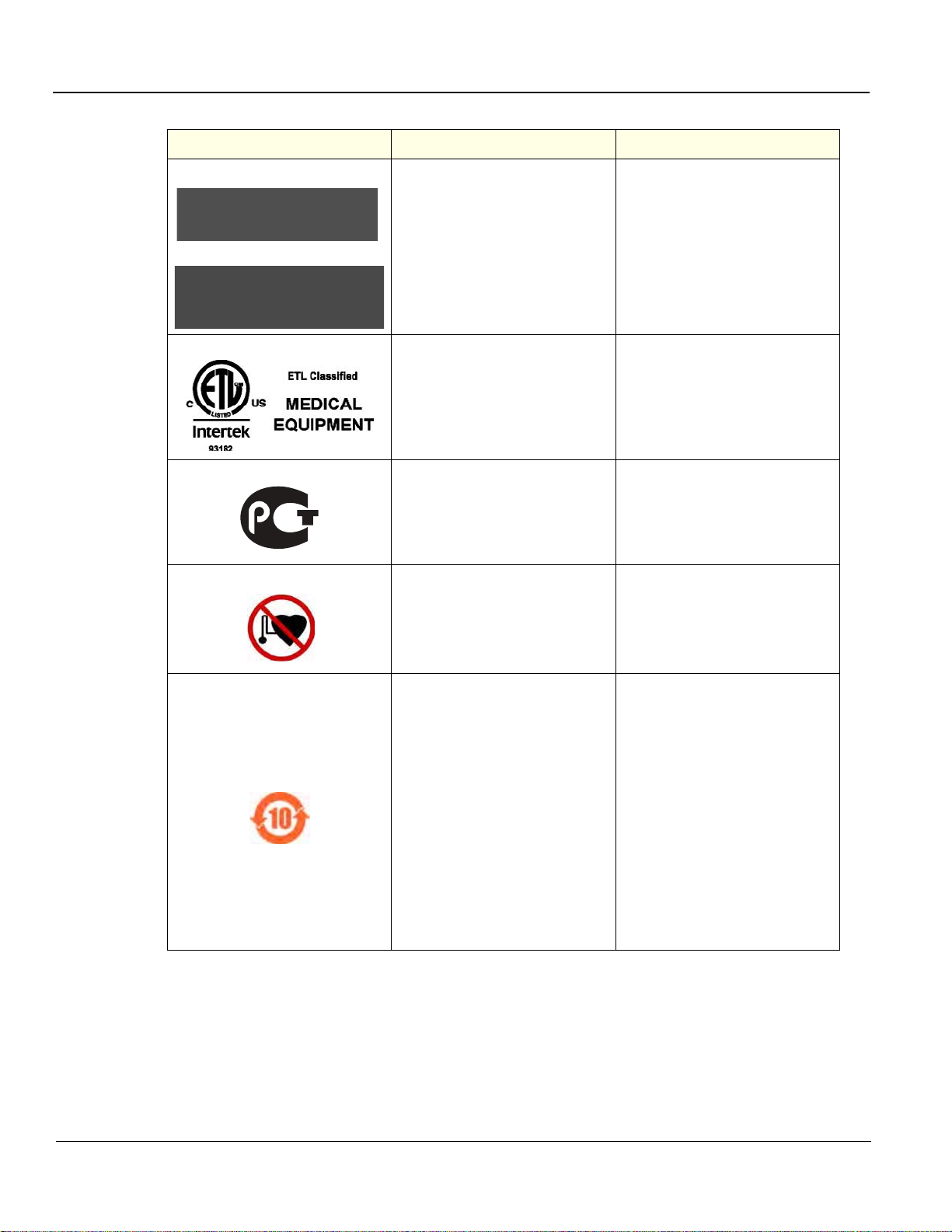
GE HEALTHCARE
DIRECTION 5180263-100, REV 5 LOGIQ E9 Service Manual
Table 1-6 Product icons (Continued) 5 of 6
LABEL/SYMBOL PURPOSE/MEANING LOCATION
This product consists of devices that
may contain mercury, which must be
or
recycled or disposed of in accordance
with local, state, or country laws. (Within
this system, the backlight lamps in the
monitor display, contain mercury.)
Rear of LCD Monitor (inside)
Rear Panel
ETL Listing Mark Monogram
GOST Symbol. Russia Regulatory
Country Clearance.
ISO 7010 - P007
Volume Navigation Pacemaker Warning
Indicates the presence of hazardous
substance(s) above the maximum
concentration value. Maximum
concentration values for electronic
information products, as set by the
People’s Republic of China Electronic
Industry Standard SJ/T11364-2006,
include the hazardous substances of
lead, mercury, hexavalent chromium,
cadmium, polybrominated biphenyl
(PBB), and polybrominated diphenyl
ether (PBDE). “10” indicates the number
of years during which the hazardous
substance(s) will not leak or mutate so
that the use of this product will not result
in any severe environmental pollution,
bodily injury, or damage to any assets.
Rear Panel
Rear Panel
V Nav Transmitter
Probe
1 - 14 Section 1-3 - Important conventio ns
Page 49
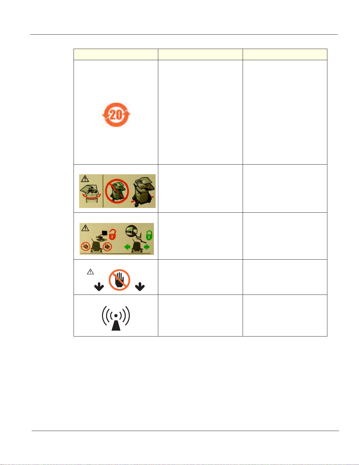
GE HEALTHCARE
DIRECTION 5180263-100, REV 5 LOGIQ E9 Service Manual
Table 1-6 Product icons (Continued) 6 of 6
LABEL/SYMBOL PURPOSE/MEANING LOCATION
Indicates the presence of hazardous
substance(s) above the maximum
concentration value. Maximum
concentration values for electronic
information products, as set by the
People’s Republic of China Electronic
Industry Standard SJ/T11364-2006,
include the hazardous substances of
lead, mercury, hexavalent chromium,
cadmium, polybrominated biphenyl
(PBB), and polybrominated diphenyl
ether (PBDE). “20” indicates the number
of years during which the hazardous
substance(s) will not leak or mutate so
that the use of this product will not result
in any severe environmental pollution,
bodily injury, or damage to any assets.
China Rating Plate
How to lower LCD prior to transport
How to lock Operator Panel prior to
transport
DO NOT place a finger, hand or any
object on the joint of the monitor or
monitor arm to avoid injury when moving
the monitor and monitor arm.
Non-ionizing Electromagnetic Radiation
Label
Rear of the LCD monitor.
Rear of the LCD monitor.
Rear Panel
Chapter 1 Introduction 1 - 15
Page 50

GE HEALTHCARE
DANGER
WARNINGWARNING
WARNINGWARNING
WARNINGWARNING
WARNINGWARNING
WARNINGWARNING
DIRECTION 5180263-100, REV 5 LOGIQ E9 Service Manual
Section 1-4
Safety considerations
1-4-1 Introduction
The following safety precautions must be observed during all phases of operation, service and repair of
this equipment. Failure to comply with these precautions or with specific warnings elsewhere in this
manual, violates safety standards of design, manufacture and intended use of the equipment.
1-4-2 Human safety
• Operating personnel must not remove the system covers.
• Servicing should be performed by authorized personnel only.
Only personnel who have participated in a LOGIQ E9 Training Seminar are authorized to service the
equipment.
DANGEROUS VOLTAGES, CAPABLE OF CAUSING DEATH, ARE PRESENT IN
THIS EQUIPMENT. USE EXTREME CAUTION WHEN HANDLING, TESTING AND
ADJUSTING.
IF THE COVERS ARE REMOVED FROM AN OPERATING LOGIQ E9, SOME METAL
SURFACES MAY BE WARM ENOUGH TO POSE A POTENTIAL HEAT HAZARD IF
TOUCHED, EVEN WHILE IN SHUTDOWN MODE.
BECAUSE OF THE LIMITED ACCESS TO CABINETS AND EQUIPMENT IN THE FIELD,
PLACING PEOPLE IN AWKWARD POSITIONS, GE HAS LIMITED THE LIFTING WEIGHT
FOR ONE PERSON IN THE FIELD TO 16 KG (35 LBS). ANYTHING OVER 16 KG (35 LBS)
REQUIRES 2 PEOPLE.
USE ALL PERSONAL PROTECTION EQUIPMENT (PPE) SUCH AS GLOVES, SAFETY
SHOES, SAFETY GLASSES, AND KNEELING PAD, TO REDUCE THE RISK OF INJUR Y.
EXPLOSION WARNING
DO NOT OPERATE THE EQUIPMENT IN AN EXPLOSIVE ATMOSPHERE.
OPERATION OF ANY ELECTRICAL EQUIPMENT IN SUCH AN ENVIRONMENT
CONSTITUTES A DEFINITE SAFETY HAZARD.
Do Not Substitute Parts or Modify Equipment
Because of the danger of introducing additional hazards, do not install substitute
parts or perform any unauthorized modification of the equipment.
1 - 16 Section 1-4 - Safety considerations
Page 51
GE HEALTHCARE
DIRECTION 5180263-100, REV 5 LOGIQ E9 Service Manual
1-4-2Human safety (cont’d)
WARNINGWARNING
WARNINGWARNING
WARNINGWARNING
WARNINGWARNING
When the top console is in its locked position, the gas shock is compressed and
stores mechanical energy. During normal operation the top console, the weight of
the monitor and the mechanical force of the gas shock are in balance. Take care if/
when you activate this gas shock. Personal injury can occur after the panel is
removed and the shock pressure is released. Take care when you repair the
elevation assembly.
Ensure that the system is turned off and unplugged.
Wait for at least 20 seconds for capacitors to discharge as there are no test points to verify isolation.
The Amber light on the Op Panel On/Off button will turn off.
Beware that the Main Power Supply, Extended Power Shutdown and Back End Processor may be
energized even if the power is turned off when the cord is still plugged into the AC Outlet
Risk of electrical shock, system must be turned off and disconnected from power
source. Cord must be controlled at all times.
discharge as there are no test points to verify isolation. The Amber light on the Op Panel On/Off
button will turn off.
Beware that the Main Power Supply, Extended Power Shutdown and Back End Processor may be
energized even if the power is turned off when the cord is still plugged into the AC Outlet
Wait for at least 20 seconds for capacitors to
Use extreme caution as long as THE LOGIQ E9 is un-stable, not resting on all four
Casters.
WARNINGWARNING
WARNINGWARNING
WARNINGWARNING
WARNINGWARNING
Tilting the console requires two people in order to avoid injury to service personnel
and damage to the equipment.
Use all Personal Protection Equipment (PPE) such as gloves, safety shoes, safety
glasses, and kneeling pad, to reduce the risk of injury.
Beware of possible sharp edges on all mechanical parts. If sharp edges are
encountered, the appropriate PPE should be used to reduce the risk of injury.
Wear all PPE including gloves as indicated in the chemical MSDS.
Chapter 1 Introduction 1 - 17
Page 52

GE HEALTHCARE
WARNINGWARNING
WARNINGWARNING
WARNINGWARNING
WARNINGWARNING
WARNINGWARNING
WARNINGWARNING
CAUTION
CAUTION
CAUTION
DIRECTION 5180263-100, REV 5 LOGIQ E9 Service Manual
1-4-3 Mechanical safety
While the software install procedure is designed to preserve data, you should save any
patient data, images, system setups to a DVD or hardcopy before doing a software
upgrade.
PRIOR TO ELEVATING THE SCANNER, VERIFY THAT THE KEYBOARD IS LOCKED IN
ITS LOWEST POSITION. VERIFY THAT THE FRONT BRAKE IS LOCKED AND THE
SCANNER IS UNABLE TO SWIVEL. VERIFY THAT THE REAR BRAKES ARE IN THE
LOCKED POSITION.
WHEN THE UNIT IS RAISED FOR A REPAIR OR MOVED ALONG ANY INCLINE, USE
EXTREME CAUTION SINCE IT MAY BECOME UNSTABLE AND TIP OVER.
ULTRASOUND PROBES ARE HIGHLY SENSITIVE MEDICAL INSTRUMENTS THAT CAN
EASILY BE DAMAGED BY IMPROPER HANDLING. USE CARE WHEN HANDLING AND
PROTECT FROM DAMAGE WHEN NOT IN USE. DO NOT USE A DAMAGED OR
DEFECTIVE PROBE. FAILURE TO FOLLOW THESE PRECAUTIONS CAN RESULT IN
SERIOUS INJURY AND EQUIPMENT DAMAGE.
REMEMBER: If the front caster swivel lock is engaged for transportation, pressing the
release pedal once disengages the swivel lock. You must depress the release pedal a
second time to engage the brake.
The system should NOT be moved with the Operator I/O Panel extended. Move the
Operator I/O Panel to its centered and locked position. Lower the Operator I/O Panel as
much as possible before moving the system.
BEFORE YOU MOVE OR TRANSPORT THE SYSTEM, MAKE SURE TO LOCK THE LCD
MONITOR ARM FIRMLY AND FLIP DOWN THE MONITOR TO PREVENT DAMAGE TO THE
SYSTEM.
Always lock the Top/Upper Console in its parking (locked) position before moving the scanner
around.
TO AVOID INJURY WHEN YOU MOVE THE LCD MONITOR AND THE MONITOR ARM, DO NOT
PUT YOUR FINGER, HAND, OR OBJECT ON THE JOINT OF THE MONITOR OR THE MONITOR
ARM.
1 - 18 Section 1-4 - Safety considerations
Page 53

GE HEALTHCARE
DIRECTION 5180263-100, REV 5 LOGIQ E9 Service Manual
1-4-3Mechanical safety (cont’d)
CAUTION
CAUTION
CAUTION
CAUTION
LOGIQ E9 WEIGHS 135 KG (298 LB), R3.X AND EARLIER, 140 KG (309 LB), R4.X AND
LATER, OR MORE, DEPENDING ON INSTALLED PERIPHERALS, WHEN READY FOR
USE. CARE MUST BE USED WHEN MOVING IT OR REPLACING ITS PARTS. FAILURE TO
FOLLOW THE PRECAUTIONS LISTED BELOW COULD RESULT IN INJURY,
UNCONTROLLED MOTION AND COSTLY DAMAGE. ALWAYS:
- BE SURE THE PATHWAY IS CLEAR.
- USE SLOW, CAREFUL MOTIONS.
- USE TWO PEOPLE WHEN MOVING ON INCLINES OR LIFTING MORE THAN
16 KG (35 LBS).
TO AVOID INJURY OR DAMAGE TO THE MONITOR, MAKE SURE THERE IS NOTHING WITHIN
RANGE OF THE LCD BEFORE MOVING THE MONITOR AND MONITOR ARM. THIS INCLUDES
PEOPLE AS WELL AS THINGS.
Ensure that nobody touches the console arm/frogleg when moving the Operator Panel.
Use Protective Glasses during drilling, filing and during all other work where eyes need
protection.
CAUTION
CAUTION
NOTICE
Use Safety Shoes when doing work where there is any chance of foot damage.
Use Protective Gloves when drilling and cutting.
Be careful not to pinch any of the cables.
NOTE: Special care should be taken when transporting the unit in a vehicle, see 4-2-14-4 "T ransporting
the unit by vehicle" on page 4-18.
Chapter 1 Introduction 1 - 19
Page 54

GE HEALTHCARE
WARNINGWARNING
DIRECTION 5180263-100, REV 5 LOGIQ E9 Service Manual
1-4-4 Electrical safety
1-4-4-1 Safe practices
Follow these guidelines to minimize shock hazards whenever you are using the scanner:
• The equipment chassis must be connected to an electrical ground.
• The unit is equipped with a three-conductor AC power cable. This must b e plugged into an approved
electrical outlet with safety ground. A separate po we r outle t w ith a 20 am p circuit breaker for 120
VAC for 120V area, 7.5 amp circuit breaker for 220-240 VAC for 220/240V area or 15 amp circuit
breaker for 100 VAC for Japan.
• The power outlet used for this equipment should not be shared with other types of equipment.
• Both the system power cable and the power co nnector must meet international electrical standard s.
Connecting a LOGIQ E9 scanner to the wrong voltage level will most likely destroy it.
1-4-4-2 Probes
Follow these guidelines before connecting a probe to the scanner:
• Inspect the probe prior to each use for damage or degr adation to the:
- housing
- cable strain relief
-lens
- seal
- connector pins
- locking mechanism
• Do not use a damaged or defective probe.
• Never immerse the probe connector or adapter into any liquid.
• The system has more than one type of probe port. Use the appropriate probe port designed for the
probe you are connecting.
Section 1-5
Label locations
Refer to the current revision of the LOGIQ E9 Basic User Manual, 5180374-100, Chapter 2.
1 - 20 Section 1-5 - Label locations
Page 55
GE HEALTHCARE
DANGER
WARNINGWARNING
WARNINGWARNING
WARNINGWARNING
DIRECTION 5180263-100, REV 5 LOGIQ E9 Service Manual
Section 1-6
Dangerous procedure warnings
Warnings, such as the example below, precede potentially dangerous procedures throughout this
manual. Instructions contained in the warnings must be followed.
DANGEROUS VOLTAGES, CAPABLE OF CAUSING DEATH, ARE PRESENT IN
THIS EQUIPMENT. USE EXTREME CAUTION WHEN HANDLING, TESTING AND
ADJUSTING.
IF THE COVERS ARE REMOVED FROM AN OPERATING LOGIQ E9, SOME METAL
SURFACES MAY BE WARM ENOUGH TO POSE A POTENTIAL HEAT HAZARD IF
TOUCHED, EVEN WHILE IN SHUT DOWN MODE.
EXPLOSION WARNING
DO NOT OPERATE THE EQUIPMENT IN AN EXPLOSIVE ATMOSPHERE. OPERATION
OF ANY ELECTRICAL EQUIPMENT IN SUCH AN ENVIRONMENT CONSTITUTES A
DEFINITE SAFETY HAZARD.
DO NOT SUBSTITUTE PARTS OR MODIFY EQUIPMENT.
BECAUSE OF THE DANGER OF INTRODUCING ADDITIONAL HAZARDS, DO NOT
INSTALL SUBSTITUTE PARTS OR PERFORM ANY UNAUTHORIZED MODIFICATION
OF THE EQUIPMENT.
Chapter 1 Introduction 1 - 21
Page 56
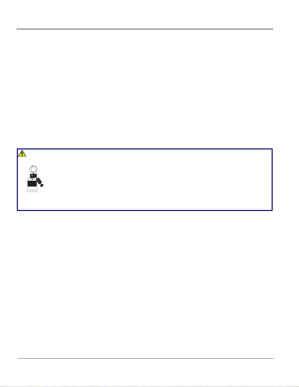
GE HEALTHCARE
NOTICE
Signed
Date
TAG
&
LOCKOUT
DIRECTION 5180263-100, REV 5 LOGIQ E9 Service Manual
Section 1-7
Lockout/Tagout (LOTO) requirements
Follow OSHA Lockout/Tagout requirements (USA) or local Lockout/Tagout requirements by ensuring
you are in total control of the AC power plug at all times during the service process.
To apply Lockout/Tagout:
1.) Plan and prepare for shutdown.
2.) Shutdown the equipment.
3.) Isolate the equipment.
4.) Apply Lockout/Tagout Devices.
5.) Disconnect the Extended Power Shutdown battery at J3 when working in the BEP.
6.) Control all stored and residual energy.
7.) Verify isolation.
All potentially hazardous stored or residual energy is relieved.
Energy Control and Power Lockout for LOGIQ E9
When servicing parts of the system where there is exposure to voltage greater than 30 Volts:
1. Turn off the scanner.
2. Unplug the system.
3. Maintain control of the system power plug.
4. Wait for at least 20 seconds for capacitors to discharge as there are no test points to verify iso lation.
The Amber light on the Op Panel On/Off button will turn off.
5. Disconnect the eps battery at j3 WHEN WORKING IN THE BEP.
Beware that the Main Power Supply, Extended Power Shutdown and Back End Processor may be
energized even if the power is turned off when the cord is still plugged into the AC Outlet.
Section 1-8
Returning/Shipping Probes and Repair Parts
Equipment being returned must be clean and free of blood and other in fectious substances.
GE Healthcare policy states that body fluids must be properly removed from any part or equipment prior
to shipment. GE Healthcare employees, as well as customers, are responsible for ensuring that parts/
equipment have been properly decontaminated prior to shipment. Under no circumstance should a part
or equipment with visible body fluids be taken or shipped from a clinic or site (for example, body coils
or an ultrasound probe).
The purpose of the regulation is to protect employees in the transportation industry, as well as the
people who will receive or open this package.
NOTE:The US Department of Transportation (DOT) has ruled that “items that were saturated and/or
dripping with human blood that are now caked with dried blood; or which were used or intended
for use in patient care” are “regulated medical waste” for tran sporta tion pu rposes and must be
transported as a hazardous material.
1 - 22 Section 1-7 - Lockout/Tagout (LOTO) requirements
Page 57

GE HEALTHCARE
WARNINGWARNING
WARNINGWARNING
DIRECTION 5180263-100, REV 5 LOGIQ E9 Service Manual
Section 1-9
Electromagnetic compatibility (EMC)
1-9-1 What is EMC?
Electromagnetic compatibility describes a level of performance of a device within its electromagnetic
environment. This environment consists of the device itself and its surroundings including other
equipment, power sources and persons with which the device must interface. Inadequate compatibility
results when a susceptible device fails to perform as inte nded due interfer ence from its enviro nment or
when the device produces unacceptable levels of emission to its environmen t. This interference is often
referred to as radio–frequency or electromagnetic interference (RFI/EMI) and can be radiated through
space or conducted over interconnecting power of signal cables. In addition to ele ctromagnetic energy,
EMC also includes possible effects from electrical fields, magnetic fields, electrostatic discharge and
disturbances in the electrical power supply.
1-9-2 Compliance
LOGIQ E9 conforms to all applicable conducted and radiated emission limits and to immunity from
electrostatic discharge, radiated and conducted RF fields, magnetic fields and power line transient
requirements.
Applicable standards are: 47CFR Part 18, IEC60601–1–2:2001.
NOTE: For CE Compliance, it is critical that all covers, screws, shielding, gaskets, mesh, clamps, are
in good condition, installed tightly without skew or stress. Proper installation following all
comments noted in this service manual is required in order to achieve full EMC performance.
1-9-3 Electrostatic discharge (ESD) prevention
DO NOT TOUCH ANY BOARDS WITH INTEGRATED CIRCUITS PRIOR TO TAKING THE
NECESSARY ESD PRECAUTIONS:
1. ALWAYS CONNECT YOURSELF, VIA AN ARM-WRIST STRAP, TO THE ADVISED ESD
CONNECTION POINT LOCATED ON THE REAR OF THE SCANNER (TO THE RIGHT OF
THE POWER CONNECTOR).
2. FOLLOW GENERAL GUIDELINES FOR HANDLING OF ELECTROSTATIC SENSITIVE
EQUIPMENT.
Risk of electrical shock, system must be turned off. Avoid all contact with electrical
contacts, conductors and components. Always use non-conductive handles designed
for the removal and replacement of ESD sensitive parts. All parts that have the potential
for storing energy must be discharged or isolated before making contact.
Chapter 1 Introduction 1 - 23
Page 58

GE HEALTHCARE
DIRECTION 5180263-100, REV 5 LOGIQ E9 Service Manual
Section 1-10
Customer assistance
1-10-1 Contact information
If this equipment does not work as indicated in this service manual or in the user manual, or if you
require additional assistance, please contact the loca l distributor or appropriate support resource, as
listed below.
Before you call, identify the following information, and acquire image (Alt+D) to send to the Customer
Care team:
1.) System ID serial number.
2.) Software version.
3.) Date and time of occurrence.
4.) Sequence of events leading to issue.
5.) Is the issue repeatable?
6.) Imaging mode, probe, preset/application.
7.) Media brand, speed, capacity, type.
8.) Save secondary image capture, cine loop, 4D multi-volume loop.
NOTE: Restart the application before resuming clinical scanning.
Table 1-7 Phone numbers for Customer Assistance
LOCATION PHONE NUMBER
USA
GE Healthcare - GE Medical Systems
Ultrasound & Primary Care Diagnostics, LLC
9900 Innovation Drive
Wauwatosa, WI 53226
Canada 1-800-668-0732
Latin America
Europe
GE Ultraschall Deutschland Gmbh & Co. KG
Beethovenstrasse 239
Postfach 11 05 60, D-42655 Solingen
Germany
Asia (Singapore)
GE Ultrasound Asia
Service Department - Ultrasound
298 Tiong Bahru Road #15-01/06
Central Placa
Singapore 168730
Service: On-site
Service Parts
Application Support
Service
Application Support
Phone: +33 (0) 130-831-300 (General Imaging and Cardiac)
+49 (0) 212-2802-652
Fax: +49 (0) 2122-8024-31
Tel: +65 6291-8528
Fax: +65 6291-7006
1-800-437-1171
1-800-558-2040
1-800-682-5327 or 1-262-524-5698
1-262-524-5300
1-262-524-5698
Japan Support Center
Phone: 81-426-48-2940
Fax: 81-426-48-2905
1 - 24 Section 1-10 - Customer assistance
Page 59

GE HEALTHCARE
DIRECTION 5180263-100, REV 5 LOGIQ E9 Service Manual
1-10-2 System manufacturer
Table 1-8 System manufacturer
MANUFACTURER FAX NUMBER
GE Healthcare - GE Medical Systems Ultrasound and Primary Care Diagnostics, LLC
9900 Innovation Drive
Wauwatosa, WI 53226
USA
Table 1-9 Authorized Representative
AUTHORIZED REPRESENTATIVE TELEPHONE / FAX NUMBER
The location of the CE marking is shown in the Safety chapter of this manual.
414-721-3865
+49 761 45 43 -0 /
+49 761 45 43 -233
Authorized EU Representative European registered place of business:
GE Medical Systems Information Technologies GmbH(GEMS IT GmbH)
Munzinger Strasse 3, D-79111 Freiburg, GERMANY
Chapter 1 Introduction 1 - 25
Page 60

GE HEALTHCARE
DIRECTION 5180263-100, REV 5 LOGIQ E9 Service Manual
This page was intentionally left blank.
1 - 26 Section 1-10 - Customer assistance
Page 61

GE HEALTHCARE
DIRECTION 5180263-100, REV 5 LOGIQ E9 Service Manual
Chapter 2
Site preparations
Section 2-1
Overview
2-1-1 Purpose of this chapter
This chapter provides the information re qu ir ed to plan and prepare for the setup of a LOGIQ E9.
Included are descriptions of the facility and electrical needs to be met by the purchaser of the LOGIQ E9.
Chapter 2 Site preparations 2 - 1
Page 62

GE HEALTHCARE
DIRECTION 5180263-100, REV 5 LOGIQ E9 Service Manual
Section 2-2
General console requirements
2-2-1 Console environmental requirements
2-2-1-1 If the LOGIQ E9 is very cold or hot
When unpacking the device, allow the temperature of the device to stabilize before powering up. The
following table describes guidelines for reaching operational temperatures from storage or transport
temperatures. See: Table 2-1’
Table 2-1 LOGIQ E9 Acclimate Time
o
60 55 50 45 40 35 30 25 20 15 10 5 0 -5 -10 -15 -20 -25 -30 -35 -40
C
o
140 131 122 113 104 95 86 77 68 59 50 41 32 23 14 5 -4 -13 -22 -31 -40
F
Hrs 864200000002468101214161820
2-2-1-2 Environmental specifications
Table 2-2 Environmental Specifications for LOGIQ E9 Scanners
Temperature
Humidity
Pressure 70 - 106 kPa 70 - 106 kPa 70 - 106 kPa
Heat Dissipation
2-2-1-3 Cooling
The cooling requirement for the LOGIQ E9 scanner with LCD and onboard peripherals, is up to 4712
Btu/hr. This figure does not include cooling needed for lights, people, or other equipment in the room.
Each person in the room places an additional 300 Btu/hr demand on the cooling system.
2-2-1-4 Lighting
Bright light is needed for LOGIQ E9 installation, updates and repairs. However, operator and patient
comfort may be optimized if the room light is subdued and indirect. Therefore a combination lighting
system (dim/bright) is recommended. Keep in mind that lighting controls and dimmers can be a source
of EMI which could degrade image quality. These con tr ols should be selected to minimize possible
interference.
Operational Storage Transport (< 16 hrs.)
10º - 35º C
(50º - 96º F)
30% - 80%
non-condensing
4712 Btu/hour “ “
-10º - 50º C
(-14º - 122º F)
30% - 80%
non-condensing
-10º - 50º C
(-14º - 122º F)
30% - 80%
non-condensing
2 - 2 Section 2-2 - General console requirements
Page 63

GE HEALTHCARE
DIRECTION 5180263-100, REV 5 LOGIQ E9 Service Manual
2-2-2 Electrical requirements
2-2-2-1 General requirements
NOTE: GE Healthcare requires a dedicated power and ground for the proper operation of its Ultrasound
equipment. This dedicated power shall originate at the last distribution panel before the LOGIQ E9.
The LOGIQ E9 will function on Voltages from 100-240 Volts and 50 or 60 Hz. However, if using 220 volt
power, then a center tapped power source is required.
Sites with a mains power system with defined Neutral and Live:
The dedicated line shall consist of one phase, a neutral (not shared with any other circuit), and a full
size ground wire from the distribution panel to the LOGIQ E9 outlet.
Sites with a mains power system without a defined Neutral:
The dedicated line shall consist of one phase (two lines), not shared with any other circui t, and a full
size ground wire from the distribution panel to the LOGIQ E9 outlet.
NOTE: Please note that image artifacts can occur, if at any time within the facility, the ground from the
main facility's incoming power source to the Ultrasound unit is only a conduit.
2-2-2-2 Electrical requirements for LOGIQ E9
In the table below, the electrical specifications for LOGIQ E9 include LCD and on board peripherals.
Table 2-3 Electrical specifications for the LOGIQ E9
POWER
PART NUMBER DESCRIPTION VOLTAGE TOLERANCES
5205000-x
LOGIQ E9, 100-240 VAC 100-240 VAC +/-10% 1100 W 50/60 Hz
CONSUMPTION FREQUENCY
The current drain varies, depending on the mains voltage.
• At 230 VAC, the current may be up to 7.5 A.
• At 100 VAC, the current may be up to 12 A.
2-2-2-3 Inrush current
During power on, an inrush circuit prevents the current from increasing above the stated values.
Table 2-4 Inrush current at different mains voltages
VOLTAGE 50 Hz 60 Hz
90 VAC 13 A 12 A
110 VAC 9 A 11 A
220 VAC 5.5 A 6 A
264 VAC 6 A 5 A
Chapter 2 Site preparations 2 - 3
Page 64

GE HEALTHCARE
CAUTION
DIRECTION 5180263-100, REV 5 LOGIQ E9 Service Manual
2-2-2-4 Site circuit breaker
POWER OUTAGE MAY OCCUR.
THE LOGIQ E9 SCANNER REQUIRES A DEDICATED SINGLE BRANCH CIRCUIT. TO AVOID
CIRCUIT OVERLOAD AND POSSIBLE LOSS OF CRITICAL CARE EQUIPMENT, MAKE SURE
YOU DO NOT HAVE ANY OTHER EQUIPMENT OPERATING ON THE SAME CIRCUIT.
It is recommended that the branch circuit breaker for the LOGIQ E9 be readily accessible.
2-2-2-5 Site power outlets
A dedicated AC power outlet must be within reach of the LOGIQ E9 without extension cords. Other
outlets adequate for the external peripherals, medical and test equipment needed to support this
LOGIQ E9 must also be present within 1 m (3.2 ft.) of the LOGIQ E9. Electrical installation must meet
all current local, state, and national electrical codes.
2-2-2-6 LOGIQ E9 power plug
If the LOGIQ E9 arrives without a power plug, or wit h the wron g plug, you must conta ct your GE dealer
or the installation engineer must supply what is locally required.
2-2-2-7 Power stability requirements
Voltage drop-out
Max 10 ms.
Power transients (all applications)
Less than 25% of nominal peak voltage for less than 1 millisecond for any type of transient, including
line frequency, synchronous, asynchronous, or aperiodic transients.
2 - 4 Section 2-2 - General console requirements
Page 65

GE HEALTHCARE
DIRECTION 5180263-100, REV 5 LOGIQ E9 Service Manual
2-2-3 EMI limitations
Ultrasound machines are susceptible to Electromagnetic Interference (EMI) from radio frequencies,
magnetic fields, and transients in the air or wiri ng. Ultrasound machines also generate EMI. The L OGIQ
E9 complies with limits as stated on the EMC label. However there is no guarantee that interference will
not occur in a particular installation.
Possible EMI sources should be identified before the LOGIQ E9 is installed.
Electrical and electronic equipment may produce EMI unintentionally as the result of a defect. These
sources include:
• medical lasers,
• scanners,
• cauterizing guns,
•computers,
•monitors,
• fans,
• gel warmers,
• microwave ovens,
• light dimmers
• portable phones.
The presence of a broadcast station or broadcast van may also cause interference.
See: Table 2-5 on page 2-5 for EMI Prevention tips.
Table 2-5 EMI prevention/abatement
EMI RULE DETAILS
Be aware of RF sources
Ground the LOGIQ E9
Replace all screws, RF
gaskets, covers, cores
Replace broken RF
gaskets
Do not place labels where
RF gaskets touch metal
Use GE specified
harnesses and peripherals
Take care with cellular
phones
Keep the LOGIQ E9 at least 5 meters or 15 feet away from other EMI sources. Special
shielding may be required to eliminate interference problems caused by high frequency, high
powered radio or video broadcast signals.
Poor grounding is the most likely reason a LOGIQ E9 will have noisy images. Check grounding
of the power cord and power outlet.
After you finish repairing or updating the LOGIQ E9, replace all covers and tighten all screws.
Any cable with an external connection requires a magnet wrap at each end. Install the Card
Rack cover over the Card Rack. Loose or missing covers or RF gaskets allow radio
frequencies to interfere with the ultrasound signals.
If more than 20% or a pair of the fingers on an RF gasket are broken, replace the gasket. Do
not turn on the LOGIQ E9 until any loose metallic part is removed.
Never place a label where RF gaskets meet the LOGIQ E9. Otherwise, the gap created will
permit RF leakage. Or, if a label has been found in such a position, move the label.
The interconnect cables are grounded and require ferrite beads and other shielding. Also,
cable length, material, and routing are all important; do not change from what is specified.
Cellular phones may transmit a 5 V/m signal; that could cause image artifacts.
Properly dress peripheral
cables
Do not allow cables to lie across the top of the Card Rack or hang out of the peripheral bays.
Loop the excess length for peripheral cables inside the peripheral bays. Attach the LCD cables
to the frame.
Chapter 2 Site preparations 2 - 5
Page 66
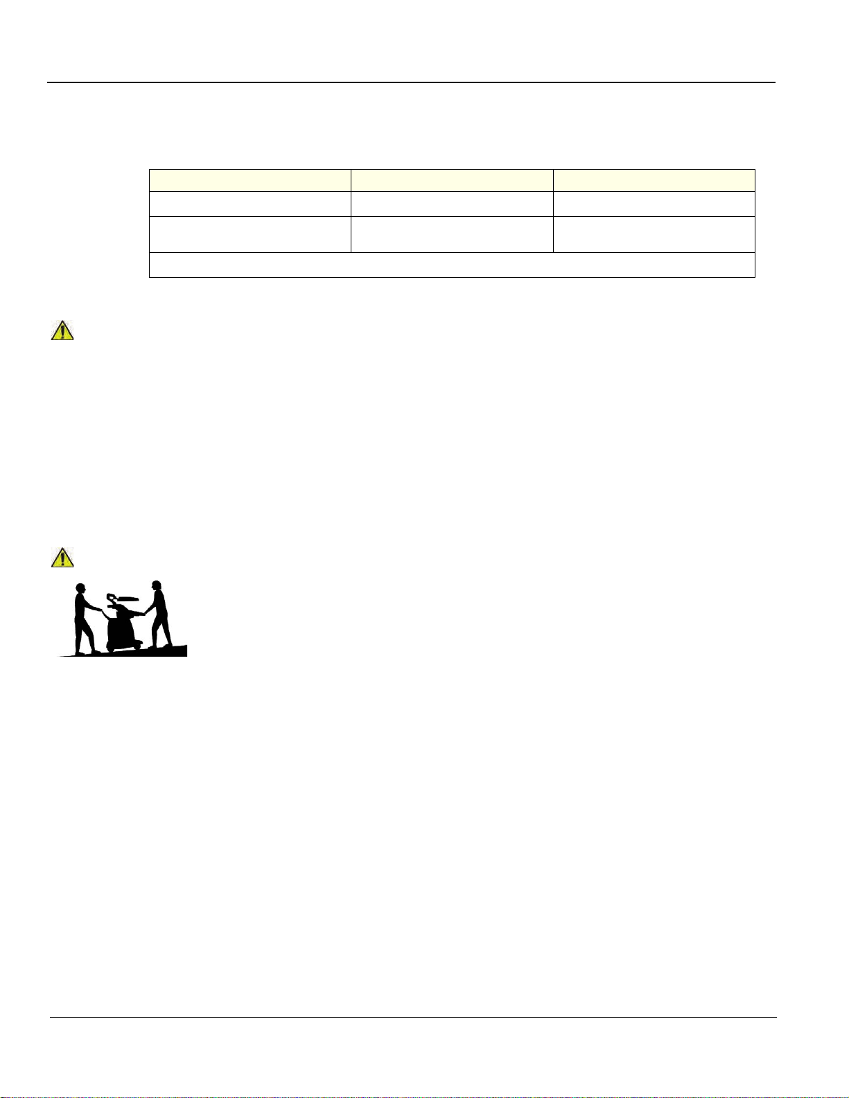
GE HEALTHCARE
NOTICE
CAUTION
DIRECTION 5180263-100, REV 5 LOGIQ E9 Service Manual
2-2-4 Probes environmental requirements
Table 2-6 Environmental Requirements - Probes
Standard Probes 4D Probes
Operation:
Storage:
Temperatures in degrees Celsius (
SYSTEMS AND ELECTRONIC PROBES ARE DESIGNED FOR STORAGE TEMPERATURES OF
-10 TO +50 degrees C. or +60 degrees C, DEPENDING ON THE TYPE OF PROBE. WHEN
EXPOSED TO LARGE TEMPERATURE VARIATIONS, THE PRODUCT SHOULD BE KEPT IN
ROOM TEMPERATURE FOR 10 HOURS BEFORE USE.
Refer to the Table in section 2-2-1-1 on page 2-2 to determine the needed settlement time.
o
10
to 40o C (50 to 104 ºF) 18o to 40o C (64.4 to 104 ºF)
-10° to 60° C (14 to 140 ºF)
-10° to 60° C (14 to 140 ºF)
o
C) conversion to degrees F: (oF) = (oC * 9/5) + 32
o
to 50 o C (14 to 122 ºF)
-10
2-2-5 Time and manpower requirements
Site preparation takes time. Begin Pre-installation checks as soon as possible, if possible, six weeks
before delivery, to allow enough time to make any changes.
HAVE TWO PEOPLE AVAILABLE TO DELIVER AND UNPACK THE LOGIQ E9.
ATTEMPTS TO MOVE THE LOGIQ E9 CONSIDERABLE DISTANCES OR ON AN INCLINE BY ONE
PERSON COULD RESULT IN INJURY OR DAMAGE OR BOTH.
2 - 6 Section 2-2 - General console requirements
Page 67

GE HEALTHCARE
DIRECTION 5180263-100, REV 5 LOGIQ E9 Service Manual
Section 2-3
Facility needs
2-3-1 Purchaser responsibilities
The work and materials needed to prepare the site is the responsibility of the purchaser. Delay,
confusion, and waste of manpower can be avoided by completing pre- installatio n work before delivery.
Purchaser responsibility includes:
• Procuring the materials required.
• Completing the preparations before de liver y of th e LO GI Q E9.
• Paying the costs for any alterations and modifications not specifically provided in the sales contract.
NOTE: All electrical installations that are preliminary to the positioning of the equipment at the site
prepared for the equipment must be performed by licensed electrical contractors. Other
connections between pieces of electrical equipment, calibrations, and testing must also be
performed by qualified personnel. The products involved (and the accompanying electrical
installations) are highly sophisticated and special engineering competence is required. All
electrical work on these products must comply with the requirements of applicable electrical
codes. The purchaser of GE equipment must only utilize qualified personnel to perform
electrical servicing on the equipment.
The desire to use a non–listed or customer provided product or to place an approved product further
from the LOGIQ E9 than the interface kit allows, presents challeng es to the installa tion team. To avoid
delays during installation, such variances should be m ade known to the individ uals or group performing
the installation at the earliest possible date (preferably prior to the purchase).
The ultrasound suite must be clean prior to delivery of the machine. Carpet is not recommended
because it collects dust and creates static. Potential sources of EMI (electromagnetic interference)
should also be investigated before delivery. Dirt, static, and EMI can negatively impact LOGIQ E9
reliability.
Chapter 2 Site preparations 2 - 7
Page 68

GE HEALTHCARE
DIRECTION 5180263-100, REV 5 LOGIQ E9 Service Manual
2-3-2 Required facility needs
NOTE: GE Healthcare requires a dedicated power and ground for the proper operation of its Ultrasound
equipment. This dedicated power shall originate at the last distribution panel before the system.
The LOGIQ E9 will function on Voltages from 100-240 Volts and 50 or 60 Hz. However, if using 220 volt
power, then a center tapped power source is required.
Sites with a mains power system with defined Neutral and Live:
The dedicated line shall consist of one phase, a neutral (not shared with any other circuit), and a full
size ground wire from the distribution panel to the Ultrasound outlet.
Sites with a mains power system without a defined Neutral:
The dedicated line shall consist of one phase (two lines), not shared with any other circuit, and a full
size ground wire from the distribution panel to the Ultrasound outlet.
• Dedicated single branch power outlet of adequate amperage (see: Table 2-5 on page 2-5) meeting
all local and national codes which is located less than 2.5 m (8 ft.) from the LOGIQ E9’s proposed
location
• Door opening is at least 76 cm (30 in) wide.
• Proposed location for LOGIQ E9 is at least 0.46 m (18 inches) from the wall or objects for cooling.
• Power outlet and place for any external peripheral are within 2 m (6.5 ft.) of each other with
peripheral within 1 m (3.2 ft.) of the LOGIQ E9 to connect cables.
• Power outlets for other medical equipment and gel warmer.
• Power outlets for test equipment within 1 m (3.2 ft.) of LOGIQ E9.
• Clean and protected space to store transducers (in their cases or on a rack).
• Material to safely clean probes (done with a plastic container, never metal).
2 - 8 Section 2-3 - Facility needs
Page 69
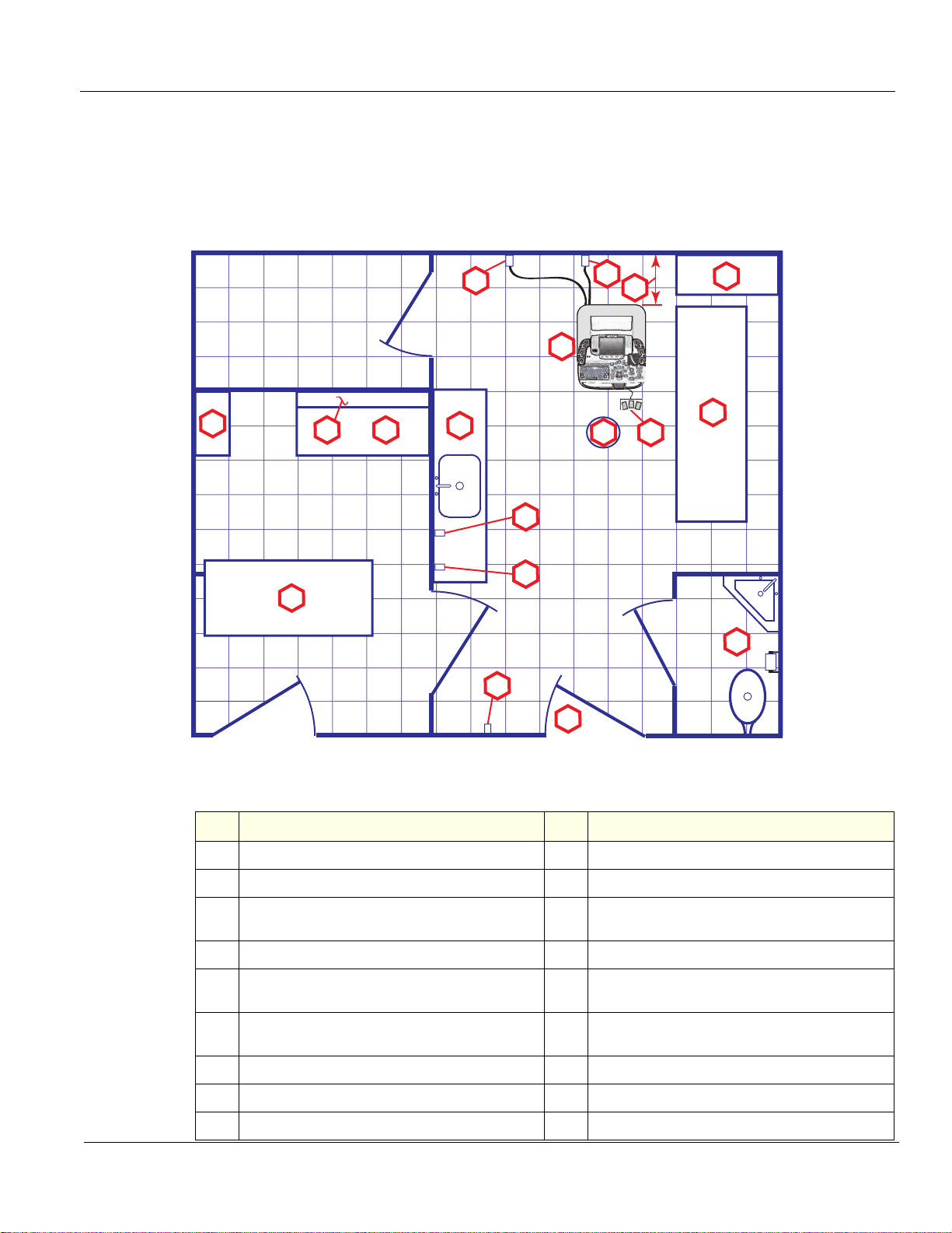
GE HEALTHCARE
DIRECTION 5180263-100, REV 5 LOGIQ E9 Service Manual
2-3-3 Desirable features
In addition to the Floor Plan Suggestions shown in Figure 2-1 and Figure 2-2, a nearby waiting room and a Receptacle for Bio–hazardous Waste,
like used probe sheaths is suggested. Grid represents 305 x 305 mm (1 x 1 foot).
2-3-4 Minimal floor plan suggestions
Figure 2-1 Floor Plan Suggestion 4.27 x 5.18 m (14 x 17 foot)
10
2
3
4
5
11
12
121
2
9
Elasto
13
YY
PWPW
XX
ZZ
CW
MM
CFCF
Body Pattern
Body Pattern
ZoomZoom
Ellipse
Ellipse
BB
3D/4D
CommentComment
AutoAut o
LL
RR
ClearClear
14
15
16
8
7
1
17
6
18
Floor Plan Suggestion 4.27 x 5.18 m (14 x 17 foot) Key
Item Description Item Description
1.
Secretaries or Doctors Desk
3.
Film Viewer
5.
Counter Top and Sink with hot and cold water
7.
Emergency Oxygen
9.
LOGIQ E9
11.
Network Interface
13.
Stool
15.
Storage for Linens and Equipment
17.
Lavatory and Dressing Room
2.
File Cabinet
4.
Counter Top
Overhead Lights Dimmer - Dual Level Lighting (bright
6.
and dim)
8.
Suction Line
Dedicated Power Outlet - Circuit Breaker protected and
10.
easily accessible
457 mm (18 inches) distance of LOGIQ E9 from wall or
12.
objects
14.
Footswitch
16.
Examination Table – 1930 x 610 mm (76 x 24 inches)
18.
Door – at least 762 mm (30 inches)
Chapter 2 Site preparations 2 - 9
Page 70
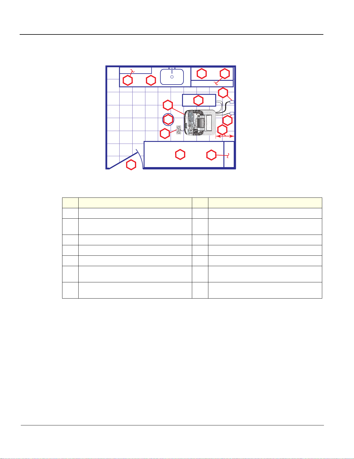
GE HEALTHCARE
DIRECTION 5180263-100, REV 5 LOGIQ E9 Service Manual
2-3-4Minimal floor plan suggestions (cont’d)
Figure 2-2 Floor Plan Suggestion 2.44 x 3.05 m (8 x 10 foot)
4
2
3
5
11
10
9
Elasto
121
8
7
6
2
CommentComment
ClearClear
MM
CW
XX
Body Pattern
Body Pattern
Ellipse
Ellipse
PWPW
YY
ee
ZoomZoom
3D/4D
CFCF
ZZ
LL
BB
RR
AutoAut o
12
13
14
1
Floor Plan Suggestion 2.44 x 3.05 m (8 x 10 foot) Key
Item Description Item Description
1.
Door – at least 762 mm (30 inches)
Counter Top, Sink with hot and cold water and Supplies
3.
Storage
5.
Probes/Supplies
2.
Film Viewer
4.
Linen Supply
6.
Examination Table – 1930 x 610 mm (76 x 24 inches)
7.
Footswitch
9.
LOGIQ E9
Dedicated Power Outlet - Circuit Breaker protected and
11.
easily accessible
457 mm (18 inches) distance of LOGIQ E9 from wall or
13.
objects
8.
Stool
10.
External Peripherals
12.
Network Interface
14.
GE Cabinet for Software and Manuals
2 - 10 Section 2-3 - Facility needs
Page 71

GE HEALTHCARE
DIRECTION 5180263-100, REV 5 LOGIQ E9 Service Manual
2-3-5 Networking setup requirements
2-3-5-1 Stand alone scanner (without network connection)
None.
2-3-5-2 Scanner connected to hospital’s network
Supported networks:
• 10/100/1000 Mbps Ethernet network connection
• Up to 300 Mbps WLAN (option)
2-3-5-3 InSite Requirements
Need internet access available to be able to connect to Insite ExC.
2-3-5-4 Purpose of the DICOM network function
DICOM services provide the operator with clinically useful features for moving images and patient
information over a hospital network. Examples of DICOM services include the transfer of images to
workstations for viewing or transferring images to remote prin ters. As an added benefit, transferring
images in this manner frees up the on-board LCD and peripherals, enabling viewing to be done while
scanning continues. With DICOM, images can be archived, stor ed , and r etrie ve d faster, easie r, a nd at
a lower cost.
2-3-5-5 DICOM option setup requirements
To configure the LOGIQ E9 to work with other network connections, the site’s network administrator
must provide information to complete the form in Figure 2-3 "Worksheet for DICOM Network
Information" on page 2-12. Ensure that there ar e no spa ces in any field of the form.
Entries must include:
• A host name, local port number, AE Title, IP address and Net Mask for the LOGIQ E9.
• The IP addresses for the default gateway and other routers at the site for ROUTING
INFORMATION.
• The host name, IP address, port and AE Title for each device the site wants connected to the
LOGIQ E9
revision of the device, is also included. This information may be useful for troubleshooting.
For connectivity setup information, refer to the current revision of the LOGIQ E9 Basic User Manual.
for DICOM APPLICATION INFORMATION. A field for the make (manufacturer) and the
Chapter 2 Site preparations 2 - 11
Page 72
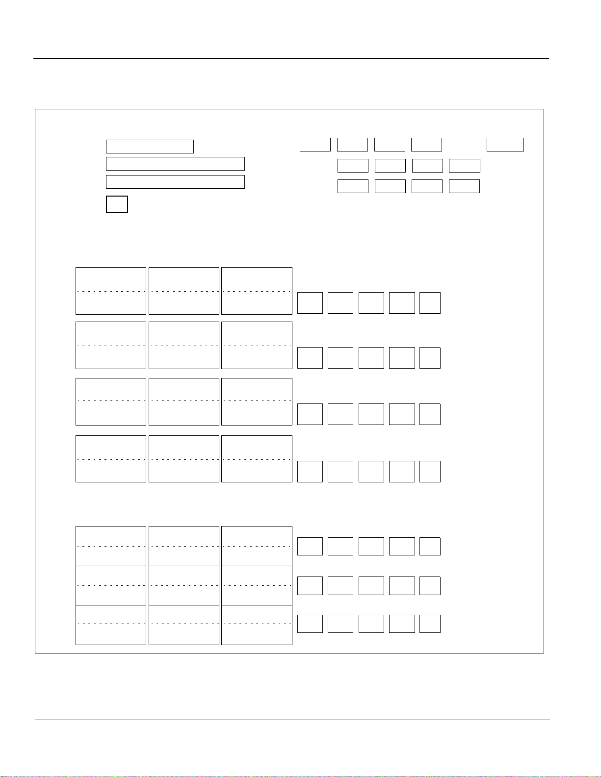
GE HEALTHCARE
LOGIQ E9
Host Name
AE Title
Local Port
IP Address
Net Mask
...
...
...
Default Gateway
DICOM APPLICATION
NAME
Store 2
Store 3
Store 1
MAKE/ IP PORTAE TITLE
DICOM
Print
Storage
Commit
DICOM
MPPS
Worklist
...
...
...
...
...
...
...
Network
Speed
Associated
Storage AE
_____________
__Raw Data
__Allow Multiframe
__Structured
Reporting
Compression_______
__Raw Data
__Allow Multiframe
__Structured
Reporting
Compression_______
__Raw Data
__Allow Multiframe
__Structured
Reporting
Compression_______
Vendor: ___________
Print Size: _________
Medium: ___________
Copies: ___________
Orientation: ________
Color ______________
OTHER
CONFIGURATION
DHCP
DIRECTION 5180263-100, REV 5 LOGIQ E9 Service Manual
2-3-5-5 DICOM option setup requirements (cont’d)
Figure 2-3 Worksheet for DICOM Network Information
2 - 12 Section 2-3 - Facility needs
Page 73

GE HEALTHCARE
DIRECTION 5180263-100, REV 5 LOGIQ E9 Service Manual
Chapter 3
LOGIQ E9 Setup
Section 3-1
Overview
3-1-1 Purpose of this chapter
This chapter contains information needed to set up the LOGIQ E9. Included is a procedure that
describes how to receive and unpack the equipment and how to file a damage or loss claim.
How to prepare the facility and unit of the actual setup, and how to check and test the unit, probes, and
external peripherals for electrical safety are included in this procedure.
Chapter 3 LOGIQ E9 Setup 3 - 1
Page 74

GE HEALTHCARE
DANGER
CAUTION
CAUTION
CAUTION
DIRECTION 5180263-100, REV 5 LOGIQ E9 Service Manual
Section 3-2
Setup reminders
3-2-1 Average setup time
Table 3-1 Average setup time
DESCRIPTION
UNPACKING THE LOGIQ E9 0.5 HOUR
SET UP LOGIQ E9 WO/OPTIONS 4 HOURS DEPENDENT ON THE CONFIGURATION
DICOM NETWORK CONFIGURATION 2 HOURS OR MORE DEPENDENT ON THE CONFIGURATION
INSTALL INSITE / ILINK 0.5 HOUR
3-2-2 Setup warnings
WHEN USING ANY TEST INSTRUMENT THAT IS CAPABLE OF OPENING THE
AC GROUND LINE (I.E., METER’S GROUND SWITCH IS OPEN), DON’T TOUCH
THE UNIT!
TO PREVENT ELECTRICAL SHOCK, CONNECT THE UNIT TO A PROPERLY GROUNDED
POWER OUTLET. DO NOT USE A THREE TO TWO PRONG ADAPTER. THIS DEFEATS SAFETY
GROUNDING.
DO NOT WEAR THE ESD WRIST STRAP WHEN YOU WORK ON LIVE CIRCUITS AND MORE
THAN 30 V PEAK IS PRESENT.
AVERAGE SETUP
TIME
COMMENTS
DO NOT OPERATE THIS UNIT UNLESS ALL BOARD COVERS AND FRAME PANELS ARE
SECURELY IN PLACE. LOGIQ E9 PERFORMANCE AND COOLING REQUIRE THIS.
If the unit is very cold or hot, allow the temperature of the device to stabilize before powering up. The
following table describes guidelines for reaching operational temperatures from storage or transport
temperatures. See: 2-2-2 "Console environmental requirements" on page 2-2.
3 - 2 Section 3-2 - Setup reminders
Page 75

GE HEALTHCARE
DIRECTION 5180263-100, REV 5 LOGIQ E9 Service Manual
3-2-2Setup warnings (cont’d)
CAUTION
CAUTION
OPERATOR MANUAL(S)
THE USER MANUAL(S) SHOULD BE FULLY READ AND UNDERSTOOD BEFORE OPERATING
THE LOGIQ E9 AND KEPT NEAR THE UNIT FOR QUICK REFERENCE.
ACOUSTIC OUTPUT HAZARD
ALTHOUGH THE ULTRASOUND ENERGY TRANSMITTED FROM THE LOGIQ E9 PROBE IS
WITHIN AIUM/NEMA STANDARDS, AVOID UNNECESSARY EXPOSURE. ULTRASOUND
ENERGY CAN PRODUCE HEAT AND MECHANICAL DAMAGE.
Chapter 3 LOGIQ E9 Setup 3 - 3
Page 76

GE HEALTHCARE
CAUTION
CAUTION
DIRECTION 5180263-100, REV 5 LOGIQ E9 Service Manual
Section 3-3
Receiving and unpacking the equipment
3-3-1 Purpose of this section
This section describes how to receive and unpack LOGIQ E9.
3-3-2 Receiving and unpacking warnings
TWO PEOPLE ARE NEEDED TO UNPACK THE UNIT BECAUSE OF ITS WEIGHT.
ATTEMPTS TO MOVE THE UNIT CONSIDERABLE DISTANCES OR ON AN INCLINE BY
ONE PERSON COULD RESULT IN INJURY OR DAMAGE OR BOTH.
TWO PEOPLE ARE REQUIRED WHENEVER A PART WEIGHING 16 KG (35 LBS) OR
MORE MUST BE LIFTED.
REMEMBER TO USE RELEVANT PERSONAL PROTECTING EQUIPMENT (PPE) DURING
PACKING/UNPACKING. CHECK WITH YOUR LOCAL EHS REPRESENTATIVE.
3 - 4 Section 3-3 - Receiving and unpacking the equipment
Page 77

GE HEALTHCARE
DIRECTION 5180263-100, REV 5 LOGIQ E9 Service Manual
3-3-3 Receiving the LOGIQ E9
3-3-3-1 Overview
Improper handling during transportation may harm the equipment inside the package even if the
package itself is undamaged.
3-3-3-2 Examine package
Examine package closely at time of delivery.
3-3-3-3 Damage in transportation
Follow this procedure if damage is apparent:
Table 3-2 Damage in transportation
STEP TASK
1.
2.
Write “Damage In Shipment” on ALL copies of the freight or express bill BEFORE delivery is accepted or “signed
for“ by a GE representative or hospital receiving agent.
Report the damage to the carrier.
• Whether noted or concealed, damage MUST be repor ted to the carrier immediately upon discovery, or in
any event, within 14 days after receipt, and the contents and containers held for inspection by the carrier.
• A transportation company w ill not pay a claim for damage if an inspection is not requested within this 14
day period.
Chapter 3 LOGIQ E9 Setup 3 - 5
Page 78

GE HEALTHCARE
DIRECTION 5180263-100, REV 5 LOGIQ E9 Service Manual
3-3-4 The Tilt and Shock indicators
3-3-4-1 Overview
Improper handling during transportation may harm the equipment inside the package even if the
package itself is undamaged.
To make it easier to detect if the handling during transportation has bee n improper, a Tilt or TIPNTELL
indicator and a Shock indicator have been attached to the transportation box.
3-3-4-2 Position of the Tilt or TipNTell and Shock indicat ors
The Tilt and Shock indicators have been attached to the side of the transportation box.
Figure 3-1 Tilt and Shock indicators
Figure 3-2 TIPNTELL indicator and Label
NOTE: Before cutting the straps, check the Tilt or TIPNTELL and Shock indicators to make sure they
have not been triggered. If triggered, report it to the carrier. If not, then cut the straps around
the crate.
3 - 6 Section 3-3 - Receiving and unpacking the equipment
Page 79

GE HEALTHCARE
DIRECTION 5180263-100, REV 5 LOGIQ E9 Service Manual
3-3-4-3 LOGIQ E9 Transportation Box Label
The LOGIQ E9 Transportation Box Label is located on the transportation box.
Figure 3-3 LOGIQ E9 Transportation Box Labeling
SYMBOL DEFINITION/COMMENTS SYMBOL DEFINITION/COMMENTS
RECYCLING
Recyclable Wood
or
RECYCLING
China Specific
TOP,. UPRIGHT - Transportation
and Storage
KEEP DRY
(protect from moisture)
FRAGILE, Handle with Care
DO NOT STACK
Chapter 3 LOGIQ E9 Setup 3 - 7
Page 80
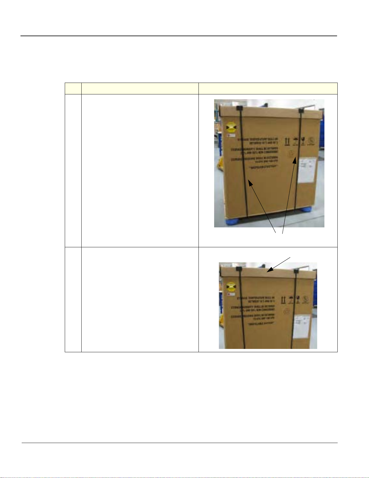
GE HEALTHCARE
1
2
DIRECTION 5180263-100, REV 5 LOGIQ E9 Service Manual
3-3-5 Unpacking the LOGIQ E9
The instruction manual describes the best method for unpacking the LOGIQ E9 ultrasound scanning
unit.
Table 3-3 Uncrating Instructions
Steps Corresponding Graphic
1.
Before cutting the straps, check Shock and
Tilt Tags to make sure they have not been
triggered. If damaged, report it to the
carrier. If not, then cut the straps around the
crate.
2.
Remove the top cover.
3 - 8 Section 3-3 - Receiving and unpacking the equipment
Page 81
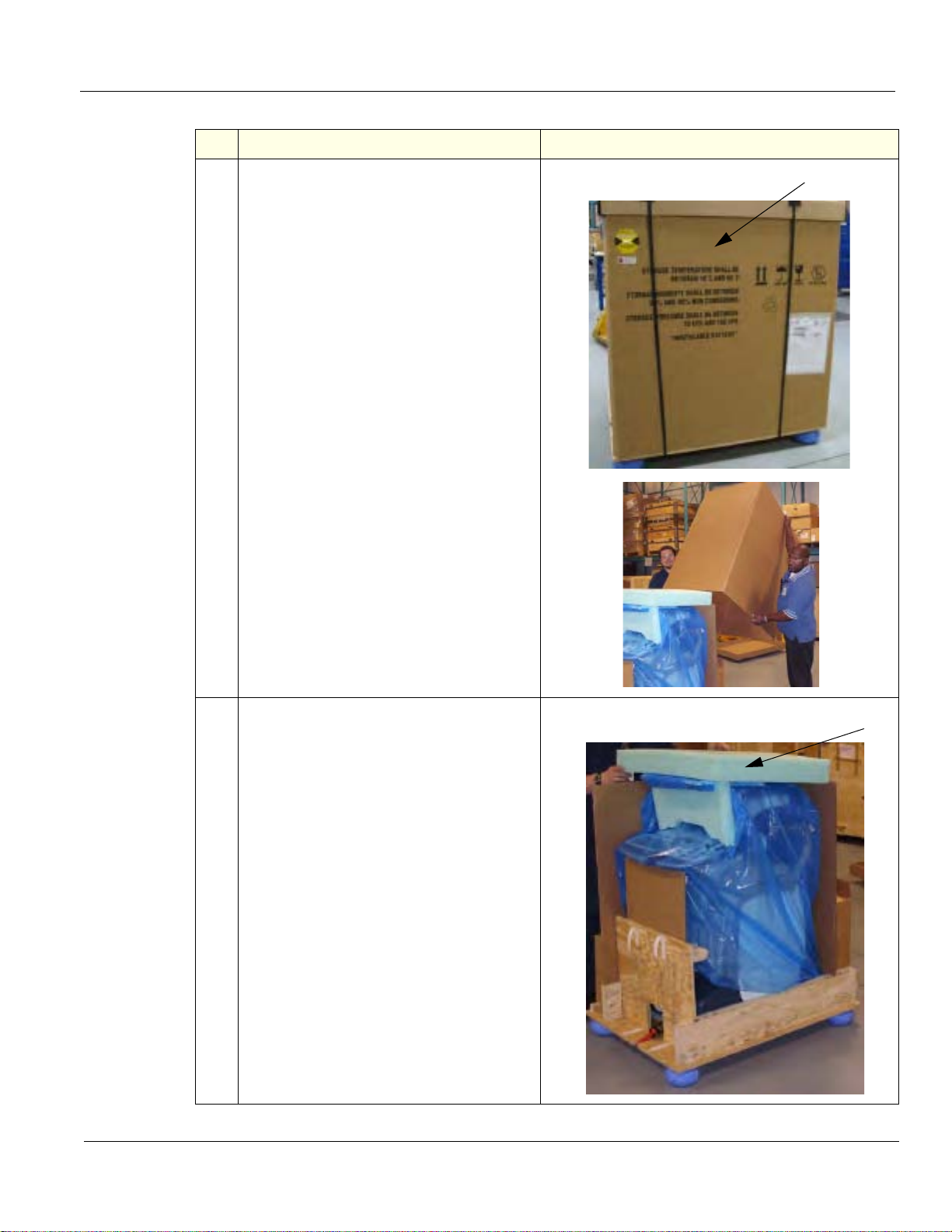
GE HEALTHCARE
3
4
DIRECTION 5180263-100, REV 5 LOGIQ E9 Service Manual
Table 3-3 Uncrating Instructions (Continued)
Steps Corresponding Graphic
3.
Remove the outside shipping box.
Note: Two people are recommended for
performing this step.
4.
Remove the LCD foam.
Chapter 3 LOGIQ E9 Setup 3 - 9
Page 82
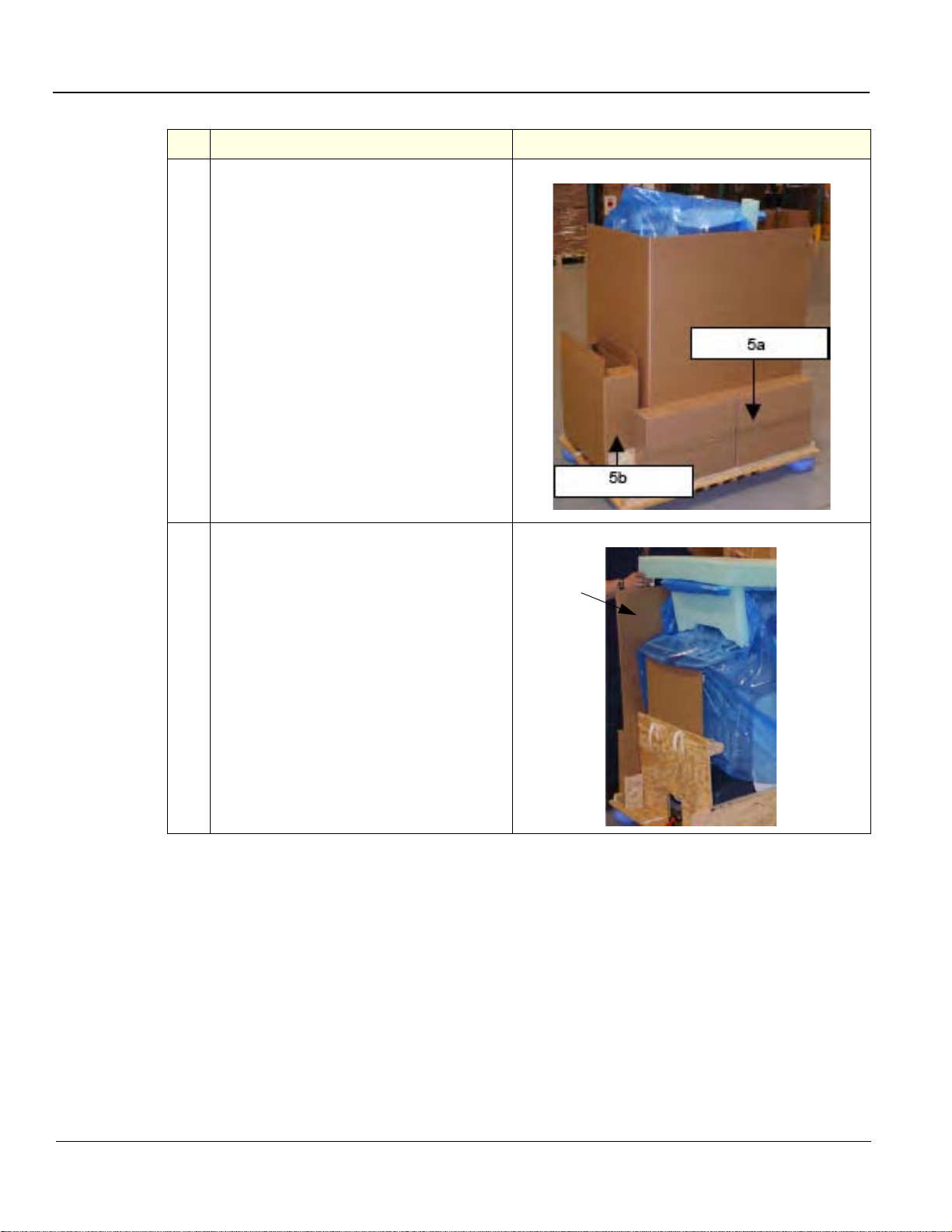
GE HEALTHCARE
6
DIRECTION 5180263-100, REV 5 LOGIQ E9 Service Manual
Table 3-3 Uncrating Instructions (Continued)
Steps Corresponding Graphic
5.
Remove the a) Probes and b) accessory
boxes.
6.
Remove the L-shaped Cardboard divider.
Note: Use special care when removing the
divider.
3 - 10 Section 3-3 - Receiving and unpacking the equipment
Page 83
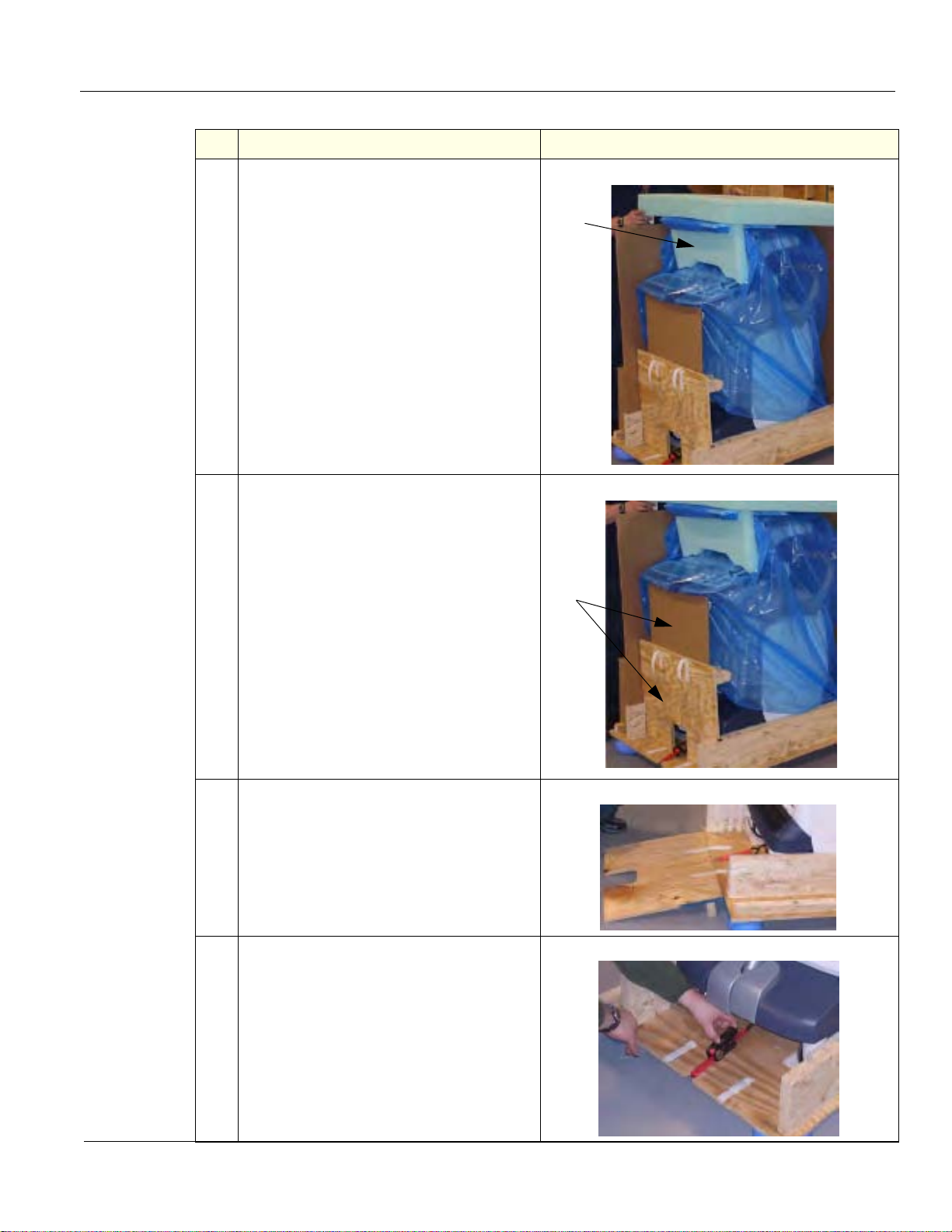
GE HEALTHCARE
7
8
DIRECTION 5180263-100, REV 5 LOGIQ E9 Service Manual
Table 3-3 Uncrating Instructions (Continued)
Steps Corresponding Graphic
7.
Remove the OP panel foam placed
between the monitor and probe holder s.
8.
Remove the lower OP panel brace placed
between the lower OP panel and the
wooden ramp, by moving upward and back.
Remove the wooden ramp.
9.
Attach the wooden ramp to the Pallet Base
with Velcro on the rear side of the
LOGIQ E9.
10.
Loosen the tie-down strap at the front of the
LOGIQ E9. Push the brass piece to pull
back handle, then push brass piece to
loosen strap.
Chapter 3 LOGIQ E9 Setup 3 - 11
Page 84
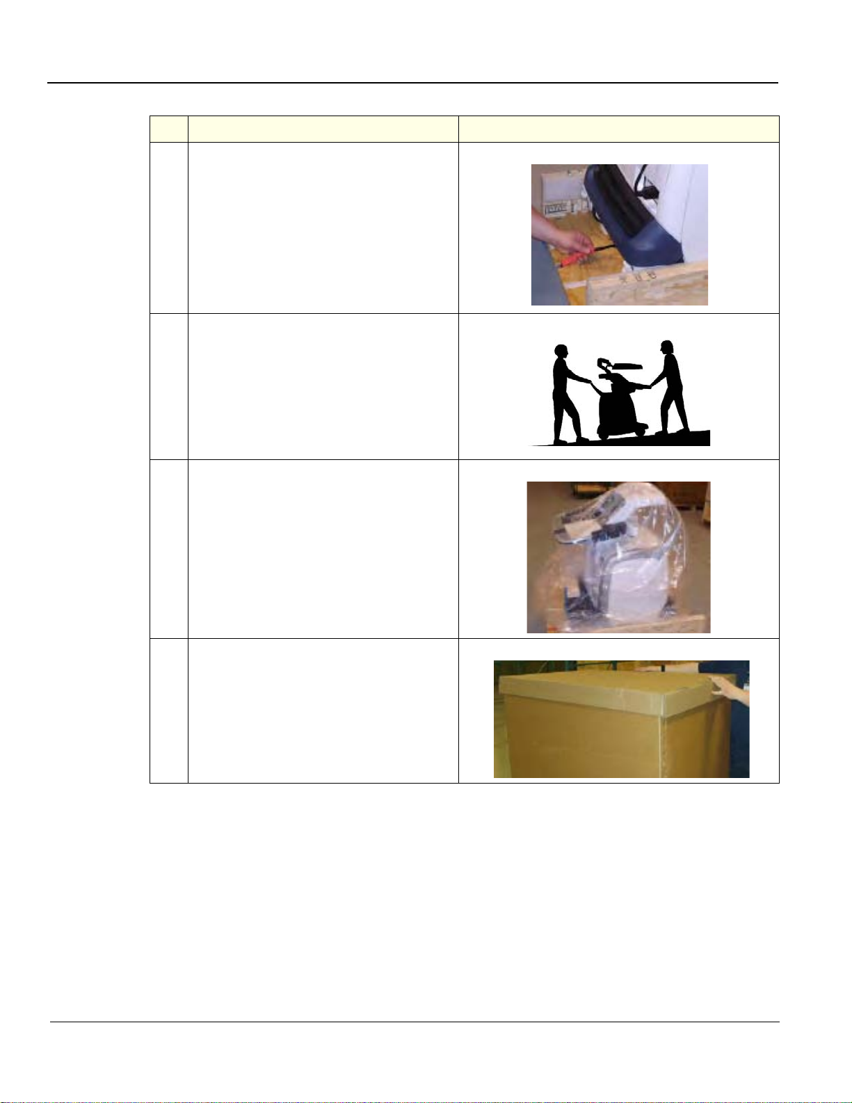
GE HEALTHCARE
DIRECTION 5180263-100, REV 5 LOGIQ E9 Service Manual
Table 3-3 Uncrating Instructions (Continued)
Steps Corresponding Graphic
11.
Disconnect the tie-down strap at the rear of
the LOGIQ E9.
12.
Pull the LOGIQ E9 down the Pallet Base
ramp.
Note: Remember to pull in the LOGIQ E9
from the back for safer transportation.
13.
Remove the clear plastic (wrapped around
the LOGIQ E9) from the unit.
14.
Place all of the filling inside the
Transportation Box. Close the box, and
store the filling for possible future use.
Section 3-4
Packing materials - recycling information
The packing materials for LOGIQ E9 are recyclable:
• The Transportation Box is made of cardboard.
• Lever lockings (hinges) are made of zinc plated steel.
• The inner reinforcements are made of Ethafoam (Polyethylene foam).
• The plastic foil is made of LDPE (Low Density Polyethylene).
3 - 12 Section 3-4 - Packing materials - recycling information
Page 85

GE HEALTHCARE
DIRECTION 5180263-100, REV 5 LOGIQ E9 Service Manual
Section 3-5
Preparing for setup
3-5-1 Verify Customer Order
Compare items received by the customer to that which is listed on the delivery order. Report any item s
that are missing, back ordered, or damaged.
3-5-2 Physical inspection
Verify that the LOGIQ E9 arrived intact (visual inspection).
If the LOGIQ E9 has been damaged, please refer to “Damage in Transportation “on page x in the
beginning of this manual.
3-5-2-1 LOGIQ E9 voltage settings
See: 3-6-3-1 "Verification of the LOGIQ E9’s voltage setting" on page 3-17.
3-5-3 Volume Navigation Stand
To assemble the Volume Navigation Stand, See: 8-15-2 "Assembling or replacing the Roll Stand" on
page 8-550 or 8-15-4 "On-Board V Nav Stand Option Contents, location and placement of parts" on
page 8-559.
Chapter 3 LOGIQ E9 Setup 3 - 13
Page 86
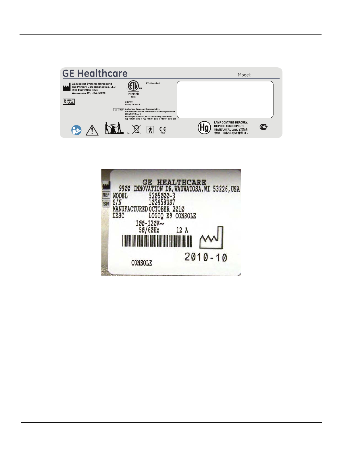
GE HEALTHCARE
DIRECTION 5180263-100, REV 5 LOGIQ E9 Service Manual
3-5-3-1 Back Cover Label and ETL testing laboratories sa fety rating label (ETL may not be present)
Figure 3-4 Back Cover Label with ETL Label
LOGIQ E9
MEDICAL
EQUIPMENT
5197104 revX
135
Figure 3-5 Rating Plate Label - R3.x and earlier 100-120V shown
3 - 14 Section 3-5 - Preparing for setup
Page 87
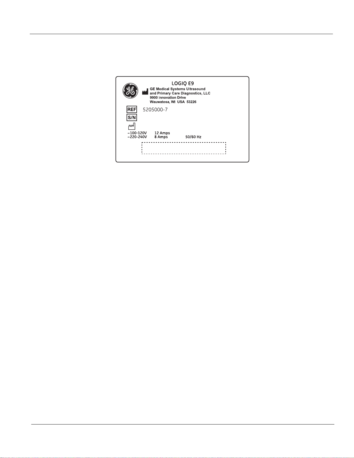
GE HEALTHCARE
DIRECTION 5180263-100, REV 5 LOGIQ E9 Service Manual
3-5-3-1 Back Cover Label and ETL testing laboratories safety rating label (ETL may not be present)
(cont’d)
Figure 3-6 Rating Plate Label - R4.x.x
3-5-4 EMI protection
This unit has been designed to minimize the effects of Electro-Ma gnetic Interference (EMI). Many of the
covers, shields, and screws are provided primarily to protect the LOGIQ E9 from image artifacts caused
by this interference. For this reason, it is imperative that all covers and hardware are installed and
secured before the unit is put into operation.
See: 2-2-4 "EMI limitations" on page 2-5 for more information about EMI protection.
Chapter 3 LOGIQ E9 Setup 3 - 15
Page 88
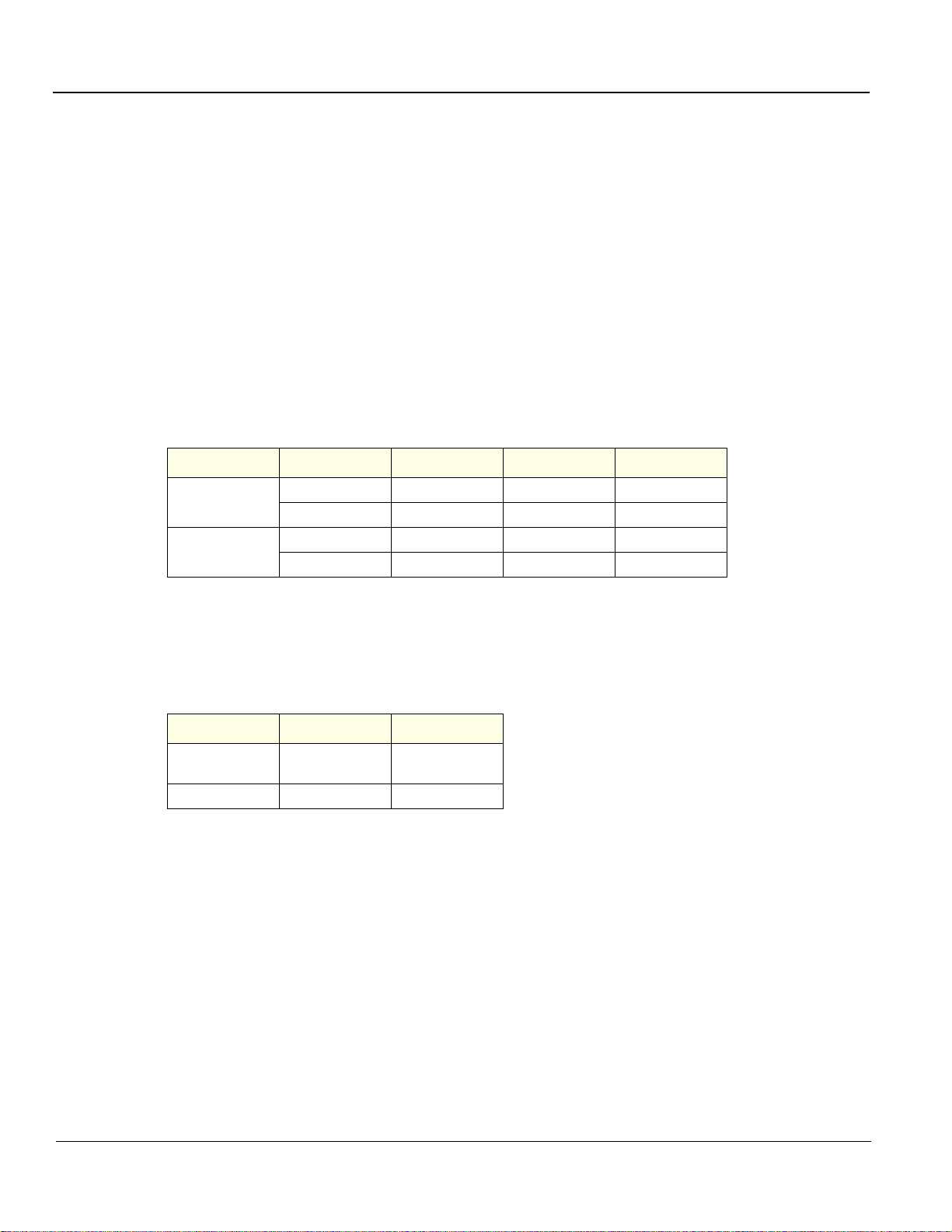
GE HEALTHCARE
DIRECTION 5180263-100, REV 5 LOGIQ E9 Service Manual
Section 3-6
Completing the setup
3-6-1 Purpose of this section
This section describes how to complete the set up of LOGIQ E9.
3-6-2 LOGIQ E9 specifications
3-6-2-1 LOGIQ E9 requirements verification
• Verify that the site meets the requirements listed in (see: Section 2-3 "Facility needs" on p age 2-7).
• Verify that the specifications below don’t conflict with any on-site conditions.
3-6-2-2 Physical dimensions
The physical dimensions of the LOGIQ E9 unit are summarized in Table 3-4.
Table 3-4 Physical dimensions of LOGIQ E9 with monitor and peripherals
PART NUMBER HEIGHT* WIDTH DEPTH UNIT
5205000,
-2, -3, -4, -5, -6
5205000-7
1130 585 830 mm
44.5 23.03 32.67 Inches
1300 585 830 mm
51.2 21.9 32.7 Inches
* Dimensions given with floating keyboard stowed for transport and the LCD Monitor down.
3-6-2-3 Weight with monitor and peripherals
Table 3-5 Weight of LOGIQ E9 with monitor and peripherals
PART NUMBER WEIGHT [KG] WEIGHT [LBS]
5205000,
-2, -3, -4, -5, -6
5205000-7 140 390
135 298
3-6-2-4 Acoustic noise output
Less than 48 dB(A) at 20 degrees Celsius, measured in the operators head position, 20 cm in front of
the keyboard’s right corner, at 1.30 m above the floor, and in a distance of 1 meter at all four sides, 1
meter above the floor.
3 - 16 Section 3-6 - Completing the setup
Page 89

GE HEALTHCARE
WARNINGWARNING
DIRECTION 5180263-100, REV 5 LOGIQ E9 Service Manual
3-6-3 Electrical specifications
CONNECTING A LOGIQ E9 UNIT TO THE WRONG VOLTAGE LEVEL WILL MOST
LIKELY DESTROY THE UNIT.
3-6-3-1 Verification of the LOGIQ E9’s voltage setting
Verify that the mains voltage specified for the unit is available on-site.
The voltage setting for the unit is found on a label on the back of the LOGIQ E9 on lower rear frame of
the LOGIQ E9.
3-6-3-2 Electrical specifications for LOGIQ E9
See: Table 2-3 on page 2-3 for the electrical specifications for LOGIQ E9 include LCD and on board
peripherals.
Chapter 3 LOGIQ E9 Setup 3 - 17
Page 90

GE HEALTHCARE
DIRECTION 5180263-100, REV 5 LOGIQ E9 Service Manual
3-6-4 Connections on the I/O Rear Panel
NOTE: Accessory equipment connected to the analog and digi tal interfaces must be certified according
to the respective IEC standards (e.g. IEC60950 for data processing equipmen t an d IEC606011 for medical equipment). Furthermore, all complete configurations shall comply with the valid
version of the system standard IEC60601-1-1. Everybody who connects additional equipment
to the signal input part or signal output part of LOGIQ E9, configures a medical system, and is
therefore responsible that the system complies with the requirements of the valid version of
IEC60601-1-1. If in doubt, consult the te chnical service department or your local represen tative
for GE Healthcare.
3-6-4-1 Connect Ethernet
Connect the Ethernet cable to the Ethernet connector (3) on the External I/O (rear side of LOGIQ E9).
Figure 3-7 Ethernet, Audio (1) and DVI-I (2) connection for External Monitor on
rear side of LOGIQ E9 - R3.x and earlier
3 - 18 Section 3-6 - Completing the setup
Page 91
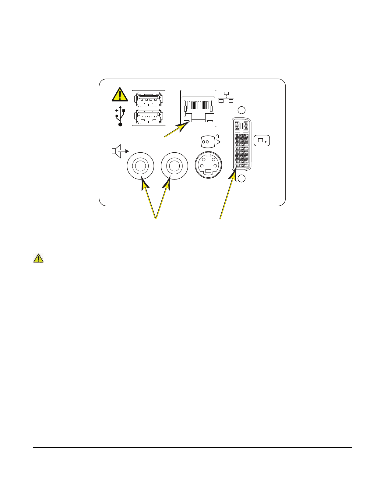
GE HEALTHCARE
CAUTION
DIRECTION 5180263-100, REV 5 LOGIQ E9 Service Manual
3-6-4-1 Connect Ethernet (cont’d)
Figure 3-8 Audio (1), Ethernet (2) and DVI-I (3) connection for External Monitor on
rear side of LOGIQ E9 - R4.x
2
RL
4
3
2
1
To avoid breaking the back cover while opening it in order to connec t up the network cable, use
a flat blade screw driver or plastic card and pull hard to open up the back cover door.
3-6-4-2 Connect USB Flash Drive
Refer to the current revision of the LOGIQ E9 Basic User Manual, Chapter 3, Section 7.
1
3
Chapter 3 LOGIQ E9 Setup 3 - 19
Page 92

GE HEALTHCARE
DIRECTION 5180263-100, REV 5 LOGIQ E9 Service Manual
3-6-5 Connections on the Patient I/O panel
3-6-5-1 Connect ECG
Refer to Chapter 10 in the Basic User Manual for more information.
3-6-6 Connecting Probes
3-6-6-1 Introduction to Connecting Probes
Probes can be connected at any time, whether the unit is on or off.
R3.x and earlier LOGIQ E9s have two types of probe ports: one non-DLP probe port and three DLP
probe ports (Figure 3-10). R4.x LOGIQ E9s have one type of probe ports: four DLP probe ports (Figur e
3-9).
The non-DLP probe port is compatible with the S1-5, S4-10, 6Tc (TEE probe), and 3CRF probe
connectors.
The three DLP probe ports are specific to the LOGIQ E9 probe connectors.
Figure 3-9 Probe connectors - (1) Non-DLP and (2) DLP Probe Port - R3.x and earlier
1
R4.x and later LOGIQ E9s have one type of probe ports: four DLP probe ports (Figure 3-10).
Figure 3-10 Probe connectors, four DLP Probe Ports - R4.x
2
3 - 20 Section 3-6 - Completing the setup
Page 93

GE HEALTHCARE
CAUTION
CAUTION
CAUTION
CAUTION
DIRECTION 5180263-100, REV 5 LOGIQ E9 Service Manual
3-6-6-2 Connect a probe
NOTE: It is not necessary to turn OFF power to connect or disconn e ct a pr ob e.
DO NOT ALLOW THE PROBE HEAD TO HANG FREELY. EXCESSIVE IMPACT TO THE PROBE
WILL RESULT IN IRREPARABLE DAMAGE.
TO PREVENT PROBE CONNECTOR PINS DAMAGE, OR PCB BOARD DAMAGE, DO NOT USE
EXCESSIVE FORCE WHEN CONNECTING THE PROBES.
1.) Before connecting the probe:
a.) Perform a visual check of the probe pins and LOGIQ E9 sockets.
b.) Remove any dust or foam rests from the probe pins.
c.) Verify the probe and the probe cable for any visual damage.
2.) Hold the probe connector vertically with the cable pointing upward.
3.) Turn the connector locking handle counter-clockwise to the horizontal position.
4.) Align the connector with the probe port and carefully push into place.
5.) Turn the locking handle clockwise to the full vertical position to lock in place.
6.) Position the probe cable so that it is not resting on the floor.
KEEP THE PROBE CABLES AWAY FROM THE WHEELS.
DO NOT BEND THE PROBE CABLES.
DO NOT CROSS CABLES BETWEEN PROBES.
3-6-6-3 Disconnect a probe
1.) Rotate the lock handle counter-clockwise to the horizontal position to unlock the connector.
2.) Remove the connector from the port.
3.) Ensure that the probe head is clean before placing the probe in its storage case, see: 10-6-4
"Cleaning" on page 10-11 for cleaning instructions.
REFER TO THE TEE PROBE MANUAL FOR FURTHER INSTRUCTIONS (DIRECTION KZ192871).
Chapter 3 LOGIQ E9 Setup 3 - 21
Page 94

GE HEALTHCARE
DANGER
DANGER
DANGER
CAUTION
NOTICE
DIRECTION 5180263-100, REV 5 LOGIQ E9 Service Manual
3-6-7 Power On/Boot Up
3-6-7-1 Warnings
ALWAYS CONNECT THE UNIT TO A FIXED POWER SOCKET WHICH HAS THE
PROTECTIVE GROUNDING CONNECTOR.
NEVER USE A THREE-TO-TWO PRONG ADAPTER; THIS DEFEATS THE
SAFETY GROUND.
ENSURE THAT THE POWER CORD AND PLUG ARE INTACT AND THAT THE
POWER PLUG IS THE PROPER HOSPITAL-GRADE TYPE (WHERE REQUIRED).
LOGIQ E9 REQUIRES ALL COVERS
OPERATE THIS UNIT ONLY WHEN ALL BOARD COVERS AND FRAME PANELS ARE
SECURELY IN PLACE. THE COVERS ARE REQUIRED FOR SAFE OPERATION, GOOD LOGIQ E9
PERFORMANCE AND COOLING PURPOSES.
Use only power supply cords, cables and plugs provided by or designated by GE Healthcare.
NOTE: Do not cycle the Circuit Breaker ON-OFF-ON in less than five seconds. When turning OFF th e
Circuit Breaker, WAIT until the ON/OFF button is no longer lit. The LOGIQ E9 should deenergize completely before turning the circuit breaker ON.
3-6-7-2 Detailed Procedure
For a detailed procedure, see: 4-2-3 "Power ON/Boot Up" on page 4-3.
3 - 22 Section 3-6 - Completing the setup
Page 95

GE HEALTHCARE
DIRECTION 5180263-100, REV 5 LOGIQ E9 Service Manual
3-6-7-3 Connect AC (mains) Power to the LOGIQ E9
Connecting AC Power to the LOGIQ E9 ultrasound unit involves preliminary checks of the power cord,
voltage level and compliance with electrical safety requirements.
NOTE: The LOGIQ E9 will function on Voltages from 100-240 Volts and 50 or 60 Hz. However, if using
220 volt power, then a center tapped power source is required (North America Only).
1.) Ensure that the wall outlet is of appropriate type, and that the Circuit Breaker is turned off.
2.) Uncoil the power cable, allowing sufficient slack so that the unit can be moved slightly.
3.) Verify that the power cable is without any visible scratches or any sign of damage.
4.) Verify that the on-site mains voltage is within the limits indicated on the rating label ne ar the Circuit
Breaker on the rear of the unit.
5.) Connect the Power Cable’s female plug to the Power Inlet at the rear of the unit.
6.) Lock the plug in position with the Retaining Clamp (ACC Clamp).
7.) Verify that the Mains Power Circuit Breaker is in OFF position, if not, switch it OFF.
Figure 3-11 The Circuit Breaker and ON/OFF button
8.) Connect the Power Cable’s other end (male plug) to a hospital grade mains power outlet with the
proper rated voltage, and the unit is ready for Power ON/Boot Up.
Chapter 3 LOGIQ E9 Setup 3 - 23
Page 96
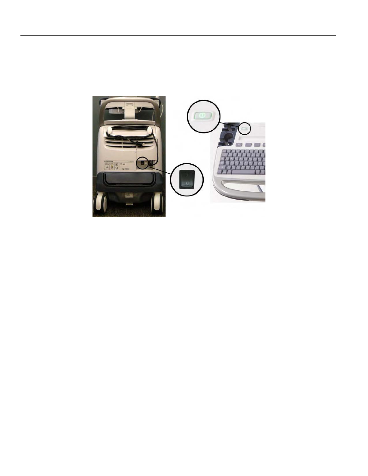
GE HEALTHCARE
DIRECTION 5180263-100, REV 5 LOGIQ E9 Service Manual
3-6-7-4 Switch ON the AC Power to LOGIQ E9
1.) Switch ON the Mains Power Circuit Breaker at the r ear of the unit. The ON/OFF button will become
amber.
Figure 3-12 The Circuit breaker and ON/OFF button
You should hear a “click” from the relays in the AC Power and the unit is ready to boot. The ON/OFF
button will turn amber. This indicates that there is power to the PS, but the system is OFF.
2.) Press once on the ON/OFF button on the Operator Panel to boot the unit. The ON/OFF button will
turn green when it is pressed.
During a normal boot, you may observe that:
a.) The unit’s ventilation fan starts on full speed, but slows down after a few seconds (liste n to the
fan sound).
b.) Power is distributed to the peripherals, Operator Panel (Console), Monitor, Front End
Processor and Back End Processor.
c.) Back End Processor and rest of the LOGIQ E9 starts with the sequence listed in the next steps:
d.) Back End Processor is turned ON and starts to load the software.
e.) The Start Screen is displayed on the monitor.
f.) A start-up bar indicating the time used for software loading, is displayed on the monitor.
g.) The software initiates and sets up the Front End electronics and the rest of the instrument.
h.) The backlight in the keyboard is lit.
i.) As soon as the software has been loaded, either a 2D screen is displayed on the screen,
indicating that a probe has been connected, or a No Mode screen is displayed, indicating that
no probe has been connected.
3 - 24 Section 3-6 - Completing the setup
Page 97

GE HEALTHCARE
DIRECTION 5180263-100, REV 5 LOGIQ E9 Service Manual
3-6-7-4 Switch ON the AC Power to LOGIQ E9 (cont’d)
Figure 3-13 2D Screen on the display
NOTE: Total time used for start-up is typically less than 170 seconds. When using the sleep mode
(R2.x.x or later), start-up time is less then 120 seconds. If starting after a power loss or a lockup, the start-up time may be up to four minutes.
Chapter 3 LOGIQ E9 Setup 3 - 25
Page 98
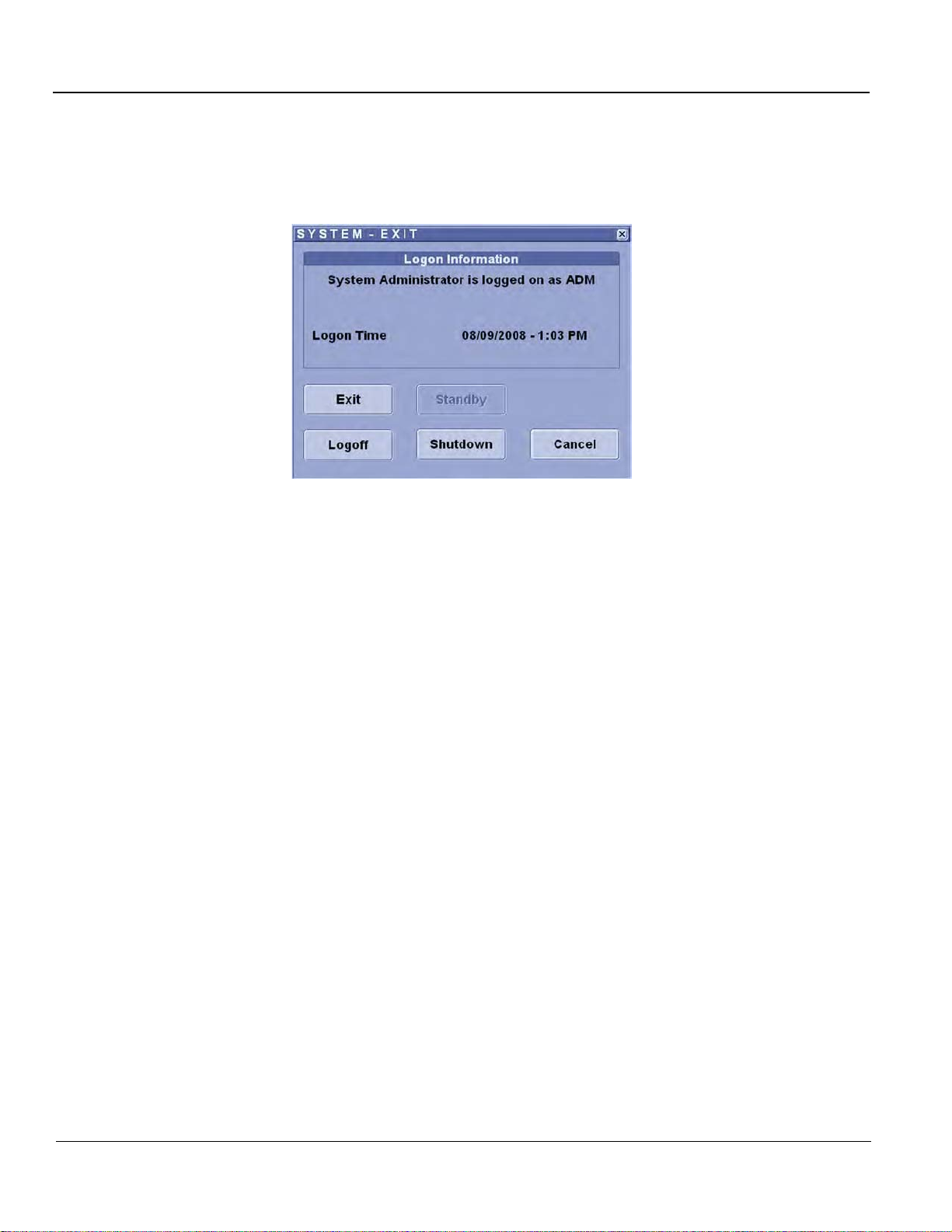
GE HEALTHCARE
DIRECTION 5180263-100, REV 5 LOGIQ E9 Service Manual
3-6-8 Power shut down
When you switch off the unit, the system performs an automatic shutdown sequence.
Figure 3-14 System - Exit menu - R1.x.x
The SYSTEM - EXIT menu, used when switching off the unit, gives you these choices:
• Logoff
Use this button to log off the current user.
The system remains ON and ready for a new user to log on.
If the Logoff button is dimmed, it indicates that no user is logged on to the unit at the moment.
• Shutdown
Use this button to shut down the system. The entire system will shut down. It is recommended to
perform a full shutdown at least once a week.
If the Shutdown button is dimmed, press the ON/OFF button or Alt F10 to shut down the unit.
•Cancel
Use this button to exit from the Syst em-Exit menu and return to the previous operation.
3 - 26 Section 3-6 - Completing the setup
Page 99
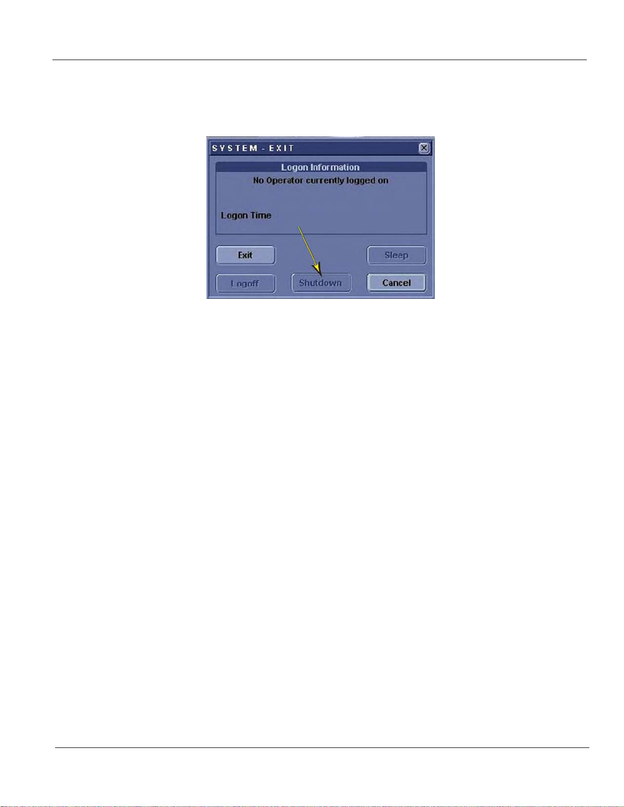
GE HEALTHCARE
DIRECTION 5180263-100, REV 5 LOGIQ E9 Service Manual
3-6-8Power shut down (cont’d)
Sleep mode (only available in LOGIQ E9 running R2.x.x and R3.x.x software).
Figure 3-15 System - Exit menu
The SYSTEM - EXIT menu, used when switching off the unit, gives you these choices:
• Logoff
Use this button to log off the current user.
The system remains ON and ready for a new user to log on.
If the Logoff button is dimmed, it indicates that no user is logged on to the unit at the moment.
• Shutdown
Use this button to shut down the system. The entire system will shut down. It is recommended to
perform a full shutdown at least once a week.
If the Shutdown button is dimmed, press the ON/OFF button or Alt F10 to shut down the unit.
•Cancel
Use this button to exit from the Syst em-Exit menu and return to the previous operation.
Chapter 3 LOGIQ E9 Setup 3 - 27
Page 100
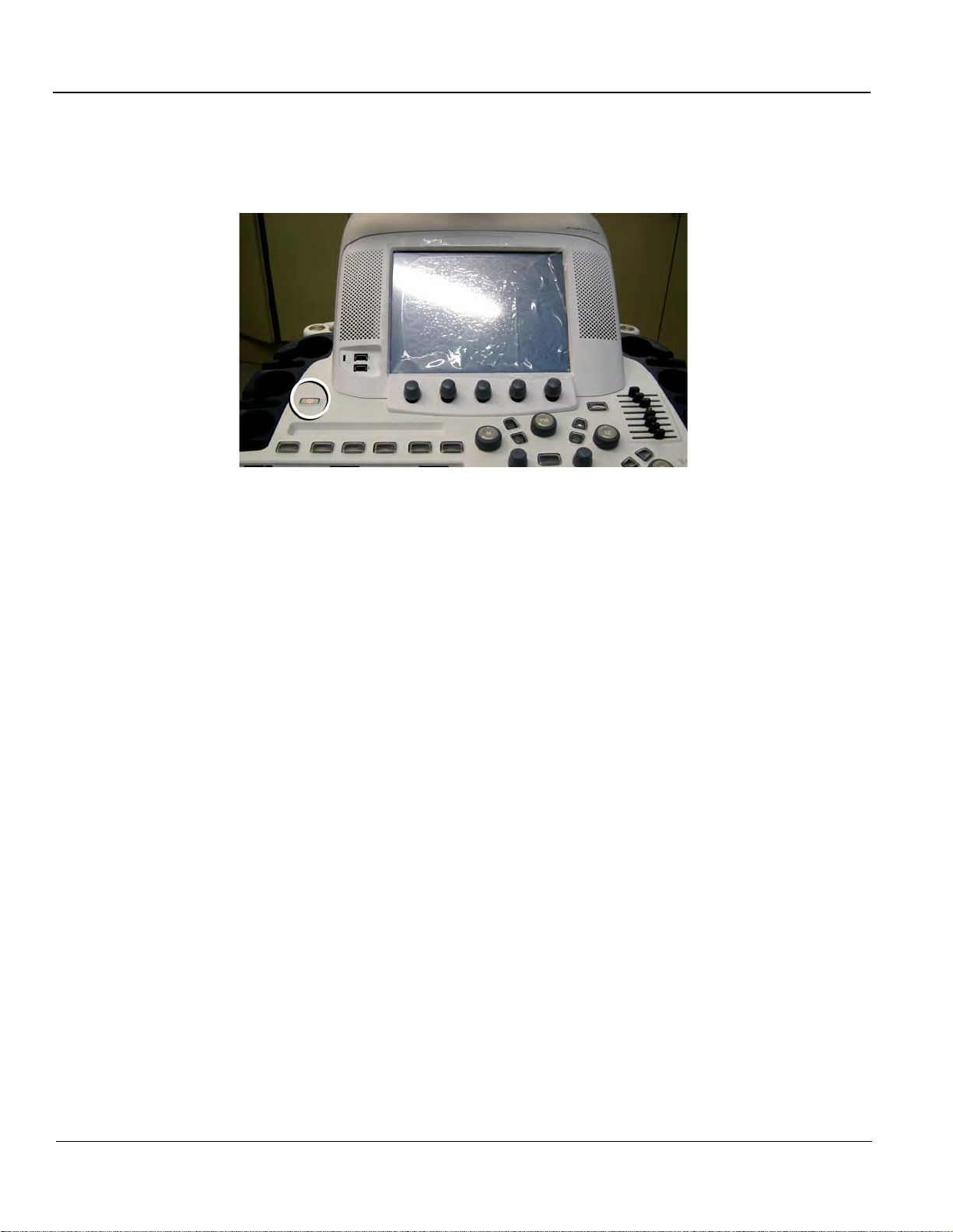
GE HEALTHCARE
DIRECTION 5180263-100, REV 5 LOGIQ E9 Service Manual
3-6-9 Complete power down
1.) Press once on the ON/OFF button on the Operator Panel to display the System - Exit menu.
Figure 3-16 Press once on the ON/OFF button
3 - 28 Section 3-6 - Completing the setup
 Loading...