

Page 1

Technical Publications
0459
Direction 5454884-100 English
Rev. 1
LOGIQ E9 User Guide
Version R4
Operating Documentation
Copyright 2012 By General Electric Co.
Page 2

Regulatory Requirement
0459
LOGIQ E9 complies with regulatory requirements of the following European
Directive 93/42/EEC concerning medical devices.
This manual is a reference for the LOGIQ E9. It applies to Version R4 software for
the LOGIQ E9 ultrasound system.
GE Healthcare
P.O. Box 414, Milwaukee, Wisconsin 53201 U.S.A.
(Asia, Pacific, Latin America, North America)
GE Ultraschall Deutschland GmbH & Co. KG
Beethovenstrasse 239
Postfach 11 05 60
D-42655 Solingen GERMANY
TEL: 49 212.28.02.208; FAX: 49 212.28.02.431
Page 3

Revision History
Reason for Change
DATE
REV
Rev. 1 2012/11/09 Initial Release
(YYYY/MM/DD)
List of Effective Pages
REASON FOR CHANGE
REVISION
PAGE NUMBER
Title Page Rev. 1 Chapter 2 Rev. 1
Revision History Rev. 1 Chapter 3 Rev. 1
Regulatory Requirements Rev. 1 Chapter 4 Rev. 1
Table of Contents Rev. 1 Index Rev. 1
Chapter 1 Rev. 1
NUMBER
PAGE NUMBER
REVISION
NUMBER
Please verify that you are using the latest revision of this document. Information
pertaining to this document is maintained on ePDM (GE Healthcare electronic Product
Data Management). If you need t o kn ow the latest re vision, co nt a ct your d istri butor, local
GE Sales Representative or in the USA call the GE Ultra sound Clinical Answer Center at
1 800 682 5327 or 1 262 524 5698.
LOGIQ E9
–
User Guide
Direction 5454884-100 English Rev. 1
i-1
Page 4

This page intentionally left blank.
i-2
LOGIQ E9
Direction 5454884-100 English
–
User Guide
Rev. 1
Page 5

Regulatory Requirements
Conformance Standards
The following classifications are in accordance with the IEC/
EN 60601-1:6.8.1:
• According to 93/42/EEC Medical Device Directive, this is
Class IIa Medical Device.
• According to IEC/EN 60601-1,
• Equipment is Class I, Type B with BF or CF Applied
Parts.
• According to CISPR 11,
• Equipment is Group 1, Class A ISM Equipment.
This product complies with the regulatory requirement of the
following:
• Council Directive 93/42/EEC concerning med ica l devic es :
the CE label affixed to the product testifies compliance to
the Directive.
The location of the CE marking is shown in the Safety
chapter of this manual.
Authorized EU Representative
European registered place of business:
GE Medical Systems Information Technologies GmbH
(GEMS IT GmbH)
Munzinger Strasse 3, D-79111 Freiburg, GERMANY
Tel: +49 761 45 43 -0; Fax: +49 761 45 43 -233
LOGIQ E9
Direction 5454884-100 English Rev. 1
–
User Guide
i-3
Page 6

Conformance Standards (continued)
• International Electrotechnical Commission (IEC).
• IEC/EN 60601-1 Medical Electrical Eqiupment, Part 1
General Requirements for Safety.
• IEC/EN 60601-1-1 Safety requirements for medical
electrical systems.
• IEC/EN 60601-1-2 Electromagnetic compatibility -
Requirements and tests.
• IEC/EN 60601-1-4 Programmable electrical medical
systems.
• IEC 60601-1-6 (Usability), EN 1041 (Information
supplied with medical devices)
• IEC 60601-2-37 Medical electrical equipment. Particular
requirements for the safety of ultrasonic medica l
diagnostic and monitoring equipment.
• International Organization of Standards (ISO)
• ISO 10993-1 Biological evaluation of medical devices.
• Underwriters’ Laboratories, Inc. (UL), an independent
testing laboratory.
• UL 60601-1 Medical Electrical Equipment, Part 1
General Requirements for Safety.
• Canadian Standards Association (CSA).
• CSA 22.2, 601.1 Medical Electrical Equipment, Part 1
General Requirements for Safety.
• NEMA/AIUM Acoustic Output Display Standard (NEMA
UD-3).
• Medical Device Good Manufacturing Practice Manual
issued by the FDA (Food and Drug Administration,
Department of Health, USA).
i-4
LOGIQ E9
Direction 5454884-100 English
–
User Guide
Rev. 1
Page 7

Certifications
DANGER
• General Electric Medical Systems is ISO 9001 and
ISO 13485 certified.
Original Documentation
• The original document was written in English.
Country Specific Approval
• JAPAN
MHLW Certified Number: 220ABBZX00177000
• KOREA
KFDA License 09-180
• USA AND TERRITORIES
The following optional features ARE NOT available in the
USA and its territories:
– Elastography Quanitfication
– Contrast Enhanced Ultrasound
– Breast Measure Assistant
– OB Measure Assistant
Importer Information
LOGIQ E9
Direction 5454884-100 English Rev. 1
–
User Guide
• Turkey
ITHALATÇI
PENTA ELEKTRONIK MEDIKAL
SISTEMLER SAN. VE TIC. A.S.
HOSDERE CAD. FUAR SOK. 5 / 3
Y. AYRANCI / ANKARA
i-5
Page 8

i-6
LOGIQ E9
Direction 5454884-100 English
–
User Guide
Rev. 1
Page 9

Conformance Standards - - - - - - - - - - - - - - - - - - - - - - - - - - - - - - - - - - - i-3
Certifications - - - - - - - - - - - - - - - - - - - - - - - - - - - - - - - - - - - - - - - - - - - i-5
Original Documentation- - - - - - - - - - - - - - - - - - - - - - - - - - - - - - - - - - - - i-5
Country Specific Approval - - - - - - - - - - - - - - - - - - - - - - - - - - - - - - - - - - i-5
Importer Information - - - - - - - - - - - - - - - - - - - - - - - - - - - - - - - - - - - - - - i-5
Table of Contents
Chapter 1 — Getting Started
Console Overview
Attention - - - - - - - - - - - - - - - - - - - - - - - - - - - - - - - - - - - - - - - - - - - - - 1-2
Prescription Device- - - - - - - - - - - - - - - - - - - - - - - - - - - - - - - - - - - - - - 1-2
Indications for Use - - - - - - - - - - - - - - - - - - - - - - - - - - - - - - - - - - - - - - 1-3
Contraindication - - - - - - - - - - - - - - - - - - - - - - - - - - - - - - - - - - - - - - - - 1-4
Important Notices - - - - - - - - - - - - - - - - - - - - - - - - - - - - - - - - - - - - - - - 1-5
Console Graphics- - - - - - - - - - - - - - - - - - - - - - - - - - - - - - - - - - - - - - - 1-7
Moving the System
Before moving the system- - - - - - - - - - - - - - - - - - - - - - - - - - - - - - - - 1-18
When moving the system - - - - - - - - - - - - - - - - - - - - - - - - - - - - - - - - 1-20
Operator Panel Movement Controls - - - - - - - - - - - - - - - - - - - - - - - - - 1-21
Setting the front wheels lock - - - - - - - - - - - - - - - - - - - - - - - - - - - - - - 1-23
System Start-Up
Power On- - - - - - - - - - - - - - - - - - - - - - - - - - - - - - - - - - - - - - - - - - - - 1-24
Power Off- - - - - - - - - - - - - - - - - - - - - - - - - - - - - - - - - - - - - - - - - - - - 1-25
Circuit breaker - - - - - - - - - - - - - - - - - - - - - - - - - - - - - - - - - - - - - - - - 1-27
Probes
Introduction - - - - - - - - - - - - - - - - - - - - - - - - - - - - - - - - - - - - - - - - - - 1-28
Connecting the Probe - - - - - - - - - - - - - - - - - - - - - - - - - - - - - - - - - - - 1-29
Cable Handling - - - - - - - - - - - - - - - - - - - - - - - - - - - - - - - - - - - - - - - 1-30
Activating the Probe - - - - - - - - - - - - - - - - - - - - - - - - - - - - - - - - - - - - 1-30
Disconnecting the Probe - - - - - - - - - - - - - - - - - - - - - - - - - - - - - - - - - 1-31
Probe Discussion - - - - - - - - - - - - - - - - - - - - - - - - - - - - - - - - - - - - - - 1-31
Biopsy Special Concerns- - - - - - - - - - - - - - - - - - - - - - - - - - - - - - - - - 1-41
Preparing for a Biopsy- - - - - - - - - - - - - - - - - - - - - - - - - - - - - - - - - - - 1-43
Surgery/Intra-operative Use- - - - - - - - - - - - - - - - - - - - - - - - - - - - - - - 1-64
Beginning an Exam
Scanning a New Patient - - - - - - - - - - - - - - - - - - - - - - - - - - - - - - - - - 1-66
Patient Screen - - - - - - - - - - - - - - - - - - - - - - - - - - - - - - - - - - - - - - - - 1-68
Chapter 2 — Performing an Exam
Optimizing the Image
B-Mode Controls- - - - - - - - - - - - - - - - - - - - - - - - - - - - - - - - - - - - - - - - 2-2
Table of Contents
LOGIQ E9
Direction 5454884-100 English Rev. 1
–
User Guide
i-7
Page 10

Color Flow Mode Controls - - - - - - - - - - - - - - - - - - - - - - - - - - - - - - - - - 2-5
M-Mode Controls - - - - - - - - - - - - - - - - - - - - - - - - - - - - - - - - - - - - - - - 2-7
M Color Flow Mode- - - - - - - - - - - - - - - - - - - - - - - - - - - - - - - - - - - - - - 2-7
Doppler Mode Controls - - - - - - - - - - - - - - - - - - - - - - - - - - - - - - - - - - - 2-8
3D Mode - - - - - - - - - - - - - - - - - - - - - - - - - - - - - - - - - - - - - - - - - - - - 2-10
Other Controls - - - - - - - - - - - - - - - - - - - - - - - - - - - - - - - - - - - - - - - - 2-11
Measurement and Analysis
Introduction - - - - - - - - - - - - - - - - - - - - - - - - - - - - - - - - - - - - - - - - - - 2-16
Location of Measurement Controls- - - - - - - - - - - - - - - - - - - - - - - - - - 2-17
B-Mode Measurements- - - - - - - - - - - - - - - - - - - - - - - - - - - - - - - - - - 2-18
Doppler Mode Measurements - - - - - - - - - - - - - - - - - - - - - - - - - - - - - 2-26
M-Mode Measurements- - - - - - - - - - - - - - - - - - - - - - - - - - - - - - - - - - 2-29
Viewing and Editing Worksheets - - - - - - - - - - - - - - - - - - - - - - - - - - - 2-31
Clinical Measurement Accuracy - - - - - - - - - - - - - - - - - - - - - - - - - - - - 2-36
Setting up the Off-Line Paper Printer - - - - - - - - - - - - - - - - - - - - - - - - 2-39
Chapter 3 — After the Exam is Over
Probe Overview
Probe Naming Conventions- - - - - - - - - - - - - - - - - - - - - - - - - - - - - - - - 3-2
Probe handling and infection control- - - - - - - - - - - - - - - - - - - - - - - - - - 3-3
Endocavitary Probe Handling Precautions- - - - - - - - - - - - - - - - - - - - - - 3-4
Probe Cleaning Process - - - - - - - - - - - - - - - - - - - - - - - - - - - - - - - - - - 3-5
Coupling gels - - - - - - - - - - - - - - - - - - - - - - - - - - - - - - - - - - - - - - - - - 3-16
System Presets
Foreign Language Keyboard Setup - - - - - - - - - - - - - - - - - - - - - - - - - 3-18
Data Backup
EZBackup and EZMove- - - - - - - - - - - - - - - - - - - - - - - - - - - - - - - - - - 3-25
Backup procedure: user-defined configurations - - - - - - - - - - - - - - - - - 3-32
Restore procedure: patient data- - - - - - - - - - - - - - - - - - - - - - - - - - - - 3-33
Restore procedure: user-defined configurations- - - - - - - - - - - - - - - - - 3-34
Configuring Connectivity
Overview - - - - - - - - - - - - - - - - - - - - - - - - - - - - - - - - - - - - - - - - - - - - 3-35
Connectivity Functions - - - - - - - - - - - - - - - - - - - - - - - - - - - - - - - - - - 3-36
Anti-Virus Software Note- - - - - - - - - - - - - - - - - - - - - - - - - - - - - - - - - 3-37
Electronic Documentation
Accessing Documentation Via a Windows PC- - - - - - - - - - - - - - - - - - 3-39
Accessing Documentation on the Ultrasound Scanner Via the media- - 3-40
Using Online Help Via F1 - - - - - - - - - - - - - - - - - - - - - - - - - - - - - - - - 3-41
Contact Information
Contacting GE Healthcare Ultrasound - - - - - - - - - - - - - - - - - - - - - - - 3-42
Manufacturer - - - - - - - - - - - - - - - - - - - - - - - - - - - - - - - - - - - - - - - - - 3-48
System Data
Features/Specifications- - - - - - - - - - - - - - - - - - - - - - - - - - - - - - - - - - 3-49
System Care and Maintenance
Expected Service Life Description - - - - - - - - - - - - - - - - - - - - - - - - - - 3-55
Inspecting the System- - - - - - - - - - - - - - - - - - - - - - - - - - - - - - - - - - - 3-56
Cleaning the system - - - - - - - - - - - - - - - - - - - - - - - - - - - - - - - - - - - - 3-58
Other Maintenance - - - - - - - - - - - - - - - - - - - - - - - - - - - - - - - - - - - - - 3-63
i-8
LOGIQ E9
Direction 5454884-100 English
–
User Guide
Rev. 1
Page 11

Assistance
Supplies/Accessories - - - - - - - - - - - - - - - - - - - - - - - - - - - - - - - - - - - 3-66
Chapter 4 — Safety
Owner Responsibility
Owner requirements - - - - - - - - - - - - - - - - - - - - - - - - - - - - - - - - - - - - - 4-2
Notice against user modification- - - - - - - - - - - - - - - - - - - - - - - - - - - - - 4-3
Safety Precautions
Precaution Levels- - - - - - - - - - - - - - - - - - - - - - - - - - - - - - - - - - - - - - - 4-4
Hazard Symbols- - - - - - - - - - - - - - - - - - - - - - - - - - - - - - - - - - - - - - - - 4-5
Patient Safety- - - - - - - - - - - - - - - - - - - - - - - - - - - - - - - - - - - - - - - - - - 4-7
Equipment and Personnel Safety- - - - - - - - - - - - - - - - - - - - - - - - - - - 4-11
Classifications - - - - - - - - - - - - - - - - - - - - - - - - - - - - - - - - - - - - - - - - 4-18
EMC (Electromagnetic Compatibility) - - - - - - - - - - - - - - - - - - - - - - - - 4-19
Patient Environmental Devices- - - - - - - - - - - - - - - - - - - - - - - - - - - - - 4-31
Acoustic Output - - - - - - - - - - - - - - - - - - - - - - - - - - - - - - - - - - - - - - - 4-33
Device Labels
Label Icon Description- - - - - - - - - - - - - - - - - - - - - - - - - - - - - - - - - - - 4-37
Warning Label Locations- - - - - - - - - - - - - - - - - - - - - - - - - - - - - - - - - 4-43
Index
LOGIQ E9
Direction 5454884-100 English Rev. 1
–
User Guide
i-9
Page 12

i-10
LOGIQ E9
Direction 5454884-100 English
–
User Guide
Rev. 1
Page 13

Chapter 1
Getting Started
Console Overview, Moving the System, System
Start-up, Probes and Beginning an Exam
LOGIQ E9
Direction 5454884-100 English Rev. 1
–
User Guide
1-1
Page 14

Getting Started
Attention
Console Overview
This manual contains necessary and sufficient information to
operate the system safely. Advanced equipment training may be
provided by a factory trained Applications Specialist for the
agreed-upon time period.
Read and understand all instructions in this manual before
attempting to use the LOGIQ E9 system.
Keep this manual with the equipment at all times. Period ica lly
review the procedures for operation and safety precautions.
Disregarding information on safety is considered abnormal use.
Not all features or products described in this document may be
available or cleared for sale in all markets. Please contact your
local GE Healthcare Ultrasound representative to get th e late st
information.
NOTE: Please note that orders are based on the individually agreed
NOTE: All references to standards / regulations and their revisions are
Prescription Device
upon specifications and may not cont ain all features listed in t his
manual.
valid at the time of publication of the user manual.
CAUTION: United States law restricts this device to sale or use
by, or on the order of a physician.
1-2
LOGIQ E9
Direction 5454884-100 English
–
User Guide
Rev. 1
Page 15

Indications for Use
CAUTION
Frequency of Use
Operator Profile
Clinical Applications
Console Overview
The LOGIQ E9 is intended for use by a qualified physician for
ultrasound evaluation.
Daily (Typically 8 hours)
• Qualified and trained physicians or sonographers with at
least basic ultrasound knowledge.
• The operator must have read and understood the user
manual.
Specific clinical applications and exam types include:
• Fetal/Obstetrics
• Abdominal (includes renal, GYN/Pelvic)
• Pediatric
• Small Organ (breast, testes, thyroid)
• Neonatal Cephalic
• Adult Cephalic
• Cardiac (adult and pediatric)
• Peripheral Vascular
• Musculo-skeletal Conventional and Superficial
• Urology (including prostate)
• Transrectal
• Transvaginal
• Transesophageal
• Intraoperative (abdominal, thoracic, vascular and
neurosurgical)
LOGIQ E9
Direction 5454884-100 English Rev. 1
–
User Guide
This machine should be used in compliance with law. Some
jurisdictions restrict certain uses, such as gender
determination.
1-3
Page 16

Getting Started
Contraindication
The LOGIQ E9 ultrasound system is not intended for ophthalmic
use or any use causing the acoustic beam to pa ss through the
eye.
Only qualified physicians or sonographers should perform
ultrasound scanning on human subjects for medical diagnostic
reasons. Request training, if needed.
1-4
LOGIQ E9
Direction 5454884-100 English
–
User Guide
Rev. 1
Page 17

Console Overview
Important Notices
Do not attempt to install the system alone. General Electric,
Affiliate, or Distributor Field Engineers and Application
Specialists will install and setup the system. See ‘Contact
Information’ on page 3-42 for more information.
NOTICE This medical equipment is approved, in terms of the prevention
of radio wave interference, to be used in hospitals, clinics and
other institutions which are environmentally qualified. The use of
this equipment in an inappropriate environment may cause
some electronic interference to radios and te lev ision s ar ou n d
the equipment.
Ensure that the following is provided for the new system:
• A separate power outlet with a 20 amp circuit breaker for
120 VAC for 120V area, 7.5 amp circuit breaker for
220-240V AC for 220/240V ar ea or 15 amp circuit breaker for
100 VAC for Japan.
• Take precautions to ensure that the console is protected
from electromagnetic interference.
Precautions include:
• Operate the console at least 5 meters (15 feet ) away
from motors, typewriters, elevators, and other sources
of strong electromagnetic radiation (non-medical grade
UPS must be at least 2 meters (6 feet) away from
console).
• Operation in an enclosed area (wood, plaster or
concrete walls, floors and ceilings) helps prevent
electromagnetic interference.
• Special shielding may be required if the console is to be
operated in the vicinity of radio broadcast equipment.
LOGIQ E9
Direction 5454884-100 English Rev. 1
–
User Guide
1-5
Page 18

Getting Started
WARNING
CAUTION
CAUTION
Important Notices (continued)
To avoid risk of fire, the syst em po we r must be sup plie d fr om a
separate, properly rated outlet.
Under no circumstances should the AC power plug be altered,
changed, or adapted to a configuration rated less than
specified. Never use an extension cord or adapter plug.
To help assure grounding reliability, connect to a “hospital
grade” or “hospital only” grounded power outlet.
Use caution to ensure that the power cable does not
disconnect during system use.
If the system is accidentally unplugged, data may be lost.
To avoid leakage current above safety limits as prescribed by
IEC 60601-1 and to ensure continuity of protective earth. DO
NOT connect LOGIQ E9 and mains-operated accessories to a
single or multiple socket extension cord or power strip.
1-6
Figure 1-1. Example Plug and Outlet Configurations
1. 100-120 VAC, 1200 VA
Plug and Outlet Configuration
2. 220-240 VAC, 1200 VA
Plug and Outlet Configuration
LOGIQ E9
Direction 5454884-100 English
–
User Guide
Rev. 1
Page 19

Console Graphics
CAUTION
Console Overview
The following are illustrations of the console:
Figure 1-2. LOGIQ E9 System (right and left side views)
1. LCD
2. Gel Holder / Specialty Probe Holder
3. Operator Panel, Probe Holders with Cable
Management
4. Brake Release / Up/Down Controls
For compatiblity reasons, use only GE approved probes,
peripherals or accessories.
DO NOT connect any probes or accessories without approval
by GE.
5. Peripherals (Black/White Printer, CD/DVD
Drive), V Nav option, and Network Activity/
Speed (Green=1 Gigabyte and Yellow=100 Mb)
and Hard Disk Drive Indicator
6. Probe Connectors
7. Brakes
LOGIQ E9
Direction 5454884-100 English Rev. 1
–
User Guide
1-7
Page 20

Getting Started
WARNING
Console Graphics (continued)
Figure 1-3. LOGIQ E9 System (front and back views)
1. Power On/Off; Operator Panel USB Ports
2. Brake and Up/Down Controls
3. Probe Cable Management Hooks (underneath
Operator Panel)
4. Black/White Printer
5. CD/DVD Drive
6. Network and Hard Disk Drive Indicators. USB
Ports
7. Patient I/O (ECG, CW Probe Connector)
8. Volume Navigation Connectors
DO NOT touch the patient and any of the connectors on the
ultrasound unit simultaneously, including ultrasound probe
connectors.
DO NOT touch the conducting parts of the USB, Ethernet,
Video, Audio cables when connecting equipment to the unit.
9. Probe Connectors
10. Brake Pedal
11. Rear Handle
12. Power Cord Hook
13. Op Panel Up/Down Manual Release Lever
14. Access to Peripheral USB Ports, Audio In/Out,
DVI Connector, Ethernet Connectors, S-Video
15. Breaker, Ground and Power Cord
16. Back Filter
1-8
LOGIQ E9
–
User Guide
Direction 5454884-100 English
Rev. 1
Page 21

USB Ports
CAUTION
CAUTION
CAUTION
Operator Panel
Console Overview
Peripheral devices that use their own AC power source canno t
be attached to the system.
The two Operator Panel USB Ports SHOULD ONLY BE USED
for Bus-powered USB Hard Disk Drives and USB Flash Drives.
The following configurations can be used:
• One or two USB Flash Drives
• One Flash Drive and One Bus-powered Hard Disk Drive
• One Bus-powered Hard Disk Drive
DO NOT plug in TWO Bus-powered Hard Disk Drives at the
same time.
Below Operator Panel and Rear of System
The two USB ports at the back of the system and the two USB
ports below the Operator Panel SHOULD ONLY BE USED for
the following devices:
• Color or Report Printer
NOTE: When connecting an external printer to the LOGIQ E9 via
the USB port on the back of the system, you MUST ensure
that the power supplied to the printer is fed from the same
power feed as the LOGIQ E9. This assures compliance to
leakage currents.
• Flash Drive
• Service Key
ONLY plug in devices to the USB ports located at the rear of
the system WHILE the LOGIQ E9 is NOT powered up . If you
plug in a device while the LOGIQ E9 is powered on, your
system may become unusable.
LOGIQ E9
Direction 5454884-100 English Rev. 1
–
User Guide
1-9
Page 22

Getting Started
CAUTION
CAUTION
CAUTION
Peripheral/Accessory Connector Panel
LOGIQ E9 peripherals CAN ONLY BE properly connected using
the Peripheral/Accessory Connector Panel located behind the
rear door: Color Digital or Report printer, Audio In/Out, DVI
Analog Video Output, S-Video, and Ethernet.
For compatiblity reasons, use only GE-approved prob es,
peripherals, or accessories.
DO NOT connect any probes or accessories without approval
by GE.
The connection of equipment or transmission networks other
than as specified in these instructions can result in electric
shock hazard. Alternate connections will require verification of
compatibility and conformity to IEC/EN 60601-1-1 by the
installer.
To avoid breaking the back cover while opening it in order to
connect up the network cable, use a paper clip an d pull hard to
open up the back cover door.
1-10
LOGIQ E9
Direction 5454884-100 English
–
User Guide
Rev. 1
Page 23

Peripheral/Accessory Connector Panel (continued)
Figure 1-4. Peripheral/Accessory Connector Panel
Table 1-1: Peripheral/Accessory Connector Panel Descriptions
Console Overview
No. Item Type of connector
USB Ports USB 2.0
Ethernet RJ-45 Modular, 8-pin
LOGIQ E9
Direction 5454884-100 English Rev. 1
–
User Guide
1-11
Page 24

Getting Started
Table 1-1: Peripheral/Accessory Connector Panel Descriptions (Continued)
No. Item Type of connector
DVI Port Connector DVI Analog Video Output.
Audio In/Out ACR
S-Video S-Video
Note: Use a DVI to VGA Adapter in order to
connect an analog monitor.
1-12
LOGIQ E9
–
User Guide
Direction 5454884-100 English
Rev. 1
Page 25

Control Panel Map
Console Overview
Figure 1-5. Control Panel
1. Probe and Cord Holder
2. USB Ports (2)
3. Touch Panel and Joystick controls
4. Keyboard
5. Feature Keys
6. Mode/Gain/XYZ (3D) Controls
7. TGC
8. Trackball, Trackball Keys, Pointer, Measure, Comment,
Body Pattern, Clear, Zoom, 3D/4D, P1
9. L/R, Start/Stop, Freeze
10. Steer/Width/Depth/Reverse
11. Auto
12. P2, P3, P4
LOGIQ E9
Direction 5454884-100 English Rev. 1
–
User Guide
1-13
Page 26

Getting Started
Touch Panel
Figure 1-6. Exam Function Controls
1. Patient: Enters Patient screen
2. Scan: Enters scanning mode screen
3. Reports: Activates default report and Touch
Panel of report choices.
4. End Exam: Activates Image Management and
Touch Panel with end of exam options.
NOTE: Different menus are displayed depending on which Touch Panel
is selected.
At the bottom of the Touch Panel, there are five combination
rotary dials/push buttons. The functiona lity of these rotaries
changes, depending upon the currently-displayed menu. Press
the button to switch between controls, or rot ate the dial to adjust
the value, or move the control left/right or up/down to adjust the
value.
5. Utility: Activates system configuration menus.
6. Model: Selects the application to use.
7. Probe Indicator: Indicates and selects the
probes.
1-14
LOGIQ E9
–
User Guide
Direction 5454884-100 English
Rev. 1
Page 27

Monitor Display
Console Overview
Figure 1-7. Monitor Display Tour
Figure 1-8. Monitor Display Tour 2
NOTE: The date on the monitor may truncate the century when using
the YYYY-MM-DD date format.
LOGIQ E9
Direction 5454884-100 English Rev. 1
–
User Guide
1-15
Page 28

Getting Started
Monitor Display (continued)
1. Institution/Hospital Name, Date, Time, Operator
Identification.
2. Patient Name, Patient Identification, Alternate
(Second) Patient Name/Patient Identification.
3. Power Output Readout
4. GE Symbol: Probe Orientation Marker.
5. Worksheet/Direct Report.
6. Gray/Color Bar.
7. Measurement Summary Window.
8. Image.
9. Measurement Calipers.
10. Measurement Results Window.
11. Scan Assistant Icons
12. Image Preview.
13. Image Clipboard.
14. Probe Identifier. Exam Preset.
15. Imaging Parameters by Mode, SoS indicator (if
applicable).
16. Focal Zone Indicator.
17. TGC.
18. Depth Scale.
19. Body Pattern.
20. Cine Gauge.
21. Current date and time, Caps Lock: (lit when on),
network connection indicator (PC=connected,
PC with X=not connected), wireless LAN
indicator (WLAN=connected, WLAN with X=not
connected), DVR status, InSite ExC status,
InSite ExC controls, system messages display.
22. Image Management Icons:
a. Compare Assistant
b. Active Images screen
c. Delete Images screen
d. Next/Previous Image(s); and Clipboard Slide
Show if you press and hold down the [Ctrl]
key + Next or Previous Arrow
e. Save As Menu
f. Number of Images in Exam
g. Thumbnail Size
23. Trackball Key Functionality Status.
24. 6Tc Probe temperature display
25. 6Tc Probe angle display
1-16
LOGIQ E9
–
User Guide
Direction 5454884-100 English
Rev. 1
Page 29

Brightness
Console Overview
Adjusting the monitor's brightness is one of the most important
factors for proper image quality. If these controls are set
incorrectly, the Gain, TGC, Dynamic Range and even Power
Output may have to be changed more often than necessary to
compensate.
The proper setup displays a complete gray scale. The lowest
level of black should just disappear into the backgr ound and the
highest white should be bright, but not saturated.
To adjust the brightness:
1. Press the right adjustment button to increase brightness.
2. Press the left adjustment button to decre ase brightness.
The amount of brightness is shown on a slide bar on the
screen.
Figure 1-9. Brightness adjustment button
1. Adjustment (+) Button
2. Adjust (-) Button
Record any changes to the final brightness settings and leave
this information with the system. Generally speaking, do not
change the controls once they have been set. Once set, the
display then becomes the reference for the hard copy device(s).
Table 1-2: Brightness Settings (Recommended)
Room Condition Brightness
Dark Room (Factory default) 60
Bright Room 100
NOTE: After readjusting the monitor's Brightness, readjust all preset
and peripheral settings.
LOGIQ E9
–
User Guide
Direction 5454884-100 English Rev. 1
1-17
Page 30

Getting Started
Before moving the system
1. Press the Power On/Off switch to power off the system.
See ‘Power Off’ on page 1-25 for more information.
2. Unplug the power cord.
3. All cables from off-board peripheral devices (external Color
Digital/Report printer, etc.) and the ethernet connection
must be disconnected from the console.
4. Ensure that no loose items are left on the console.
5. Wind the power cable around the cable hook below the rear
handle.
NOTE: To prevent damage to the Power Cord, DO NOT pull
excessively on the cord or make sharp bends while
wrapping.
Moving the System
6. Connect all probes to be used while off site. Ensure that
probe cables are out of the way from the wheels and not
protruding beyond the console. Use the probe manageme nt
hooks located below the Operator Panel to further secure
the probe cables.
NOTE: If more than four (4) probes are intended to be used, store
the additional probes securely.
7. Store all other probes in their original cases or in soft cloth
or foam to prevent damage.
1-18
LOGIQ E9
Direction 5454884-100 English
–
User Guide
Rev. 1
Page 31

Before moving the system (continued)
CAUTION
CAUTION
8. Store sufficient gel and other essential accessories in the
provided space.
DO NOT place probes into the front pocket storage area
when moving the system. This is not a storage space for
probes.
9. Adjust the LCD monitor and control panel to their lowest
positions by using the up/down switch on the front of the
operator panel. Make sure the operator panel is locked in
place.
To prevent system damage while not in use AND/OR
before moving the system, flip down the monitor and lock
the monitor arm and operator panel firmly in place.
10. Unlock the wheels.
Moving the System
LOGIQ E9
Direction 5454884-100 English Rev. 1
–
User Guide
1-19
Page 32

Getting Started
CAUTION
CAUTION
When moving the system
1. Always use the front handle grips to move the system.
2. Take e xtra care when moving the system long d istances and
on inclines. Ask for help if necessary.
Avoid ramps that are steeper than ten degrees to avoid
tipping over the
personnel when moving on a steep incline (>5 degrees) or
loading the system into a vehicle for transport.
NOTE: Wheel chair ramps are usually less than five degrees.
DO NOT attempt to move the console using any cables or
fixtures, such as the probe connectors.
3. Use the foot brake (pedal), located on the bottom of the
system in the front, when necessary.
4. Do not let the system strike walls or door frames.
5. Use extra care when crossing door or elevator thresholds.
6. Once the destination is reached, lock the wheels.
system. Utilize additional care and
The system weighs approximately 140kg (309lbs). To avoid
possible injury and equipment damage:
• Be sure the pathway is clear.
• Limit movement to a slow careful walk.
• Use two or more persons to move the system on inclines or
long distances.
1-20
LOGIQ E9
Direction 5454884-100 English
–
User Guide
Rev. 1
Page 33

Operator Panel Movement Controls
CAUTION
The system Operator Panel can be freely moved in all
directions. The vertical displacement of the Operator Panel is
motor driven. The control buttons are located adjacent to the
handles.
Figure 1-10. Operator Panel Movement Controls
To move the Operator Panel sideways, press and hold down the
left button to release and move the Operator Panel sideways
until it is in the desired position.
To park the Operator Panel, after moving Operator Panel
sideways to the desired position, release the left button. After
releasing the left button, the system will lock into position after 3
seconds.
Moving the System
To raise/lower the Operator Panel, press and hold down the Up/
Down toggle button (right button) according ly to raise or lower
the Operator Panel. Release the Up/Down button when the Top
Console is in the desired height.
To manually adjust the Operator Panel, manipulate the metal
lever located in-between the slots on the rear of the LOGIQ E9.
When power is on, the brakes are applied to the Operator
Panel. To move the Operator Panel, release it by using the
Operator Panel Movement Controls. This helps to ensure the
life of the brakes.
LOGIQ E9
Direction 5454884-100 English Rev. 1
–
User Guide
1-21
Page 34

Getting Started
CAUTION
Shutdown
NOTE: Once you select Shutdown, both Operator Panel controls are
Park Lock Reset
Make sure to dock the Operator Panel prior to powering down
the system. You cannot lock the Operator Panel into place
during shutdown or after the system has been shut down.
If you shutdown the system wiithout parking the Operato r Panel,
the message “The operator keyboard is not in parked position.”
appears. Place the Operator Panel in the parked position.
disabled. The brakes are released; XY movement is free but you
cannot move the Operator Panel in the Z plane.
When power is off, the Operator Panel is loose, no breaks are
applied. If you do not dock the operator panel, it will move
freely. Please dock the Operator Panel if you will be moving or
transporting the system.
The Park Lock Reset control releases (undocks) the Operator
Panel and resets the position of the Park Lock.
Park Lock Reset is located on the Utility--> System-->
Peripherals screen under “Miscellaneous.”
Figure 1-11. Park Lock Reset
After you press the Park Lock Reset control, you can hear the
motor moving, releasing the Operator Panel for you to position
as you need.
1-22
LOGIQ E9
Direction 5454884-100 English
–
User Guide
Rev. 1
Page 35

Setting the front wheels lock
CAUTION
The pedal is located between the front wheels of the unit and
enables the user to control the movement of the wheels.
Figure 1-12. Front Pedal Lock/Brake
Table 1-3: Front Pedal Functions
Pedal position Function
Moving the System
1. Left—Swivel Lock Swivel Lock. To move the system, press the Swivel Lock to set
the wheels in a forward-to-back position. First move the system
in the direction you will be going, then press the Swivel Lock. To
release the Swivel Lock, press the center brake release (3).
2. Right—Parking Brake Park. To set the brake, press the right pedal. To release the
brake, press the center brake release.
3. Center—Brake Release Press the center brake to release the swivel lock/parking brake
(3).
When two or more people are releasing the swivel/pivot wheel
controls with the front and rear pe dals, take extra precaution to
prevent unexpected movement which could result in possible
toe injuries.
LOGIQ E9
Direction 5454884-100 English Rev. 1
–
User Guide
1-23
Page 36

Getting Started
CAUTION
Power On
Login
System Start-Up
Press the Power On/Off switch to turn the power on. The
circuit breaker must also be in the on position. For circuit
breaker location, see ‘Circuit breaker’ on page 1-27 for more
information.
Personal IDs and associated passwords can be preset on the
LOGIQ E9.
If the User Auto Logon preset is blank, you are prompted to
login.
1-24
Figure 1-13. Operator Login Window
1. Operator: Select the Operator.
2. Password: Enter Operator’s password (optional).
3. Select type of Logon or Cancel.
• Emergency: Data stored only for the duration of the
current examination.
• OK: Standard logon
• Cancel: Cancel logon
LOGIQ E9
Direction 5454884-100 English
–
User Guide
Rev. 1
Page 37

Power Off
HINTS
CAUTION
System Start-Up
To power off the system:
1. Set the brake and use the operator panel movement
controls to lock the control panel in place.
If the Park Lock does not engage when you attempt to
dock the Operator Panel in place, reset the Park Brake by
selecting “Park Brake Reset” in the Miscellaneous section
on the Utility -> System -> Peripherals page.
2. When you shutdown the system, enter the scan screen and
lightly press the Power On/Off switch at the front of the
system once. The System-Exit window is displayed.
NOTE: DO NOT press and hold down the Power On/Off switch to
shutdown the system. Instead, lightly press the Power On/
Off switch and select Shutdown.
3. Using the Trackball, select Shutdown.
The shutdown process may take up to two (2) minutes and
is completed when the control panel illumination shuts
down.
NOTE: If the system appears non-responsive, press the Power On/
Off switch. After about six (6) seconds, the “Application not
responding” system dialog appears. Select to end all
system processes and shut down the system.
NOTE: When the Extended Power Supply (EPS) is installed, battery
Additional System Information
LOGIQ E9
Direction 5454884-100 English Rev. 1
–
User Guide
4. Disconnect the probes.
Clean or disinfect all probes as necessary. Store them in
their shipping cases or another appropriate probe storage
system to avoid damage.
DO NOT turn off the circuit breaker before the Power On/Off
switch LED is off.
Data may be lost or system software damaged if the circuit
breaker is turned off before the Power On LED is off.
replacement may be necessary if the circuit breaker is turned off
for long periods of time (3 to 6 months).
For optimum system operation, we recommend that you restart
the system at least once every 24-hour period. If you shut down
the system at the end of the day, no other action is needed.
1-25
Page 38

Getting Started
Crash Recovery Instructions
In case of a system crash, power cycle the system. Upon
boot-up, all images and measurements, except for generic
worksheets, are preserved in the system. When the system
returns, the system alerts you that unsaved images are still in
the system from the previous patient. Respond to the prompt to
continue the current patient. Check that all images and
measurements have been preserved in the system. Then
resume the exam.
If the system fails to respond to your commands within a typical
period of time, you need to manually reset the system. Simply
hold down the power switch to initiate a normal power down
sequence. After the system has completely shut down (power
switch amber), restart the system using the standard power-up
sequence. All images and measurements, except fo r generic
worksheets, are preserved in the system. When th e system h as
fully powered up, the system alert s you that unsaved images ar e
still in the system from the previous patient. Respond to the
prompt to continue the current patient. Check that all imag es
and measurements have been preserved in the system. If you
do not have any images on the clipboard, the patient must be
retrieved from the database. Then resum e th e ex am .
Unexpected Power Loss
In case of unexpected power loss,
1. Check the system On/Off LED color (green is on, ambe r is
2. If the LCD monitor shuts down along with the system, then
3. Wait about 2 minutes after such an incident and then turn
4. Wait approximately one minute. The system On/Off switch
5. Turn on the LOGIQ E9 by either turning on the circuit
6. Turn on the scanner by pressing the system On/Off switch.
NOTE: The LOGIQ E9 should be plugged into the regular powe r
off).
the system has detected a power failure. It will then activate
the extended power supply (EPS). The EPS permits us to
maintain the integrity of the scanner dat abase. The system
On/Off switch will be green in this situation.
the circuit breaker off (rear panel of the LOGIQ E9) or
unplug the scanner.
should be dark.
breaker or plugging in the scanner.
outlet and not the emergency power outlet.
1-26
LOGIQ E9
Direction 5454884-100 English
–
User Guide
Rev. 1
Page 39

Circuit breaker
NOTE: If the Circuit Breaker switch does not remain in the On position
System Start-Up
The Circuit Breaker is located at the rear panel of the system.
On supplies main power to all internal systems. Off removes
main power from all internal systems. The circuit breaker
automatically shuts off power to the system in case of a power
overload.
If a power overload occurs:
1. Turn of f all peripheral devices.
2. Reactivate the Circuit Breaker switch.
The Circuit Breaker switch should stay in the On position; DO
NOT hold the switch in the On position. If the Circuit Breaker
switch remains On, follow the Power On procedure.
or trips again:
1. Disconnect the Power Cable.
2. Call Service immediately.
DO NOT attempt to use the system.
Figure 1-14. Circuit Breaker (located at the rear of the system)
LOGIQ E9
Direction 5454884-100 English Rev. 1
–
User Guide
1-27
Page 40

Getting Started
Introduction
Probes
Only use approved probes.
Figure 1-15. 4 DLP Probe Port Connectors
DO NOT plug any LOGIQ 9 probes into the LOGIQ E9 system.
Use the left-most probe port for t he 3CRF, S1-5, S4-10, and 6Tc
probes; use the 3 right probe ports for any “___-D” probe.
Figure 1-16. 1 Non-DLP and 3 DLP Probe Port Connectors
1. 3CRF, S1-5, S4-10, and 6Tc Probe Connector
2. _____-D Probe Connector
1-28
LOGIQ E9
Direction 5454884-100 English
–
User Guide
Rev. 1
Page 41

Connecting the Probe
CAUTION
Probes can be connected at any time, regardless of whether the
console is powered on or off. To ensure that the ports are not
active, place the system in the image freeze condition.
1. Place the probe's carrying case on a stable surface and
2. Carefully remove the probe and unwrap the probe cord.
3. DO NOT allow the probe head to hang free. Imp act to the
4. Hold the probe connector vertically with the cable po int ing
5. Align the connector with the probe port and carefully push
6. Turn the connector locking handle to the right to secure the
7. Carefully position the probe cord so it is free to move and is
Probes
open the case.
probe head could result in irreparable damage. Use the
integrated cable management hook to wrap t he cord.
Inspect the probe before and after each use for damage or
degradation to the housing, strain relief, lens, seal, cable
and connector. DO NOT use a transducer which appears
damaged until functional and safe perform ance is verified. A
thorough inspection should be conducted during the
cleaning process.
upward.
into place.
Before inserting the 3CRF, S1-5, S4-10, or 6Tc probe
connector into the left-most (non-DLP) pro be port (see
Figure 1-16 on page 1-28), inspect the probe connector pin.
If the pin is bent, do not use the probe until it has been
inspected and repaired/replaced by a GE Service
Representative.
probe connector.
not resting on the floor.
LOGIQ E9
Direction 5454884-100 English Rev. 1
–
User Guide
Fault conditions can result in electric shock hazard . Do not
touch the surface of probe connectors which are exposed
when the probe is removed. Do not touch the patient when
connecting or disconnecting a probe.
1-29
Page 42

Getting Started
Cable Handling
Take the following precautions with probe cables:
• Keep free from wheels. Use the cable hooks located below
• Do not bend the cable acutely
• Avoid crossing cables between probes.
Activating the Probe
To activate the probe, select the appropriate probe from the
probe indicators on the Touch Panel.
the operator panel.
1-30
Figure 1-17. Probe Indicators
1. Probe Indicators
The probe's default settings for the mode and selected exam are
used automatically.
LOGIQ E9
Direction 5454884-100 English
–
User Guide
Rev. 1
Page 43

Disconnecting the Probe
CAUTION
Probes can be disconnected at any time. Howeve r, the probe
should not be active when disconnecting the probe.
1. Ensure the probe is deactivated. Deactivate by selecting
another probe or pressing Freeze.
2. Move the probe locking handle to the left.
3. Pull the probe connector straight out of the probe port
carefully.
4. Carefully slide the probe and connector away from the
probe port and around the right side of the keyboard.
5. Ensure the cable is free.
6. Be sure that the probe head is clean before placing the
probe in its storage box or wall hanging unit.
7.
Probe Discussion
The LOGIQ E9 supports the following types of probes:
• Matrix Array. Matrix Array probes.
• Convex Array. Convex Array probes.
• Linear Array. Linear Array probes.
• Micro Convex Array. Micro Convex Array probes.
• Sector Phased Array. Sector Phased Array probes.
• Volume Probes. 4D probes: Convex Array, Micro Convex
Array, Linear Array.
Probes
LOGIQ E9
Direction 5454884-100 English Rev. 1
–
User Guide
Probes for transvaginal and transrectal applications require
special handling. Transvaginal/transrectal examinations and
probe insertions should be performed only by personnel with
adequate training. Refer to t he user documentation enclosed
with these probes.
1-31
Page 44

Getting Started
Convex Probes
Table 1-4: Common Convex Probe features
Common Features available for all convex probes
• Coded Harmonics
• SRI-HD
• LOGIQView
• Easy 3D
• Advanced 3D
• Raw Data
• PDI
• Scan Assistant
• Anatomical M-Mode
• Retain Field of View
• Speed of Sound
• Image Quality Check
• Compare Assistant
• Biopsy capability
Additional probe features, not common to all convex probes, are
listed in the Capabilities and Features column in Table 1-5 and
Table 1-6:
Table 1-5: Active Matrix Array Probes
Probe Indications for Use Capabilities and Features Illustration
M6C-D • Abdomen
• OB/GYN
• Pediatric
• CrossXBeam
• Anatomical Color M
Table 1-6: Convex and Micro Convex Probes
Probe Indications for Use Capabilities and Features Illustration
C1-5-D • Abdomen
• OB/GYN
1-32
• Coded Contrast
• Tru3D
• V Nav
• CrossXBeam
• Anatomical Color M
• Elastography
• Elastography Quantification
(Not available in USA)
LOGIQ E9
Direction 5454884-100 English
–
User Guide
Rev. 1
Page 45

Table 1-6: Convex and Micro Convex Probes (Continued)
Probe Indications for Use Capabilities and Features Illustration
Probes
C1-6-D • Abdomen
• OB/GYN
C2-9-D • Abdomen
• OB/GYN
• Pediatric
3CRF • Abdomen
• OB/GYN
• Coded Contrast
• Tru3D
• V Nav
• Anatomical Color M
• B Flow / B Flow Color
• Elastography
• Elastography Quantification
(Not available in USA)
• Coded Contrast
• Tru3D
• V Nav
• Elastography
• Elastography Quantification
(Not available in USA)
• Coded Contrast
• Tru3D
• V Nav
• CrossXBeam
• Anatomical Color M
IC5-9-D • OB/GYN
LOGIQ E9
• TV/TR
• Urology
–
User Guide
• Coded Contrast
• Tru3D
• V Nav
• CrossXBeam
• Anatomical Color M
• Elastography
• Elastography Quantification
(Not available in USA)
Direction 5454884-100 English Rev. 1
1-33
Page 46

Getting Started
Linear Probes
Table 1-7: Common Linear Probe features
Common Features available for all linear probes
• Coded Harmonics
• SRI-HD
• LOGIQView
• Virtual Convex
• Easy 3D
• Advanced 3D
• Raw Data
• CrossXBeam
• PDI
• Scan Assistant
• Retain Field of View
• Speed of Sound
• Image Quality Check
• Compare Assistant
Additional probe features, not co mmon to all linear probes, are
listed in the Capabilities and Features column in Table 1-8:
Table 1-8: Linear Array Probes
Probe Indications for Use Capabilities and Features Illustration
9L-D • Abdomen
• Musculoskeletal
• OB/GYN
• Pediatric
• Peripheral Vascular
• Small Parts
11L-D • Abdomen
• Musculoskeletal
• Peripheral Vascular
• Small Parts
• Coded Contrast
• Tru3D
• V Nav
• B Flow/B Flow Color
• Elastography
• Elastography Quantification
(Not available in USA)
• Biopsy capability
• Biopsy capability
ML6-15-D • Musculoskeletal
• Neonatal
• Pediatric
• Peripheral Vascular
• Small Parts
L8-18i-D • Intraoperative
• Musculoskeletal
• Neonatal
• Pediatric
• Peripheral Vascular
• Small Parts
1-34
• Coded Contrast
• Tru3D
• V Nav
• B Flow/B Flow Color
• Elastography
• Elastography Quantification
(Not available in USA)
• Biopsy capability
• Tru3D
• V Nav
• B Flow/B Flow Color
Direction 5454884-100 English
LOGIQ E9
–
User Guide
Rev. 1
Page 47

Sector Probes
Probes
Table 1-9: Common Sector Probe features
Common Features available for all sector probes
• SRI-HD
• LOGIQView
• Virtual Convex
• Raw Data
• PDI
• Scan Assistant
• Retain Field of View
• Speed of Sound
• Image Quality Check
• Compare Assistant
Additional probe features, not common to all sector probes, are
listed in the Capabilities and Features column in Table 1-10:
Table 1-10: Sector Probes
Probe Indications for Use Capabilities and Features Illustration
M4S-D • Adult Cephalic • Easy 3D
M5S-D • Abdomen
• Adult Cephalic
• Cardiac
• OB/GYN
• Pediatric
• Advanced 3D
• Anatomical M-Mode
• Anatomical Color M
• Coded Contrast
• Easy 3D
• Advanced 3D
• Tru3D
• V Nav
• Anatomical M-Mode
• CW
• CAMM
• Color M
• TVI
• TVD
LOGIQ E9
–
User Guide
Direction 5454884-100 English Rev. 1
1-35
Page 48

Getting Started
Table 1-10: Sector Probes (Continued)
Probe Indications for Use Capabilities and Features Illustration
S1-5 • Abdomen
• OB/GYN
S1-5-D • Abdomen
• OB/GYN
S4-10 • Cardiac, Pediatric
• Neonatal
• Pediatric
• Coded Harmonics
• Coded Contrast
• Easy 3D
• Advanced 3D
• Tru3D
• V Nav
• Anatomical M-Mode
• Anatomical Color M
• Biopsy capability
• Coded Harmonics
• Coded Contrast
• Easy 3D
• Advanced 3D
• Tru3D
• Anatomical M-Mode
• Anatomical Color M
• Biopsy capability
• Coded Harmonics
• Easy 3D
• Advanced 3D
• Tru3D
• V Nav
• Anatomical M-Mode
• CW
• Anatomical Color M
• Color M
• TVI
• TVD
S4-10-D • Cardiac, Pediatric
• Neonatal
• Pediatric
6S-D • Cardiac, Pediatric • Coded Harmonics
• Coded Harmonics
• Easy 3D
• Advanced 3D
• Tru3D
• Anatomical M-Mode
• Anatomical Color M
• Color M
• TVI
• TVD
• Easy 3D
• Advanced 3D
• Anatomical M-Mode
• CW
• CAMM
• Anatomical Color M
• Color M
• TVI
• TVD
1-36
LOGIQ E9
–
User Guide
Direction 5454884-100 English
Rev. 1
Page 49

Table 1-10: Sector Probes (Continued)
Probe Indications for Use Capabilities and Features Illustration
Probes
6Tc • Cardiac, Adult
• Transesophageal
• Anatomical M-Mode
• CW
• CAMM
• Color M
LOGIQ E9
–
User Guide
Direction 5454884-100 English Rev. 1
1-37
Page 50

Getting Started
CAUTION
Sector Probes (continued)
Transesophageal probes r equire special ha ndling. Re fer to t he
user documentation (KZ192871) enclosed with these probes.
6Tc Probe The maximum insertion portion width of 6Tc shall not be larger
than 14 +/- 0.22mm.
After the probe has been selected, the scan plane positioning
system automatically calibrates. This calibration cycle lasts 10 to
15 seconds. After the calibration is completed, the probe
temperature sensor is activated, and the probe temperature is
displayed. A message appears on the system display to remind
the user of the importance of using a bite guard when
conducting a TEE examination. When the message disappears
and the calibration cycle is completed, the probe is ready for
operation.
In case the initialization of the probe fails (no response from the
scan plane buttons after initialization), re-select th e pr obe to
repeat the initialization routine.
Non-Imaging CW Probes
Table 1-11: CW Probes
Probe Indications for Use Capabilities and Features Illustration
P2D • Adult Cephalic
• Cardiac
• Peripheral Vascular
P6D • Adult Cephalic
• Cardiac
• Peripheral Vascular
• Scan Assistant
• CW
• Speed of Sound
• Compare Assistant
• Scan Assistant
• CW
• Speed of Sound
• Compare Assistant
1-38
LOGIQ E9
–
User Guide
Direction 5454884-100 English
Rev. 1
Page 51

4D Probes
Probes
Table 1-12: Common 4D Probe features
Common Features available for all 4D probes
• Coded Harmonics
• SRI-HD
• LOGIQ View
• 4D
• Raw Data
• PDI
• Scan Assistant
• Retain Field of View
• Speed of Sound
• Image Quality Check
• Compare Assistant
Additional probe features, not common to all sector probes, are
listed in the Capabilities and Features column in Table 1-13:
Ta ble 1-13: 4D Probes
Probe Indications for Use Capabilities and Features Illustration
RNA5-9-D • Neonatal
• Pediatric
RAB2-5-D • Abdomen
• OB/GYN
• Anatomical M-Mode
• Beta View
• Anatomical Color M
• CrossXBeam
• Biopsy capability
• Coded Contrast
• Anatomical M-Mode
• Anatomical Color M
• CrossXBeam
• Biopsy capability
RAB4-8-D • Abdomen
• OB/GYN
• Pediatric
LOGIQ E9
–
User Guide
• Anatomical M-Mode
• Anatomical Color M
• CrossXBeam
• Biopsy capability
Direction 5454884-100 English Rev. 1
1-39
Page 52

Getting Started
Table 1-13: 4D Probes (Continued)
Probe Indications for Use Capabilities and Features Illustration
RAB6-D • Abdomen
• OB/GYN
• Pediatric
RIC5-9-D • OB/GYN
• TV/TR
• Urology
RSP6-16-D • Musculoskeletal
• Pediatric
• Peripheral Vascular
• Small Parts
• Coded Contrast
• Anatomical M-Mode
• Anatomical Color M
• Coded Contrast
• Anatomical M-Mode
• Beta View
• Anatomical Color M
• CrossXBeam
• Biopsy capability
• Coded Contrast
• Virtual Convex
• CrossXBeam
• Biopsy capability
Beta View
1-40
Beta View enables you to steer the probe head in elevation
direction without moving the probe. This feature is available on
the 4D RIC5-9-D and RNA5-9-D probes during live scanning
and is especially useful during an endovaginal or neonat al hea d
exams.
The Beta View Touch Panel control appears on the B-Mode
Touch Panel when you select either of these two probes. You
can adjust the Beta View contro l Right/Left or Up/Down. When
you press down on the Beta View control, the probe head
re-centers itself.
Beta View is not available while the image is Frozen, during an
image Recall, during a Biopsy procedure, or during Volume
Navigation. When these controls are selected, the Beta View
Touch Panel control is hidden and unavailable.
LOGIQ E9
Direction 5454884-100 English
–
User Guide
Rev. 1
Page 53

Biopsy Special Concerns
WARNING
CAUTION
CAUTION
Precautions Concerning the Use of Biopsy Procedures
Do not freeze the image during a biop sy procedure. The image
must be live to avoid a positioning error.
Biopsy guidezones are intended to assist the user in
determining optimal probe placement and approximate the
needle path. However, actual needle movement is likely to
deviate from the guideline. Always monitor the relative
positions of the biopsy needle and the subject mass during t he
procedure.
The use of biopsy devices an d accessor ies tha t have not b een
evaluated for use with this equipment may not be com patible
and could result in injury.
Probes
The invasive nature of biopsy procedures requires proper
preparation and technique to control infection and disease
transmission. Equipment must be cleaned as appropriate for
the procedure prior to use.
• Follow the probe cleaning and disinfection procedures and
precautions to properly prepare the probe.
• Follow the manufacturer's instructions for the cleaning of
biopsy devices and accessories.
• Use protective barriers such as gloves and probe sheaths.
• After use, follow proper procedures for decontamination,
cleaning, and waste disposal.
LOGIQ E9
Direction 5454884-100 English Rev. 1
–
User Guide
1-41
Page 54

Getting Started
CAUTION
WARNING
Precautions Concerning the Use of Biopsy Procedures (continued)
Improper cleaning methods and the use of cer tain cleaning and
disinfecting agents can cause damage to the plastic
components that will degrade imaging perform ance or increase
the risk of electric shock.
NEVER reuse the TR5° disposable biopsy guide attachment
and Disposable sterile Ultra-Pro II Needle guide kits.
1-42
LOGIQ E9
Direction 5454884-100 English
–
User Guide
Rev. 1
Page 55

Preparing for a Biopsy
Displaying the Guidezone
Activate the Biopsy Kit by selecting it from the B-Mode Touch
Panel.
Probes
Figure 1-18. B-Mode Touch Panel Menu
The available biopsy options appear when Biopsy Kit is
selected. There are fixed and adjustable angle biopsy kits and
plastic/disposable and reusable biopsy guides available with the
LOGIQ E9 depending on the probe. Select the desired biopsy
kit.
NOTE: You can display the biopsy guideline on the CFM image in
simultaneous mode. Select the Show Biopsy Mark on CFM
simultaneous Mode preset in the Utility -> System -> System
Image -> Biopsy Guide screen.
LOGIQ E9
Direction 5454884-100 English Rev. 1
–
User Guide
1-43
Page 56

Getting Started
Displaying the Guidezone (continued)
Figure 1-19. Biopsy Guidezones for the S1-5 Probe
1. 1 cm increments
2. 5 cm increments
The biopsy guidezone represents a p ath of the nee dle. The dot s
which make up the guidezones is the depth readout where:
• Yellow represent 1 cm increments.
• Red represents 5 cm increments.
The display should be carefully monitored during a biopsy for
any needle deviation from the center line or guidezone.
Before scanning, verify the needle can be visualized within the
imaging plane. User appropriate needle length to reach target
area.
1-44
LOGIQ E9
Direction 5454884-100 English
–
User Guide
Rev. 1
Page 57

Displaying the Guidezone (continued)
DANGER
The Biopsy Guidezone adjusts along with image adjustments,
such as image inversion/rotations, zoom and dept h changes.
NOTE: To set up biopsy guidezones, refer to Table 16-9 for more
details.
The needle may vary from the center line or guidezone for
various reasons:
• Needle barrel to needle clearance or strength.
• Bracket manufacturing tolerance.
• Needle deflection due to tissue resistance.
• Needle size chosen. Thinner needles may deflect more.
Failure to match the guidezone displayed to the guide may
cause the needle to track a path outside the zone.
It is extremely important that when using the adjustable angle
biopsy guides, the angle displayed on the screen matches the
angle set on the guide, otherwise the needle will not follow the
displayed guidezone which could result in repeated bi op sies or
patient injury.
Probes
LOGIQ E9
Direction 5454884-100 English Rev. 1
–
User Guide
1-45
Page 58

Getting Started
CAUTION
Preparing the Biopsy Guide Attachment
Convex, Sector and Linear probes have optional biop sy guide
attachments for each probe. The guide consists of a
non-disposable bracket to attach to the probe, disposable
needle clip to attach to the bracket, sheath, gel (sterile gel if
necessary) and disposable needle barrels.
The disposable needle barrels are available for a variety of
needle sizes.
Please refer to the manufacturer's instructions included in the
biopsy kit.
The bracket is packaged non-sterile and is reusable. To avoid
possible patient contaimination, ensure bracket is properly
cleaned, sterilized or disinfected before each use.
Disposable components are packaged sterile and are single-use
only. Do not use if integrity of packing is vilated or if expiration
date has passed.
1-46
LOGIQ E9
Direction 5454884-100 English
–
User Guide
Rev. 1
Page 59

Fixed Needle Biopsy Guide Assembly
WARNING
DO NOT attempt to use the biopsy bracket and needle guide
until the manufacturer's instructions, provided with the biopsy
bracket and needle guide in the kit, have been read and
thoroughly understood.
1. Identify the appropriate biopsy guide bracket by matching
the label on the bracket with the probe to be used.
2. Orient the bracket so that the needle clip attachment will be
on the same side as the probe orientation mark (ridge).
Probes
a
b
Figure 1-20. Probe/Bracket Alignment
a. Probe Orientation Mark
b. Bracket
3. Attach the biopsy bracket to the probe by sliding the bracket
over the end of the probe until it clicks or locks in place.
4. Place an adequate amount of coupling gel on the face of the
probe.
LOGIQ E9
Direction 5454884-100 English Rev. 1
–
User Guide
1-47
Page 60

Getting Started
a
Fixed Needle Biopsy Guide Assembly (continued)
5. Place the proper sanitary sheath over the probe and biopsy
bracket. Use the rubber bands supplied to hold the sheath in
place.
Figure 1-21. Applying Sanitary Sheath
6. Snap the fixed or adjustable needle clip onto the biopsy
guide bracket.
1-48
Figure 1-22. Fixed Needle Clip Attachment
a. Sheath
LOGIQ E9
Direction 5454884-100 English
–
User Guide
Rev. 1
Page 61

Fixed Needle Biopsy Guide Assembly (continued)
7. Push the locking mechanism towards the bracket to secure
the lock. Make sure the needle guide is firmly attached to
the bracket.
Figure 1-23. Locking the Needle Clip
NOTE: If using an in-plane needle guide, the needle clip appears as
shown here. Be sure to choose an in-plane guide th at
matches the gauge of the needle being used. The in-plane
guide does not support any on-screen grap h ics. T his is
because the guide allows variable angles. For in-plane
needle guides, steps 8 and 9 are not applicable.
Probes
Figure 1-24. Example of In-Plane Needle Guide
LOGIQ E9
Direction 5454884-100 English Rev. 1
–
User Guide
1-49
Page 62

Getting Started
CAUTION
Fixed Needle Biopsy Guide Assembly (continued)
8. Choose the desired gauge (size) needle barrel. T wist it back
and forth to remove it from the plastic tree.
Figure 1-25. Needle Barrel Selection
9. Place the needle barrel into the needle clip with the desired
gauge facing the needle clip and snap into place.
Figure 1-26. Needle Barrel Installation
Ensure that all guide parts are seated properly prior to
performing a biopsy.
1-50
LOGIQ E9
Direction 5454884-100 English
–
User Guide
Rev. 1
Page 63

Multi Angle Biopsy Guide Assembly
WARNING
DO NOT attempt to use the biopsy bracket and needle guide
until the manufacturer's instructions, provided with the biopsy
bracket and needle guide in the kit, have been read and
thoroughly understood.
1. Scan the patient and identify the target for biopsy. Move the
probe to locate the targe t to the cent er of t he imag e. En able
the system biopsy guidezone and try guidezone angles
MBX1 to MBX3 to decide the best angle setting for needle
path.
Probes
Figure 1-27. Example
2. Pull up on the knob (Figure 1-28 a) to freely move the
needle guide attachment. Align the knob with the selected
position of the needle guide attachment.
Push the knob down (Figure 1-28 b) into the desired slot to
secure the angle position of the needle guide attachme nt.
Figure 1-28. Pull up and push down the knob
LOGIQ E9
Direction 5454884-100 English Rev. 1
–
User Guide
1-51
Page 64

Getting Started
Multi Angle Biopsy Guide Assembly (continued)
3. Fit a convex of the biopsy bracket (a) in a concave of the
probe (b).
Figure 1-29. Probe/Bracket Alignment
Hold the side (a) and tuck down the needle guide side (b)
until it clicks or locks in place.
Figure 1-30. Probe/Multi-angle Bracket Alignment 2
4. Place an adequate amount of coupling gel on the face of the
probe.
1-52
LOGIQ E9
Direction 5454884-100 English
–
User Guide
Rev. 1
Page 65

Multi Angle Biopsy Guide Assembly (continued)
5. Place the proper sanitary sheath tightly over the probe and
biopsy bracket. Use the rubbe r bands supplied to hold the
sheath in place.
Figure 1-31. Applying Sanitary Sheath
Probes
6. Snap the needle guide onto the biopsy guide bracket.
Figure 1-32. Snap the needle guide
LOGIQ E9
Direction 5454884-100 English Rev. 1
–
User Guide
1-53
Page 66

Getting Started
Multi Angle Biopsy Guide Assembly (continued)
7. Push the locking mechanism towards the bracket to secure
the lock (a). Make sure the needle g uide is firmly att ached to
the bracket.
Figure 1-33. Lock the Needle guide
8. Choose the desired gauge (size) needle barrel. T wist it back
and forth to remove it from the plastic tree.
1-54
Figure 1-34. Needle Barrel
9. Place the needle barrel into the needle clip with the desired
gauge facing the needle clip and snap into place.
Figure 1-35. Needle Barrel Installation
LOGIQ E9
Direction 5454884-100 English
–
User Guide
Rev. 1
Page 67

Multi Angle Biopsy Guide Assembly (continued)
CAUTION
Remove the biopsy guide
1. Hold the other side and push out the needle clip at t achment
side. See Figure 1-36.
Figure 1-36. Remove the biopsy guide
Prevent damage to the probe lens with finger nails.
Probes
LOGIQ E9
Direction 5454884-100 English Rev. 1
–
User Guide
1-55
Page 68

Getting Started
Releasing the needle
According to the following procedure, you remove the needle
from a probe and an assembly without moving the needle.
Figure 1-37. Release the needle from assembly
a. Push the knob portion of a sleeve in the direction of the
arrow.
b. The needle is released from the assembly.
c. Push the probe and the assembly in the direction of the
larger arrow to remove the needle.
1-56
LOGIQ E9
Direction 5454884-100 English
–
User Guide
Rev. 1
Page 69

Endocavitary Probe Biopsy Guide Assembly - Representative Example
WARNING
CAUTION
a
b
c
DO NOT use the needle with the catheter (soft t ube). There is a
possibility of breaking the catheter in the body.
Before inserting the needle, scan the patient to determine the
correct puncture depth and site. Only the sterile/sanitary
sheath and rubber band are on the pro be during the pre-nee dle
placement scanning.
Preparation
To prepare the endocavitary probe for use:
1. Remove the probe from the box and carefully examine it for
any damage.
2. If the biopsy guide is to be attached, use the filling removal
tool to clean out the attachment area on the probe head.
Probes
NOTE: Ensure that protective gloves are worn.
LOGIQ E9
Direction 5454884-100 English Rev. 1
–
User Guide
Figure 1-38. Attachment Filling Removal
a. Probe Head
b. Attachment
c. Filling Removal Tool
3. Clean, then disinfect the probe.
1-57
Page 70

Getting Started
Installing the sheath
NOTE: Remember to rinse all sanitary probe sheaths of powder
NOTE: Ensure that only acoustic coupling gel is used for this
To install the sheath:
1. Remove the sheath from its package. Do not unroll the
sheath.
before placing on the probe. Powder can degrade the
displayed image.
2. Place an adequate amount of ultrasound gel inside the
sheath tip (the gel is between the sheath inner surface and
the probe aperture).
purpose.
3. Place the sheath tip over the probe aperture and then pull
the sheath end toward the probe handle.
4. Inspect the sheath for nicks, cuts or tears.
a
b
c
Figure 1-39. Endocavitary Probe with Sheath
a. Probe Handle
b. Sanitary Sheath
c. Probe Body
5. Rub a finger over the tip of the probe to ensure all air
bubbles have been removed.
1-58
LOGIQ E9
–
User Guide
Direction 5454884-100 English
Rev. 1
Page 71

Endocavitary Probe Biopsy Guide Preparation
CAUTION
1. If a biopsy is to be performed, snap the metal or plastic
biopsy guide on to the probe over the sheath.
Patient injury or repeated biopsies may result. The needle
placement will not be as intended if the needle guide is not
properly seated and secure.
Figure 1-40. Disposable Biopsy Guide 5 degree Angle
Probes
a
Figure 1-41. Reusable Biopsy Guide
a. Fix with a screw
NOTE: For the RIC5-9-D and IC5-9-D probes, use the TR5
guidelines for the plastic (disposable-only) biopsy guides;
use the RU guidelines with the stainless steel reusable
biopsy guides.
2. Place an adequate amount of ultrasound gel on the gel-filled
sheath tip’s outer surface.
3. Ensure the guide is properly seated and secure by pushing
forward on the needle insertion end of the guide until the
attachment node is firmly in place in it’s hole.
LOGIQ E9
Direction 5454884-100 English Rev. 1
–
User Guide
1-59
Page 72

Getting Started
4D Biopsy Guide Assembly - Representative Example
4D Probe
Figure 1-42. Mounting the Biopsy Needle Guide to the 4D
Probe
1. Place the needle guide onto the probe.
2. Push the needle forward until the bracket catches in the
support on the housing of the probe.
3. Fix the biopsy guide by locking the frame on the opposite
side.
4. Pull lightly and rotate the needle guide barrel to position with
the needle hole on the front side.
NOTE: Needle guide sterilization with autoclave possible.
4D Endocavitary Probe
NOTE: Material: Stainless Steel
NOTE: Needle guide sterilization with autoclave possible.
1. Press the needle guide onto the probe shaft and push it
forward until the small swelling of the needle guide cacthes
in the notch at the probe tip.
1-60
LOGIQ E9
Direction 5454884-100 English
–
User Guide
Rev. 1
Page 73

4D Probe Biopsy Needle Path Selection
To select the needle path and verify that the path of the needle is
accurately indicated within the guidezone on the system
monitor, perform the following before use:
1. Properly install the bracket and biopsy guide.
2. Scan in a container filler with water (47° C).
3. Select Biopsy kit. The available biopsy options from the
To uc h Pan e l.
Select the biopsy guidezone where the needle echo p asses
through the center of the guidezone. Use the selected
biopsy guidezone when performing the biopsy.
Biopsy Needle Path Verification
To verify that the path of the needle is accurately indicated within
the guidezone on the system monitor, perform the following:
• Properly install the bracket and biopsy guide.
• Scan in a container filled with water (47° C).
• Display the biopsy guidezone on the monitor.
• Ensure that the needle echo falls within the guidezone
markers.
Probes
LOGIQ E9
Direction 5454884-100 English Rev. 1
–
User Guide
1-61
Page 74

Getting Started
WARNING
The Biopsy Procedure
Biopsy procedures must only be performed on live images.
1. Place coupling gel on the scanning surface of the probe/
2. Activate the biopsy guidezone on the system through the
sheath/biopsy guide assembly.
B-Mode Touch Panel. When using multi-angle guides,
ensure that the proper guidezone angle is displayed.
1-62
Figure 1-43. B-Mode Touch Panel
3. Scan to locate the target. Center th e t arg et in the e lectr onic
guidezone path.
NOTE: Enabling color flow would allow for visualization of the
vascular structure around the area to be biopsied.
4. Place the needle in the guide between the needle barrel and
needle clip. Direct it into the area of interest for specimen
retrieval.
LOGIQ E9
Direction 5454884-100 English
–
User Guide
Rev. 1
Page 75

Post Biopsy
CAUTION
Probes
When the biopsy is complete, remove the needle barrel, need le
clip and probe sheath. Properly dispose of these items in
accordance with current facility guidelines.
Clean and disinfect the probe. See ‘Probe Cleaning Pr ocess’ on
page 3-5 for more information.
The biopsy bracket can be cleaned and disinfected in a
recommended disinfecting agent and reused.
When the biopsy needle guide kit is opened, all parts must be
discarded after the pro cedu re whet her th ey ha ve bee n used or
not.
LOGIQ E9
Direction 5454884-100 English Rev. 1
–
User Guide
1-63
Page 76

Getting Started
CAUTION
Surgery/Intra-operative Use
Preparing for Surgery/Intra-operative Procedures
Preparing the transducer for intra-operative use follows the
same sterile procedure as for biopsy use except that no biopsy
attachments are used. See ‘Preparing the Biopsy Guide
Attachment’ on page 1-46 for more information. Sterile gel is
applied to the transducer face and a sterile sheath completely
covers the transducer and cable which has first undergone a
thorough cleaning and high-level disinfection.
The invasive nature of biopsy procedures requires pr oper
preparation and technique to control infe ction and disease
transmission. Equipment must be cleaned as appropriate for
the procedure prior to use.
For surgery/intra-operative procedu res, a sterile environment is
required. Therefore, both the operator and probe needs to be
sterile.
1-64
LOGIQ E9
Direction 5454884-100 English
–
User Guide
Rev. 1
Page 77
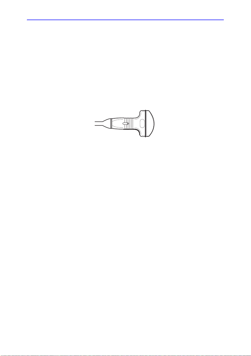
Preparing for Surgery/Intra-operative Procedures (continued)
To ensure a sterile environment during the procedure, it is
recommended that this be a two-person job.
1. Perform a high level disinfection of the probe.
2. The scanner (surgeon, sonographer, etc.) should be sterile
and gloved.
3. Place an adequate amount of sterile coupling gel on the
face of the probe.
4. Place the proper sterile sheath over the prob e and cord .
Figure 1-44. Applying Sterile Sheath
5. Depending on the type of procedure, use either sterile water
or sterile gel on the sheath cover.
Probes
NOTE: Follow your institutions guidelines on post surgery/
intra-operative procedures for probe cleaning and disinfection.
LOGIQ E9
Direction 5454884-100 English Rev. 1
–
User Guide
1-65
Page 78

Getting Started
Scanning a New Patient
1. Press Patient.
2. Press New Patient on the Patient menu.
3. If there are images on the clipboard, a pop -u p me n u
appears. Specify whether you want to store images
permanently, delete images, or go to active images.
4. Choose the exam category.
5. Verify the dataflow.
NOTE: DO NOT use the removable media Dataflows on the New
Patient menu.
NOTE: The system can display a warning dialog when the patient is
registered to “No Archive”. If the “W arn register to No
Archive” preset is selected in the Utility -> Connectivity ->
Miscellaneous menu, a warning displays. A different
dataflow for permanent storage of patient data should be
selected.
Beginning an Exam
1-66
6. Fill in patient information.
NOTE: You can also select a patient from the patient database at
the bottom of the Patient menu if the patient has a patient
ID.
Columns drive the ordering of the patients displayed. The
column that you select drives the order of the displayed
patient database.
NOTE: Do not use the following characters when filling in patient
information:
“ ‘ \ / : ; . , * < > | + = [ ] &
7. Select Register.
8. Select the probe to start scanning (or select Exit, Esc, Scan,
or Freeze).
9. Perform the exam.
LOGIQ E9
Direction 5454884-100 English
–
User Guide
Rev. 1
Page 79

Scanning a New Patient (continued)
HINTS
CAUTION
10. Store the images/loops to the clipboard.
To store the still image, press Freeze and run the cineloop
using the Trackball. Select the frame and press P1 (or the
assigned Print key).
To stor e th e cine lo op , press Freeze and run the cineloop
using the Trackball. Select the start/end frame and run the
selected loop. Press P1 (or the assigned Print key).
When you press a Print key during scan (Live Store), the
LOGIQ E9 stores the cine for the specified lengt h of tim e
noted in the T ime Span(s) preset, found und er T im e-Based
Store in Utility -> Ap plication -> Print Controls.
When you press a Print key during scan (Live Store) with
ECG, the LOGIQ E9 stores the cine for the specified
number of heart cycles noted in the Number of heart cycles
preset, found under ECG-Based Store in Utility ->
Application -> Print Controls.
If you set the Number of heart cycles for more than 1 heart
cycle in Utility -> Application -> Print Controls, the LOGIQ
E9 stores the cine for the length of time specified in “Time
Sp an(s) x Number of heart cycles”.
Refer to Chapter 16 for more information on image
storage.
Beginning an Exam
NOTE: Return to the patient screen aut omatically from the scan
LOGIQ E9
Direction 5454884-100 English Rev. 1
–
User Guide
1 1. When you have completed the study, press End Exam. The
image management screen displays. Select the im ages (still
frame or cineloop) you want to store or select Select All to
store all images. Select Permanent Store to store the
images permanently.
After completing the measureme nt, verify that the
measurement result window is updated before you send or
save the image.
screen when you select OK from the “ID is not unique”
warning message.
1-67
Page 80

Getting Started
Patient Screen
Figure 1-45. Patient Screen (Example: Category OB)
1. Image Management
2. Function Selection
3. EZBackup/EZMove
4. Dataflow Selection
5. Exit
6. Patient Information
7. Category Selection
8. Exam Information
9. Scan Assistant Program
10. Patient View/Exam View
1-68
LOGIQ E9
Direction 5454884-100 English
–
User Guide
Rev. 1
Page 81

Patient Screen (continued)
Enter Patient Data with the alphanumeric keyboard.
To navigate through the Patient Entry menu, use the Tab key or
Trackball and Set to move and fix the cursor.
Image Management
• Patient–Provides a search and creation of patient. (currently
selected)
• Image History–Provides a list of images per exam for the
currently selected patient.
• Active Images–Provides preview of the currently selected
exam and Compare Assistant.
• Data Transfer–Provides an interface to handle patient data
from a remote device.
Function Selection
• New Patient–Used to clear patient entry screen in order to
input a new patient’s data into the database.
• Register–Used to enter new patient information into the
database prior to the exam.
NOTE: If you are using the auto-generate Patient ID feature, do not
select Register. It is always a good practice to Register all
patients.
Beginning an Exam
• Details–Select the Details box to activate/deactivate the
exam details. Exam details include Indications, Comments,
Admission Number, Performing Physician’s Telephone
Number, Referring Physician’s Telephone Number , Operator
Telephone Number, and Exam Description.
NOTE: The Exam Description pull-down selection is used as the
DICOM identifier.
LOGIQ E9
Direction 5454884-100 English Rev. 1
–
User Guide
1-69
Page 82

Getting Started
WARNING
EZBackup/EZMove
Dataflow Selection
NOTE: If you use a DVD-R, select DICOM CD Read in Dataflow.
One-step method to backup (move and delete patient images)
to an external media.
Select the appropriate dataflow.
If you place the cursor on the icon, the pop-up menu displays
disk capacity.
Figure 1-46. Dataflow Pop-up
Ensure you have selected a dataflow. If No Archive is selected,
no patient data is saved. A Ø appears next to Dataflow if No
Archive is selected.
Exit
1-70
Used to exit the Patient Menu.
Direction 5454884-100 English
LOGIQ E9
–
User Guide
Rev. 1
Page 83

Patient Information
Category Selection
Beginning an Exam
• Patient ID Number
• Patient Name–Last, First and Middle
• Alternate (Other, Second) Patient ID Name and Number.
The system now allows you to enter a second identification
number for the same patient, which may be required in
certain countries. This is only displayed if enabled on the
Connectivity -> Miscellaneous screen.
• DOB (Birthdate)
• Age (automatically calculated when birthdate is input)
• Sex
Select from 8 exam application categories: Abdomen,
Obstetrics, Gynecology, Cardiology, Vascular, Urology, Small
Parts, or Pediatrics.
When a category is selected, the measurement and category
presets are displayed.
Exam Information
Shows the Current/Active Exam information. Information
pertinent to the selected exam category appears in the window.
All possible information needs to be entered.
• Images–Displays the selected exam’s images.
• Clear–Clears existing data.
• Past Exam (only for OB)–Input past exam data (register the
patient before using).
LOGIQ E9
Direction 5454884-100 English Rev. 1
–
User Guide
1-71
Page 84

Getting Started
CAUTION
Scan Assistant Program
The Scan Assistant Program is either selected automatically or
manually, depending on the preset as configured on the
Utility--> System--> General page.
To avoid patient identification errors, always verify the
identification with the patient. Make sure the correct patient
identification appears on all screens and hard copy prints.
Patient View/Exam View
• Patient View
NOTE: Use Ctrl + A to select all from the Data Transfer list/Patient
NOTE: When you double-click the patient on the patient list using
Lists the patients in the database.
view.
the Set key, the Review screen or New Exam entry screen
displays depending on the preset. You set this preset via
Select Review or New Exam in Utility -> Connectivity ->
Miscellaneous -> “Double click on patient list to start” p reset.
• Search key–select search item from Patient ID, Last
Name, First Name, Other ID, Birthdate, Sex, Exam
Date, Exam Today, Accesstion Number, Exam
Description, Exam Date Before, Exam Date Between ,
Exam Date After, Locked (Y, N) or Img. Archived (Y, N).
NOTE: If “Exam Date Between” is selected, the Input Dialog
displays and you can select the date from the displayed
calender.
NOTE: If “Exam Date Between” is used for the Search key, the
From and To dates are separated by a “-” (dash) in the
Search String.
NOTE: Img. Archived means that the exam was backed up to
external media by EZBackup or Export.
1-72
LOGIQ E9
Direction 5454884-100 English
–
User Guide
Rev. 1
Page 85

Patient View/Exam View (continued)
CAUTION
• String–enter appropriate information.
If you select Locked (Y, N) or Archived (Y, N) for the
Search key, enter Y (Yes) or N (No).
• Clear–Clears the entered string.
• Listing XX of XXX -- Displays the quantity of patients
that match the search criteria in the search window and
the quantity of patients in the database.
• Review–Select Patient/Exam for review.
• Resume Exam–Continues the exam for that patient if
you select the last exam of the day.
• New Exam–Creates a new exam based on a current or
searched patient.
• Delete–Deletes Patient/Exam.
NOTE: “Delete” is only displayed when you login as
Administrator.
• Lock/Unlock–Locks the exam/patient. Prevents move
and delete functions.
Beginning an Exam
• Exam View
Displays the Exam History of the selected patient by date .
• Disk - Displays the disk name on which you saved the
exam’s image data. If “+” displays behind t he disk name,
the data is saved on two or more disks.
To avoid patient identification errors, always verify the
identification with the patient. Make sure the correct patient
identification appears on all screens and hard copy prints.
LOGIQ E9
Direction 5454884-100 English Rev. 1
–
User Guide
1-73
Page 86

Getting Started
CAUTION
Patient Screen (continued)
Maintaining the Patient Database
To maintain optimum system performance and to safeguard
patient data, keep the total number of patients in the database
below 1,000.
To reduce the total number of patients in the dat abase, perform
the following procedure.
1. Before starting EZBackup, select “Unlock All” on the
Utility -> Admin -> Logon screen.
Prepare the unformatted CD- R or DVD-R before EZBackup.
NOTE: Pre-formatted CD-R or DVD-R cannot be used for
EZBackup.
2. First perform EZBackup and then Backup (Patient Archive
and Report Archive).
3. Go to the patient screen, select the patients/exams to
delete. Select “Delete” to delete the selected data.
NOTE: Removing image data with the “EZMove” fun ction does not
reduce the patient number in th e database.
NOTE: Ensure that all patients are exported or backed up BEFORE
deleting them.
We recommend attaching the patient list to the EZBackup
media. Insert the media and select DICOM CD Read for the
dataflow (if you use a USB drive, select DICOM USB Drive
Read). Press the right Set key to select the patient. Press the
left Set key to bring up the print menu. Select Print and press
the right Set key to print the patient list.
1-74
LOGIQ E9
Direction 5454884-100 English
–
User Guide
Rev. 1
Page 87

Chapter 2
Performing an Exam
Optimizing the Image and Measurement and Analysis
LOGIQ E9
Direction 5454884-100 English Rev. 1
–
User Guide
2-1
Page 88

Performing an Exam
B-Mode Controls
Optimizing the Image
Table 2-1: B-Mode Controls
Possible
Control
Depth Y es Depth controls the distance over which the B-Mode images anatomy .
Gain No B-Mode Gain increases or decreases the amount of echo
Focus Yes Increases the number of focal zones or moves the focal zone(s) so
Auto Optimize No Auto Optimize (Auto) lets you optimize the image based upon a the
Bioeffect
To visualize deeper structures, increase the depth. If there is a large
part of the display which is unused at the bottom, decrease the
depth.
information displayed in an image. It may have the effect of
brightening or darkening the image if sufficient echo information is
generated.
that you can tighten up the beam for a specific area. A graphic caret
corresponding to the focal zone position(s) appears on the right
edge of the image.
actual B Mode image data (Auto Tissue Optimize, ATO). The preset
levels (Low, Medium, and High) allow you to pick a preference for
the contrast enhancement in the resulting image. Low does the least
amount of contrast enhancement, high does the most.
Auto is available in single or multi image, on live, frozen or CINE
images (in B-Mode only), while in zoom, and in Spectral Doppler.
Auto in PW Doppler Mode optimizes the spectral data. Auto adjusts
the Velocity Scale (live imaging only), baseline shift, dynamic range,
and invert (if preset). Upon deactivation, the spectrum is still
optimized.
Description/
Benefit
Mode Cursor No Displays the M/D-Mode cursor on the B-Mode image.
2-2
LOGIQ E9
Direction 5454884-100 English
–
User Guide
Rev. 1
Page 89

Optimizing the Image
Table 2-1: B-Mode Controls (Continued)
Possible
Control
SRI-HD No SRI-HD (Speckle Reduction Imaging High Definition) is an adaptive
CrossXBeam No CrossXBeam is the process of combining three or more frames from
Coded Harmonic
Imaging (CHI)
Frequency Yes Multi Frequency mode lets you downshift to the probe's next lower
Bioeffect
algorithm to reduce the unwanted effects of speckle in the
ultrasound image. Image speckle usually appears as a grainy
texture in otherwise uniform areas of tissue. Its appearance is
related to image system characteristics, rather than tissue
characteristics, so that changes in system settings, such as probe
type, frequency, depth, and others, can cange the appearance of the
speckle. Too much speckle can impair image quality and make it
difficult to see the desired detail in the image. Likewise, too much
filtering of speckle can mask or obscure desired image detail. Extra
care must be taken to select the optimal SRI-HD level. SRI-HD is
available in B-Mode imaging and may be used with any transducer
or clinical application when image speckle appears to interfere with
the desired image detail.
different steering angles into a single frame. CrossXBeam is
available on Convex and Linear probes.
CrossXBeam combines multiple co-planar images from different
view angles into a single image at real-time frame rates, using
bi-cubic interpolation.
Yes Harmonic imaging utilizes Digitally Encoded Ultrasound (DEU).
Coded Harmonics enhances near field resolution for improved small
parts imaging as well as far field penetration.
frequency or shift up to a higher frequency.
Description/
Benefit
Steer Yes You can slant the B-Mode or Color Flow linear image left or right to
get more information without moving the probe. The angle steer
function only applies to linear probes.
Virtual Convex Yes On Linear and Sector probes, Virtual Convex provides a larger field
of view in the far field. Virtual Convex is always active with Sector
probes.
TGC No TGC amplifies returning signals to correct for the attenuation caused
Width Y es Y ou can widen or narrow the size of the sector angle to maximize the
Tilt Yes You can steer the sector angle to get more information without
LOGIQ E9
–
User Guide
by tissues at increasing depths. TGC slide pots are spaced
proportionately to the depth. The area each pot amplifies varies as
well. A TGC curve may appear on the display (if preset), matching
the controls that you have set (except during zoom). You can choose
to deactivate the TGC curve on the image.
image's region of interest (ROI).
moving the probe while in B-Mode, M-Mode, Doppler Mode, and
Color Flow Mode. Tilt is not available on Linear probes.
Direction 5454884-100 English Rev. 1
2-3
Page 90

Performing an Exam
Table 2-1: B-Mode Controls (Continued)
Possible
Control
Dynamic Range No Dynamic Range controls how echo intensities are converted to
Reverse (if Preset) No Flips the image 180 degrees left/right.
Line Density Yes Optimizes B-Mode frame rate or spatial resolution for the best
Maps No The system supplies B, M, and Doppler Mode system maps.
Frame Average No Temporal filter that averages frames together, thereby using more
Colorize No Colorize is the colorization of a conventional B-Mode image or
Bioeffect
shades of gray, thereby increasing the adjustable range of contrast.
The Dynamic Range control name changes to Compression on
frozen images.
possible image.
pixels to make up one image. This has the effect of presenting a
smoother, softer image.
Doppler Spectrum to enhance the user's ability to discern B, M, and
Doppler Mode intensity valuations. Colorize is NOT a Doppler Mode.
NOTE: You can colorize realtime or CINE images or Timeline CINE,
but not DVR images.
Colorizes the gray scale image to enhance the eye's discrimination
capability . S pectrum Colorize colorizes the spectrum as a function of
power using the inverse of the Colorize map for the signal intensity in
each Doppler line. Colorize enhances the visibility of the spectrum's
characteristics and enhances your ability to identify spectral
broadening and the edge contours of the spectrum used to define
the peak frequency/velocity.
The gray bar displays while Colorize is activated.
Description/
Benefit
Rotation No Flips the image 180 degrees up/down.
CAUTION: When reading a rotated image, be careful to observe the
probe orientation to avoid possible confusion over scan direction or
left/right image reversal.
Rejection No Selects a level below which echoes will not be amplified (an echo
must have a certain minimum amplitude before it will be processed).
Suppression No Suppresses the noise in the image.
Speed of Sound No Changes the transmitted speed of sound for various tissue types.
2-4
LOGIQ E9
–
User Guide
Direction 5454884-100 English
Rev. 1
Page 91

Color Flow Mode Controls
Color Flow Mode and Color M-Mode are Doppler Modes
intended to add color-coded qualitative information concerning
the relative velocity and direction of fluid motion within the
B-Mode or M-Mode image.
Table 2-2: Color Flow Mode Controls
Optimizing the Image
Possible
Control
Flow Model
Shortcuts
Gain No Gain amplifies the overall strength of echoes processed in the Color
Scale (Velocity
Scale)
Wall Filter No Filters out low flow velocity signals. It helps get rid of motion artifacts
Color Width Yes Color Width sizes and positions the color window.
Invert (Color Invert) No Lets you view blood flow from a different perspective, e.g., red away
Baseline No Changes the Color Flow or Doppler spectrum baseline to
Angle Steer Yes You can slant the ROI of the Color Flow linear image left or right to
Bioeffect
No In certain applications, you can quickly select the flow state via a
shortcut on the Color Flow Mode Touch Panel menu.
Flow window or spectral Doppler timeline.
Yes Increases/decreases the Scale on the color bar.
caused from breathing and other patient motion.
(negative velocities) and blue toward (positive velocities). You can
invert a real-time or frozen image.
NOTE: Invert reverses the color map, NOT the color Scale.
accommodate higher velocity blood flow. Minimizes aliasing by
displaying a greater range of forward flow with respect to reverse
flow, or vice versa.
Baseline adjusts the alias point. The default baseline is at the
midpoint of the color display and at the midpoint of the color bar
reference display.
get more information without moving the probe. The Angle Steer
function only applies to linear probes.
Description/
Benefit
Accumulation No Accumulation enhances the flow in an image.
Color Flow Line
Density
Map No Allows you to select a specific color map. After you have made your
Threshold No Threshold assigns the gray scale level at which color information
Frame Average No Averages color frames.
Transparency Map No Brings out the tissue behind the color map.
LOGIQ E9
–
User Guide
Y es Optimizes the Color Flow frame rate or spatial resolution for the best
Available in Contrast, Color Flow, and PDI.
possible color image.
selection, the color bar displays the resultant map.
stops.
Direction 5454884-100 English Rev. 1
2-5
Page 92

Performing an Exam
Table 2-2: Color Flow Mode Controls (Continued)
Possible
Control
Spatial Filter No Smooths out the color, makes it look less pixely.
Flash Suppression No Activates/deactivates Flash Suppression, a motion artifact
Sample Vol (Sample
Volume)
Sample Volume
Length (SV Length)
Packet Size Yes Controls the number of samples gathered for a single color flow
Map Compress No When you increase the value, high velocity elements in the map are
CF/PDI Vertical Size No You can set the default CF/PDI ROI vertical size.
CF/PDI Width No You can set the default CF/PDI ROI width.
CF/PDI Center
Depth
CF/PDI Frequency
(MHz)
Bioeffect
elimination process.
Y es Places the sample volume gate on the Color Flow image. The gate is
positioned over a specific position within the vessel.
Yes Sizes the sample volume gate.
vector.
compressed so that the map darkens. When you decrease the
value, low velocity elements in the map are compressed so that the
map lightens. The effect is visible in the color bar.
No You can set the default CF/PDI center depth.
No You can set the default CF/PDI Frequency (MHz).
Description/
Benefit
CF/PDI Auto
Frequency
CF/PDI Focus Depth
(%)
Power Doppler
Imaging (PDI)
No You can set the default CF/PDI Auto Frequency.
No You can set the default CF/PDI center depth.
No Power Doppler Imaging (PDI) is a color flow mapping technique
used to map the strength of the Doppler signal coming from the flow
rather than the frequency shift of the signal. Using this technique, the
ultrasound system plots color flow based on the number of reflectors
that are moving, regardless of their velocity. PDI does not map
velocity, therefore it is not subject to aliasing.
2-6
LOGIQ E9
–
User Guide
Direction 5454884-100 English
Rev. 1
Page 93

M-Mode Controls
Optimizing the Image
Table 2-3: M-Mode Controls
Possible
Control
Sweep Speed Yes Changes the speed at which the timeline is swept.
Anatomical M-Mode Yes Anatomical M-Mode gives you the ability to manipulate the cursor at
Bioeffect
Available in M-Mode, Doppler Mode and M Color Flow Mode.
different angles and positions. The M-Mode display changes
according to a motion of the M cursor.
Curved Anatomical M-Mode (CAMM) displays a distance/time plot
from a free-drawn cursor line. CAMM is available in gray scale, color
and TVI.
Description/
Benefit
M Color Flow Mode
See ‘Color Flow Mode Controls’ on page 2-5.
LOGIQ E9
–
User Guide
Direction 5454884-100 English Rev. 1
2-7
Page 94

Performing an Exam
Doppler Mode Controls
Table 2-4: Doppler Mode Controls
Possible
Control
Update Yes Toggles between simultaneous and update presentation while
SV Length
(Trackball)
Doppler sample
volume length (SV
Length)
Scale (Velocity
Scale)
Angle Correct/Auto
Angle
Quick Angle No Quickly adjusts the angle by 60 degrees.
Wall Filter No Insulates the Doppler signal from excessive noise caused from
Bioeffect
viewing the timeline.
Yes Moves the sample volume gate on the B-Mode's Doppler Mode
cursor. The gate is positioned over a specific position within the
vessel.
Yes Sizes the sample volume gate.
Yes Adjusts the velocity scale to accommodate faster/slower blood flow
velocities. Velocity scale determines pulse repetition frequency.
If the sample volume gate range exceeds single gate Scale
capability, the system automatically switches to high PRF mode.
Multiple gates appear, and HPRF is indicated on the display.
No Estimates the flow velocity in a direction at an angle to the Doppler
vector by computing the angle between the Doppler vector and the
flow to be measured.
NOTE: When the Doppler Mode Cursor and angle correct indicator
are aligned (the angle is O), you cannot see the angle correct
indicator.
vessel movement.
Description/
Benefit
Baseline No Adjusts the baseline to accommodate faster or slower blood flows to
eliminate aliasing.
Mode Cursor No Displays the Doppler Mode cursor on the B-Mode image.
Steer and Fine Steer Yes You can slant the ROI of the Color Flow linear image left or right to
Audio Volume No Controls audio output.
Invert No Vertically inverts the spectral trace without affecting the baseline
Compression
(Dynamic Range)
Trace Method
(Spectral Trace)
Cycles to Average No The average value over a number of cycles (from 1-5).
Trace Sensitivity No Adjust the trace to follow the waveform for signal strength.
No Dynamic range controls how echo intensities are converted to
No Traces the average mean and peak velocities in realtime or frozen
2-8
get more information without moving the probe. The angle steer
function only applies to linear probes.
position.
shades of gray, thereby increasing the range of contrast you can
adjust.
images.
LOGIQ E9
Direction 5454884-100 English
–
User Guide
Rev. 1
Page 95

Optimizing the Image
Table 2-4: Doppler Mode Controls (Continued)
Possible
Control
Trace Direction No Specifies trace direction.
Cursor Moving No Cursor Moving lets you ‘walk’ Doppler through a vessel while the
Display Format No Changes the horizontal/vertical layout between B-Mode and
Modify Auto Calcs No Activates the menu to select which calculations are automatically
Auto Calcs No Activates the calculation automatically which you select in the Modify
Bioeffect
Doppler gate is moving.
M-Mode, or timeline only.
calculated.
Auto Calculation when the system is in a state of freeze or live.
Description/
Benefit
LOGIQ E9
–
User Guide
Direction 5454884-100 English Rev. 1
2-9
Page 96

Performing an Exam
3D Mode
3D Type Description Sensor/No Sensor Available Tabs
Table 2-5: 3D Package Options
Easy 3D Designed for rendering
B Mode and Color Flow
Mode images, e.g.,
Baby Face scans.
Advanced 3D Designed for rendering
B Mode and Color Flow
Mode images, e.g.,
vessel trees.
Tru3D (Option) Designed for rendering
B Mode and Color Flow
Mode images, e.g.,
vessel trees.
Acquiring a 3D Scan
To acquire a 3D scan,
1. Optimize the B-Mode image. Ensure even gel coverage.
2. Press the 3D control panel key. Two screens appear.
NOTE: Set appropriate values for Acq Mode and Scan Plane. Al so,
set the scan distance before scanning.
3. To start acquiring the image, press Start (Trackball key).
4. T o perform a parallel scan, scan evenly. To perform a sweep
(fan) scan, rock the probe once. Note the distance of the
scan.
5. The 3D volume of interest (VOI) is dynamically assembled
on the right side of the screen.
NOTE: If the image stops before you’re done scanning, start
acquiring the 3D volume of interest again.
No sensor 3D Acquisition, Easy
3D, Movie
No sensor 3D Acquisition, Easy
3D, Advanced 3D,
Movie
Sensor 3D Acquisition, Easy
3D, Advanced 3D,
Movie, Tru3D
2-10
6. To complete the 3D scan, press End (Trackball key).
NOTE: You can al so pr ess Fr ee ze , bu t th en you need to also pr ess
the 3D key to obtain the final render.
LOGIQ E9
Direction 5454884-100 English
–
User Guide
Rev. 1
Page 97

Other Controls
Acoustic
Output
Hazard
Trackball Key Map
Zoom
Optimizing the Image
The current mapping is shown on the trackball mapping display
area in the lower, right-hand corner of the display screen. Four
Trackball keys surround the Trackball. These Trackball keys are
mapped based on the current state of the system (live imaging,
frozen imaging, measurements, etc.)
Trackball functionality is labeled on t he display. To activate new
functionality for the Trackball, press the correct key adjacent to
the Trackball, as indicated on the display.
Write zooming an image changes the frame rate which tends to
change thermal indices. The position of the focal zones may
also change which may cause the peak intensity to occur at a
different location in the acoustic field. As a result, the MI (TI)
may change.
Observe the output display for possible effects.
To zoom an image, adjust Zoom. A reference image appears in
the lower , left-hand section of the display.
To exit zoom, adjust Zoom until the reference zoom image is
removed or press B-Mode.
LOGIQ E9
Direction 5454884-100 English Rev. 1
–
User Guide
2-11
Page 98

Performing an Exam
Split Screen
Dual Caliper
Freezing an image
To activate a dual split screen, press L or R.To activate a quad
display, press and hold down L.
When you activate Split Screen by pressing L, the single image
is placed on the left side; when you activate Split screen by
pressing R, the single image is placed on the right side.
To switch between active images, press L/R.
To deactivate, press R until the screen changes.
In split screen, you can draw a caliper, area, ellipse, or spline
trace on both the left and right image at the same time.
Whichever side of the screen that you annotate is called the
“Original” graphic. The copy is called the “Shadow” graphic.
To freeze an image,
NOTE: Deactivating Freeze erases all measurements and calculations
Activating CINE
1. Press Freeze. The Freeze key backlight turns green.
If you are in a mixed mode, both screen formats stop
immediately. Deactivating Freeze restarts both modes and
places a black bar on the trace to indicate the time d iscontinuit y.
To reactivate the image,
1. Press Freeze again.
from the display (but not from the worksheet).
Use the Trackball to start CINE after pressing Freeze.
To activate CINE,
1. Press Freeze.
2. Move the Trackball.
2-12
LOGIQ E9
Direction 5454884-100 English
–
User Guide
Rev. 1
Page 99

Body Patterns
Optimizing the Image
To activate body patterns, press the Body Pattern/Ellipse
control. A maximum of 6 body pattern packages are displayed
on the Touch Panel according to exam category and preset.
Select the desired body pattern on the Touch Panel. The
selected body pattern is displayed on the monitor.
Press the Move Pattern control on the Touch Panel to
reposition the body pattern with the Trackball and Set controls.
A probe mark is associated with the body patterns and illustrates
the probe position on the body pattern. This marker can be
placed with the Trackball and rotated with the Ellipse control.
The probe mark type is selectable by rotating the Probe Type
control on the Touch Panel. There are different choices available
with one being a blank selection.
To select the active side in dual B-Mode, use the Active Side
rotary control at the bottom of the Touch Panel.
To clear the body pattern, press the Body Pattern/Ellipse
control to activate body patterns and then press the Clear key.
Press Set on the keyboard or Scan on the Touch Panel to exit
without erasing the body pattern.
LOGIQ E9
Direction 5454884-100 English Rev. 1
–
User Guide
2-13
Page 100

Performing an Exam
Annotating an Image
Pressing the Comment key or any keys on the alphanumeric
keyboard initiates the comment mode. This assigns the trackball
function to controlling the cursor and displays the comment
library on the Touch Panel menu.
In comment mode, text can be added by using the comment
library or by typing from the alphanumeric keyboard.
After activating the commen t mode, a vertical bar type cursor
appears on the screen. Use the Trackball to move the cursor.
To delete comments by character, press the Backspace key.
To delete all comments and arrow marks, press the Clear key
twice immediately after entering the comment mode.
To move by words or by text group, press the Tab key.
Arrow pointers can be used by activating the F2 (Arrow) key on
the keyboard or by selecting the Comment key and then the top
Trackball key. When the pointe r comes up, it is a GREEN color,
indicating it is active and can be moved.
Using the Fast Key
A keyboard Fast Key is available to record and run a sequence
of often-run keystrokes.
To create a Fast Key, press the F5 key and follow the on-scr een
prompts.
To start a Fast Key, press the F6 key and follow the on-screen
prompts.
2-14
LOGIQ E9
Direction 5454884-100 English
–
User Guide
Rev. 1
 Loading...