

Page 1
Your Gateway
KAS-303 Home Theater
systemguide
Setting up
Troubleshooting
Page 2

Page 3

Contents
1 Checking Out Your Gateway Receiver . . . . . . . . . . . . . . . . . . . . . . . . . . . 1
Features . . . . . . . . . . . . . . . . . . . . . . . . . . . . . . . . . . . . . . . . . . . . . . . . . . . . . . . . . . . 2
Important Safeguards . . . . . . . . . . . . . . . . . . . . . . . . . . . . . . . . . . . . . . . . . . . . . . . . 2
Package contents . . . . . . . . . . . . . . . . . . . . . . . . . . . . . . . . . . . . . . . . . . . . . . . . . . . 3
Front panel . . . . . . . . . . . . . . . . . . . . . . . . . . . . . . . . . . . . . . . . . . . . . . . . . . . . . . . . 4
Display . . . . . . . . . . . . . . . . . . . . . . . . . . . . . . . . . . . . . . . . . . . . . . . . . . . . . . . . . 5
Back panel connections . . . . . . . . . . . . . . . . . . . . . . . . . . . . . . . . . . . . . . . . . . . . . . 6
Universal remote control . . . . . . . . . . . . . . . . . . . . . . . . . . . . . . . . . . . . . . . . . . . . . . 7
Inserting batteries . . . . . . . . . . . . . . . . . . . . . . . . . . . . . . . . . . . . . . . . . . . . . . . 11
2 Connecting Components and Speakers. . . . . . . . . . . . . . . . . . . . . . . . . 13
Understanding video connections . . . . . . . . . . . . . . . . . . . . . . . . . . . . . . . . . . . . . . 14
Understanding audio connections . . . . . . . . . . . . . . . . . . . . . . . . . . . . . . . . . . . . . . 15
Connecting the AM loop antenna . . . . . . . . . . . . . . . . . . . . . . . . . . . . . . . . . . . . . . 16
Connecting the FM antenna . . . . . . . . . . . . . . . . . . . . . . . . . . . . . . . . . . . . . . . . . . 17
Connecting a DVD player . . . . . . . . . . . . . . . . . . . . . . . . . . . . . . . . . . . . . . . . . . . . 18
Connecting a 6 or 7 channel component . . . . . . . . . . . . . . . . . . . . . . . . . . . . . . . . 19
Connecting a VCR . . . . . . . . . . . . . . . . . . . . . . . . . . . . . . . . . . . . . . . . . . . . . . . . . . 20
Connecting a tape component . . . . . . . . . . . . . . . . . . . . . . . . . . . . . . . . . . . . . . . . 22
Connecting an AUX component . . . . . . . . . . . . . . . . . . . . . . . . . . . . . . . . . . . . . . . 23
Connecting a television . . . . . . . . . . . . . . . . . . . . . . . . . . . . . . . . . . . . . . . . . . . . . . 24
Connecting speakers . . . . . . . . . . . . . . . . . . . . . . . . . . . . . . . . . . . . . . . . . . . . . . . . 25
Speaker placement . . . . . . . . . . . . . . . . . . . . . . . . . . . . . . . . . . . . . . . . . . . . . . 25
Making the connections . . . . . . . . . . . . . . . . . . . . . . . . . . . . . . . . . . . . . . . . . . 26
Plugging in your components . . . . . . . . . . . . . . . . . . . . . . . . . . . . . . . . . . . . . . . . . 35
3 Using the Receiver. . . . . . . . . . . . . . . . . . . . . . . . . . . . . . . . . . . . . . . . . . . . . . 37
Turning the receiver on and off . . . . . . . . . . . . . . . . . . . . . . . . . . . . . . . . . . . . . . . . 38
Setting up your speakers . . . . . . . . . . . . . . . . . . . . . . . . . . . . . . . . . . . . . . . . . . . . 39
Adjusting the speaker settings . . . . . . . . . . . . . . . . . . . . . . . . . . . . . . . . . . . . . 39
Using the universal remote control . . . . . . . . . . . . . . . . . . . . . . . . . . . . . . . . . . . . . 42
Operating components with the universal remote control . . . . . . . . . . . . . . . . 42
Programming the remote control . . . . . . . . . . . . . . . . . . . . . . . . . . . . . . . . . . . 43
Switching between connected components . . . . . . . . . . . . . . . . . . . . . . . . . . . . . . 46
Surround sound . . . . . . . . . . . . . . . . . . . . . . . . . . . . . . . . . . . . . . . . . . . . . . . . . . . . 47
Surround modes . . . . . . . . . . . . . . . . . . . . . . . . . . . . . . . . . . . . . . . . . . . . . . . . 47
Selecting the surround mode . . . . . . . . . . . . . . . . . . . . . . . . . . . . . . . . . . . . . . 50
Adjusting the channel levels . . . . . . . . . . . . . . . . . . . . . . . . . . . . . . . . . . . . . . . 52
Storing channel levels in memory . . . . . . . . . . . . . . . . . . . . . . . . . . . . . . . . . . 53
i
Page 4

Adjusting the LFE level . . . . . . . . . . . . . . . . . . . . . . . . . . . . . . . . . . . . . . . . . . .54
Adjusting the tone . . . . . . . . . . . . . . . . . . . . . . . . . . . . . . . . . . . . . . . . . . . . . . .55
Compressing the dynamic range . . . . . . . . . . . . . . . . . . . . . . . . . . . . . . . . . . . .55
Adjusting Dolby Pro Logic II Music parameters . . . . . . . . . . . . . . . . . . . . . . . .56
Listening to the radio . . . . . . . . . . . . . . . . . . . . . . . . . . . . . . . . . . . . . . . . . . . . . . . .57
Selecting the tuner . . . . . . . . . . . . . . . . . . . . . . . . . . . . . . . . . . . . . . . . . . . . . . .57
Manual tuning . . . . . . . . . . . . . . . . . . . . . . . . . . . . . . . . . . . . . . . . . . . . . . . . . . .57
Auto tuning . . . . . . . . . . . . . . . . . . . . . . . . . . . . . . . . . . . . . . . . . . . . . . . . . . . . .58
Memorizing radio stations . . . . . . . . . . . . . . . . . . . . . . . . . . . . . . . . . . . . . . . . .58
Tuning to preset stations . . . . . . . . . . . . . . . . . . . . . . . . . . . . . . . . . . . . . . . . . .59
Analog Audio/Video recording . . . . . . . . . . . . . . . . . . . . . . . . . . . . . . . . . . . . . . . . .59
Digital Audio recording with an MD recorder . . . . . . . . . . . . . . . . . . . . . . . . . . . . . .61
Using the sleep timer . . . . . . . . . . . . . . . . . . . . . . . . . . . . . . . . . . . . . . . . . . . . . . . .62
Adjusting the display brightness . . . . . . . . . . . . . . . . . . . . . . . . . . . . . . . . . . . . . . . .62
4 Using the OSD. . . . . . . . . . . . . . . . . . . . . . . . . . . . . . . . . . . . . . . . . . . . . . . . . . .63
Displaying the current status . . . . . . . . . . . . . . . . . . . . . . . . . . . . . . . . . . . . . . . . . .64
Using the Menu screen . . . . . . . . . . . . . . . . . . . . . . . . . . . . . . . . . . . . . . . . . . . . . .65
OSD menus and options . . . . . . . . . . . . . . . . . . . . . . . . . . . . . . . . . . . . . . . . . .66
5 Maintaining and Troubleshooting Your Receiver . . . . . . . . . . . . . . . .69
Cleaning and maintenance . . . . . . . . . . . . . . . . . . . . . . . . . . . . . . . . . . . . . . . . . . . .70
Troubleshooting . . . . . . . . . . . . . . . . . . . . . . . . . . . . . . . . . . . . . . . . . . . . . . . . . . . .70
Initializing the receiver . . . . . . . . . . . . . . . . . . . . . . . . . . . . . . . . . . . . . . . . . . . .72
Technical support . . . . . . . . . . . . . . . . . . . . . . . . . . . . . . . . . . . . . . . . . . . . . . . . . . .73
Telephone support . . . . . . . . . . . . . . . . . . . . . . . . . . . . . . . . . . . . . . . . . . . . . . .73
Internet . . . . . . . . . . . . . . . . . . . . . . . . . . . . . . . . . . . . . . . . . . . . . . . . . . . . . . . .73
A Specifications and Setup Codes. . . . . . . . . . . . . . . . . . . . . . . . . . . . . . . . .75
Specifications . . . . . . . . . . . . . . . . . . . . . . . . . . . . . . . . . . . . . . . . . . . . . . . . . . . . . .76
LN-520 receiver specifications . . . . . . . . . . . . . . . . . . . . . . . . . . . . . . . . . . . . . .76
KAS-303 speakers specifications . . . . . . . . . . . . . . . . . . . . . . . . . . . . . . . . . . . .78
SW303 subwoofer specifications . . . . . . . . . . . . . . . . . . . . . . . . . . . . . . . . . . . .79
Setup Codes . . . . . . . . . . . . . . . . . . . . . . . . . . . . . . . . . . . . . . . . . . . . . . . . . . . . . . .80
TV setup codes . . . . . . . . . . . . . . . . . . . . . . . . . . . . . . . . . . . . . . . . . . . . . . . . .80
VCR setup codes . . . . . . . . . . . . . . . . . . . . . . . . . . . . . . . . . . . . . . . . . . . . . . . .85
DVD setup codes . . . . . . . . . . . . . . . . . . . . . . . . . . . . . . . . . . . . . . . . . . . . . . . .91
Cable Set-top Box setup codes . . . . . . . . . . . . . . . . . . . . . . . . . . . . . . . . . . . . .92
Satellite Set-top Box setup codes . . . . . . . . . . . . . . . . . . . . . . . . . . . . . . . . . . .95
Aux-Tape/MiniDisc setup codes . . . . . . . . . . . . . . . . . . . . . . . . . . . . . . . . . . . . .96
Aux-Laserdisc setup codes . . . . . . . . . . . . . . . . . . . . . . . . . . . . . . . . . . . . . . . .96
Aux-Tape setup codes . . . . . . . . . . . . . . . . . . . . . . . . . . . . . . . . . . . . . . . . . . . .96
ii
Page 5

Aux-Amplifier setup codes . . . . . . . . . . . . . . . . . . . . . . . . . . . . . . . . . . . . . . . . 97
Aux-Home Automation setup codes . . . . . . . . . . . . . . . . . . . . . . . . . . . . . . . . . 98
Aux-DBS setup codes . . . . . . . . . . . . . . . . . . . . . . . . . . . . . . . . . . . . . . . . . . . . 98
Aux-Accessory setup codes . . . . . . . . . . . . . . . . . . . . . . . . . . . . . . . . . . . . . . . 99
CD setup codes . . . . . . . . . . . . . . . . . . . . . . . . . . . . . . . . . . . . . . . . . . . . . . . . 99
B Safety, Regulatory, and Legal Information . . . . . . . . . . . . . . . . . . . . . 103
Index. . . . . . . . . . . . . . . . . . . . . . . . . . . . . . . . . . . . . . . . . . . . . . . . . . . . . . . . . . . . . . 111
iii
Page 6

iv
Page 7

Checking Out
Your Gateway
Receiver
This chapter provides basic information about your
Gateway Receiver.
Read this chapter to le arn about:
■ Warnings and safeguards
■ Controls an d connections
■ Remote control
1
1
Page 8

Chapter 1: Checking Out Yo ur Gateway Receiver
Features
A powerful, 1000-watt, 6.1 home theater system featuring TrueDigital™
amplification for premium, multichannel digital sound.
■ 600-watt audio receiver
■ 400-watt Hsu Research
■ 5 satellite and 1 Ventriloquist
■ Analog and digital audio inputs and ou tputs.
■ Composite and S-Video video inputs and output s.
™
-engineered sub-woofer
Important Safeguards
Warning Risk of electric shock - Do not open
To reduce the risk of electric shock, do no remove the
cover. There are no user-serviceable parts inside.
Removing the cover voids the warranty.
Have y our receiv er repaired b y qualified service person nel
only.
™
center channel speakers
Warnings an d precautions
■ Disconnect all cables before moving your receiver. Moving your receiver
with its cables atta ched may damage the cables and cause fire or electric
shock danger.
■ Do not expose your receiver to rain or moisture.
■ Keep your receiver away from excessive dust, high temperatures, moisture,
or direct sunlight.
■ Use your receiver in a well-ventilated area and do not cover the ventilation
openings.
■ Do not modify your receiver or use an unshielded power cord or video
output source cable, or you may experience excessive interference.
2
www.gateway.com
Page 9

■ Disconnect your receiver and unplug the power cord when not used for
a long period of time.
■ For more safety information, see “Important safety information” on
page 103.
P ackage contents
Along with your receiver, the packaging box contains the following items:
■ Remote control
■ Two AAA batteries
■ RCA audio/video cables
■ AM Loop antenna
■ FM antenna
■ User guide
You can purchase these optional accessories for your receiver:
Package contents
■ S-Video cable
■ AC-3 (Toslink) cable
www.gateway.com
3
Page 10
Chapter 1: Checking Out Yo ur Gateway Receiver
Front panel
Adjust/
Tuning/Preset
Decoding/
Tuning Mode
Setup/
Memory
Power
Standby
Display
Digital Input/
AM/FM Mode
Input Selector
Item Description
Display See “Display” on page 5.
Adjust/
Tuning/Preset
Volume Turns the volume up or down.
Power Turns the receiver on and off.
Standby Lights when the receiver is in Standby mode.
When in Setup mode, adjusts submenu items.
When the tuner is selected, tunes the radio manually,
automatically, or to preset radio stations.
Volume
Headphone
jack
Input Selector Switches inputs.
Digital Input/
AM/FM Mode
Setup/
Memory
Decoding/
Tune Mode
Headphone jack Connect your headphones to this jack.
4
Digital Input selector when a digital signal (AUX, VIDEO 1-3)
is selected.
When the tuner is selected, selects the band.
Press for more than two seconds to enter Setup mode. While
in Setup mode, switches between main menu items.
When the tu ner is selec ted, memo rizes radio stations.
When in Setup mode, switches submenu items.
When the tu ner is sel ected, switch es between Tuning mode
and Preset mode.
www.gateway.com
Page 11
Display
Front panel
Stereo indicator
Main display
DTS ES DIGITAL-EX PROLOGIC II CM DSP AUTO DIGITAL SLEEP
Surround mode indicators
Tuned indicator
ST TUNED TIMER R2 DIRECT TAPE 2M PRESET
Auto mode indicator
Digital input signal indicator
Direct indicator
Memory indicator
dB
kHz
MHz
MEM 1
ft
Preset/Sleep/Distance
indicators
Item Description
Main display Displays items such as, Input source, frequency,
volume level, and operating information.
STEREO indicator Displays stereo radio signal status.
TUNED indicator Displays tuned radio station status.
DIRECT indicator Displays direct mode status.
MEMory indicator Displays the selected memory channel.
Surround mode indicators Displays the currently selected surround sound
mode.
AUTO indicator Displays automatic mode status.
DIGITAL input signal indicator Displays presence of a digital audio signal.
PRESET number, SLEEP ti me,
Speaker distance display
Displays presets, sleep timer, and speaker
distance infor mation.
www.gateway.com
5
Page 12
Chapter 1: Checking Out Yo ur Gateway Receiver
Back panel connections
Antenna
Video
6 or 7 channel direct
Digital Audio Subwoofer Speakers
Connector Array Description
Antenna Connect AM and FM antennas.
■
Video (and audio)
components
6 or 7 channel direct input
components
Digital INs and OUT
Connect the VIDEO 1-3 jacks to components, such
as a VCR or DVD player.
■
Connect the Monitor jacks to your primary and
secondary displays, such as a television or projector.
Connect the analog a udi o ou tpu ts of a 6 or 7 channel
component such as a D VD pla y er or e xternal decoder .
When connecting a 6 channel component leave the
SURR BACK jack empty.
■
Connect the Digital INs to the coaxial and optical
Digital OUTs of the components connected to AUX
and VIDEO 1-3.
■
Connect the Digita l OU T to the D ig ita l I N of a dig ita l
recorder such as an MD re corder or CD recorder that
has a digital input.
■
Audio (only) components
Connect the TAPE IN/OUT jacks to an audio
only-type component, such as a tape deck.
■
Connect the AUX jacks to an additional component
such as a C D player.
Subwoofer Connect a powered subwoo fer.
Speakers Connect speakers with an impedance of 6 ohms or
above.
6
www.gateway.com
Page 13
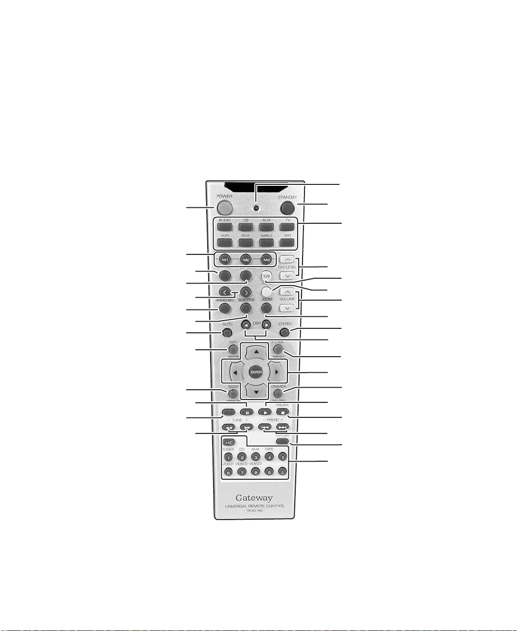
Universal remote co ntrol
Universal remote contr ol
This universal remote control can operate not only this receiver, but also most
popular brands of audio and video com ponents such as CD players, cassette
decks, TVs, cable boxes, VCRs, DVD players, and satellite receivers.
To operate up to 7 components, other than this receiver, enter the setup code
for each component. For information, see “Programming the remote control”
on page 43.
LED
POWER
MACRO
SPEAKER SETUP
PL II MUSIC PARAMETER
ADJUST
AUDIO SELECT
SUBTITLE
AUTO
OSD/SETUP
SLEEP/DISPLAY
REVERSE PLAY/PAUSE
RECORD
TUNE/SEARCH
STANDBY
DEVICE
CHANNEL/LEVEL
CHANNEL SELECT/T/V
MUTE
VOLUME
ZOOM
STEREO
DSP MODE
TEST TONE/MENU
Navigation/ENTER
DIMMER/RETURN
PLAY
P.SCAN
PRESET/SKIP
7 CH DIRECT
Numeric keypad (0-9 , 10+)/
Direct INPUT sel ector
www.gateway.com
7
Page 14

Chapter 1: Checking Out Yo ur Gateway Receiver
L
L
E
Button Description
POWER
STANDBY
CH/LEVE
CH/LEVE
CH SEL
T/V
MUTE
VOLUME
VOLUME
Power On. Turns the receiver off or puts the receiv er in Standb y mode. F or more
information, see “Turning the receiver on and off” on page 38.
LED. Provides visual feedback when perfor ming functions or programming
operations.
Standby. T urns the receiv er on or puts the receiver in Standby mode. Fo r more
information, see “Turning the receiver on and off” on page 38.
Device. Press to put the remote into a specific device mode for operating
connected component s. F or more inf ormation, see “O perating co mponents with
the universal remote control” on page 42.
Channel level. Adjust s a prog r am (television) channel or the test tone channel
levels up or down. For more infor mation, see “Adjusting the channel levels” on
page 52.
Channel select. Selects a specific channel to adjus t individual test tone ch annel
levels up or down. For more infor mation, see “Adjusting the channel levels” on
page 52.
T/V. Changes inputs for connected components such as a TV or VCR.
Mute. Mutes the sound.
Volume. Adjusts the overall volume.
ZOOM
STEREO
Zoom. Enlarges a part of the DVD screen.
Stereo. Turns off surround mode and puts the receiver into stereo mode. For
more information, see “Selecting the surround mode” on page 50.
DSP
T. T ON
MENU
DSP Mode. Cycles through the available surround modes. For more
information, see “Selecting the surround mode” on page 50.
Test tone. Enters the test tone mode. For more information, see “Adjusting the
channel levels” on page52.
Menu. Opens the menu for connected components such as a DVD player.
, , , . Navigates the on-screen display (OSD) menus. For more
information, see “Using the OSD” on page 63.
8
www.gateway.com
Page 15
Button Description
.
Universal remote co ntrol
ENTER
DIMMER
RETURN
P.SCAN
- PRESET +
7CH DIR
Enter. Confirms a selection in a menu. For more information, see “Using the
OSD” on page 63.
Dimmer. Adjusts the display brightness. For more information, see “Adjusting
the display brightness” on page62.
Return. Returns from an OSD settings screen to the Setup Menu. For more
information, see “Using the OSD” on page 63.
Play ( ). Plays the DVD, CD, or MP3.
P.Scan. Scans the preset radio stations pausing at each one for 5 seconds.
For more inform ation, se e “Liste ning to th e radio” on page 57.
Stop ( ).
Stops playing the disc.
Preset/Skip back ( ). Changes the radio station to the ne xt memo rized stati on
or performs bac kward skip functions such as skipping bac k one CD trac k or D VD
chapter. For more infor mation, see “Listening to the radio” on page 57.
Preset/Skip ahead ( ). Changes the radio station to the previous memorized
station or perf orms f o rw ard s kip func tions suc h as skip ping a head one CD tr ac k
or DVD chapter. For more infor m ation , s ee “ Li ste ning to the radi o” o n pa ge 57.
7 Channel Direct. Selects audio signal from a connected 6 or 7 channel direct
input component. For more information, see “Switching between connected
components” on page46.
Numeric keyp ad (0-9 , 10+). Enters numbers when selecting or programming.
Direct INPUT selector . Selects co rresponding connected component as source
for audio/vi de o in put. For more information, see “Switchi ng bet w e en c on nec ted
components” on page46.
- TUNE +
Tune/Search back ( ). Tunes in a radio station or performs backward search
functions, such as playing a CD backward quickly or playing a DVD backward
in slow motion. For more information, see “Listening to the radio” on page 57.
Tune/Search ahead( ). Tunes in a radio station or performs forward search
functions, such as playing a CD forward quickly or playing a DVD forward in
slow motion. For more information, see “Listening to the radio” on page 57.
Record. Starts recording on components, such as a VCR.
Reverse play. Reverses play for connected components, such as AUX.
Paus e ( ). Pauses play.
www.gateway.com
9
Page 16
Chapter 1: Checking Out Yo ur Gateway Receiver
O
L
T
O
Button Description
SLEEP
DISPLAY
OSD
SETUP
AUT
SUBTITLE
AUDIO SE
II PARA
PL
SPK SE
-ADJUST-
Sleep. Sets the receiver to automatically turn off after a set period of time.
Shows the on-scre en dis pla y. For more information, see “Using t he sleep ti mer”
on page 62.
Display. T urns on th e disp lay for connected components , s uch a s a DVD player.
OSD. Opens the on-sc reen displ ay (OSD) menus. For more i nformation, see
“Using the OSD” on page 63.
Setup. Opens the setup menu for connected components, such as a DVD
player.
Auto. Automactially selects surround mode based on the type of digital input
signal detected. For more information, see “Surround sound” on page47.
Subtitle. Opens the Subtitle menu.
Audi o selec t . Changes audio track selection for connected components, such
as a DVD player.
PL II Music Parame ter . Ad justs Dolb y Pro Logic II music par ameters . F or more
information, see “Adjusting Dolby Pro Logic II Music parameters” on page56.
Speaker setup. Adjusts speaker setti ngs. For more infor mation, see “Setti ng
up your speakers” on page 39.
Adjust. Use to adjust above two settings.
AUT
Macro. Program macros to send many button press es with th e touch of j ust
one button. Fo r more information, see “Programming the remote control” on
page 43.
10
www.gateway.com
Page 17
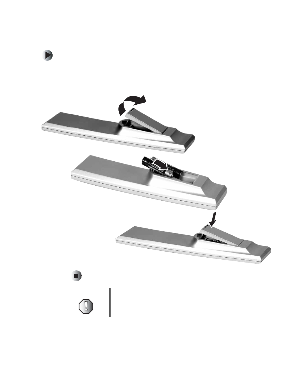
Inserting batteries
To install the batteries:
■ Insert two AAA batteries into the remote control. Ma ke sure that you match
the + and – on the batteries with the + and – symbols inside the battery
compartment.
Universal remote co ntrol
Warning Do not use rechargeable Ni-Cd batteries in this remote
control.
www.gateway.com
11
Page 18

Chapter 1: Checking Out Yo ur Gateway Receiver
12
www.gateway.com
Page 19

Connecting
Components and
Speakers
Read this chapter to learn how to connect your receiver to
audio/video (A/V) component s and speakers.
Important Do not plug the pow er cord in to a w all outlet
or turn the receiver on until all connections
have been made.
2
13
Page 20
Chapter 2: Connecting Com ponents and Speakers
Understanding video connections
Your receiver has two types of standard video connections. You should use the
best connection available to get the best display. For example, if your VCR
supports an S-video connection, connect the VCR to your receiver using S-v ideo
instead of composite video.
Connection
Quality
Good Composite. The video signal is carried
Better S-Video. The video signal is split into two
Cable and Connector Description
through a single “pin.” This connection
method is the one that is most c om m onl y
found on devices.
signals, black-and-white and color. Text
displayed on-scr een throug h this
connection will be noticeably sharper then
composite.
14
www.gateway.com
Page 21
Understanding audio c onnections
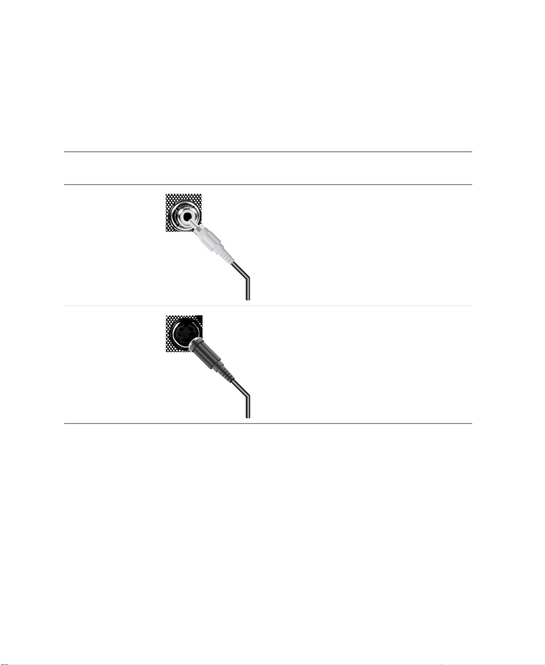
Understanding audio connections
Your receiver has three types of standard audio connections. Yo u should use
the best connection available to get the best sound. Fo r exam ple, if your DVD
player supports a digital audio connection, connect the DVD player to your
receiver using digital audio instead of analog stereo a udio.
Connection
Cable and Connector Description
Quality
Good RCA Analog Stereo
The audio signal is carried through two
cables, one for th e right speak er and one for
the left. This connection method is the one
that is most commonly found on devices.
Best Use digital audio for the best sound quality.
Your receiver supports the following digital
audio connections.
Coaxial Digital
Coaxial cables are common ly used wit h
digital audio signals.
AC-3 (Toslink) Digital
-OR-
Toslink is a connector format for fiber optic
digital audio cables. A fiber optic digital
audio cable carries audio data in the f orm of
light impulses instead of electrical signals.
The Toslink connector is a square plug.
www.gateway.com
15
Page 22
Chapter 2: Connecting Com ponents and Speakers
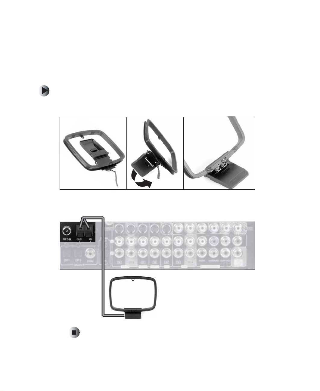
Connecting the AM loop antenna
Place the AM loop antenna as far as possible from the receiver, TV, speaker
cables, and the power cord for best reception. The antenna is directional so set
it to a direction for the best reception.
To connect the AM loop antenna:
1 Unfold the AM loop antenna and snap the loop into the base.
16
2 Connect the antenna leads to the GND and AM clips on your receiver.
www.gateway.com
Page 23

Connecting the FM ante nna
Connecting the FM antenna
Change the position of the FM antenna until you get the best reception of your
favorite FM stations.
To connect the FM antenna:
1 Connect the FM antenna to the FM antenna connector on your receiver.
You may improve FM reception by using an outdoor antenna.
www.gateway.com
17
Page 24
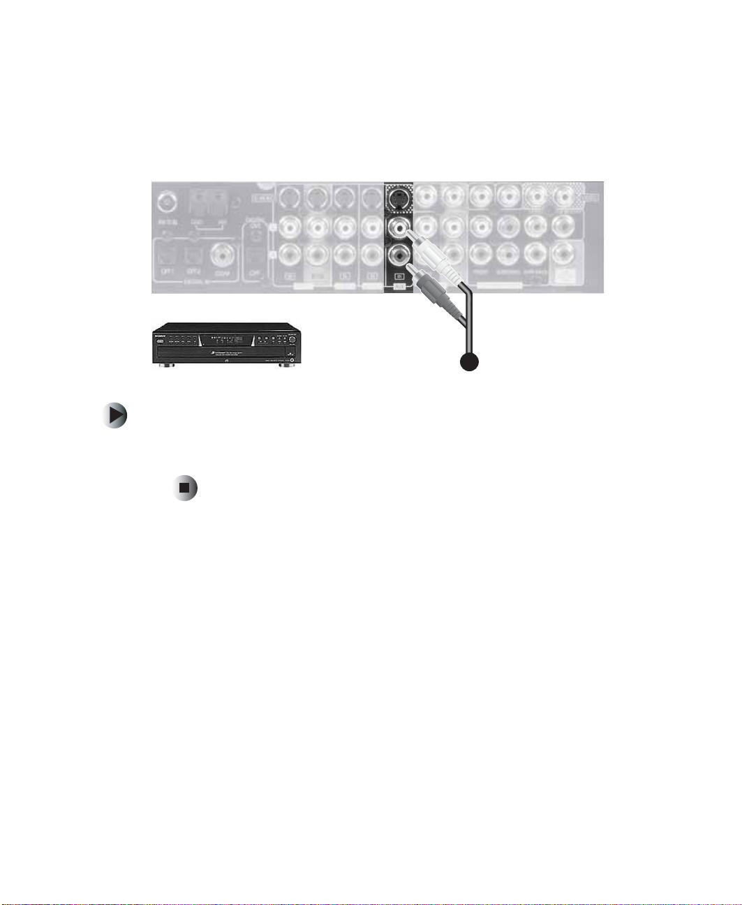
Chapter 2: Connecting Com ponents and Speakers
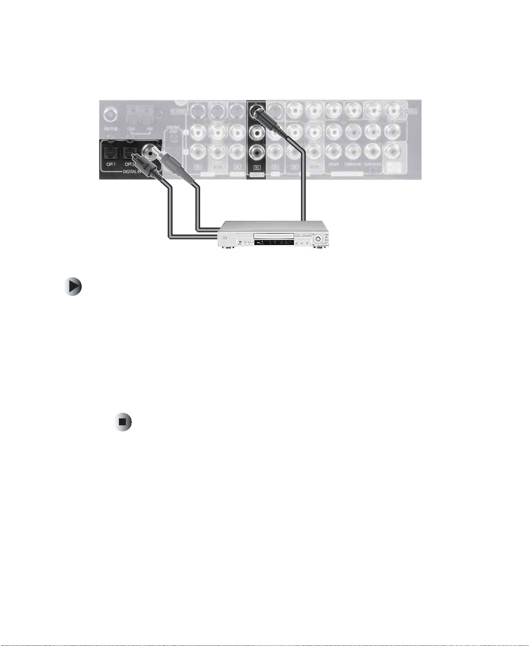
Connecting a D VD player
oror
To connect a DVD player to your receiver:
1 Connect the S-Video jack on the back of your DVD player to the S-Video
jack on your receiver.
18
2 Connect the AC-3 toslink digital audio jack on the back of your DVD player
to the AC-3 toslink digital audio in jack on your receiver.
-ORConnect the coaxial out jack on the back of your DVD player to the coaxial
in jack on your receiver.
www.gateway.com
Page 25
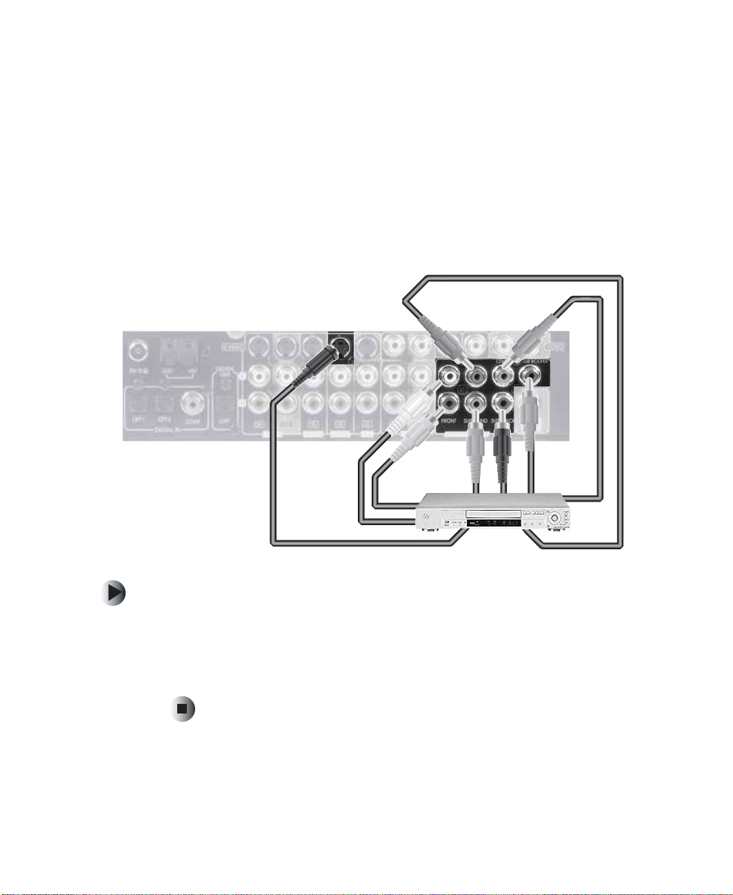
Connecting a 6 or 7 chan nel component
Connecting a 6 or 7 channel
component
Use the 7CH DIRECT INPUT connectors on the receive r to connect the
corresponding a nalog outp uts of a DVD player o r external decoder th at has 6
or 7 channel outputs.
If you are connecting a 6 channel output component, leave the surround back
(SURR BACK) connecto r on the receiver unused.
To connect a 6 or 7 channel component:
1 Connect the analog outputs of your 6 or 7 channel component to the
corresponding 7 ch annel direct input jack s on your receiver.
2 Connect the S-video jack of your 6 or 7 channel compo nent to the S-video
jack on your receiver.
www.gateway.com
19
Page 26
Chapter 2: Connecting Com ponents and Speakers
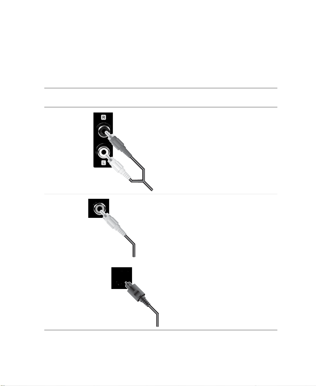
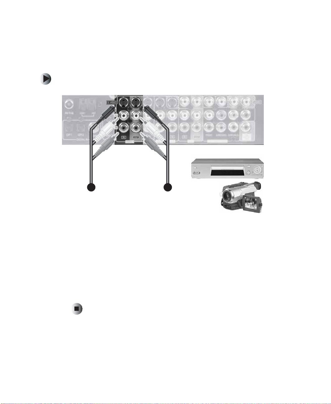
Connecting a VCR
This receiver supports S-Video and composite video ja cks.
To connect a VCR using S-Video:
•
20
1 Connect the red (R) and white (L) audio out jacks on the back of your VCR
to the R and L audio in jacks on your receiver.
2 Connect the red (R) and white (L) au dio in jacks on the back of your VCR
to the R and L audio out jacks on your receiver.
3 Connect the S-video out jack on the back of your VCR to the S-video in
jack on your receiver.
4 Connect the S-video in jack on the back of your VCR to the S-vide o out
jack on your receiver.
www.gateway.com
Page 27
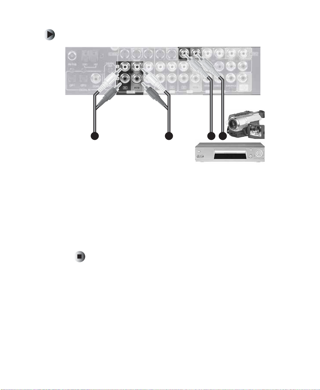
To connect a VCR using composite video:
•
1 Connect the red (R) and white (L) audio out jacks on the back of your VCR
to the R and L audio in jacks on your receiver.
Connecting a VC R
2 Connect the red (R) and white (L) au dio in jacks on the back of your VCR
to the R and L audio out jacks on your receiver.
3 Connect the composite video out jack on the back of your VCR to the
composite video in jack on your receiver.
4 Connect the composite video in jack on the back of your VCR to the
composite video out jack on your rec eiver.
www.gateway.com
21
Page 28
Chapter 2: Connecting Com ponents and Speakers
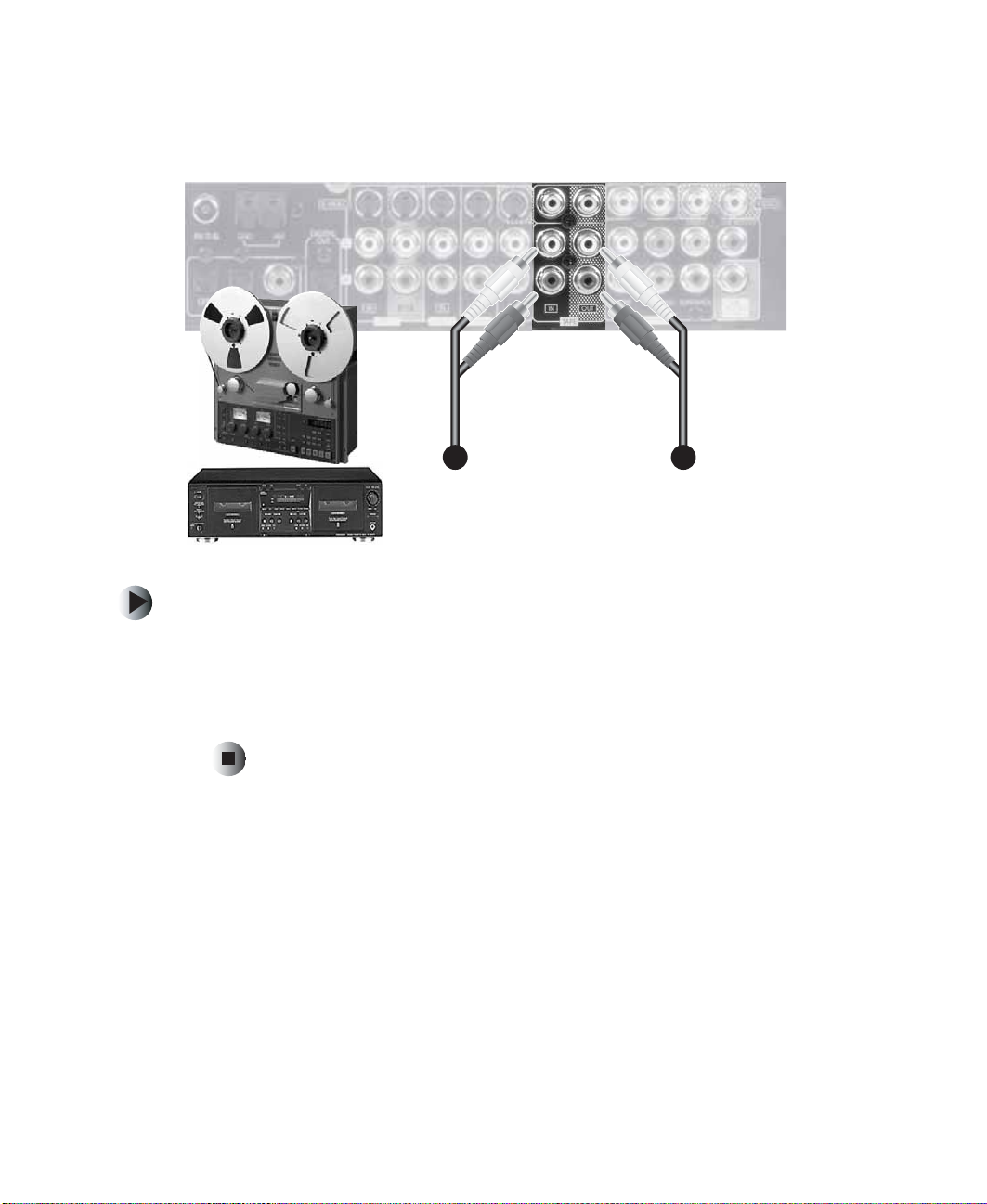
Connecting a tape component
To connect a tape c omponent:
1 Connect the red (R) and white (L) audio out jacks on the back of your tape
component to the R and L audio in jacks on your receiver.
2 Connect the red (R) and white (L) audio in jacks on the back of your tape
component to the R and L audio out jacks on your receiver.
22
www.gateway.com
Page 29
Connecting an AUX co mponent
Connecting an A UX component
The AUX jacks may be connected to an additional audio component such as
a CD player, tape deck, or game conso le.
To connect an AUX component:
1 Connect the red (R) and white (L) audio out jacks on the back of your AUX
component to the R and L audio in jacks on your receiver.
www.gateway.com
23
Page 30
Chapter 2: Connecting Com ponents and Speakers
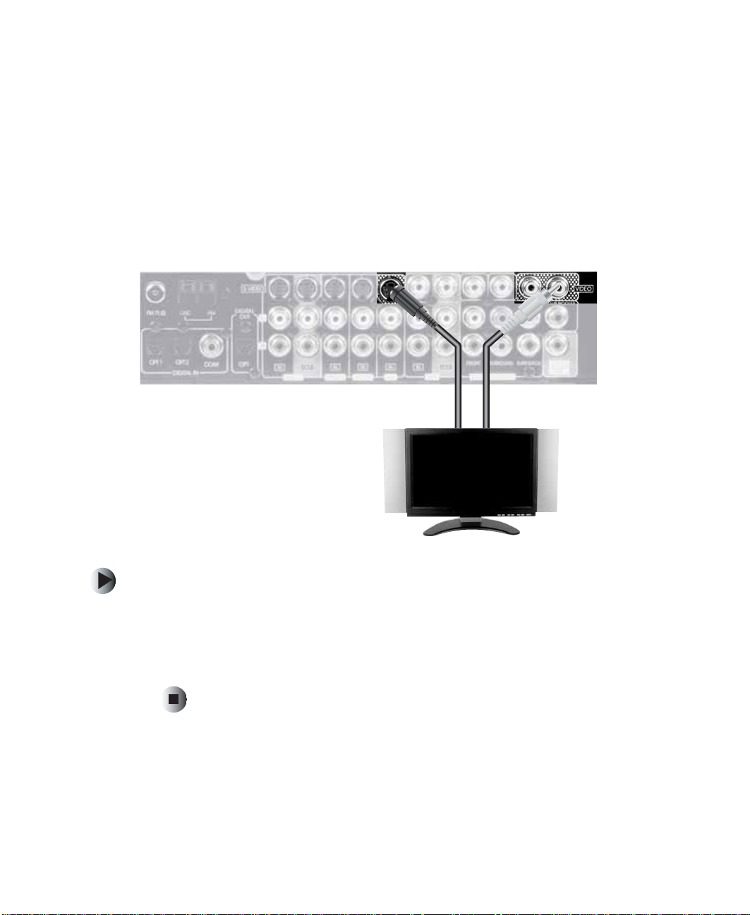
Connecting a television
This receiver supports S-Video and composit e video jacks. As you are making
your television (monitor) connections an d using your receiver, keep in mind
that a signal input into the c omposite VIDEO IN jack is output to the compo site
VIDEO OUT jacks and a signal input into the S-VIDEO IN jack is output to the
S-VIDEO OUT jacks and the composite MONITOR 1 and MONITOR 2 VIDEO
OUT jacks. For this reason, we recommend connecting your receiver to your
TV using both S-Video and composite video. (S-Video cable not supplied)
To connect your receiver to a television:
1 Connect the Monitor S-Video out jack on the back of your receiver to the
S-Video in jack on your television.
2 Connect the Monitor 1 or Monitor 2 composite video out jac k on the back
of your receiver to the composite video in jac k on your television.
24
www.gateway.com
Page 31

Connecting speakers
Connecting speakers
Speaker placement
Ideal speaker placement varies depending on the size of your ro om, wall
coverings, and other environment variables. The following information depicts
typical placement recommendations.
Front left and right speaker s and center speaker
■ Place the front speakers so they are no closer to the listening area than
the center speaker.
■ Place the center speaker between the front left an d right spea kers and no
further from the listening area than the front speakers. Generally, center
speaker placement is made either directly above or directly below the TV.
■ Place each speaker so that sound is aimed at your ears while you are seated
in your main listening area.
www.gateway.com
25
Page 32

Chapter 2: Connecting Com ponents and Speakers
Surround left and right speaker s
■ Place the surround speakers approximately 40 inches (1 meter) above the
ear level of a seated listener on the direct left and right or slightly behind
the listener.
Surround back speaker
■ Place the surround back speaker at the rear center of your listening area
facing toward the listening area at a slightly higher position
(0 to 10 inches) than the surround speakers.
■ We recommend installing the surround back speaker at a slightly
downward facing angle. This helps prevent the surround back channel
signals from reflecting off the TV or screen at the front center.
Subwoofer
■ The powerful deep bass sounds produced by the subwoofer are
non-directional, meaning you cannot tell where the sound is coming from.
Place the subwoofer anywhere in your room. The closer to a wall or corner
that you place your subwoofer the bassier the sound becomes.
Making the connections
Connect speakers firmly and correctly according to their channel (left and right)
and their polarity (+ and –). If the connections are faulty, the speakers will not
reproduce sound. If the polarity of the connections are incorrect, the sound
will be unnatural and lack bass.
Warning Use speakers with an impedance of 6 ohms or above.
Do not let the bare speak e r w ires tou ch eac h oth er or a n y
metal part of this receiver. This could damage the receiv er
and/or the speakers.
26
www.gateway.com
Page 33

Connecting speakers
To connect speakers to your receiver:
1 Connect the striped-edge speaker cable to the red (positive) speaker cable
connector. Connect the non-striped edge speaker cable to the black
(negative) speaker cable connector.
Important Make sure that you clamp down on the bare speaker wire
and not on the insulation.
www.gateway.com
27
Page 34

Chapter 2: Connecting Com ponents and Speakers
2 Connect the right and left surround speakers and the back surround
speaker to the receiver. Match the positiv e and negative cables from Step 1
to the positive and negative connectors on the receiver.
28
www.gateway.com
Page 35

Connecting speakers
3 Connect the center speaker to the receiver, making sure to match the
positive and negative connectors.
www.gateway.com
29
Page 36

Chapter 2: Connecting Com ponents and Speakers
4 Connect the left and right front speakers to the center speaker, making
sure to match the positive and negative connectors.
30
www.gateway.com
Page 37

5 Turn the center speaker’s Ventriloquist Function to ON.
Connecting speakers
www.gateway.com
31
Page 38

Chapter 2: Connecting Com ponents and Speakers
6 Connect the subwoofer to the receiver.
32
www.gateway.com
Page 39

7 Plug in the subwoofer.
Connecting speakers
www.gateway.com
33
Page 40

Chapter 2: Connecting Com ponents and Speakers
8 Switch the su bwoofer to Digital Receiver, turn the Volume to ~5, then flip
the
POWER switch to ON.
34
Certain settings need to be made to your receiver to match your KAS-303
speakers. See “Setting up your speakers” on page 39 for more information
on setting up and configuring your speakers.
www.gateway.com
Page 41

Plugging in your comp onents
Plugging in y our components
After you have made all the connections, plug in your receiver and your
connected componen ts.
www.gateway.com
35
Page 42

Chapter 2: Connecting Com ponents and Speakers
36
www.gateway.com
Page 43

Using the
Receiver
Read this chapter to learn how to:
■ Turn the receiver on and off
■ Set up the speakers
■ Use the universal remote control
■ Listen to a program source
■ Understand surround sound
■ Listen to the radio
■ Record analog audio and vide o
■ Record digital aud io
■ Use the sleep timer
■ Adjust the display brightness
3
37
Page 44

Chapter 3: Using the Re ceiver
Tu rning the receiver on and off
To turn the receiver on:
1 Press the power button on the receiver. The receiver enters Standby mode.
Each subsequent press of the power button on the receiver switches the
receiver between Standby mode and o ff.
2 Press the power button on the remote control. The receiver turns on.
Each subsequent press of the power button on the remote control switches
the receiver between Standby mode an d on.
To turn the receiv er off:
■ Press the power button on the receiver. The receiver turns off.
POWER
38
www.gateway.com
Page 45

Setting up your sp eakers
Setting up your speaker s
Adjusting the speaker settings
After you have installed your receiver and connected all the components, you
should adjust the speaker settings for the optimum sound acoustics for your
environment and speaker layout.
Setting the type of speake rs
The composition and frequency response of the signals from the sur round
channels adjust automatically according to the combination of speaker types
in use.
Select
Large or Small not according to the actual size of the speaker but according
to the speaker’s capacity for playing low frequency signals.
Crossover Frequency is the frequency (Hz) below which the bass sound of each
main speakers is instead sent to the subwoofer or, when not using a subwoofer,
speakers set to
Large — Select this when connecting speakers that can fully reproduce sounds
below the Crossover Frequency of your speakers.
Large.
Small — Select this when connecting speakers that cannot fully reproduce
sound below the Crossover Frequency. When this setting is selected, sound
below the Crossover Frequency is assigned to the subwoofer or , when not using
a subwoofer, speakers set to
None — Select this when no surround speakers are connected. When this
setting is selected, the surround sound signals are sent to the front speakers.
Large.
www.gateway.com
39
Page 46

Chapter 3: Using the Re ceiver
Yes / None — Select Yes if a subwoofer is connected. Select None if a subwoofer
is not connected.
■ See the specifications of the speakers that you are connecting. For example,
if the frequency range of your speakers is 80 Hz ~ 12 KHz, then the
Crossover Frequency is 80 Hz.
■ If you do not know the specifications for your speakers, try comparing the
sound at both settings (set the volume to a low level so you do not damage
the speakers) to determine the correct setting.
■ Depending on how you set your speakers, not all options ma y be availab le
to you. For example, if you set your Front L/R speakers to
have
Large, Small, and None as options for your Center speaker. But if you
set your Front L/R speakers to
Center speaker will be
Large, you will
Small, the only options available for your
Small and None.
40
www.gateway.com
Page 47

Setting up your sp eakers
T
Speaker distance settings
When using 5.1 channel surround playback with Dolby Digital o r DTS sour ces,
the center and surround speakers should be the same distance from the main
listening position as the front speakers. By specifying the distance between the
listening position and each speaker, the center and surround speaker’s delay
times automatically adjust to create the ideal listening environment.
To adjust the speaker settings:
SPK SE
1 Press the Speaker Setup button on the remote control to cycle
between the available Speaker Setting Modes.
2 When the Speaker Setting Mode you want to adjust is selected, press the
-ADJUST-
Adjust Up or Adjust Down buttons on the remote control to
change the speaker setting.
Displayed symbol Correspond ing setting
F Front
CCenter
S Surround
LLarge
SSmall
NNone
■ When adjusting the Crossover Frequency setting for your subwoofer, the
available options are 80 Hz, 120 Hz, 160 Hz, and 200 Hz. Your KAS-303
Home Theater satellite speakers have a range of 150 Hz ~ 18.5 KHz, so set
the subwoofer Crossover Frequency to 160 Hz.
You can also adjust speaker settings using your remote control and the OSD.
For more information, see “OS D menus and options” on page 6 6.
You can also adjust speaker settings using the SETUP button on the receiver
www.gateway.com
41
Page 48

Chapter 3: Using the Re ceiver
Using the universal remote control
Operating components with the universal remote control
To operate components with the universal remote control:
1 Enter the Setup code for each component, other than this receiver, that
you want to control. For more information, see “Programming the remote
control” on pag e 43.
2 Turn on the component you want to operate.
3 Press the DEVICE button on the remote control that corresponds to the
component you want to operate.
42
www.gateway.com
Page 49

Using the universal remote control
4 Aim the remote control at the remote sensor of the component that you
want to operate and press the button that corresponds to the function yo u
want to perform.
o
60
7m
Programming the remote control
This remote control can control up to 8 different components.
Before operating audio and video components, other than this receiver, use this
remote control to enter the setup code for each compon ent.
By factory default, 000 is stored in the memory for the CD, DVD, and AUX
device buttons. You do not need to enter a code unless the default code of 000
does not work.
www.gateway.com
43
Page 50

Chapter 3: Using the Re ceiver
Entering a setup code
To enter a setup code:
1 Turn on the component you want to control.
2 Locate the setup code for your connected component. See “Setup Codes”
on page 80.
3 While pressing and holding down the ENTER button on the remote
control, press the DEVICE button on the remote control for the
corresponding component for more than 1 second. The LED flickers once.
The AUDIO DEVICE button is reserved for the receiver and cannot be
programmed for other components.
4 While aiming the remote control at the remote sensor on your connected
component, enter the 3-digit code that you located in Step 2.
If you entered the code correctly, the LED flickers twice. Test the code by
pressing the POWER (or STANDBY) button on the remote control. If your
component does not turn off, repeat the procedure using each code listed
for your component’s manufacturer until you find a code that works.
If the LED did not flicker twice, repeat the above procedure and tr y entering
the same code again .
Manufacturers may use different setup codes for the same product category.
Check to see if the code you have entered operates as many controls as possible.
If only a few functions operate, check to see if another co de operates more
buttons.
Programming a macro function
Using the macro function, you can program up to 10 remote control button
presses into a single button. The universal remote control h as 3 macro buttons,
M1, M2, and M3.
44
www.gateway.com
Page 51

Using the universal remote control
To program a macro:
1 Press and hold down both the ENTER button on the remote control and
the macro button you want to program ( M1, M2, or M3). The L ED flickers
once.
2 First press the DEVICE button for the device that you want to control with
this macro, then press the operation buttons you want to program in the
order that you want them to execute.
3 Press the ENTER b utton on t he remot e contro l. If the m acro was
programmed successfully, the LED flickers twice.
Remove a macro by following the above pro cedure except skip Step 2.
Change a macro by progra mming a new macro into the macro button. The new
macro automatically overwrites the old macro.
Using a macro function
To use a macro:
■ Aim the remote control at the remote control sensor of the component
that you want to operate, then press the macro button for the macro you
want to run.
The macro function of this remote control may not work with all compone nts.
For example, the codes programmed into a MACRO button transmit at
0.5 second intervals. If the comp onent cannot complete an op eration within
0.5 seconds, it may miss the next code. In this example, you would not be able
to use that particular macro with the component.
www.gateway.com
45
Page 52

Chapter 3: Using the Re ceiver
Switching between connected components
To switch between connected components:
1 Press the Input Selector button on the receiver or press one of the Direct
Input Selector
■ The available input source changes are: Tuner, Tape, Aux, Video 1,
Video 2, Video 3, an d 7-Direct.
2 If you selected Aux, Video 1, Video 2, or Video 3, press the Digital Input
button on the receiver to selec t th e corresp onding dig ital o r ana log inpu t.
■ The available digital or analog inputs are: A(nalog), o(ptical) 1,
o(ptical) 2, and c(oa xial) 1
3 Press the Decoding button on the receiver or the Auto button on the remote
control to select the decoding mode you want.
■ The available decoding modes are: In-Auto, In-DTS, and In-PCM.
buttons on the remote control.
46
■ You cannot select a decoding mode unless you have also selected a
digital input source.
■ Noise may be generated at the beginning of playback and while
searching when you are i n
playback. If this ha ppens, switch to
In-Auto decoding mode during DTS
In-DTS mode.
4 Use the component you selected for playback.
5 Press the up and down Volume buttons on the receiver or on the remote
control to adjust the volume.
www.gateway.com
Page 53

6 If you want to mute the sound, press the MUTE button on the remote
control.
7 If you want to listen with headphones, connect headphones to the Phones
jack on the receiver. Sound to the speakers is automatically turned off and
any multi-channel sound is automatically downmixed to a 2-channel
(
2-CH DOWNMIX) downmix mode.
You can also select the digital signal input using your remote control and the
OSD. For more information, see “Using the OSD” on page 63.
Surround sound
This receiver incorporates a sophisticated Digital Signal Processor that lets you
create optimum sound quality and sound atmosphere in your personal Home
Theater.
Surround modes
Surround sound
Your receiver supports multichannel surround modes and 2-channel surround
modes.
Multichannel surround modes
Mode Description
DTS™ Digital
Surround
DTS - ES Extended
Surround
DTS Neo: 6
surround
™
™
DTS Digital Surround (DTS) is a multichannel digital signal format which
handles higher data rates than Dolby Digital.
This is a new multichannel digital signal format which greatly improves the
360-degree surround impression and space expression. In addition to the
5.1 channels, DTS-ES Extended Surround also offers the surround back
(sometimes also referred to as surround center) channel for surround
playbac k w ith a to tal of 6.1 ch ann els. DTS-ES Extended Surround includes
the DTS-ES™ Discrete 6.1 and DTS-ES™ Matrix 6.1 signal formats.
This mode applies conventional two-channel signals such as digital PCM
or analog stereo signals to the high precision digital matrix decoder used
for DTS-ES Ma trix 6 .1 to achiev e 6 .1-c han nel s urro und p layback. DTS Neo
: 6 includes DTS Neo: 6 Cinema and DTS Neo: 6 Music signal formats.
www.gateway.com
47
Page 54

Chapter 3: Using the Re ceiver
Mode Description
Dolby Digital
Dolby Digital EX
Dolby Pro Logic
Dolby Pro Logic II
surround
MPEG
Multichannel
™
Dolby Digi tal discs support recording s of up to 5.1 chan nels of digital si gnals,
which reproduce m uch better s ound quality, spatial e xpansion, an d dynamic
range characteristics than the previous Dolby Surround effects.
™
This mode uses a matrix decoder to create the back (sometimes referred
to as surround center) signal from the surround left and right signals in a
Dolby Digital 5.1 channel source and provides 6.1 channel surround
playbac k. For th e best results , this mode s hould be select ed during pla yback
of sources reco rded in Dolby Di gital Surrou nd EX.
When Dolby Digital EX sources are decoded with a Dolby Digital EX
decoder, the format is automatically detected and Dolby Digital EX mode
is selected. However, some Dolby Digital EX sources may be detected as
Dolby Digital sources. In this case, the Dolby Digital EX mode should be
selected manually.
™
Dolby Pro Logic is a specially encoded two-channel surround format which
consists of four channels (front left, center, front right, and surround). The
surround channel is monaural and is played through both surround
speakers.
™
This mode applies conventional two-channel signals such as digital PCM
or analog stereo signals as well as Dolby Surround signals to surround
processing. Dol by Pro Lo gic II surrou nd include s Dolby Pro Logic II Cinema,
Dolby Pro Logic II Music, and Dolby Virtual signal formats.
™
Though the number of audio channels is 5.1 (which is the same as Dolby
Digital), MPEG Multichannel
sounds to the correct posit ion in the sound stage . MPEG Multichannel works
well when using the 7 CH DIRECT INPUTs to playback the sound from an
additional multi channel d ecoder . F or details , see to the user’ s guide f or y our
connected 7-channel component.
discs are much better at matching individual
48
www.gateway.com
Page 55

Surround sound
2-channel surround modes
The following modes apply conventional 2-channel signals such as digital PCM
or analog stereo signals to high performance Digital Signal Processor to recreate
sound fields artificially. Select from one of th e following 2-channel surround
modes:
Mode Description
Theater This mode provides the effec t of being in a theater -in-the round while w atching a pla y .
Movie This mode provides the effect of being in a movie theater while watching a movie.
Hall 1/2 This mode provides the ambience of a chamber hall for chamber music or an
instrumental solo (Hall 1) or a concert hall for orchestral music or an opera (Hall 2).
Stadium This mode provides the expansive sound field to achieve the true stadium effect of
watching sporting events, such as football.
Church This mode provide s the ambience of a church f or baroque, st ring orchestral, or cho ral
group music.
Club 1/2 This mode creates the sound field of a jazz club with a low ceiling and hard walls
(Club 1) or a live club with a relatively spacious floor (Club 2).
Arena 1/2 This mode provides the f eeling o f a liv e conce rt in a medium-siz ed (Arena 1) o r large
(Arena 2) arena.
Game Use this mod e for video game sources.
Matrix This mode reproduc es d ela y ed sign als fro m the surrou nd cha nnels emph asiz ing the
sense of expansion for music sources.
www.gateway.com
49
Page 56

Chapter 3: Using the Re ceiver
For your reference, the sound from each channel can be reproduced according
to the surround modes as follows:
Modes Channels
Front
L/R
DTS × × × ×
DTS ES DISCRETE/MATRIX × × × × ×
DTS NEO CINEMA/MUSIC × × × × ×
DOLBY DIGITAL × × × ×
DOLBY DIGITAL EX × × × × ×
DOLBY PRO LOGIC × × × ×
DOLBY PRO LOGIC II CINEMA/MUSIC × × × ×
DOLBY VIRTUAL × ×
MPEG × × × ×
MATRIX × × × ×
Other Surround × × × ×
STEREO × ×
7 CH DIRECT × × × × ×
Center Surround
L/R
Surround
Back
Subwoofer
Selecting the surround mode
To select the surround mode:
■ Press the left and right DSP mode buttons on the remote control to cycle
through the surround modes.
50
www.gateway.com
Page 57

Surround sound
The signal format of your selected input source determines the available
surround modes.
Signal format of input source Selected decoding mode Selectable surround mode *
Dolby Digital 5.1,
Dolby Digital EX 6.1 channel sources
Dolby Digital 2-channel IN-AUTO mode (DOLBY DIGITAL EX),
PCM (2 channel) sources IN-AUTO, IN-PCM mode PL II CINEMA, PL II MUSIC,
Analog ster eo sourc es
DTS sources IN-AUTO, IN-DTS mode corresponding DTS mode
MPEG sources IN-AUTO mode corresponding MPEG mode
IN-AUTO mode (DOLBY DIGITAL EX),
DOLBY DIGITAL,
DOLBY VIRTUAL
PL II CINEMA, PL II MUSIC,
PRO LOGIC, DOLBY VIRTU AL
PRO LOGIC,
DOLBY VIRTUAL,
NEO 6 CINEMA,
NEO 6 MUSIC, THEATER,
MOVIE, HALL 1/2, STADIUM,
CHURCH, CLUB 1/2,
ARENA 1/2, GAME, MATRIX
* Items in parenthesis are only selectable when the surround back speaker
setting is not
■ When 96 kHz PCM signals are input, stereo mode is selected automatically
N.
and surround mode cannot be selected.
■ When DTS or MPEG signals are input in the IN-AUTO or IN-DTS mode,
the corresponding DTS or MPEG modes are selected reg ardless of DSP
MODE button actions.
■ When the selected decoding mode is not matched to the input signal
format, the DIGITAL indicator flickers and no sound is heard. Be sure to
select the required decoding mode and the available surround mode
according to the input signal format.
■ When the 7 CH DIRECT is selected as an input source, the decoding an d
surround modes cannot be selected.
■ When the selected input signals are not digital signa ls, the surround mode
cannot be selec ted.
■ When using headphones, the surround mode cannot be selected.
www.gateway.com
51
Page 58

Chapter 3: Using the Re ceiver
To select stereo mode:
■ Press the Stereo button on the remote control to cancel surround mode
and switch to stereo mode.
If Stereo mode is applied to a multi-channel DTS, Dolby Digital, or MPEG signal,
the signal is downmixed to a 2-channel downmix (
allowing the multi-channel signal to be reproduced through only two speakers
or through headphones.
2-CH DOWNMIX) mode,
To cancel Stereo mode a nd switch back to surroun d mode, use the
buttons on your remote control.
Adjusting the channel levels
You can adjust your channel levels using test tones or manually. Ideally you
should use the test tone method first and then make any additional adjust ments
through the manual process.
To adjust channel levels using test tones:
1 Press the T. T one button on the remote control. The test tone plays out of
each channel in a 2-second cycle. If a speaker setting is
will not play out of that channel.
2 Press the CH/LEVEL up and down buttons on the remote control to adjust
the level for each channel .
3 Press the T. To n e button on the remote control to cancel the test tone.
N, the test tone
DSP Mode
52
www.gateway.com
Page 59

To adjust channel levels manually:
1 Press the Ch. SEL button on the remote control. Each time the button is
pressed, the corresponding channel is selected a nd displayed for several
seconds.
■ If the receiver is set to Stereo or Dolby Virtual mode or if the speaker
setting is set to
subwoofer channel cannot be selected.
■ If the headphones are connected, you can only select the front L/R
channel.
N, center, surround L/R, surround back, or the
2 Press the CH/LEVEL up and down buttons on the remote control to adjust
the level of the selected channel.
3 Repeat Step 1 and Step 2 to adjust ea ch channel level.
Storing channel le vels in memory
You can store channel level settings in memory. This lets you change the
channel levels, then recall the stored settings.
Surround sound
To store c hannel levels in memory:
1 Press the SETUP button on the receiver for more than 2 seconds to enter
Setup mode.
2 While in Setup mode, repeatedly press the SETUP button on the receiver
until
P CALL appears.
3 While displaying P CALL, press the ADJUST up and down buttons on the
receiver to select
P MEMORY.
4 Press the DECODING button on the receiver to confirm.
www.gateway.com
53
Page 60

Chapter 3: Using the Re ceiver
To recall channel levels from memory:
1 Press the SETUP button on the receiver for more than 2 seconds to enter
Setup mode.
2 While in Setup mode, repeatedly press the SETUP button on the re ceiver
until
P CALL displays.
3 While displaying P CALL, press the ADJUST up and down buttons on the
receiver to select
P CALL.
4 Press the DECODING button on the receiver to confirm.
You can also work with channel levels using your remote control and the OSD.
For more information, see “OS D menus and options” on page 6 6.
Adjusting the LFE level
Y ou c an adjust the Low Frequency Effect (LFE) lev els in Dolby Digital, DTS, and
MPEG program sources.
To adjust the LFE level:
1 Press the SETUP button on the receiver for more than 2 seconds to enter
Setup mode.
2 While in Setup mode, repeatedly press the SETUP button on the re ceiver
until
DD L displays.
3 While displaying DD L, press the DECODING button on the receiver to cycle
between the available modes: Dolby Digital LFE (
and MPEG LFE (
MP L).
DD L), DTS LFE (DTS L),
4 While displaying the LFE mode you want, press the ADJUST up and down
buttons on the receiver to adjust the level.
You can also adjust the LFE level using your remote control and the OSD. For
more information, see “OSD menus and options” on page 66.
54
www.gateway.com
Page 61

Adjusting the tone
You can adjust the tone (bass and treble).
To adjust tone:
1 Press the SETUP button on the receiver for more than 2 seconds to enter
Setup mode.
2 While in Setup mode, repeatedly press the SETUP button on the receiver
until
TONE OF F or BASS appears.
3 While displaying BASS, press the DECODING button on the receiver to cycle
between the available modes:
4 While displaying the tone mode you want, press the ADJUST up and down
buttons on the receiver to adjust the tone.
You can also adjust the tone settings using your remote control and the OSD.
For more information, see “OS D menus and options” on page 6 6.
BASS, TRBL, and TON E ON .
Surround sound
Compressing the dynamic range
You can adjust the compression of Dolby Digital program sources to minimize
the volum e diff ere nce be tween hig h and lo w levels. This feature is useful if you
are listening to Dolby Digital program sour ces at low volume levels. This fea ture
can only be used for Dolby Digital program sources.
To compress the dynamic range of Dolby Digital program sources:
1 Press the SETUP button on the receiver for more than 2 seconds to enter
Setup mode.
2 While in Setup mode, repeatedly press the SETUP button on the receiver
until
DYNR 0.0 appears.
www.gateway.com
55
Page 62

Chapter 3: Using the Re ceiver
3 While displaying DYNR 0.0, press the ADJUST up and down buttons on the
receiver to cycle between the available modes:
Compression
, and DYNR 1.0: High Compression.
D YNR 0.0: Off, DYNR 0.5: Low
4 While displaying the tone mode you want, press the ADJUST up and down
buttons on the receiver to adjust the tone.
This function may not be available in some Dolby Digital program sources.
You can also adjust the dynamic range compression levels using your remote
control and the OSD. For more information, see “OSD menus and options” on
page 66.
Adjusting Dolby Pro Logic II Music parameters
You can adjust the surround parameters of Dolby Pro Logic II Music mode.
To adjust Dolby Pro Logic II Music parameters:
1 Press the PL II PARA. button on the remote control to select from the
following parameters:
56
■ Panorama mode (PANO) – Extends the front stereo image to include
the surround speakers to give a wraparound effect with side wall
imaging.
Range: OFF or ON (default is OFF)
■ Center width control (C-WID) – Adjusts the center image so it is heard
from only the center channel speaker, only from the left/right speakers
as a phantom image, o r from all three front speaker s.
Range: 0 to 7 (default is 0)
■ Dimension control (DIMEN) – Ad justs the sound field towards the front
or towards the rear.
Range: -4 to +2 (default is 0)
2 While displaying the parameter you want, press the ADJUST buttons on
the remote control to change the values.
www.gateway.com
Page 63

Listening to the radio
Listening to the radio
Selecting the tuner
To select the tuner:
1 Press the INPUT SELECTOR button on the receiver or the TUNER button on
the remote control to select the tuner.
2 Press the AM/FM MODE button on the receiver to cycle between the
following bands:
When FM stereo broadcasts are poo r because of weak broadcast signals, select
the FM mono mode to reduce the noise. The FM broadcasts are reduced to
monaural sound.
Manual tuning
FM STEREO, FM MONO, and AM.
To manually tune the tuner:
1 If you are using the buttons on the receiver, repeatedly press the TUNE
MODE
button on the receiver to select Tuning mod e. The PRESET light turns
off.
- OR If you are using your remote control, go to the next step.
2 Repeatedly press the up and down TUNING/PRESET buttons on the rec eive r
or the – and +
want is set.
TUNE buttons on the remote control until the frequency you
www.gateway.com
57
Page 64

Chapter 3: Using the Re ceiver
Auto tuning
To automatically tune the tuner:
1 If you are using the buttons on the receiver, repeatedly press the TUNE
MODE
button on the receiver to select Tuning mod e. The PRESET light turns
off.
- OR If you are using your remote control, go to the next step.
2 Press the up and down TUNING/PRESET buttons on the receiver or the
–and+
The tuner searches until a station of sufficient strength is found.
Weak stations are skip ped during auto tu ning. To tune in a weak station, use
manual tuning.
TUNE buttons on the remote control for more than 0.5 seconds.
Memorizing radio stations
You can store up to 30 radio stations in memory.
To memorize radio stations:
1 Tune in a station using manual or auto tuning.
2 Press the MEMORY button on the receiver. The MEM light flickers for
5 seconds.
3 Press the up and down TUNING/PRESET buttons on the receiver or the
–and+
number (1~30) you want, then press the
You can erase a stored frequency by storing another frequency in its place.
58
PRESET buttons on the remote control to select the desired preset
MEMORY button on the receiver.
www.gateway.com
Page 65

T uning to preset stations
To tune to preset stations:
1 If you are using the buttons on the receiver, repeatedly press the TUNE
MODE
button on the receiver to select Preset mode. The PRESET light turns
on.
- OR If you are using your remote control, go to the next step.
2 Press the up and down TUNING/PRESET buttons on the receiver or the
–and+
number (1~30).
PRESET buttons on the remote control to select the desired preset
Analog Audio/ Video reco rding
You can scan all of the preset stations in sequence by pressing the
button on your remote control. The receiver pauses at each preset station for
5 seconds. When the station you want is tuned, press the button again to stop
scanning.
Analog A udio/Video recording
■ The analog signals (except front L/R channel) from the 7 CH DIRECT
inputs and the digital signals from the coaxial or optical digital inputs
cannot be recorded.
■ The volume and tone (bass and treble) settings have no effect on the
recording signals.
To record with TAPE:
1 Press the INPUT SELECTOR button on the receiver or the direct input
selector button on the remote control to select the i nput for your recording
source. You cannot select
2 Start recording on the con nected TAPE component.
3 Start playing on the selected input (recording source).
TAPE.
P. SCAN
www.gateway.com
59
Page 66

Chapter 3: Using the Re ceiver
To dub from video components onto VIDEO 1:
1 Press the INPUT SELECTOR button on the receiver or the VIDEO2 or VIDEO3
direct input selector button on the remote control to select
VIDEO3 as your recording source.
2 Start recording on the con nected VIDEO 1 componen t.
3 Start playing on the VIDEO 2 or VIDEO 3 selected input (recording source).
To dub separate audio and video source signals onto VIDEO 1:
1 Press the INPUT SELECTOR button on the receiver or the AUX direct input
selector button on the remote control to select
source. Make sure your audio recording source, such as a CD player, is
connected to the
2 Press the OSD button on the remote control and select FUNCTION SELECT,
VIDEO SELECT, then select VIDEO 2.
3 Start recording on the con nected VIDEO 1 componen t.
VIDEO2 or
AUX as your audio recording
AUX jacks.
60
4 Start playing on the AUX and the VIDEO 2 inputs (recording source).
www.gateway.com
Page 67

Digital Audio recordi ng with an MD recorder
Digital A udio recording with an MD
recorder
■ You can only record digitally (without digital to analog conversion) when
the OPTICAL DIGITAL OUT jack of this receiver is connected to the
OPTICAL DIGITAL IN jack of an MD recorder or CD recorder.
■ Digital recording is available for the digital audio program sources such as
CDs, MDs, and some DVDs.
■ In most DVDs, as well as some CDs, digital rec ording may not be a vailable
(depending on the signal format).
■ There are some restrictions on recording digital signals. See the operating
instructions of your digital recording equipment to see which restrictions
apply to you.
. To record digital audio with an MD recorder:
1 Press the INPUT SELECTOR button on the receiver or the AUX, VIDEO1,
VIDEO2, or VIDEO3 direct input selector button on the remote control to
select
AUX, VIDEO1, VIDEO2, or VIDEO3 as the input for your recording
source.
2 Press the DIGITAL INPUT button on the receiver to select the o(ptical) 1,
o(ptical) 2, or c(oaxial) 1 as your digital si gnal input.
3 Start recording on the component connected to OPTICAL DIGITAL OUT.
4 Start playing on the selected digital input (recording source).
You can also select the digital signal input using your remote control and the
OSD. For more information, see “Using the OSD” on page 63.
www.gateway.com
61
Page 68

Chapter 3: Using the Re ceiver
Using the sleep timer
Use the sleep timer to automatically turn the receiver off after a specified period
of time.
. To use the sleep timer:
■ Press the SLEEP button on the remote control to cycle between the
following sleep timer settings:
turns on.
10, 20, 30, 60, 90, and OFF. The SLEEP light
Adjusting the display brightness
You ca n dim or turn off the receiver’s display.
. To adjust the display brightness:
■ Press the DIMMER button on the remote control to cycle between the
following brightness settings:
In the OFF display mode, press any button to restore the display to ON mode.
62
www.gateway.com
ON, dimmer, and OFF.
Page 69

Using the OSD
Read this chapter to learn how to adjust your receiver
settings from the on-screen display (OSD).
4
63
Page 70

Chapter 4: Using the OSD
Displaying the current status
When the AUTO OSD is set to ON the receiver displays status information. The
information displays for several seconds then automatically turns off.
One example of displayed status information is shown below.
Displayed status inf ormation when selecting TEST T ONE mode
64
FL :--------------- ----------------: 0db
www.gateway.com
Page 71

Using the Menu screen
Navigate the Menu screen using the cursor control ( , , , and ),
OSD ( ), and ENTER ( ) buttons on your remote control.
OSD
To adjust settings from the OSD:
1 Press the OSD button on the remote control. The Main Menu opens.
ENTER
MAIN MENU
SPEAKER SETUP
FUNCTION SELECT
SURROUND MODE
SH LEVEL SETUP
AUTO OSD :
ON
Using the Menu screen
OSD : QUIT , : MOVE
ENTER : SELECT OR CHANGE
Press the
OSD button on the remote control again to close the Main Menu.
2 Press the cursor up and down buttons on the remote control to select the
menu item you want.
3 Press Enter on the remote control to confirm your selection.
4 Press the cursor up and down buttons on the remote control to select the
option you want.
5 Follow the on-screen instructions to adjust the option.
www.gateway.com
65
Page 72

Chapter 4: Using the OSD
OSD menus and optio ns
Use these OSD menus and options to adjust various setting for your receiver.
Menu OSD Display Description
Speaker Setup Configure Speaker settings.
SPEAKER SETUP
SUBWOOFER :
FRONT :
CENTER :
SURROUND :
SURR. BACK :
SUBWOOFER : ACTIVE
OSD : BACK , : MOVE
ENTER :CHANGE 1/2 PAGE
UNIT :
FRONT L : 10ft
FRONT R : 10ft
CENTER : 10ft
SURR. L : 10ft
SURR. R : 10ft
U.S. ANGLE : NARROW
CROSSOVER FREQ. : 80Hz
OSD : BACK , : MOVE
ENTER :CHANGE 2/2 PAGE
YES
SMALL
SMALL
SMALL
SMALL
Options include:
Page 1/2
■
Subwoofer – Set to Yes or
No.
■
Front – Set size.
■
Center – Set size.
■
FEET
Surround – Set size.
■
Surround Back – Set size.
■
Subwoofer – Set type.
Page 2/2
■
Unit – Set engl ish or met ric.
■
Front L – Set distance.
■
Front R – Set distance.
■
Center – Set distance.
■
Surround Left – Set dis tance.
■
Surround Right – Set
distance.
■
V.S. Angle – Set angle.
■
Crossover Frequency – Set
subwoofer crossover
frequency.
Function Select Configure Function settings.
FUNCTION SELECT
DIGITAL INPUT
VIDEO SELECT
TONE CONTROL
DYNAMIC RANGE : 0.5
PLII (M) PARAMETER
OSD : BACK , : MOVE
ENTER : SELECT OR CHANGE
Options include:
■
Digital Input – Configure
digital in puts.
■
Video Select – Configure
video dubbing settings.
■
Tone Cont r o l – Configure
tone (bass/treble) settings.
■
Dynamic Range – Set
dynamic ra nge.
■
PLII Parameter – Adjust the
Dolby Pro Logic II Music
parameter.
66
www.gateway.com
Page 73

Menu OSD Display Description
Using the Menu screen
Surround Mode Configure the Surround mode
Channel Level Setup Configure Channel Level
Auto OSD Cycle the Auto OSD setting
SURROUND MODE
PLII (CINEMA)
DOLBY VIRTUAL
NEO :6
SFE
DOLBY DIGITAL EX
STEREO
, : CHANGE
ENTER : SELECT OR CHANGE
CH LEVEL SETUP
PRESET CALL
PRESET TRIM
CH LEVEL TRIM
LFE LEVEL TRIM
OSD : BACK
ENTER : SELECT , : MOVE
MAIN MENU
SPEAKER SETUP
FUNCTION SELECT
SURROUND MODE
SH LEVEL SETUP
AUTO OSD :
ON
settings. The displayed
surround modes change
depending on the format of the
selected input signal. Options
can include:
■
PLII
■
Dolby
■
NEO
■
SFE
■
Dolby Digital
■
Stereo
settings such as Preset Trim
and Channel Level Trim. See
“Adjusting the channel levels”
on page 52.
between On and Off by pres sing
the Enter button on the remote
control.
OSD : QUIT , : MOVE
ENTER : SELECT OR CHANGE
www.gateway.com
67
Page 74

Chapter 4: Using the OSD
68
www.gateway.com
Page 75

Maintaining and
Troubleshooting
Your Receiver
Read this chapter to learn how to maintain and
troubleshoot your receiver.
5
69
Page 76

Chapter 5: Maintaining a nd Troubleshooting Y our Receiver
Cleaning and maintenance
■ Your receiver is cooled by air circulated through the vents on the bottom
of the case. Keep these vents free of dust. With the receiver turned off and
unplugged, brush the dust away from the vents with a damp cloth. Be
careful not to drip any water into the vents. Do not attempt to clean dust
from the inside of your receiver.
■ Do not use abrasive or solvent cleaners because they can damage the finish.
■ Do not allow any excessive water or moisture to come into contact with
the surface of the receiver. If water or moisture gets inside your receiver,
operating problems an d electrical and shock hazards may result.
■ Do not scratch or hit the case with your fingers or any hard objects.
Troubleshooting
As a general troubleshooting step turn you receiver off, then turn it on again.
This section provides some solutions to common problems yo u may experience
with your receiver.
If the problem continues, initialize your receiver by following the procedure
in “Initializing the receiver” on page 72.
No power
■ Connect the power cord securely.
■ Check the outlet using a lamp or another appliance.
Power shut s off abruptly during operation.
■ Switch off the power and check the speaker con nections.
■ Adjust the speaker settings correctly.
■ Lower the volume.
No sound
■ Check the speaker connections.
■ Adjust the master volume.
■ Press the MUTE button to cancel the muting effect.
70
support..gateway.com
Page 77

■ Check component connec tions.
■ Check the selected input source.
No sound from the surround speaker s
■ Select a surround mode.
■ Adjust master volume and surround level.
■ Select the desired surround speaker setting.
■ Select a stereo or surround source.
No sound from the center speaker
■ Select the desired surround speaker setting.
■ Adjust master volume and center level.
■ Make sure center speaker setting is not set to N.
No sound from the surround bac k speaker
■ Under the proper situations, perform the 6.1 surround playback.
■ Adjust master volume and surround back level.
Troubleshooting
■ Select the desired surround back speaker setting.
Stations cannot be received
■ Connect an antenn a.
■ Move the antenna and retry tuning.
■ Tune in the desired station frequency.
Preset stations cannot be received
■ Memorize the correct station frequency.
■ Memorize the stations again .
Poor FM reception
■ Connect an antenn a.
■ Change the position of the antenna.
support..gateway.com
71
Page 78

Chapter 5: Maintaining a nd Troubleshooting Y our Receiver
Continuous hissing noise during FM reception, espec ially when a
stereo broadcast is received.
■ Change the position of the antenna.
■ Install an outdoor antenna.
Continuous or intermit tent reception, e specially at night. hissing n oise
during AM
■ Keep the receiver away from noise sources such as, motors, fluorescent
lamps, and lightning.
■ Install an outdoor AM antenna.
Remote control unit does not operate.
■ Replace the batteries.
■ Remove any obstacles blocking the remote sensor.
OSD function is not a vailabl e
■ Make proper video connections.
Initializing the receiver
If the display or operation of the receiver is not performing correctly, you can
initialize the receiver by performing the following procedure.
Initializing the receiver resets any stored settings back to factory defaults. You
will have to reprogram any custom stored settings.
To initialize the receiver:
1 While in Standby mode, press the SETUP and DECODING buttons at the
same time.
2 After you see the flickering Standby indicator, relea se the buttons.
72
support..gateway.com
Page 79

T echnical support
T elephone support
For customer service and supp ort, call 1-800 -846-2301 between 7 a m and 10pm
Central Time Monday through Friday.
Internet
For technical support, go to the Gateway Support Web site at
support.gateway.com
.
Technical suppor t
support..gateway.com
73
Page 80

Chapter 5: Maintaining a nd Troubleshooting Y our Receiver
74
support..gateway.com
Page 81

Specifications
and Setup Codes
Use this appendix as a reference for your receiver’s
specifications and setup codes.
A
75
Page 82

Specifications
LN-520 receiver specifications
Amplifier
Digital
Audio
Power output (stereo mode): 6 Ω, THD 0.3%, 40 Hz~20 kHz | 2×100 W
Total harmonic distortion: 6
Intermodulation distortion: 60 Hz : 7 kHz= 4 : 1 SMPTE, 6 ., 100 W | 0.1%
Input sensitivity: 47 kΩ, Line (AUX) | 200 mV
Signal to noise ratio, IHF “A” weighted: Line (TAPE) | 95 dB
Frequency response: Line (AUX, TAPE), 20 Hz~44 kHz | ±3 dB
Output level: TAPE OUT, 2.2 k
Bass/Treble control, 100 Hz/10 kHz | ±10 dB
Surround mode, only channel driven:
■
Front power output, 6 Ω, 1 kHz, THD 0.3% | 100 W+100 W
■
Center power output, 6 Ω, 1 kHz, THD 0.3% | 100 W
■
Surround power output, 6 Ω, 1 kHz, THD 0.3% | 100 W+100 W
■
Surround back power output, 6 Ω, 1 kHz, THD 0.3% | 100 W
Sampling frequency | 32, 44.1, 48, 96 kHz
Digital in put level:
Coaxial, 75 Ω | 0.5 Vp-p
Optical, 660 nm | -15 ~ -21 dBm
Ω, 50 W, 1 kHz | 0.09%
Ω | 180 mV
Video
FM Tuner
76
Video format | NTSC
Input sensitivity (=Output level), 75
■
Video (Composite (normal)) | 1 Vp-p
■
S-Video (luminance signal) | 1 Vp-p
■
(chrominance signal) | 0.286 Vp-p
Tuning frequency range | 87.5~108 MHz
Usable sensi tivity, THD 3%, S/N 30 dB | 17.2 dBf
50 dB quieting sensitivity, mono/stereo | 20.8/41.2 dBf
www.gateway.com
Ω
Page 83

Signal to noise ratio, 1 mV, mono/stereo | 72/65 dB
Total harmonic distortion, 1 kHz, mono/stereo | 0.2/0.4%
Frequency response, 20 Hz~15 kHz | ±1 dB
Stereo separation, 65 dBf, 1 kHz | 45 dB
Capture ratio | 4 dB
IF rejection ratio | 120 dB
Specifications
AM Tuner
General
Tuning frequency range | 520~1710 kHz
Usable sensitivity | 500
Signal to noise ratio | 40 dB
Selectivity | 25 dB
Power supply | 120 V~60 Hz
Power consumption | 110 W
Dimensions (W×H×D) | 171/8 × 2 7/8 × 10 inches (435 × 73.5 × 254 mm)
Weight (Net) | 4.2 kg (9.3 Ibs)
µV/m
Note: Design and specifications are subject to change without notice for
improvements.
www.gateway.com
77
Page 84

KAS-303 speakers specifications
Satellites
Center-Channels
System Specifications
(including subwoofers)
Video-shielded, 2.5in (6.4 cm) full range driven
Enclosure: Black vinyl laminated MDF
Dimensions: 5.75in (14.6 cm) H × 3.875 in (9.8 cm) W ×
3.5 in (8.9 cm) D
Video-shiel ded, two 4 in (10 .2 c m) × 6 in (15.2 cm) woofers,
one 2.5 in (6.4 cm) mid-high driver
Enclosure: Black vinyl laminated MDF
Dimensions: 5.25in (13.3 cm) H × 16.5 in (41.9 cm) W ×
8.75 in (22.2 cm) D
System Frequency Response: 23Hz.- 18.5kHz +/- 3dB
Characteristic Sensitivity: 90 dB @ 1 watt, 1 meter
Nominal Impedance: 8 ohms
78
www.gateway.com
Page 85

SW303 subwoofer specifications
Specifications
Design
Amplifier Power
Signal-to-Noise Ratio
Crossover
Subsonic Fil ter
Driver Complement
Frequency Response
Output
Dimensions
Shipping Weight
Finish
Venturi ported system
150 watts RMS (400 max.)
Greater than 80 dB
Damping factor > 500
40-180 Hz. ( user variable ), active low- pass, 24 dB/o ctave
18 dB/octave below 20 Hz.
One 10 in(25.4 cm) long-throw woofer
23-180 Hz.+/- 3dB variable
Normalized 1 meter maximu m SPL
112 dB average from 27 Hz.-100 Hz.
18.5 in (47 cm) H × 17 in (43.2 cm) W × 14 in (35.6 cm) D
41 lbs. (18.6 kg.)
Black laminate
www.gateway.com
79
Page 86

Setup Codes
TV setup codes
AOC 005 003
Admiral 041 031
Aiko
Akai
Alaron
Ambassador
America Action
Ampro
Anam
Audiovox
Baysonic
Belcor
Bell & Howell 019 001
Bradford 027
Brockwood 003
Broksonic 028 031
CXC 027
Candle 005 011
Carnivale
Carver
014
005
026
024
027
043
027
030
027
003
005
010
047
027
048
014
049
034
Celebrity
Cineral
Citizen
Concerto
Contec
80
050
030 014
012
011
027
005 011 006 014
www.gateway.com
Page 87

Setup Codes
Craig
Crosley
Crown
Curtis Mathes 007 010 019 008 030 041
Daewoo 030 003 006 014 034 035
Daytron
Denon
Dumont 002 003
Dwin 044 036
Electroband 050
Emerson 019 028 031 027 029 025
Envision
Fisher
Fujitsu
Funai
027
010
027 006
012 005 016 011 001 006
022 032 038 040
003
016
003 026 006 024 034 035
005
019
026
027 026 023
Futuretech
GE
Gibralter 002 005 003
Goldstar 005 025 003 011
Gradiente 009 011
Grunpy
Hallmark
Harley Davidson
Harman/Kardon
Havard
027
007 008 030 041 029 025
004 015 038 040
027
025
026
010
027
026
www.gateway.com
81
Page 88

Hitachi
Infinity
Inteq
JBL
JCB
JVC 009 046
KEC 027
KTV 027 005 006
Kenwood 005 003
LG 011 003
LXI 007 010 019 020 025
016
010
002
010
050
011 018
Logik
Luxman
MGA
MTC
Magnavox
Magestic
Marantz
Matsushita
Magatron
Memorex
Midland 007 002 008 006 015
Minutz 004
Mitsubishi 041 017 025 003
Motorola
Multitech
NAD 020 025 022
NEC 005 003 011
001
011
017
012
010
001
010
042
025
019
001
041
027
005
005
005
005
016
042 031 017 025 011
025
003
026
003
011
NTC 014
82
www.gateway.com
Page 89

Nikko 005 025 014
Onwa 027
Setup Codes
Optimus
Optonica
Orion
Panasonic
Penney 007
Pilco 010 031 005 016 003
Philips 010
Pilot 005 003 006
Pioneer 022
Portland 003 006 014
Prism 008
Proscan 007
Proton 025 032
Pulsar 002 003
Quasar
RCA
019
041
028
008
004
008
007
042
021
031
042
020
003
042
008
022
026
008
011
021
041 003 013 015
012
006
005
015
025
040
037 038 039 040
Radio Shack 007 019 021 027 005 025
003 011 006
Realistic 019 021 027 005 025 003
011 006
Runco 002 005 033
SSS 027 003
Sampo
Samsung
Samsux
005
012
006
006
005 025 003 011 045
www.gateway.com
83
Page 90

Sansei 030
Sansui 031
Sanyo
Scimitsu
Scotch 025
Scott 028 027 025 003 026
Sears 007 010 019 020 025 026
Semivox 027
Semp
Sharp
Sherwood
Shogun
Signature
Sony
Soundesign
Squareview
Starlite
Supreme
Sylvania
Symphonic
TMK
019
003
011 006
020
041
000
003
001
050
027
023
027
050
010
023
025
021 006
025 026
005
011 024
Tandy
Technics
Technoi Ace 026
Techwood 008 011
Teknika 010 027 017 012 003 026
Telefunken 011
Toshiba 019 020 012
84
041
008 042
011 001 006 014
www.gateway.com
Page 91

Setup Codes
Totevision 006
Vector Research 005
Victor 009
Vidikron 010
Vidtech 025 003
Wards 010 021 005 025 004 003
026 011 001
White Westinghouse 031 034 035
Yamaha 005 003
Zenith 002 031 001 014
VCR setup codes
Admiral 027 021
Adventura 000
Aiko 025
Aiwa 005 000
Akai 026
America Action 025
America High 004
Asha 023
Audiovox 005
Beaumark 023
Bell & Howell 017
Brocksonic 021
Broksonic 020 018 021 001
CCE 015 025
Calix 005
www.gateway.com
85
Page 92

Canon 004
Carver 081
Cineral 025
Citizen 005 025
Colt 015
Craig 005 012 023 015 024
Curtis Mathes 013 004 026 028
Cybernex 023
Daewoo 010 025
Denon 008
Dynatech 000
Electrohome 005
Electrophonic 005
Emerex 002
Emerson 005 020 000 018 009 021
001 025
Fisher 012 017
Fuji 004 003
Funai 000
GE 013 004 027 023
Garrard 000
Go Video 052
GoldStar 005 006
Gradiente 000
HI-Q 012
Harley Davidson 000
Harman/Kardon 016 006
86
www.gateway.com
Page 93

Harwood 015
Setup Codes
Headquarter
Hitachi
Hughes Net.Sys
JVC
Jensen 026
KEC 005 025
KLH 015
Kenwood 014 026 006
Kodak 004 005
LXI 005
Lloyd’s
Logik
MEI
MGA 023 009
MGN Technology
MTC
Magnasonic
Magnavox
Magnin
Marantz
011
000 008 026
008
014 026
000
015
004
023
023 000
025
004
007
016 000 019
023
004
016
Marta 005
Matsushita 004 028 029
Memorex 004 005 027 007 012 023
000 017 021 011 031 032
Minolta 008
Mitsubishi 027 014 009
Motorola 004 027
Multitech 000 015
www.gateway.com
87
Page 94

NEC 017 014 026 006
Nikko 005
Noblex 023
Olympus
Opimus
Orion 020 021 001
Panasonic 004 028 022 029 031
Penny
Pentax
Philco 004 021
Philips
Pilot
Pioneer 014
Profitronic 023
Proscan 013
Protec 015
Pulsar 007
Quarter
Quartz
Quasar
RCA
004
005
027
017 028 029 030
031
032
004
005 023 008 006
008
004
016
005
011
011
004
028
029
013
004
027
031
023 008 019
Radio Shack 000
Radix 005
Randex 005
Realistic 004 005 027 012 000 017
011
Runco 007
STS 008
88
www.gateway.com
Page 95

Setup Codes
Samsung 023 010 033
Sanky 027 007
Sansui 000 014 021 026 024
Sanyo 012 023 017 011
Scott 020 010 018 009
Sears 004 005 012 000 008 017
011
Semp 010
Sharp 027
Shintom 015
Shogun 023
Singer 015
Sony 004 002 000 003
Syvania 004 016 000 009
Symphonic 000
TMK 023
Tatung 026
Teac 000 026
Technics 004 028
Teknika 004 005 000
Thomas 000
Toshiba 010 009
Totevision 005 023
Unitech 023
Vector 010
Vector Research 006
Video Concepts 010
www.gateway.com
89
Page 96

Videosonic 023
Wards 013 004 027 012 016 023
000 008 015 019
White WestingHouse 021 025
XR-100 004 000 015
Yamaha 006
Zenith 007 000 021 003
Ameira High 004 (TV use 008)
Brocksonic 001
Colt 015
Cutis Mathes 004 (TV use 008)
Daewoo 025
Emerson 001
Funai 000
GE 004 (TV use 008) 013 (TV use 012)
027 (TV use 041) 023
Hitachi 004 (TV use 008) 000
HQ 000
Lloyds 000
MGA 023
Megavox 016 (TV use 010) 004 (TV use 008)
000
Magnin 023
Memorex 005
028 (TV use 025)
Mitsubishi 027 (TV use 041)
Orion 001
90
www.gateway.com
Page 97

Setup Codes
Panasonic
Penney
Quasar
RCA
Sansui 000
Sanyo 023
Sear 000
Sharp
Sony
Symphonic 000
Zenith 000
004 (TV use 008)
028 (TV use 042)
004 (TV use 008)
023
028 (TV use 042)
004 (TV use 008)
028 (TV use 042)
013 (TV use 012)
004 (TV use 008)
027 (TV use 041)
005
027 (TV use 041)
002 (TV use 000)
D VD setup codes
Harman/Kardon
JVC
Kenwood 005
Megavox
Mitsubishi
Onkyo
Panasonic
Philips
Pioneer
Proscan 002
009
008
011
016
011
013
011
003
006
014 026
www.gateway.com
91
Page 98

RCA 002
Samsung
Sherwood
Sony
Technics
Theta Digital
Toshiba
Yamaha 013 007
Zenith 011 010
017
001 012 000 018 019
020 021 022 023 025
004
013
014
011
Cable Set-top Bo x setup codes
ABC 002 003 009 030
007 006 008
Allegro
Archer
Bell&Howell 009
018
018
021
026
Century
Citizen
Comtronics 014
Contec 011
Easten 001
Emerson 026
Everquest
Focus
Garrard 018
Gemini 010
General Instrument 033 276 006 034
92
018
018
010
022
021
014
www.gateway.com
Page 99

GoldStar 017 040
Goodmind 026
Hamlin 012 020 004 013
Hitachi 006
Setup Codes
Hytex
Jasco
Jerrold 002 007 033 032 009 010
Memolex 000
Movie Time 015
NSC 015
Oak 011
Optimus
Panasonic
Paragon
Philips
Pioneer
Popular Mechanics
Pulsar
Quasar
RCA
007
010 018 021
006 034
031
000 016 031
000
018
017 025
022
000
000
031
Radio Shack 010 021 026 028
Recoton 022
Regal
Regency
Rembrandt
Runco 000
SL Marx 014
012
001
006
020
www.gateway.com
93
Page 100

Smasung
Scientific Atlanta
017
003
014
023 030 027
Signal
Signature
Sprucer
Starcom
Stargate 010 014 026
Starquest 010
TV86 015
Teleview 014
Tocom 007 008
Toshiba 000
Tusa 010
Unika 018
United Artists 007
Universal 153 019
Viewstar 015
Zenith 000 024
Zentek 022
010
006
031
002
014
010
94
www.gateway.com
 Loading...