

Page 1
Owner’s Manual
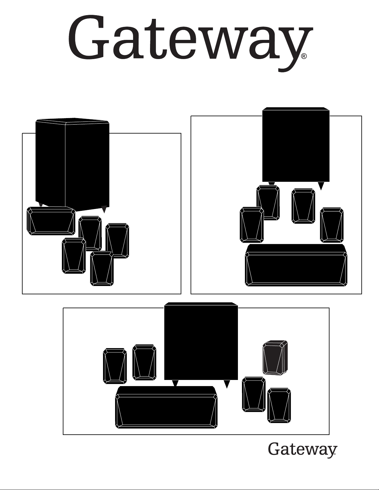
KAS-203
CC103
Center
SP103
2 Front
Satellites
KAS-303
System
SP303
2 Rear
Satellites
KAS-103
System
SW103
Subwoofer
SP103
2 Rear
Satellites
System
SW203
Subwoofer
SP303
2 Rear
Satellites
SP303
2 Front
Satellites
CC303
Center
SW303
Subwoofer
SP303
Rear
Center
CC303
Center
Video-Shielded Home Theater Speaker Systems by
Designed and engineered in the U.S.A.
SP303
2 Front
Satellites
Page 2
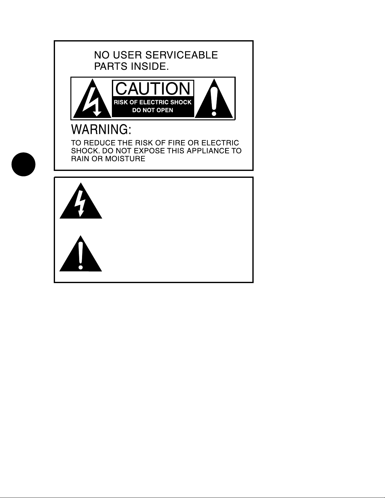
IMPORTANT SAFETY INSTRUCTIONS
2
1. Read these instructions — Read all the safety
and operation instructions before operating the
KAS-103/KAS-203/KAS-303 System.
2. Keep these instructions — Keep the safety
and operating instructions for future reference.
3. Heed all warnings — Follow all warnings on
the KAS-103/KAS-203/KAS-303 System and in
these operating instructions.
4. Follow all instructions — Follow all operating
and other instructions.
5. Do not use this apparatus near water — for
example, near a bathtub, washbowl, kitchen sink,
laundry tub, in a wet basement or near a
swimming pool.
6. Clean only with dry cloth.
7. Do not block any ventilation openings. Install in
accordance with the manufacturer’s instructions.
8. Do not install near any heat sources such as
radiators, heat registers, stoves, or other apparatus (including amplifiers) that produce heat.
9. Do not defeat the safety purpose of the polarized or grounding-type plug. A polarized plug has
two blades with one wider than the other. A
grounding-type plug has two blades and a third
The lightning flash with arrowhead symbol within an equilateral
triangle is intended to alert the user to the presence of uninsulated
“dangerous voltage” within the product’s enclosure that may be of
sufficient magnitude to constitute a risk of electric shock to persons.
Le symbole éclair avec point de flèche à l’intérieur d’un triangle
équilatéral est utilisé pour alerter l’utilisateur de la presence à
l’intérieur du coffret de “voltage dangereux” non isolé d’ampleur
suffisante pour constituer un risque d’éléctrocution.
The exclamation point within an equilateral triangle is intended to
alert the user to the presence of important operating and maintenance
(servicing) instructions in the literature accompanying the product.
Le point d’exclamation à l’intérieur d’un triangle équilatéral est
employé pour alerter les utilisateurs de la présence d’instructions
importantes pour le fonctionnement et l’entretien (service) dans le
livret d’instruction accompagnant l’appareil.
grounding prong. The wide blade or the third
prong are provided for your safety. If the provided plug does not fit into your outlet, consult an
electrician for replacement of the obsolete outlet.
10. Protect the power cord from being walked
on or pinched particularly at plugs, convenience
receptacles, and the point where they exit from
the apparatus.
11. Only use attachments/accessories specified
by the manufacturer.
12. Unplug this apparatus during lightning
storms or when unused for long periods of time.
13. Refer all servicing to qualified service personnel. Servicing is required when the apparatus has
been damaged in any way, such as power-supply
cord or plug is damaged, liquid has been spilled
or objects have fallen into the apparatus, the
apparatus has been exposed to rain or moisture,
does not operate normally, or has been dropped.
14. WARNING: To reduce the risk of fire or
electric shock, this apparatus should not be
exposed to rain or moisture and objects filled
with liquids, such as vases, should not be
placed on this apparatus.
15. To completely disconnect this equipment
from the mains, disconnect the power supply
cord plug from the receptacle.
16. The mains plug of the power supply cord
shall remain readily operable.
17. Connect the KAS-103/KAS-203/KAS-303
System to a power supply of the type described in these operation instructions or as
marked on the KAS-103/KAS-203/KAS-303
System.
18. To prevent electric shock, do not
use the KAS-103/KAS-203/KAS-303
System polarized plug with an extension cord, receptacle or other outlet
unless the blades can be fully inserted
to prevent blade exposure.
Pour préevenir les chocs électriques ne
pas utiliser cette fiche polariseé avec un
prolongateur, un prise de courant ou une
autre sortie de courant, sauf si les lames
peuvent être insérées à fond sans laisser
aucune pariie à découvert.
19. Internal/External Voltage Selectors —
Internal or external line voltage selector
switches, if any, should only be reset and reequipped with a proper plug for alternate
voltage by a qualified service technician.
This apparatus does not exceed the
Class A/Class B (whichever is applicable)
limits for radio noise emissions from digital apparatus as set out in radio interference regulations of the Canadian
Department of Communications.
ATTENTION — Le présent appareil
numérique n’émet pas de bruits
radioélectriques dépassant las limites
applicables aux appareils numériques de
class A/de class B (selon le cas) prescrites
dans le règlement sur le brouillage
radioélectrique édicté par les ministere
des communications du Canada.
TABLE OF
CONTENTS
A. UNPACKING . . . . . . . . . . .3
B. PLACEMENT . . . . . . . . . .3
C. SETUP . . . . . . . . . . . . . . .5
D. INITIAL LISTENING TESTS
AND ADJUSTMENTS . . . .7
E. TROUBLESHOOTING
AND SERVICE . . . . . . . . .8
F. SPECIFICATIONS . . . . . . .8
Page 3
A
B
UNPACKING
Carefully remove your new Gateway
speakers from their boxes, avoiding staples
which can cause damage to the cabinets.
Inspect each speaker for transit damage.
If you discover damage, contact Gateway
immediately.
Save your cartons – they are the best
possible protection for your speakers
should you ever have a need to move them.
®
®
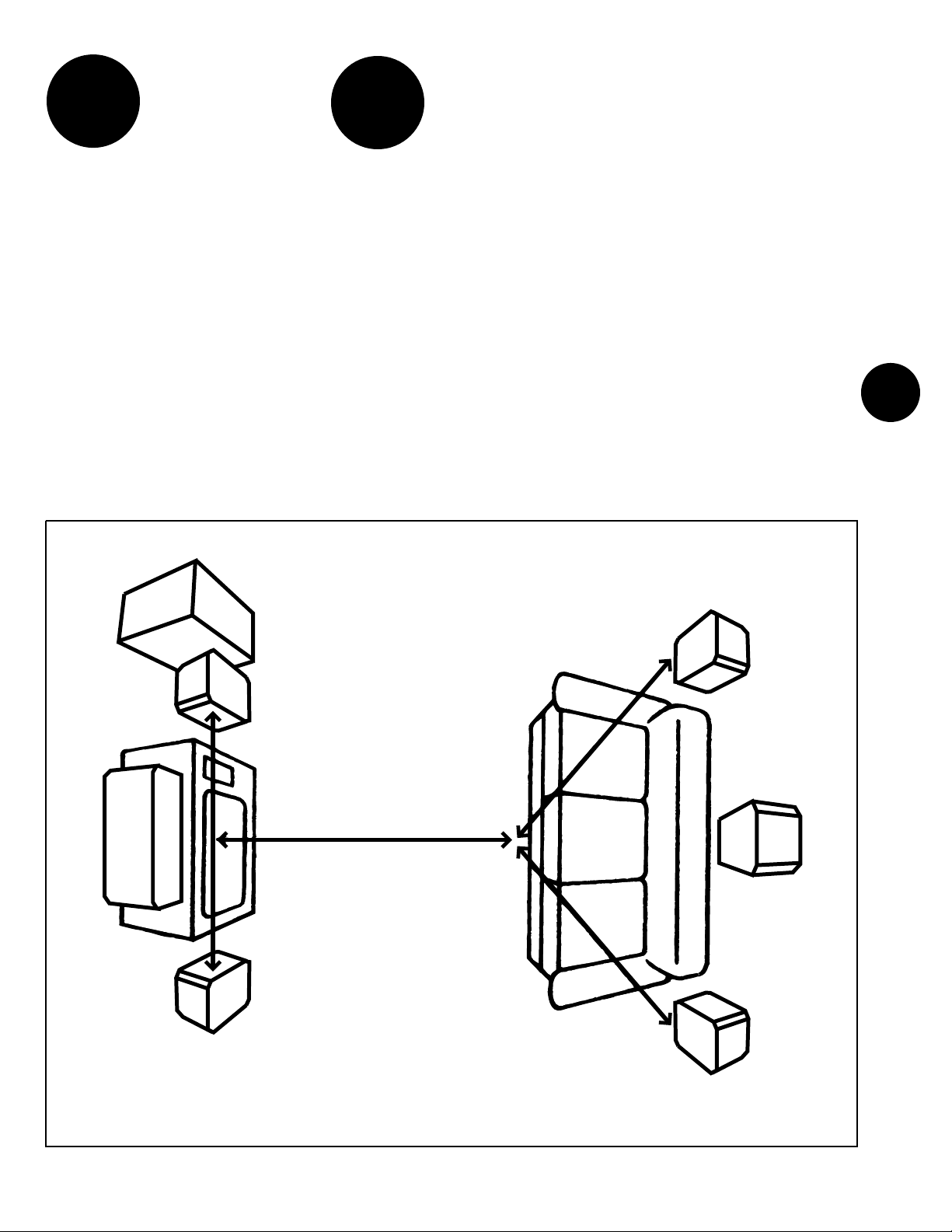
The Optimum Listening Position
4 or 5 Speaker Surround Sound Setup
SUBWOOFER
PLACEMENT
Positioning Your
Subwoofer
See the subwoofer owner’s manual.
Positioning Your
Satellites
Refer to Figure 1 for satellite speaker
placement. Front channel speakers
should be placed at least 6 feet apart to
create proper stereo imaging. The rear
channel surround speakers should be
positioned behind and slightly to the
sides of the viewer/listener. The rear center speaker should be positioned at the
3
REAR
SATELLITE
CENTER
FRONT
SATELLITE
FRONT
SATELLITE
REAR
CENTER*
*SP303
only on
KAS-303
system
REAR
SATELLITE
Figure 1
Page 4

same height as the two surround speakers,
but centered on the wall between them. It
may take some experimentation with different
locations for the surround speakers to suit
your preference and your room. The center
channel speaker should be placed as close to
the TV as possible, preferably directly above
or below the set.
Screw firmly
mounted
4
Each satellite is supplied with a mounting
bracket to allow hanging the speaker system
on the wall. All that is needed is a good solid
mount in the wall (into a wood stud if
possible) to securely hold the weight of
the speaker. Leave approximately 1/8˝ of a
screw head exposed from the wall and the
keyhole slot in the mounting bracket will
slide down over the head of the screw to
hang the speaker on the wall (Figure 2).
See Figure 3. The metal bracket supplied on the
rear of each satellite can be removed and an
aftermarket swivel-type satellite mount can be
used. Your Gateway®satellite speaker will
accommodate both the “Omnimount 10
Series” and the “Sound Gear SATP Series”
and other manufacturers’ mounts. Follow
the instructions included with the mount for
proper wall attachment.
Keyed slot
on satellite
Figure 2
1
/8˝
Wall
Aftermarket Speaker
Mounting Plate
Figure 3: Using an Aftermarket Swivel Mount
1
/4˝- 20 screws
Page 5

Setting Up Your
New KAS-103, KAS-203,
or KAS-303 System
Speakers
CAUTION: Make sure that you consult your
amplifier’s owner’s manual regarding
speaker setup. Your amplifier should be
turned off throughout this procedure.
C
SETUP
KAS-103 SETUP
IMPORTANT: Make certain all stereo
system components including the
subwoofer are turned OFF before
proceeding.
Refer to Figure 4 for proper connection.
Use the supplied male RCA to RCA line
level cable to connect the subwoofer to the
receiver. The satellites connect to the
receiver as shown with the red/black wires
supplied. Be sure to maintain proper
polarity when connecting the satellites and
center. Make sure the red wire goes to the
(+) positive and the black wire goes to the
(-) negative on both the receiver and
speaker.
5
Figure 4: KAS-103 Setup
Page 6
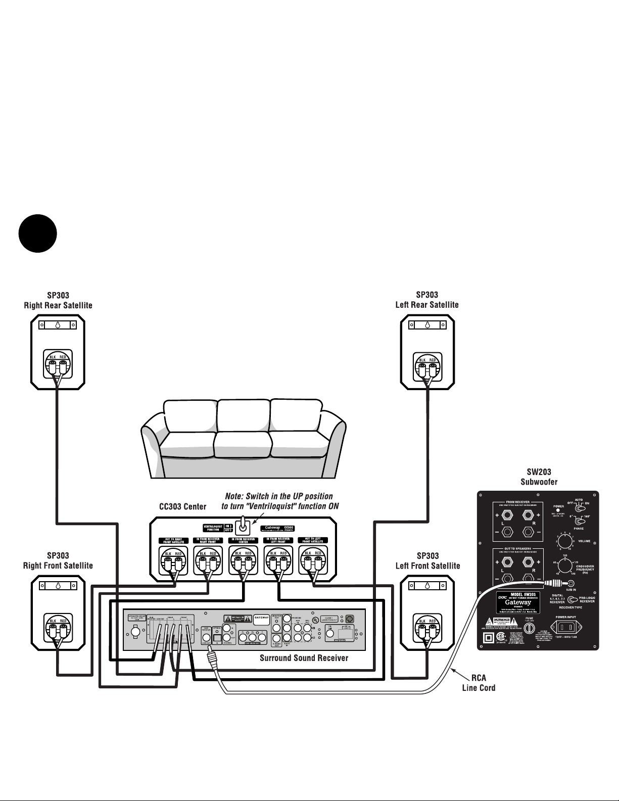
KAS-203, KAS-303
Setup
IMPORTANT: Make certain all stereo system components including the subwoofer
are turned OFF before proceeding.
Refer to Figures 5 and 6 for proper connection.
Use the supplied male RCA to RCA line level
cable to connect the subwoofer to the receiver.
The satellites connect to the receiver as shown
6
with the red/black wires supplied with your system. Be sure to maintain proper polarity when
connecting the satellites and center. Make sure
the red wire goes to the (+) positive and the
black wire goes to the (-) negative on both the
receiver and speaker. Note: The rear center
satellite is only used with the KAS-303 System.
CC303 Center
Setting up the center and front satellites is different than other standard speakers. Follow
thewiring diagram in Figures 5 and 6 closely
to produce the correct setup and to obtain
“Ventriloquist” operation. When wired as
shown and the switch on the upper center of
the center channel speaker is in the UP position you will experience the “Ventriloquist”
effect. This causes the small front satellites to
effectively sound like much larger bookshelf
speakers. When the switch is in the DOWN
position, the “Ventriloquist” function will be
turned off and the front satellites perform as
a standard 21/2˝ speaker.
Figure 5: KAS-203 Setup
Page 7

SP303
Right Front Satellite
SP303
Left Front Satellite
SP303
Right Rear Satellite
SP303
Left Rear Satellite
CC303 Center
SW303
Subwoofer
Surround Sound Receiver
RCA
Line Cord
Note: Switch in the UP position
to turn "Ventriloquist" function ON
CC303
#7004675
Designed & engineered in the U.S.A. Made in China
SP303
Center Rear Satellite
7
D
INITIAL
LISTENING
TEST
o 1. Double-check all connections.
o 2. Make sure that the volume controls
controls on both the subwoofer and
Figure 6: KAS-303 Setup
your receiver/integrated amp/preamp
are turned all the way down (fully
counter-clockwise).
o 3. Turn on your reciver. THEN turn on
the subwoofer. Confirm that the
subwoofer’s green POWER indicator
is glowing. If it isn’t, check the
power connections between the
subwoofer and the wall socket.
o 4. Play a musical selection that you are
familiar with. Pick a song that has
regular low bass beats. Advance the
receiver’s volume control up to a
normal listening level. If you don’t
hear sound through your main
speakers, turn off the system and
check connections.
o 5. If sound is coming out of your main
speakers, turn the subwoofer’s
VOLUME control clockwise until you
hear noticeable additional bass. If
you don’t hear bass by the time you
have advanced the subwoofer’s
VOLUME control halfway, turn off
the system and check connections.
Page 8

o 6. Some digital receivers only send a
subwoofer out signal when playing a
DVD or movie in the digital mode. In
the 2-channel (stereo music) mode,
no subwoofer out signal is sent to the
subwoofer. You may need to set your
main speakers to “small” mode in
your receiver setup to get the receiver’s
subwoofer out to turn on. Check
your receiver’s owner’s manual for
setup and subwoofer operation.
o 7. Adjust the subwoofer’s VOLUME control
until you are satisfied with the amount
of bass. You may want to try several
different tapes, compact discs or DVDs
while determining how high to adjust
8
the subwoofer VOLUME. The amount
of bass varies from disc to disc and
between different types of music.
o 8. After you are satisfied with the output of
your subwoofer, you can make all your
volume settings through your main
stereo system’s volume control. The
only time you might want to re-adjust
the subwoofer’s VOLUME is when you
encounter a musical selection that has
abnormally low – or high – bass.
KAS-103, KAS-203, KAS-303
F
Satellites
Video-shielded, 21/2˝ (6.4 cm) full range driven
Enclosure: . . . . . . . . . . . . . . . . . . . . . . . . . . . . . . . . Black vinyl laminated MDF
Dimensions: . . . . . . . . .53/4˝ (14.6 cm) H x 37/8˝ (9.8 cm) W x 31/2˝ (8.9 cm) D
Center-Channels
CC103: . . . . . . . . . . . . . . . .Video-shielded, two 21/2˝ (6.4 cm) full range drivers
CC303: . . . . . . . . . . . . .Video-shielded, two 4˝ (10.2 cm) x 6˝ (15.2 cm) woofers,
Enclosure: . . . . . . . . . . . . . . . . . . . . . . . . . . . . . . . . Black vinyl laminated MDF
Dimensions (CC103): . . . . . .35/8˝ (9.2 cm) H x 7˝ (17.8 cm) W x 33/4˝ (9.5 cm) D
Dimensions (CC303): . .51/4˝ (13.3 cm) H x 161/2˝ (41.9 cm) W x 83/4˝ (22.2 cm) D
Powered Subwoofers
SYSTEM SPECIFICATIONS
You can leave the SW103 in the ON mode,
and your SW203 or SW303 turned on and
in AUTO mode when not in use. It does
not draw much power in this state and
will be ready to add low bass the moment
you begin to play music. The SW103,
SW203, or SW303 will automatically go
into STANDBY mode after 10 to 20 minutes, when no music is playing.
However, if you’re not using your stereo
system for a long period of time (such as
when you’re on vacation), unplug the
subwoofer from the 120 volt AC wall plug.
A Word About
Power Handling
Remember, most amplifiers put out their
full rated power well before the volume
control is turned all the way up!
If your speakers distort when you play
them loud, turn down the amplifier.
one 21/2˝ (6.4 cm) mid-high driver
Caring for Your
Gateway®Speakers
The subwoofer and satellite cabinets are
finished with a very high quality polymer
laminate covering that is both attractive
and serves as an excellent protection for
the wood cabinet. The system can be
cleaned with a damp, soft cloth or you
may use a high-quality furniture polish to
maintain the original luster.
E
Troubleshooting
and Service
Gateway®speakers do not use external fuse
protection or circuit breakers because these
devices tend to impede sound quality and may
only protect the speaker to a marginal degree.
Rather, we use components and designs of the
highest caliber as an effective method of protecting the speaker. However, no amount of protection will prevent damage caused by defective
associated equipment or extreme abuse.
If you have a problem, first try to determine
if it is indeed a speaker problem. Determine
whether the problem exists in both speakers.
If its does, the problem likely originates in
some other component in the system. If the
problem is in one speaker only, reverse your
speaker leads (left to right, right to left). If
the problem moves to the other channel, your
problem is not in the speakers.
Once you have determined that you have a
speaker problem, contact your dealer for authorized factory service information. If you are
unable to contact your dealer, if your dealer
is unable to solve your problem, or if you have
any questions or comments regarding your
Gateway®Speaker System, contact us at:
See subwoofer owner’s manual
System Specifications (including subwoofers)
System Frequency Response (KAS-103 System): . . . . . . .36 Hz.- 18.5kHz +/- 3dB
System Frequency Response (KAS-203 System): . . . . . . . . .30Hz.- 18.5kHz +/- 3dB
System Frequency Response (KAS-303 System): . . . . . . .23Hz.- 18.5kHz +/- 3dB
Characteristic Sensitivity: . . . . . . . . . . . . . . . . . . . . . . . 90 dB @ 1 watt, 1 meter
Nominal Impedance: . . . . . . . . . . . . . . . . . . . . . . . . . . . . . . . . . . . . . . .8 ohms
©2003 Gateway
®
1-800-846-2301
Web site: www.gateway.com
Describe the problem in detail. We will decide
on the most appropriate course of action.
 Loading...