

Page 1

HomePortal 3801HGV Gateway User Guide
Release 1.0
Page 2

Notice to Users
©2005–2010 2Wire, Inc. All rights reserved. This manual in whole or in part, may not be reproduced, translated, or reduced to any machine-readable form without prior written approval.
2WIRE PROVIDES NO WARRANTY WITH REGARD TO THIS MANUAL, THE SOFTWARE, OR OTHER INFORMATION CONTAINED HEREIN AND HEREBY EXPRESSLY
DISCLAIMS ANY IMPLIED WARRANTIES OF MERCHANTABILITY OR FITNESS FOR ANY PARTICULAR PURPOSE WITH REGARD TO THIS MANUAL, THE SOFTWARE, OR
SUCH OTHER INFORMATION, IN NO EVENT SHALL 2WIRE, INC. BE LIABLE FOR ANY INCIDENTAL, CONSEQUENTIAL, OR SPECIAL DAMAGES, WHETHER BASED ON
TORT, CONTRACT, OR OTHERWISE, ARISING OUT OF OR IN CONNECTION WITH THIS MANUAL, THE SOFTWARE, OR OTHER INFORMATION CONTAINED HEREIN OR THE
USE THEREOF.
2Wire, Inc. reserves the right to make any modification to this manual or the information contained herein at any time without notice. The software described herein is governed by the terms of a
separate user license agreement.
Updates and additions to software may require an additional charge. Subscriptions to online service providers may require a fee and credit card information. Financial services may require prior
arrangements with participating financial institutions.
2Wire, the 2Wire logo, HomePortal, and MediaPortal are registered trademarks of 2Wire, Inc. All other trademarks are trademarks of their respective owners.
1202010
5100-000862-000
Page 3

Contents
About This Guide. . . . . . . . . . . . . . . . . . . . . . . . . . . . . . . . . . . . . . . . . . . . . . . . . . vi
Audience . . . . . . . . . . . . . . . . . . . . . . . . . . . . . . . . . . . . . . . . . . . . . . . . . . . . . . . . . . . . . vi
Using this Document . . . . . . . . . . . . . . . . . . . . . . . . . . . . . . . . . . . . . . . . . . . . . . . . . . . . vi
Style Conventions . . . . . . . . . . . . . . . . . . . . . . . . . . . . . . . . . . . . . . . . . . . . . . . . . . vii
Typographical Conventions . . . . . . . . . . . . . . . . . . . . . . . . . . . . . . . . . . . . . . . . . . . vii
Related Documents. . . . . . . . . . . . . . . . . . . . . . . . . . . . . . . . . . . . . . . . . . . . . . . . . . . . . vii
Support . . . . . . . . . . . . . . . . . . . . . . . . . . . . . . . . . . . . . . . . . . . . . . . . . . . . . . . . . . . . . .viii
CHAPTER 1 Introducing the HomePortal 3801HGV Gateway. . . . . . . . . . . . . . . . . . . . . . . . . . 1
Overview . . . . . . . . . . . . . . . . . . . . . . . . . . . . . . . . . . . . . . . . . . . . . . . . . . . . . . . . . . . . . .1
What the HomePortal 3801HGV Gateway Does for You . . . . . . . . . . . . . . . . . . . . . . . . .1
Components . . . . . . . . . . . . . . . . . . . . . . . . . . . . . . . . . . . . . . . . . . . . . . . . . . . . . . . . . . .2
CHAPTER 2
CHAPTER 3
CHAPTER 4
CHAPTER 5 Viewing Subscribed Services Status . . . . . . . . . . . . . . . . . . . . . . . . . . . . . . . . . . 17
CHAPTER 6 Configuring Voice-Based Services . . . . . . . . . . . . . . . . . . . . . . . . . . . . . . . . . . . 19
Installing the HomePortal 3801HGV Gateway . . . . . . . . . . . . . . . . . . . . . . . . . . . . 4
Determining HomePortal 3801HGV Gateway Location. . . . . . . . . . . . . . . . . . . . . . . . . . .4
Connecting the Power Adapter . . . . . . . . . . . . . . . . . . . . . . . . . . . . . . . . . . . . . . . . . . . . .5
Connecting Your Computer to the Gateway . . . . . . . . . . . . . . . . . . . . . . . . . . . . . . . . . . .5
Connecting through Local Ethernet . . . . . . . . . . . . . . . . . . . . . . . . . . . . . . . . . . . . . .5
Connecting through Wireless . . . . . . . . . . . . . . . . . . . . . . . . . . . . . . . . . . . . . . . . . . .6
Connecting the Broadband Interface. . . . . . . . . . . . . . . . . . . . . . . . . . . . . . . . . . . . . . . . .7
Connecting VoIP Interface. . . . . . . . . . . . . . . . . . . . . . . . . . . . . . . . . . . . . . . . . . . . . . . . .8
Connecting HPNA Interface to IPTV set top Box . . . . . . . . . . . . . . . . . . . . . . . . . . . . . . .9
Accessing the User Interface . . . . . . . . . . . . . . . . . . . . . . . . . . . . . . . . . . . . . . . . 11
System Link Tabs . . . . . . . . . . . . . . . . . . . . . . . . . . . . . . . . . . . . . . . . . . . . . . . . . . .12
Summary . . . . . . . . . . . . . . . . . . . . . . . . . . . . . . . . . . . . . . . . . . . . . . . . . . . . . . . . .12
Quick Service Links . . . . . . . . . . . . . . . . . . . . . . . . . . . . . . . . . . . . . . . . . . . . . . . . .12
Home Network Devices . . . . . . . . . . . . . . . . . . . . . . . . . . . . . . . . . . . . . . . . . . . . . .13
Top Networking Features . . . . . . . . . . . . . . . . . . . . . . . . . . . . . . . . . . . . . . . . . . . . .13
Configuring Internet Connection . . . . . . . . . . . . . . . . . . . . . . . . . . . . . . . . . . . . . 14
Viewing Status . . . . . . . . . . . . . . . . . . . . . . . . . . . . . . . . . . . . . . . . . . . . . . . . . . . . . . . . .19
Configuring SIP Server . . . . . . . . . . . . . . . . . . . . . . . . . . . . . . . . . . . . . . . . . . . . . . . . . .20
Configuring Phone Lines . . . . . . . . . . . . . . . . . . . . . . . . . . . . . . . . . . . . . . . . . . . . . . . . .22
Configuring Phones. . . . . . . . . . . . . . . . . . . . . . . . . . . . . . . . . . . . . . . . . . . . . . . . . . . . .23
Viewing External Line Statistics. . . . . . . . . . . . . . . . . . . . . . . . . . . . . . . . . . . . . . . . . . . .24
CHAPTER 7
Setting Up System Information . . . . . . . . . . . . . . . . . . . . . . . . . . . . . . . . . . . . . . 27
Viewing System Information . . . . . . . . . . . . . . . . . . . . . . . . . . . . . . . . . . . . . . . . . . . . . .27
Setting Up System Password . . . . . . . . . . . . . . . . . . . . . . . . . . . . . . . . . . . . . . . . . . . . .29
iii
Page 4

HomePortal 3801HGV Gateway User Guide Contents
Setting Default System Password . . . . . . . . . . . . . . . . . . . . . . . . . . . . . . . . . . . . . .29
Creating Your System Password . . . . . . . . . . . . . . . . . . . . . . . . . . . . . . . . . . . . . . .30
Configuring Date and Time . . . . . . . . . . . . . . . . . . . . . . . . . . . . . . . . . . . . . . . . . . . . . . .30
Automatically Setting up Date and Time . . . . . . . . . . . . . . . . . . . . . . . . . . . . . . . . .31
Manually Configuring Date and Time. . . . . . . . . . . . . . . . . . . . . . . . . . . . . . . . . . . .32
Enabling Event Notifications . . . . . . . . . . . . . . . . . . . . . . . . . . . . . . . . . . . . . . . . . . . . . .32
Enabling Notifications. . . . . . . . . . . . . . . . . . . . . . . . . . . . . . . . . . . . . . . . . . . . . . . .33
Disabling Notifications . . . . . . . . . . . . . . . . . . . . . . . . . . . . . . . . . . . . . . . . . . . . . . .33
CHAPTER 8
CHAPTER 9
Configuring Broadband Settings . . . . . . . . . . . . . . . . . . . . . . . . . . . . . . . . . . . . . 34
Viewing Broadband Status . . . . . . . . . . . . . . . . . . . . . . . . . . . . . . . . . . . . . . . . . . . . . . .34
Resetting Statistics on Status Page . . . . . . . . . . . . . . . . . . . . . . . . . . . . . . . . . . . . .40
Configuring Bridge Mode. . . . . . . . . . . . . . . . . . . . . . . . . . . . . . . . . . . . . . . . . . . . . . . . .40
Adding Static Routes. . . . . . . . . . . . . . . . . . . . . . . . . . . . . . . . . . . . . . . . . . . . . . . . . . . .42
Configuring IP Multicast Sessions . . . . . . . . . . . . . . . . . . . . . . . . . . . . . . . . . . . . . . . . . .43
Viewing Multicast Statistics . . . . . . . . . . . . . . . . . . . . . . . . . . . . . . . . . . . . . . . . . . . . . . .44
Resolving Domain Name. . . . . . . . . . . . . . . . . . . . . . . . . . . . . . . . . . . . . . . . . . . . . . . . .47
Configuring LAN Devices . . . . . . . . . . . . . . . . . . . . . . . . . . . . . . . . . . . . . . . . . . . 50
Viewing LAN Status. . . . . . . . . . . . . . . . . . . . . . . . . . . . . . . . . . . . . . . . . . . . . . . . . . . . .51
Setting Up Wireless Network. . . . . . . . . . . . . . . . . . . . . . . . . . . . . . . . . . . . . . . . . . . . . .53
Securing the Wireless Network Using Encryption Key . . . . . . . . . . . . . . . . . . . . . . . . . .55
Securing the Wireless Network Using MAC Filtering . . . . . . . . . . . . . . . . . . . . . . . . . . .57
Allowing MAC Addresses. . . . . . . . . . . . . . . . . . . . . . . . . . . . . . . . . . . . . . . . . . . . .58
Blocking MAC Addresses. . . . . . . . . . . . . . . . . . . . . . . . . . . . . . . . . . . . . . . . . . . . .59
Refreshing the List of Devices . . . . . . . . . . . . . . . . . . . . . . . . . . . . . . . . . . . . . . . . .60
Deleting the Devices . . . . . . . . . . . . . . . . . . . . . . . . . . . . . . . . . . . . . . . . . . . . . . . .60
Configuring Advance Wireless Settings . . . . . . . . . . . . . . . . . . . . . . . . . . . . . . . . . . . . .61
Configuring Wi-Fi Protected Setup . . . . . . . . . . . . . . . . . . . . . . . . . . . . . . . . . . . . . . . . .62
Setting Up WPS through the PIN Method . . . . . . . . . . . . . . . . . . . . . . . . . . . . . . . .62
Setting Up WPS through the Push Button Method . . . . . . . . . . . . . . . . . . . . . . . . .63
Configuring Local Ethernet Ports. . . . . . . . . . . . . . . . . . . . . . . . . . . . . . . . . . . . . . . . . . .64
Configuring HomePNA 3.1 . . . . . . . . . . . . . . . . . . . . . . . . . . . . . . . . . . . . . . . . . . . . . . .65
Viewing HomePNA Status . . . . . . . . . . . . . . . . . . . . . . . . . . . . . . . . . . . . . . . . . . . . . . . .66
Configuring DHCP. . . . . . . . . . . . . . . . . . . . . . . . . . . . . . . . . . . . . . . . . . . . . . . . . . . . . .66
Allocating IP Addresses . . . . . . . . . . . . . . . . . . . . . . . . . . . . . . . . . . . . . . . . . . . . . . . . .69
CHAPTER 10
CHAPTER 11
Contents iv
Configuring Firewall Settings. . . . . . . . . . . . . . . . . . . . . . . . . . . . . . . . . . . . . . . . 72
Viewing Firewall Status . . . . . . . . . . . . . . . . . . . . . . . . . . . . . . . . . . . . . . . . . . . . . . . . . .72
Configuring Firewall Settings. . . . . . . . . . . . . . . . . . . . . . . . . . . . . . . . . . . . . . . . . . . . . .73
Creating an Application Profile. . . . . . . . . . . . . . . . . . . . . . . . . . . . . . . . . . . . . . . . .75
Deleting User-defined Applications . . . . . . . . . . . . . . . . . . . . . . . . . . . . . . . . . . . . .79
Allowing all Applications. . . . . . . . . . . . . . . . . . . . . . . . . . . . . . . . . . . . . . . . . . . . . .79
Disabling Attack Detection. . . . . . . . . . . . . . . . . . . . . . . . . . . . . . . . . . . . . . . . . . . . . . . .80
Controlling Inbound and Outbound Traffic. . . . . . . . . . . . . . . . . . . . . . . . . . . . . . . . . . . .82
Configuring Firewall Security Enhancements . . . . . . . . . . . . . . . . . . . . . . . . . . . . . . . . .83
Configuring Application Layer Gateway . . . . . . . . . . . . . . . . . . . . . . . . . . . . . . . . . . . . .83
Viewing Logs . . . . . . . . . . . . . . . . . . . . . . . . . . . . . . . . . . . . . . . . . . . . . . . . . . . . . 85
Viewing Event Log. . . . . . . . . . . . . . . . . . . . . . . . . . . . . . . . . . . . . . . . . . . . . . . . . . . . . .85
Page 5

HomePortal 3801HGV Gateway User Guide Contents
Viewing All Event Logs. . . . . . . . . . . . . . . . . . . . . . . . . . . . . . . . . . . . . . . . . . . . . . .85
Filtering Logs . . . . . . . . . . . . . . . . . . . . . . . . . . . . . . . . . . . . . . . . . . . . . . . . . . . . . .87
Clearing Event Logs. . . . . . . . . . . . . . . . . . . . . . . . . . . . . . . . . . . . . . . . . . . . . . . . .87
Viewing System Log . . . . . . . . . . . . . . . . . . . . . . . . . . . . . . . . . . . . . . . . . . . . . . . . . . . .87
Filtering and Viewing System Logs . . . . . . . . . . . . . . . . . . . . . . . . . . . . . . . . . . . . .88
Inserting Mark . . . . . . . . . . . . . . . . . . . . . . . . . . . . . . . . . . . . . . . . . . . . . . . . . . . . .89
Clearing Logs . . . . . . . . . . . . . . . . . . . . . . . . . . . . . . . . . . . . . . . . . . . . . . . . . . . . . .89
Viewing Upgrade Log . . . . . . . . . . . . . . . . . . . . . . . . . . . . . . . . . . . . . . . . . . . . . . . . . . .89
Viewing Firewall Log . . . . . . . . . . . . . . . . . . . . . . . . . . . . . . . . . . . . . . . . . . . . . . . . . . . .90
Viewing Log . . . . . . . . . . . . . . . . . . . . . . . . . . . . . . . . . . . . . . . . . . . . . . . . . . . . . . .91
Clearing Log. . . . . . . . . . . . . . . . . . . . . . . . . . . . . . . . . . . . . . . . . . . . . . . . . . . . . . .92
CHAPTER 12
CHAPTER 13
Using Diagnostics Features . . . . . . . . . . . . . . . . . . . . . . . . . . . . . . . . . . . . . . . . . 93
Testing Broadband Link. . . . . . . . . . . . . . . . . . . . . . . . . . . . . . . . . . . . . . . . . . . . . . . . . .93
Viewing Link Tree . . . . . . . . . . . . . . . . . . . . . . . . . . . . . . . . . . . . . . . . . . . . . . . . . . . . . .95
Viewing DSL Diagnostic Information . . . . . . . . . . . . . . . . . . . . . . . . . . . . . . . . . . . . . . . .96
Testing IP Utilities . . . . . . . . . . . . . . . . . . . . . . . . . . . . . . . . . . . . . . . . . . . . . . . . . . . . . .97
Testing Ping . . . . . . . . . . . . . . . . . . . . . . . . . . . . . . . . . . . . . . . . . . . . . . . . . . . . . . .98
Testing Traceroute . . . . . . . . . . . . . . . . . . . . . . . . . . . . . . . . . . . . . . . . . . . . . . . . .100
Testing Dnsquery . . . . . . . . . . . . . . . . . . . . . . . . . . . . . . . . . . . . . . . . . . . . . . . . . .102
Viewing NAT Information . . . . . . . . . . . . . . . . . . . . . . . . . . . . . . . . . . . . . . . . . . . . . . . .103
Enabling Syslog. . . . . . . . . . . . . . . . . . . . . . . . . . . . . . . . . . . . . . . . . . . . . . . . . . . . . . .105
Resetting the Gateway . . . . . . . . . . . . . . . . . . . . . . . . . . . . . . . . . . . . . . . . . . . . . . . . .106
Resetting System and Links. . . . . . . . . . . . . . . . . . . . . . . . . . . . . . . . . . . . . . . . . .107
Resetting Configuration . . . . . . . . . . . . . . . . . . . . . . . . . . . . . . . . . . . . . . . . . . . . .108
Resetting Device to Factory Default. . . . . . . . . . . . . . . . . . . . . . . . . . . . . . . . . . . .108
Troubleshooting 3801HGV Gateway . . . . . . . . . . . . . . . . . . . . . . . . . . . . . . . . . 109
Connection Issues. . . . . . . . . . . . . . . . . . . . . . . . . . . . . . . . . . . . . . . . . . . . . . . . . . . . .109
VoIP Issues . . . . . . . . . . . . . . . . . . . . . . . . . . . . . . . . . . . . . . . . . . . . . . . . . . . . . . . . . .110
Home PNA Issues . . . . . . . . . . . . . . . . . . . . . . . . . . . . . . . . . . . . . . . . . . . . . . . . . . . . . 110
System Information Issues . . . . . . . . . . . . . . . . . . . . . . . . . . . . . . . . . . . . . . . . . . . . . . 111
Broadband Issues . . . . . . . . . . . . . . . . . . . . . . . . . . . . . . . . . . . . . . . . . . . . . . . . . . . . . 111
LAN Issues . . . . . . . . . . . . . . . . . . . . . . . . . . . . . . . . . . . . . . . . . . . . . . . . . . . . . . . . . .112
Firewall Issues. . . . . . . . . . . . . . . . . . . . . . . . . . . . . . . . . . . . . . . . . . . . . . . . . . . . . . . . 113
Diagnostic Issues . . . . . . . . . . . . . . . . . . . . . . . . . . . . . . . . . . . . . . . . . . . . . . . . . . . . .113
APPENDIX A
APPENDIX B Regulatory Information . . . . . . . . . . . . . . . . . . . . . . . . . . . . . . . . . . . . . . . . . . . . 117
Contents v
Glossary . . . . . . . . . . . . . . . . . . . . . . . . . . . . . . . . . . . . . . . . . . . . . . . . . . . . . . . . 114
Electrical . . . . . . . . . . . . . . . . . . . . . . . . . . . . . . . . . . . . . . . . . . . . . . . . . . . . . . . . . . . . 117
AC Adapter. . . . . . . . . . . . . . . . . . . . . . . . . . . . . . . . . . . . . . . . . . . . . . . . . . . . . . .117
Telecommunication Cord . . . . . . . . . . . . . . . . . . . . . . . . . . . . . . . . . . . . . . . . . . . .117
Internal Telephone ports (VoIP) . . . . . . . . . . . . . . . . . . . . . . . . . . . . . . . . . . . . . . . 117
Location – Electrical Considerations . . . . . . . . . . . . . . . . . . . . . . . . . . . . . . . . . . . 117
Equipment . . . . . . . . . . . . . . . . . . . . . . . . . . . . . . . . . . . . . . . . . . . . . . . . . . . . . . . 118
Declaration of Conformity . . . . . . . . . . . . . . . . . . . . . . . . . . . . . . . . . . . . . . . . . . . . . . .118
FCC / Industry Canada Compliance . . . . . . . . . . . . . . . . . . . . . . . . . . . . . . . . . . .118
Part 15 of FCC Rules . . . . . . . . . . . . . . . . . . . . . . . . . . . . . . . . . . . . . . . . . . . . . . . 118
TIA 968 (Part 68 of FCC Rules) / IC CS-03 . . . . . . . . . . . . . . . . . . . . . . . . . . . . . .119
MPE/SAR/RF Exposure Information . . . . . . . . . . . . . . . . . . . . . . . . . . . . . . . . . . .119
Page 6

About This Guide
The HomePortal 3801HGV Gateway Installation and Configuration Guide is designed to serve as a
reference to install and set up the HomePortal 3801HGV gateway. This guide contains the following
major sections:
Introducing the HomePortal 3801HGV Gateway on page 1
Installing the HomePortal 3801HGV Gateway on page 4
Accessing the User Interface on page 11
Configuring Internet Connection on page 14
Viewing Subscribed Services Status on page 17
Configuring Voice-Based Services on page 19
Setting Up System Information on page 27
Configuring Broadband Settings on page 34
Configuring LAN Devices on page 50
Configuring Firewall Settings on page 72
Using Diagnostics Features on page 93
Troubleshooting 3801HGV Gateway on page 109
Glossary on page 114
Regulatory Information on page 117
Audience
This guide is intended for use by:
• End Users
• Sales Engineers
• Support Staff
• Service Provider Technicians
Using this Document
Each topic/subtopic in this document has the following sections:
• Objective
• Steps
• See Also
vi
Page 7

HomePortal 3801HGV Gateway User Guide About This Guide
These sections help you find your topics of interest with ease, and guide you through the topics in
a simple and logical manner.
The See Also section has cross-referenced links to other topics within this document, which may
assist you in further understanding your device.
Style Conventions
The following style conventions are used in this document:
Note Notes contain incidental information about the subject. In this guide, they are used to
provide additional information about the product, and to call attention to exceptions.
m
c
Caution notes identify information that helps prevent damage to hardware or loss of
data.
Warning notes identify information that helps prevent injury or death.
Typographical Conventions
The following typographical conventions are used in this document:
Convention Used For
Blue Text Cross references
Bold Interface elements that are clicked or selected
Italic Emphasis, book titles, variables, list terms
Monospace Command syntax and code
Monospace Italic Variables within command syntax and code
Related Documents
In addition to this guide, the HomePortal 3801HGV gateway documentation library includes:
• HomePortal 3801HGV Hardware Functional Specifications: Communicates the high level
hardware related information
• HomePortal 3801HGV Software Functional Specifications: Communicates the high level
features of the gateway
• HomePortal 3801HGV Hardware Release Notes: Communicates the hardware changes
incorporated in the latest release
• HomePortal 3801HGV Software Release Notes: Communicates the known issues, resolved
issues, and feature updates in the latest release
Related Documents vii
Page 8

HomePortal 3801HGV Gateway User Guide About This Guide
Support
Technical support is available from the 2Wire Website: http://support.2wire.com/index.php.
Support viii
Page 9

CHAPTER 1
Introducing the HomePortal 3801HGV Gateway
Welcome to the 2Wire family. The HomePortal 3801HGV gateway belongs to the next generation
gateway series that delivers profound user experience with its easy-to-use features. This gateway
helps you connect to your ISP, and also to achieve a host of functions, which makes your home
network safe, convenient, and greatly enjoyable!
This chapter offers an overview of the HomePortal 3801HGV gateway, and describes its key
features.
Overview
The 2Wire HomePortal 3801HGV gateway is an advanced gateway that either the service provider
or the subscriber can install.
It is a home networking device that provides an 802.11b/g Wi-Fi access point and switching
functions for connecting personal computers and other home-networked devices to the service
provider network. The gateway has 4 10/100 Ethernet ports to connect to computers or devices in
the home. It comes loaded with hardware capabilities that enable you to use VoIP and Video
Streaming technologies.
What the HomePortal 3801HGV Gateway Does for You
The HomePortal 3801HGV gateway gives you a seamless, high speed Internet access, amongst a
host of other features:
• Seamless Wireless Connectivity: The gateway includes an integrated wireless access point
that allows you to roam wirelessly throughout the home or office. 2Wire high-powered
wireless technology helps to reduce wireless “cold spots” in the home. The high-power
400mW transmitter of the gateway increases wireless bandwidth throughout the coverage
area
• Home Networking: Share files, printers, and a broadband connection with every computer
and other network-ready device in the home or small office through the advanced LAN
technology. There are 4 Ethernet ports you can use to connect to multiple devices in your
network
1
Page 10

HomePortal 3801HGV Gateway User Guide Introducing the HomePortal 3801HGV Gateway
• Parental Controls (Internet Access Controls and Content Screening): Parental controls offer
easy-to-use tools to limit access to specific Websites, monitor browsing history and usage,
and enforce time restrictions on common applications. Parental control settings are
straightforward and easily managed by users. Because this service resides at the gateway,
every Internet device on the network can be protected—even visiting devices
• Advanced Firewall Monitoring: This feature watches for suspicious activity, helping to
eliminate security issues before they have a chance to proliferate. It automatically keeps
itself current with software updates. You can decide when and how to receive notification of
attacks and view detailed logs through the gateway’s user interface
• Web Remote Access: You can gain fast, easy access to your local network remotely using
an Internet browser. Download files securely from anywhere using an Internet connection
and network password. You can also view and manage all gateway settings, including those
for other applications like Parental Controls and Firewall Monitoring
• Voice Over IP (VoIP): Two FXS lines through an RJ-14 jack provide prioritized VoIP services,
lowering your communication costs. This gateway also supports wireless-wireline
convergence
• HomePNA (HPNA): HPNA features for distributing entertainment and triple play data over
existing coax cables
• Network Address Translation (NAT): NAT and Network Address and Port Translation (NAPT)
technology for enabling multiple hosts on private network using a common IP address
• Internet Protocol Security (IPsec): IPsec for protecting data flows between a pair of hosts,
between a pair of security gateways, or between a security gateway and a host
• Internet Group Management Protocol (IGMP): IGMP and IGMP Proxying for NAT and firewall
traversal
• Domain Name Server (DNS): Acts as a DNS name server to LAN devices, letting you set a
simple domain name for devices instead of keeping track of their respective IP addresses
• QoS (Quality of Service): QoS features such as policies, priority queuing, shaping, and
management allows you effectively manage the available Internet bandwidth
• Logs: The gateway maintains an internal log of broadband status and WAN-side connection
flows, letting you or the ISP’s technician effectively diagnose issues
• PING Client: To ping LAN and WAN side IP addresses within your network. This lets you
know whether a device is responding or not
• The HomePortal 3801HGV gateway comes loaded with a user-friendly Web interface that
allows you to configure your gateway settings as per your requirements
Components
Before installing your gateway, review the package content and ensure that you have items
available as shown below.
Note The gateway and the stand are packaged separately in the container. Vertical orientation is
the preferred method for mounting the HomePortal 3801HGV gateway.
Components 2
Page 11
HomePortal 3801HGV Gateway User Guide Introducing the HomePortal 3801HGV Gateway
Figure 1: Installation Components
Your HomePortal 3801HGV gateway has the following components in the box:
• 1 HomePortal 3801HGV Gateway
• 1 Power Cord & Adapter
See Also
Installing the HomePortal 3801HGV Gateway on page 4
Accessing the User Interface on page 11
Configuring Internet Connection on page 14
Regulatory Information on page 117
Components 3
Page 12

CHAPTER 2
Installing the HomePortal 3801HGV Gateway
Installing your HomePortal 3801HGV gateway consists of the following tasks:
• Determining HomePortal 3801HGV Gateway Location on page 4
• Connecting the Power Adapter on page 5
• Connecting Your Computer to the Gateway on page 5
• Connecting the Broadband Interface on page 7
• Connecting VoIP Interface on page 8
• Connecting HPNA Interface to IPTV set top Box on page 9
Determining HomePortal 3801HGV Gateway Location
If you have subscribed for IPTV and High Speed Internet, then the preferred location for installing
the HomePortal 3801HGV gateway is near the first video set top box. If you have subscribed only
for High Speed Internet access, then the HomePortal 3801HGV gateway should be installed near
the first computer.
Also, you must determine a Wireless Access Point (WAP) location to deploy the HomePortal
3801HGV gateway. Wireless signals are affected by many items in homes and offices. Reliability
and performance are the major considerations when planning your wireless network location.
Consider the following points before determining the WAP to deploy the gateway:
• Place your gateway at least 5 feet (1.52 meters) from cordless phones, microwave ovens,
or other electronic devices to avoid potential interference, and more than 6 inches (15.24
centimeters) away from your television to avoid audio hissing or static
• Place the gateway in an open area where the wireless range will not be directly affected by
the surroundings. Wireless signal strength will be much stronger in an open area as
opposed to an area with obstructions. In a single-story building, place the gateway as high
and as close to each wireless computer as possible
• Keep the gateway away from any large metal objects. Wireless signal quality may be
adversely affected as metal objects can reflect or obstruct signals
Note Whenever possible, use the stand provided with the gateway, and install it in the vertical
position. Make sure that it is installed in a manner that nothing can be stacked on the top
of it. Vertical orientation is the preferred method for mounting the HomePortal 3801HGV
gatewaygateway.
4
Page 13
HomePortal 3801HGV Gateway User Guide Installing the HomePortal 3801HGV Gateway
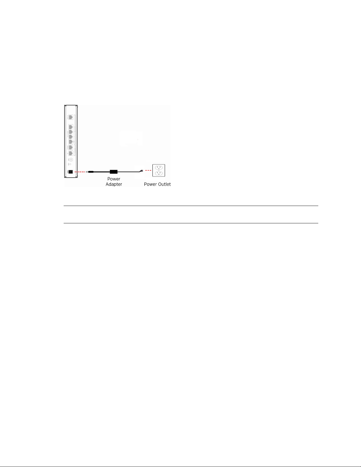
Connecting the Power Adapter
Follow these steps to power on the gateway:
1. Connect one end of the power adapter to the POWER port of your gateway.
2. Connect the other end of the power adapter to an electrical outlet. Once the gateway is
powered on, the power LED flashes green for a brief period of time and then turns solid
green.
Figure 2: Power Connection
Note Use the 2Wire power adapter packaged with the gateway, as it is compliant with local
regulatory requirements.
Connecting Your Computer to the Gateway
The first computer you connect to the gateway is used to configure the HomePortal 3801HGV
gateway for proper operation. You can connect your gateway to additional computers and/or other
devices with Ethernet cable and wireless AP.
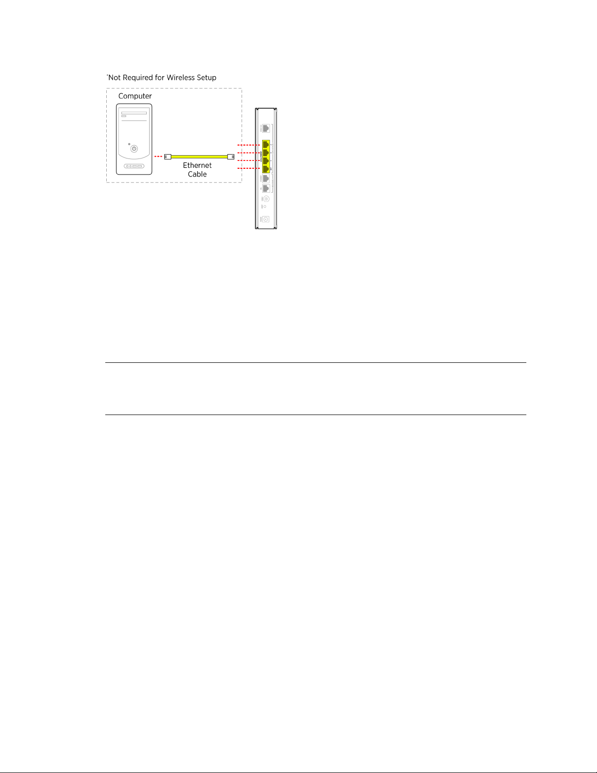
Connecting through Local Ethernet
The HomePortal 3801HGV gateway has four Ethernet ports for directly connecting computers or
devices. Use the Ethernet interface(s) on the gateway to create a broadband network. Follow these
steps to connect the computer to the gateway using the Ethernet cable:
1. Connect one end of the Ethernet cable (yellow) to any available LOCAL ETHERNET port on
the gateway.
2. Connect the other end of the Ethernet cable to the Ethernet port of the Network Interface
Card (NIC) on the computer.
Connecting the Power Adapter 5
Page 14
HomePortal 3801HGV Gateway User Guide Installing the HomePortal 3801HGV Gateway
Figure 3: LAN Connection
Connecting through Wireless
The HomePortal 3801HGV gateway has an integrated wireless access point (AP) that enables you
to connect your wireless-enabled computers to your gateway. By default, the HomePortal 3801HGV
gateway is shipped with WPA-PSK/WPA2-PSK enabled and a preconfigured network name.
Most laptops are equipped with an internal 802.11b/g card. If your computer is not equipped with
an internal card, you can install an external wireless adapter for wireless networking.
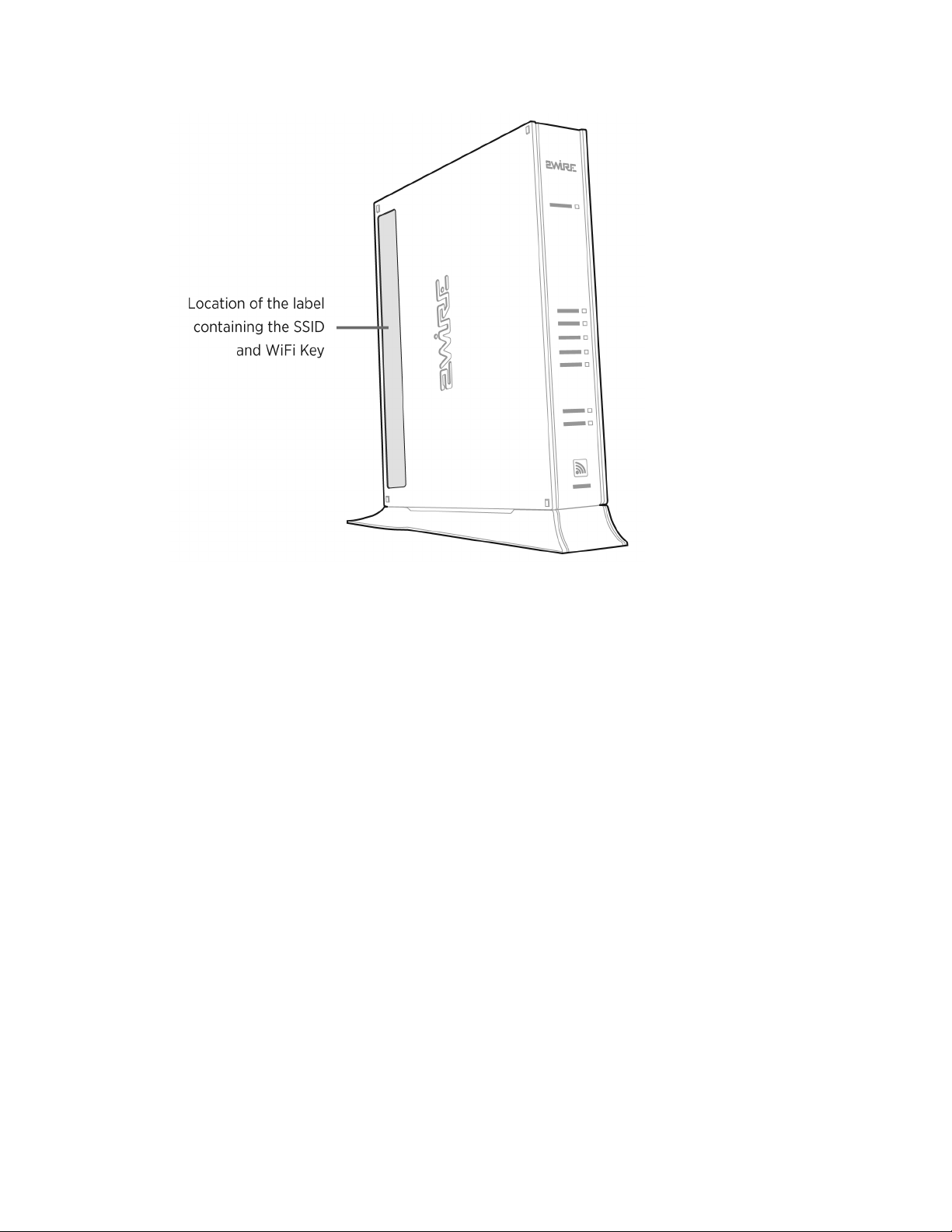
Note The default network name (SSID) is the encryption key, a 64-bit hex value located beneath
the bar code on the side of the 2Wire gateway (for example, 1234567891). For Mac OS X
users, you may need to enter the “$” character at the beginning of the encryption key (for
example, $1234567891).
Follow these steps to connect the computer to the gateway using Wireless:
1. Push the wireless button at the bottom of the gateway front panel. Verify that the
WIRELESS light on the front of the HomePortal 3801HGV gateway is solid green.
2. Install and configure your wireless adapter, if required.
3. View the available wireless network connections. Use the network adapter client or
Windows Wireless Network Connection wizard to do so.
4. Select the network name of the gateway from the menu, and click Connect. A prompt to
enter the network key appears.
5. Enter the encryption key and click Connect. Refer the note above for the location of the key.
Connecting Your Computer to the Gateway 6
Page 15
HomePortal 3801HGV Gateway User Guide Installing the HomePortal 3801HGV Gateway
Figure 4: Wireless Network Key Location
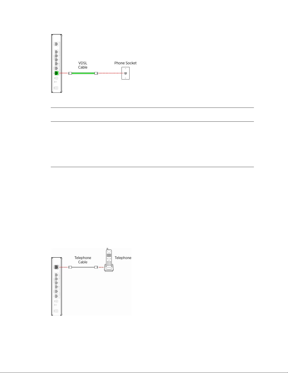
Connecting the Broadband Interface
Follow these steps to connect the gateway to Very High Bit-rate DSL (VDSL) wall jack:
1. Connect one end of the phone cord/twisted pair cable to the DSL port (green) on your
gateway.
2. Connect the other end of the phone cord/twisted pair cable to the VDSL enabled wall jack
outlet. Once the gateway recognizes the VDSL connection, Broadband LED flashes green
for a brief period of time, and then turns solid green.
Connecting the Broadband Interface 7
Page 16
HomePortal 3801HGV Gateway User Guide Installing the HomePortal 3801HGV Gateway
Figure 5: VDSL Broadband Connection
Note The HomePortal 3801HGV gateway must be connected to the VDSL wall jack. Do not
connect the DSL port of the HomePortal 3801HGV gateway to a telephone wall jack.
Connecting VoIP Interface
The HomePortal 3801HGV gateway includes one RJ-14 port (Voice 1 & 2) with the capacity to
support 2 phone lines using a splitter or multi-jack adapter.
c Warning: Do not connect the VoIP lines to your current home telephone wiring without
contacting your service provider. This requires special installation, especially if your home
has an alarm system, which requires special wiring.
Follow these steps to connect the VoIP phone to the Voice 1 & 2 port of the gateway:
1. To connect 1 phone:
a. Connect one end of the phone cable to the HomePortal 3801HGV gateway Voice 1&2
port.
b. Connect the other end of the phone cable to the phone jack.
Figure 6: VoIP Connection without Splitter
Connecting VoIP Interface 8
Page 17

HomePortal 3801HGV Gateway User Guide Installing the HomePortal 3801HGV Gateway
2. To connect 2 phones:
a. Connect one end of the line splitter to the HomePortal 3801HGV gateway Voice 1&2
port.
b. Connect the phone cables to the first and second jack of the splitter.
Figure 7: VoIP Connection Using Splitter
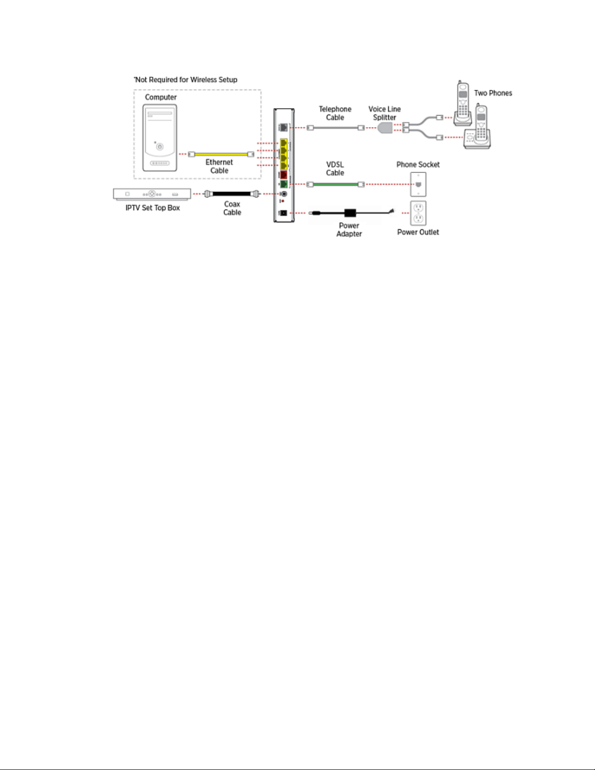
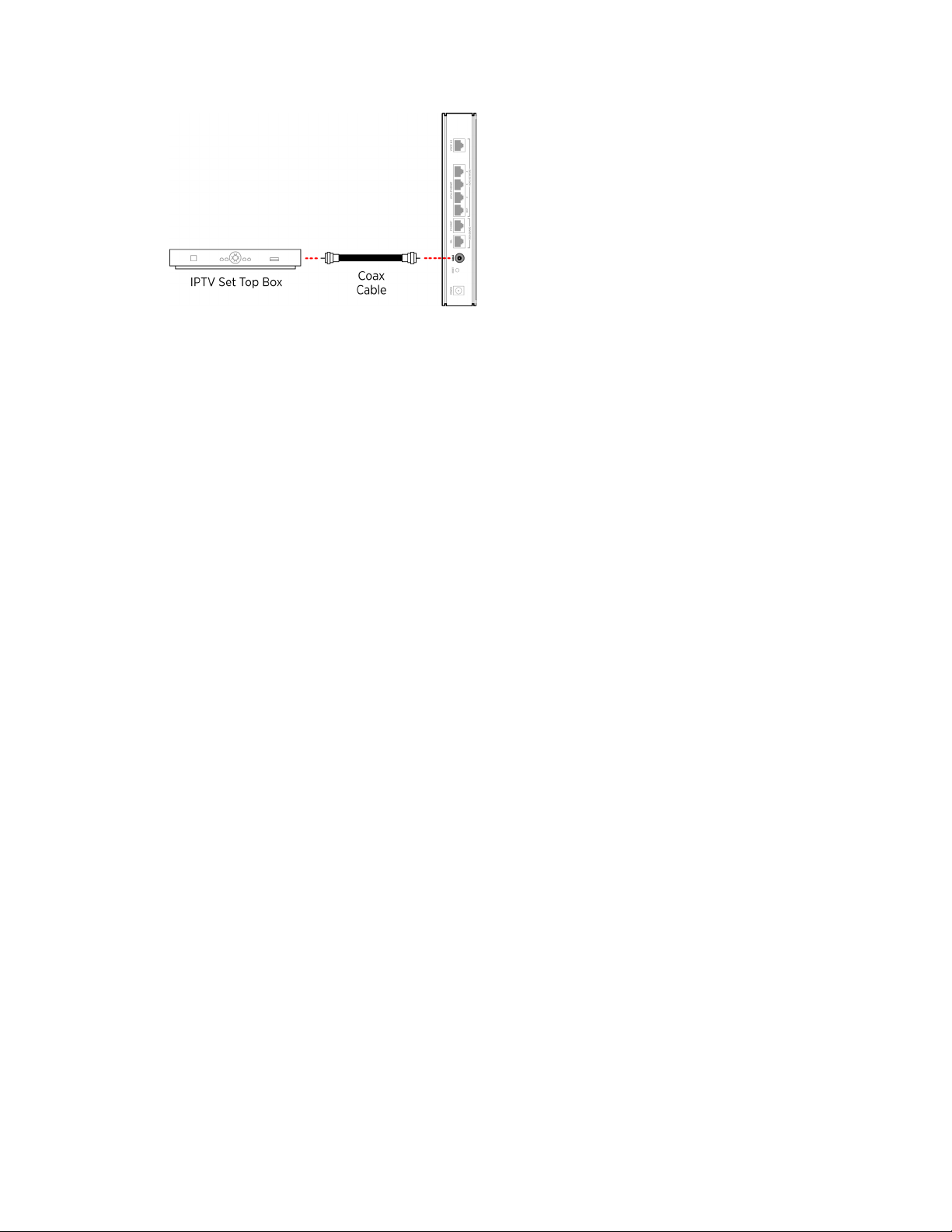
Connecting HPNA Interface to IPTV set top Box
The HomePortal 3801HGV gateway can be configured to use IPTV services through the cable port.
Follow these steps to connect the gateway to the set top box:
1. Connect one end of the coaxial cable to the CABLE port and the other end to the CABLE IN
port of Ethernet over Coax adapter.
2. Connect one end of the Ethernet cable to the Ethernet port of Ethernet over Coax adapter
and the other end to the Ethernet port on the set top box.
Note The Ethernet over Coax adapter is independently powered, and should be installed close to
a power outlet. Refer to the manufacturer’s instructions that came with the Ethernet over
Coax adapter.
Connecting HPNA Interface to IPTV set top Box 9
Page 18
HomePortal 3801HGV Gateway User Guide Installing the HomePortal 3801HGV Gateway
Figure 8: IPTV Connection VDSL over Coax
See Also
Introducing the HomePortal 3801HGV Gateway on page 1
Accessing the User Interface on page 11
Connecting HPNA Interface to IPTV set top Box 10
Page 19

CHAPTER 3
Accessing the User Interface
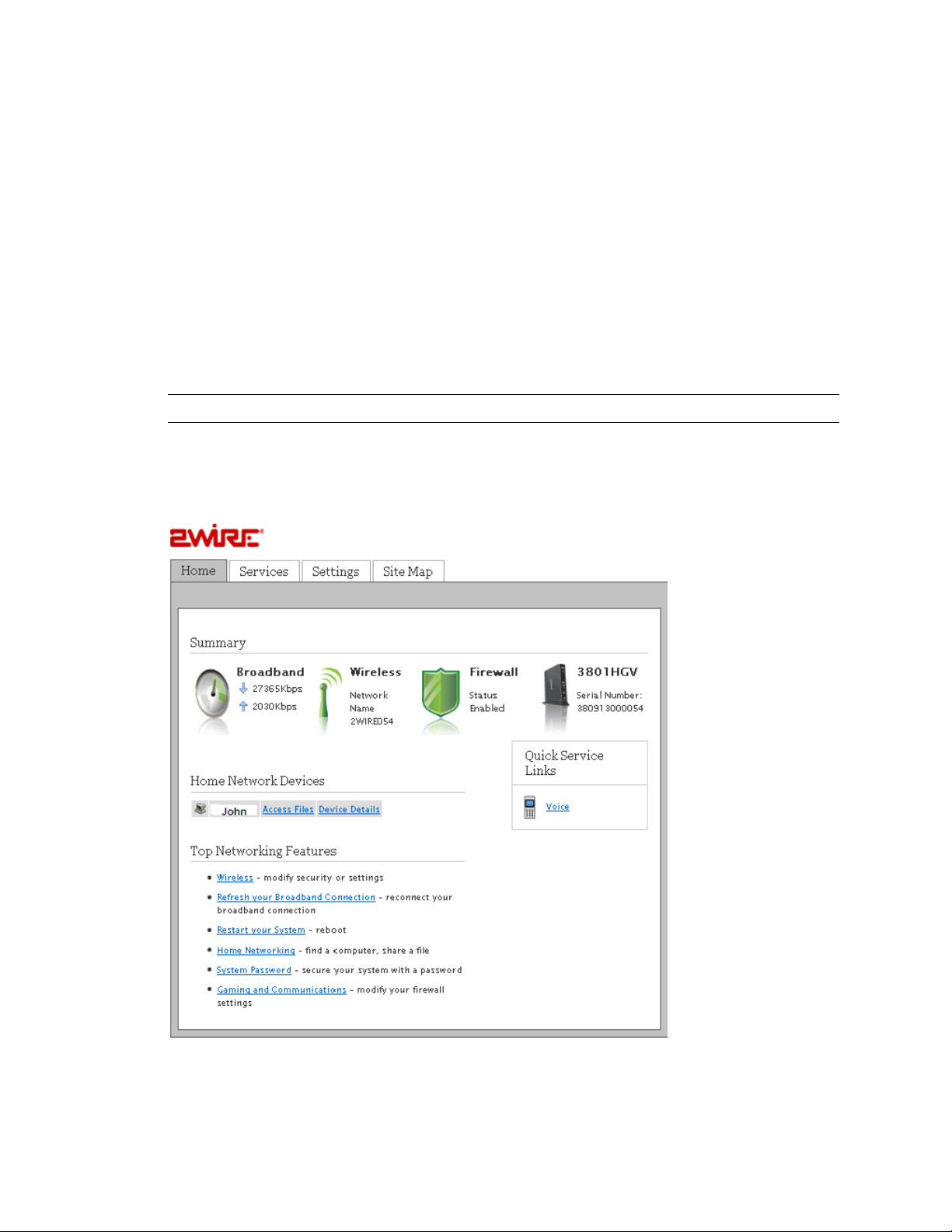
To launch the HomePortal 3801HGV gateway user interface, access the Home page of the gateway
by entering one of the following URLs into a compatible browser on the computer connected to the
gateway:
• http://gateway.2Wire.net
• http://home
• http://192.168.1.254
The Home page appears.
11
Page 20

HomePortal 3801HGV Gateway User Guide Accessing the User Interface
The Home page has the following five panes:
• System Link Tabs
•Home
•Services
• Settings
•Site Map
•Summary
• New TELCO Services Features
• Quick Service Links
• Home Network Devices
• Top Networking Features
System Link Tabs
Home
The Home tab provides the most relevant information about your broadband service at a glance. It
also provides links to access more detailed information.
Services
The Services tab provides links to view the status of file sharing, Web servers, VoIP, and IPTV
services. You can also configure your VoIP interfaces and view the VoIP interface status and
statistics.
Settings
The Settings tab provides links to view and configure system information. Also, other sub-tabs let
you configure Broadband services, LAN settings, Firewall settings, and perform Diagnostics on your
gateway.
Site Map
The Site Map tab provides a tree-diagram view of the user interface. Click any link on this page to
access the relevant page. This helps you to access the desired page directly without having to
navigate through the nesting on the system link tabs.
Summary
The Summary pane displays the bandwidth status beside the Broadband icon, network name
(SSID) of the gateway beside the Wireless icon, security status beside the Firewall icon, and serial
number beside the gateway icon. Click an icon to access the relevant page directly.
Quick Service Links
The Quick Service Links pane displays the Voice link. Click the link to access the Voice page
directly.
12
Page 21

HomePortal 3801HGV Gateway User Guide Accessing the User Interface
Home Network Devices
The Home Network Devices pane displays all devices that are connected to the gateway. You
can click the links to view the device details or view the shared files of the connected devices.
Top Networking Features
The Top Networking Features pane provides shortcuts to directly access the most commonly used
gateway pages. Click a link to access the relevant page directly.
See Also
Introducing the HomePortal 3801HGV Gateway on page 1
Installing the HomePortal 3801HGV Gateway on page 4
Configuring Internet Connection on page 14
13
Page 22
CHAPTER 4
Configuring Internet Connection
Objective
To configure the Internet connection on the gateway.
You must have PPP Authentication credentials to complete this configuration. Also, ensure the
Broadband LED on the front panel of the gateway is solid green and the first computer is
communicating with the gateway.
Note PPP credentials are provided by your ISP.
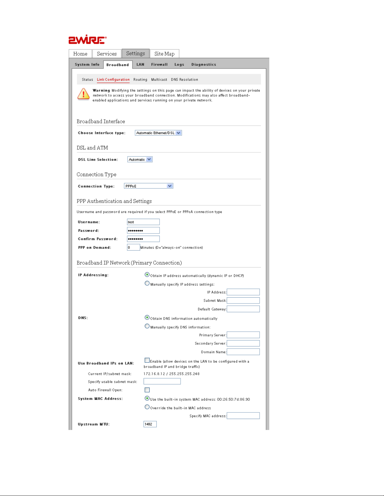
Steps
1. Access the Home page of the gateway.
2. Navigate to Settings > Broadband > Link Configuration. The Link Configuration page
appears.
14
Page 23
HomePortal 3801HGV Gateway User Guide Configuring Internet Connection
15
Page 24

HomePortal 3801HGV Gateway User Guide Configuring Internet Connection
3. Select Automatic Ethernet/DSL from the Choose Interface Type drop-down list. This
enables the gateway to automatically detect the type of connection used to connect to the
Broadband service.
4. Select Automatic from the DSL Line Selection drop-down list. This lets you select RJ-11 or
coax interface for connecting the DSL connection to your gateway.
5. Select PPPoE from the Connection Type drop-down list. PPPoE user credentials
authenticate the subscriber on the server of the ISP.
6. Enter the PPPoE Username and Password in the PPP Authentication and Settings section.
This information is provided by the ISP.
7. Leave the PPP on Demand field as is, unless otherwise indicated by your ISP. If you
increase the value, the Internet connection becomes idle after that duration.
8. Leave the selected radio buttons Obtain IP address automatically (dynamic IP or DHCP)
and Obtain DNS information automatically in the Broadband IP Network (Primary
Connection) section as they are, if you do not want to configure the associated information
statically.
Contact your ISP to get associated information for configuring IP address and DNS
statically.
9. Leave the Use Broadband IPs on LAN and System MAC Address settings as they are, if
you do not want to enable bridging on your gateway.
10. Leave the Upstream MTU value as is. This is the maximum size allowed on data packets,
that are communicated on the network of your ISP.
11. Click Save. The Internet LED on the gateway becomes solid green and you can access the
Internet.
12. Open a Web browser and access www.google.com.
See Also
Introducing the HomePortal 3801HGV Gateway on page 1
Installing the HomePortal 3801HGV Gateway on page 4
Accessing the User Interface on page 11
16
Page 25
CHAPTER 5
Viewing Subscribed Services Status
NOTE TO REVIEWER: We need images of the Status tab with all services enabled.
We also need information about the following sections: Web Servers, TELCO Digital Voice, TELCO
TV. What do these sections display? Will the user be able to see all these sections if he has not
subscribed for a particular service?
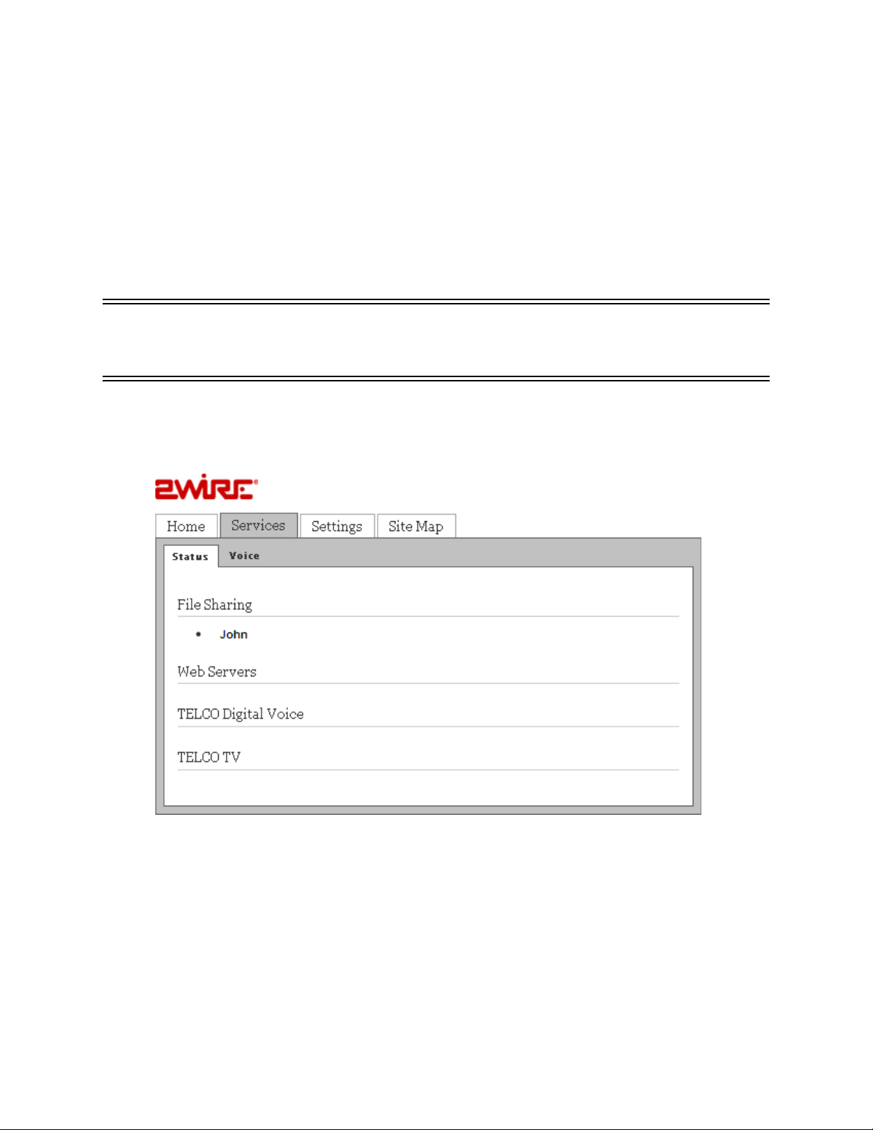
This chapter provides information about the Status tab. You can view the status of your subscribed
services in this tab.
To view the Status tab, navigate to Services > Status. The File Sharing page appears.
Click Remote Access configuration link to enable Web remote access on your system.
17
Page 26

HomePortal 3801HGV Gateway User Guide Viewing Subscribed Services Status
Refer to the following table for description of the parameters listed on the Status page:
Parameter Description
File Sharing Displays all devices connected to the HomePortal 3801HGV gateway. You can
Web Servers Displays the Web servers configured to the gateway.
TELCO Digital Voice Displays the status of the VoIP lines and associated servers.
TELCO TV Displays the IPTV parameters.
share files among these devices.
18
Page 27

CHAPTER 6
Configuring Voice-Based Services
This chapter provides information about the tasks that you can perform in the Voice tab. Following
are the links under the Voi ce tab, and associated tasks:
• Status
• Viewing Status on page 19
•Server
• Configuring SIP Server on page 20
•Line
• Configuring Phone Lines on page 22
• Phone
• Configuring Phones on page 23
• Stats
• Viewing External Line Statistics on page 24
Note You can access this tab only if you have subscribed for the VoIP service from your provider.
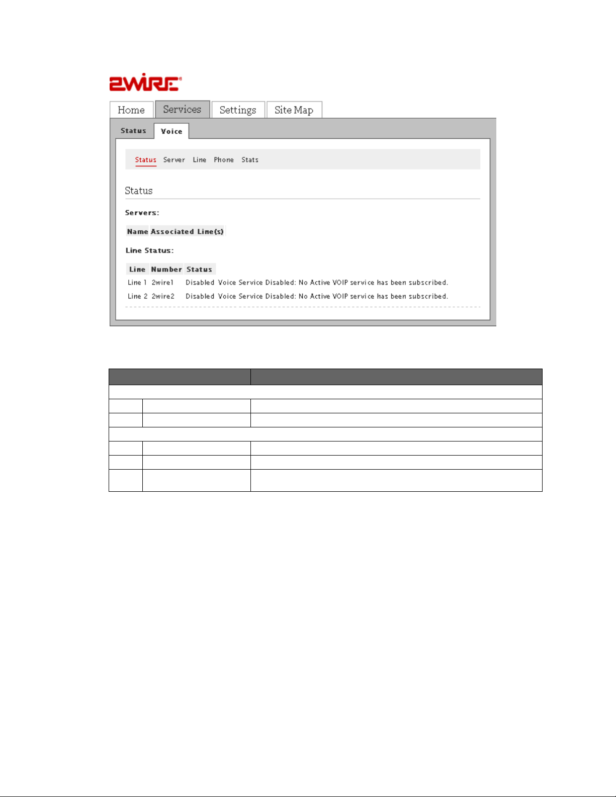
Viewing Status
This topic provides information about the Status page under the Voice Tab. You can view the status
of your phone lines and servers on this page.
To view the server and line status, navigate to Services > Voice > Status. The Status page
appears.
19
Page 28
HomePortal 3801HGV Gateway User Guide Configuring Voice-Based Services
You can view the following information on this page:
Param eter Description
Servers
Name Displays the name of the configured SIP server.
Associated Line Displays the phone lines associated with the SIP server.
Line Status
Line Displays the name of the configured line.
Number Displays the phone number of the configured line.
Status Displays the status of the configured line on the gateway. The status can be
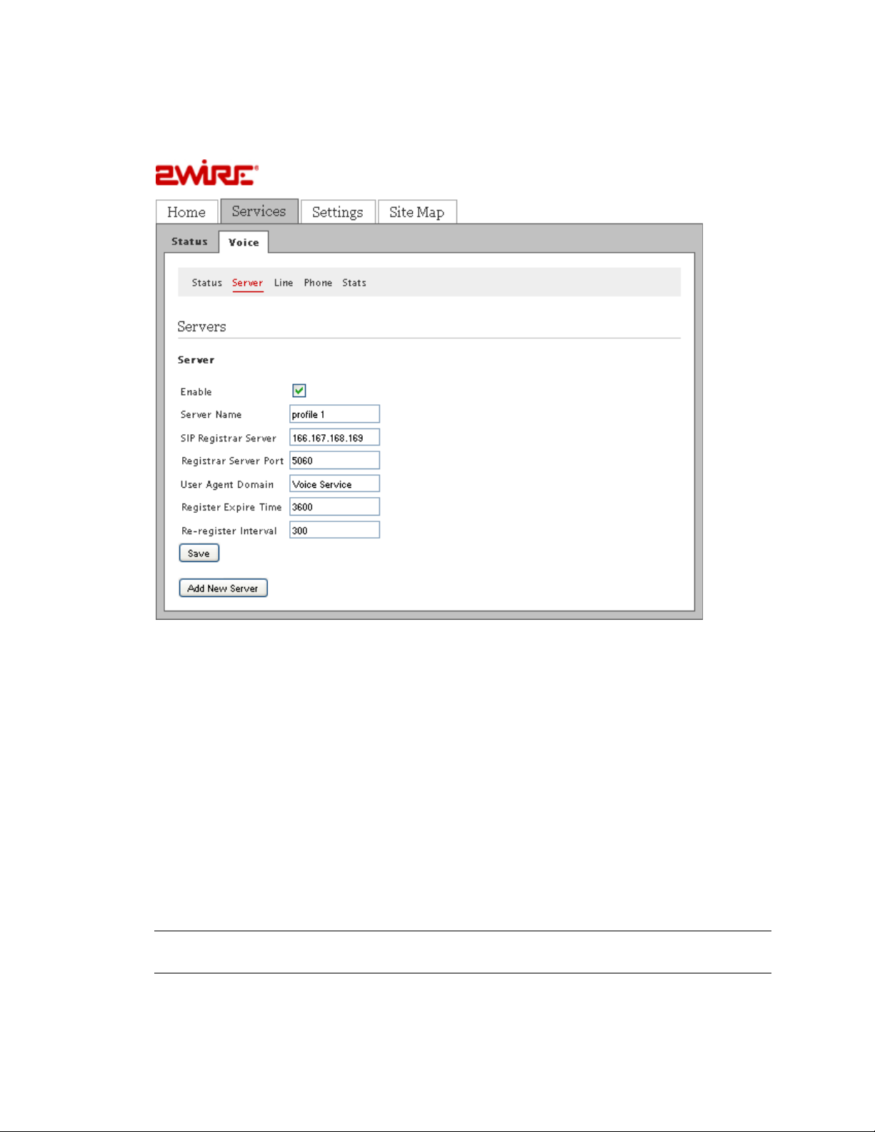
Configuring SIP Server
Objective
To configure the SIP server.
The SIP server provides a location service which registers one or more IP addresses to identify
certain names or resources on the Internet.
Your service provider gives you all the information required to configure the SIP server.
Registering, Enabled, or Disabled.
Configuring SIP Server 20
Page 29
HomePortal 3801HGV Gateway User Guide Configuring Voice-Based Services
Steps
1. Navigate to Services > Voice > Server. The Server page appears.
2. Select the Enable check box.
3. Type in a name for the server in the Server Name text box.
4. Enter the server name in the SIP Registrar Server Name text box. This can be an IP
address or a name provided by the service provider.
5. Enter the server port in the Registrar Server Port text box. The port number will be
provided by the service provider. The default port is 5060.
6. Enter the domain name in the User Agent Domain text box. This will be provided by the
service provider.
7. Enter the expire time in the Register Expire Time text box. This will be provided by the
service provider.
8. Enter the re-register interval time in the corresponding text box. This will be provided by the
service provider.
9. Click Save.
Note If your service provider has multiple SIP servers, you may need to configure additional
servers on this page. You can do this by clicking the Add New Server button.
Configuring SIP Server 21
Page 30
HomePortal 3801HGV Gateway User Guide Configuring Voice-Based Services
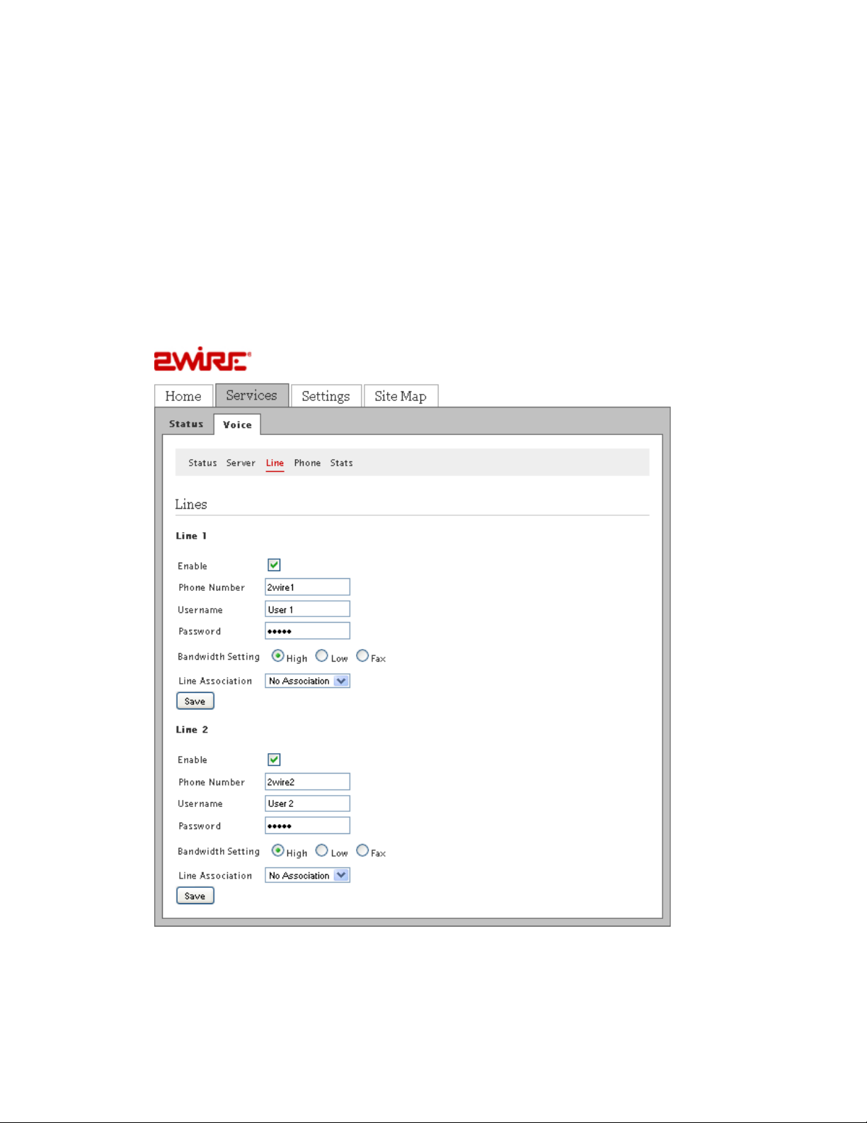
Configuring Phone Lines
Objective
To configure the phone lines.
You can configure your telephone number on this page. You can confgure 2 telephone lines at a
time in the HomePortal 3801HGV gateway. You can also configure a user name and password for
your account to prevent unauthorized access.
Steps
1. Navigate to Services > Voice > Line. The Line page appears.
2. Select the Enable check box in the Line 1 section. This activates the line for use.
Configuring Phone Lines 22
Page 31

HomePortal 3801HGV Gateway User Guide Configuring Voice-Based Services
3. Enter the phone number, user name, and the password in corresponding text boxes. This
will be given by the service provider.
4. Select the appropriate bandwidth setting as directed by the service provider.
5. Select the appropriate server to associate with the line in the Line Association drop-down
list box.
6. Click Save.
7. Configure the second phone line (if present) in the Line 2 section, and click Save.
Configuring Phones
Objective
To configure phones.
NOTE TO REVIEWER: Why do we need to configure phones separately from lines? Do we need
different types of phones for VoIP? Do we set up the physical phones in this section?
Configuring Phones 23
Page 32

HomePortal 3801HGV Gateway User Guide Configuring Voice-Based Services
Steps
1. Navigate to Services >Voice > Phone. The Phone page appears.
2. Enter the location of the phone in the corresponding text box in the Phone: Phone 1
section.
3. Select a line that you have configured in the Association drop-down list box.
4. Select the Service Outage check box if <insert info here>.
NOTE TO REVIEWER: Need info about the Service Outage check box.
5. Click Save.
6. Configure the second phone (if present) in the Phone: Phone 2 section, and click Save.
Note You will get all information regarding the location, association, and service outage for your
phone from the service provider.
Viewing External Line Statistics
To view call statistics, navigate to Services > Voice > Stats. The Stats page appears.
Viewing External Line Statistics 24
Page 33

HomePortal 3801HGV Gateway User Guide Configuring Voice-Based Services
To reset information about each configured line on this page, scroll down and click the Reset
button at the end of the information for that particular line.
You can view the following information on this page:
Param eter
Line 1 Displays status information about the phone line in use, as well as its current
Registration Status Displays registration information about the phone line in use.
Call Summary
Current Call Displays call summaries for the current call.
Last Completed Call Displays call summaries for the for your last completed call.
Cumulative Since Last Reset Displays collective call information since you last reset the page.
Call Statistics
Current incoming calls Displays complete call statistics of the current incoming call(s).
Current outgoing calls Displays complete call statistics of the current outgoing call(s).
Last incoming call Displays complete call statistics of the last incoming call.
Last outgoing call Displays complete call statistics of the last outgoing call.
Viewing External Line Statistics 25
Description
state.
Page 34

HomePortal 3801HGV Gateway User Guide Configuring Voice-Based Services
All incoming calls Displays complete call statistics of all incoming calls.
All outgoing calls Displays complete call statistics of all incoming calls.
See Also
Viewing Subscribed Services Status on page 17
Troubleshooting 3801HGV Gateway on page 109
Viewing External Line Statistics 26
Page 35

CHAPTER 7
Setting Up System Information
This chapter provides information about the tasks you can perform in the System Info tab.
Following are the links under the System Info tab, and associated tasks:
• Status
• Viewing System Information on page 27
• Password
• Setting Up System Password on page 29
• Date & Time
• Configuring Date and Time on page 30
• Event Notification
• Enabling Event Notifications on page 32
Viewing System Information
View your system information at a glance. Find details pertaining to your system including the
manufacturer name, model and serial number, and hardware and software versions. To view the
system information, navigate to Settings > System Info > Status. The Status page appears.
27
Page 36

HomePortal 3801HGV Gateway User Guide Setting Up System Information
You can view the following information on the Status page:
Param eter Description
Manufacturer Name of the gateway manufacturer.
Model Model number of the gateway.
Serial Number Serial number of the gateway. The serial number is also printed on the
Hardware Version Hardware version number of the gateway.
Software Version Version number of the software used for the gateway.
Key Code Key code of the gateway.
First Use Date Date when the gateway was powered on for the first time out of factory.
Cureent Date and Time Your current date and time.
Time Since Last Boot Time elapsed since you last booted the system.
DSL Modem Hardware version of the DSL modem.
System Password Displays Default if you use the default system for your system.
gateway.
Displays Custom if you have createad your own password for your system.
Displays None if you have not enabled password protection for your system.
Viewing System Information 28
Page 37

HomePortal 3801HGV Gateway User Guide Setting Up System Information
Setting Up System Password
Objective
To set up the system password.
This task allows you to set up a password for your system in order to protect it against
unauthorized access. You can either set up the default system password, or create your own
password.
Steps
1. Navigate to Settings > System Info > Password. The Password page appears.
2. You can perform one of the following tasks:
• Set the default system password. The default system password is displayed on the
side of the gateway device
• Create your own system password
Setting Default System Password
To set the default system password:
1. Select the Enable Password Protection box.
2. Click Use Default System password (printed on the side of the gateway).
The following figure shows the default password printed on the side of the gateway device.
Setting Up System Password 29
Page 38

HomePortal 3801HGV Gateway User Guide Setting Up System Information
Creating Your System Password
To create your own system password:
1. Select the Enable Password Protection box.
2. Click Create or Edit a Custom Password.
3. Enter a password in the Enter New Password text box. The password is case-sensitive,
and can contain up to 31 alpha-numeric characters with no spaces.
4. Enter the same password in the Confirm New Password text box.
5. Enter a hint in the Enter a Password Hint text box. A password hint can be a word, a
phrase, or a question that can help you in case you forget your password.
Note Although not required, it is strongly recommended that you enter a hint to act as a
reminder.
6. Click Save.
Configuring Date and Time
Objective
To configure the date and time of the system.
This task allows you to configure the correct date and time for your system. You can either
automatically set up the date and time, or configure it manually.
Configuring Date and Time 30
Page 39

HomePortal 3801HGV Gateway User Guide Setting Up System Information
Automatically Setting up Date and Time
To automatically set up date and time:
1. Navigate to Settings > System Info > Date & Time. The Date & Time page appears.
2. Select your time zone in the Current Time Settings area.
3. Click Save.
Note Do not forget to select the Daylight Savings Time check box in the Time Configuration
area if Daylight Savings Time is observed in your state.
Configuring Date and Time 31
Page 40

HomePortal 3801HGV Gateway User Guide Setting Up System Information
Manually Configuring Date and Time
To manually configure the date and time:
1. Navigate to Settings > System Info > Date & Time. The Time Configuration section
appears.
2. Select the Override automatic time configuration box in the Time Configuration section.
3. Set the time in the corresponding space in the hh:mm:ss format.
4. Set the date in the corresponding space in the yyyy/mm/dd format.
5. Select the Daylight Savings Tim check box.
6. Click Save.
Note When you configure the date and time manually, do not forget to select the Override
automatic time configuration check box.
Enabling Event Notifications
Objective:
To view notifications of service impacting events.
This task allows you to eable/disable event notifications. Enabling event notifications assists you
in detecting any service-impacting conditions that may need repair. After enabling event
notifications, the system automatically notifies you of the service-impacting conditions.
Enabling Event Notifications 32
Page 41

HomePortal 3801HGV Gateway User Guide Setting Up System Information
Enabling Notifications
To enable notifications:
1. Navigate to Settings > System Info > Event Notifications. The Event Notifications page
appears.
2. Select the Broadband Status Notification and/or Router-Behind-Router Detection check
boxes.
3. Click Save.
Note To enable router-behind-router detection, make sure that DHCP and NAT are enabled, and
the gateways are not in bridge mode.
Disabling Notifications
To disable notifications:
1. On the Event Notifications page, clear the Broadband Status Notification and/or RouterBehind-Router Detection check boxes.
2. Click Save.
See Also
Using Diagnostics Features on page 93
Troubleshooting 3801HGV Gateway on page 109
Enabling Event Notifications 33
Page 42

CHAPTER 8
Configuring Broadband Settings
This chapter provides information about the tasks you can perform in the Broadband tab. Following
are the links under the Broadband tab, and associated tasks:
• Status
• Viewing Broadband Status on page 34
• Link Configuration
• Configuring Bridge Mode on page 40
• Routing
• Adding Static Routes on page 42
• Multicast
• Configuring IP Multicast Sessions on page 43
• Viewing Multicast Statistics on page 44
•DNS Resolution
• Resolving Domain Name on page 47
Viewing Broadband Status
This task lets you view the connectivity status, Internet connection details, modem type, and traffic
statistics. You can also reset the page to view up-to-date information.
Note Broadband and Service LEDs must be solid green on the front panel of the device. Also,
ensure that the user interface is accessible.
To view broadband status, navigate to Settings > Broadband > Status. The Status page appears.
The following figure displays the Summary Status section of the Status page.
34
Page 43

HomePortal 3801HGV Gateway User Guide Configuring Broadband Settings
Refer to the following table for description of the Summary Status parameters listed on the Status
page:
Param eter Description
Internet Status of the Internet Connection. This displays Connected when the ISP
DSL Link Status of the DSL connection. This displays Connected when the DSL port of
acitvates your Internet connection.
the gateway is connected to the telephone jack. Ensure that your service
provider activates the VDSL connection.
The following figure displays the Internet Details section of the Status page.
Viewing Broadband Status 35
Page 44

HomePortal 3801HGV Gateway User Guide Configuring Broadband Settings
Refer to the following table for description of the Internet Details parameters listed on the status
page:
Param eter Description
Broadband Link Type Type of broadband connection.
Connection Type Identifies the method by which the gateway connects to the
Internet Service Provider (ISP). The methods can be:
• PPPoE
• PPPoA
•Direct IP
User Name User credentials to connect with your ISP. Your user name was either assigned
Current Internet Connection
IP Address IP address assigned by the ISP to the gateway for connecting to the Internet.
Subnet Mask Used in conjunction with your Internet address.
Default Gateway Default gateway is a server that assigns an IP address to your gateway for
Primary DNS IP address of the primary DNS server that the gateway uses for DNS name
Secondary DNS Used as a backup if the Primary DNS fails to respond.
Host Name Host name is a label that is configured on the gateway.
Domain Domain associates your gateway with your ISP on the broadband link.
MAC Address MAC address of the gateway.
MTU Maximum Transmission Unit is the maximum size of packets that are
PPPoE Access
Concentrator
PPPoE Service Type of PPPoE service being used.
to you or configured by you during the installation process. The correct user
name is required to successfully connect to the Internet.
accessing the Internet.
resolution. DNS allows Internet users to specify a name (domain name) to
reach a Web page (for example, www.domainname.com) instead of its Internet
address (for example, 111.222.111.222). When you enter the name of a Web
location (URL), the DNS looks up the name and resolves it to the Internet
address of the Web page.
communicated on your ISP network.
PPPoE server name.
Viewing Broadband Status 36
Page 45

HomePortal 3801HGV Gateway User Guide Configuring Broadband Settings
The following figure displays the DSL Details section of the Status page.
Refer to the following table for description of the DSL Details parameters listed on the status page:
Param eter Description
Modem Type Displays modem type: either built-in VDSL modem or external broadband
Connection Type Method by which the gateway connects to the ISP. The method can be:
DSL Line (Wire Pair) Line 1 (inner pair), Line 2 (outer pair), or searching for DSL signal. During
Current DSL Connection
modem through Ethernet.
•Direct IP
• PPPoE
installation, the gateway auto-detects whether the DSL signal is on line 1 or
line 2.
Viewing Broadband Status 37
Page 46

HomePortal 3801HGV Gateway User Guide Configuring Broadband Settings
Param eter Description
Rate Upload and download speeds in kilobytes per second.
Max Rate Maximum speed attained while uploading and downloading the data in
Noise Margin Current downstream and upstream noise margin in dB.
Attenuation Current downstream and upstream DSL attenuation in dB.
Output Power Current downstream and upstream DSL transmit and receive power in dB.
Protocol Protocol used to communicate between your gateway and your ISP.
Channel Setting in this field is determined by your ISP’s DSLAM equipment. Values are
DSLAM Vendor
Information
Rate Cap Configured DSL service downstream speed.
Attenuation @ 300kHz Measurement of the decrease in downstream signal strength in kilobytes per
Required Impulse Noise
Protection
Uncanceled Echo Measurement of the uncancelled echo relative to the background noise on the
VCXO Frequency Offset Indicates the difference of crystal frequency in parts per million (ppm) on the
Final Receive Gain Indicates the current receive gain setting (in dB), which will depend on the
Excessive Impulse Noise Indicates to what degree impulse noise is present on the line.
kilobytes per second.
Fast or Interleaved.
Lists information about the DSLAM, including country, DSLAM vendor, and
specifics.
second.
Measurement of how much impulse noise can be mitigated. Dependent on
the current line configuration.
line. This is an indication of how much the uncancelled echo is affecting DSL
performance, rather than an absolute measurement of the uncancelled echo.
ports of the gateway and the DSLAM.
length of the DSL line.
The following figure displays the Traffic Statistics section of the Status page.
Refer to the following table for description of the Traffic Statistics parameters listed on the status
page:
Param eter Description
Transmit Cumulative number of bytes, IP packets, errors, and percentage of errors
Recieve Cumulative number of bytes, IP packets, errors, and percentage of errors
transmitted.
received.
The following figure displays the DSL Link Errors section of the Status page.
Viewing Broadband Status 38
Page 47

HomePortal 3801HGV Gateway User Guide Configuring Broadband Settings
Refer to the following table for description of the DSL Link Errors parameters listed on the status
page:
Param eter Description
Link Retrains Number of DSL retrains since the gateway was last restarted, and the time
DSL Training Errors Number of failed DSL retrains since the gateway was last restarted, and the
Training Timeouts Number of timeouts waiting for response from ATU-C since the 2Wire gateway
Loss of Framing Failures Number of DSL loss of framing failures since the gateway was last restarted,
Loss of Signal Failures Number of DSL loss of signal failures since the 2Wire gateway was last
Loss of Power Failures Number of DSL loss of power indications from the ATU-C since the gateway
Loss of Margin Failures Number of DSL loss-of-margin failures at current data rate since the 2Wire
Cum. Sec. w/Impulsive Events Number of impulsively errored seconds since the gateway was last restarted,
Cum. Seconds w/Errors Number of cumulative errored seconds since the gateway was last restarted,
Cum. Sec. w/Severe Errors Number of severely errored seconds since the gateway was last restarted,
Corrected Blocks Number of corrected DSL superframes that have data errors detected during
elapsed since the last retrain.
elapsed time since the last failed retrain.
was last restarted, and the elapsed time since the last initialization timeout.
and the elapsed time since the last line search initialization.
restarted, and the elapsed time since the last loss of signal failure.
was last restarted, and the elapsed time since the last loss of power
indication.
gateway was last restarted, and the elapsed time since the last loss of
margin failure.
and the elapsed time since the last impulsively errored second.
and the elapsed time since the last error.
and the elapsed time since the last severely errored second.
reception.
Viewing Broadband Status 39
Page 48

HomePortal 3801HGV Gateway User Guide Configuring Broadband Settings
Param eter Description
Uncorrectable Blocks Number of uncorrected DSL superframes that have data errors detected.
DSL Unavailable Seconds Number of times the ISP connection was established since the statistics were
last reset, and the elapsed time since the last establishment.
Resetting Statistics on Status Page
After rectifying the issues that are seen in different sections of the Status page, you must reset
this page to determine if the issue is resolved. To do this, click the Reset Statistics button at the
bottom of the Status page.
Configuring Bridge Mode
Objective
To configure bridge mode.
Bridge mode is used to configure devices on the LAN with a broadband IP. When the gateway is into
bridge mode you can use a supplementary network or a third party router to handle the traffic. The
gateway will only function as a direct connection to the phone line.
Note By default, the gateway is configured in the routing mode. When routing is disabled, the
NAT and the DHCP server are also disabled. Confirm with the ISP that the WAN protocol is
compatible with bridging mode.
Configuring Bridge Mode 40
Page 49

HomePortal 3801HGV Gateway User Guide Configuring Broadband Settings
Steps
1. Navigate to Settings > Broadband > Link Configuration. Configure the following section of
the Link Configuration page to enable the bridge mode and add supplementary networks:
2. Select the Use Broadband IPs on LAN check box. This enables bridge mode on the
gateway.
3. Enter the subnet mask address in the Specify usable subnet mask text box. You must
specify this address on the LAN devices or supplementary network devices while
configuring the subnet mask. The recommended subnet mask address is 255.255.255.0.
4. Select the Auto Firewall Open check box. This disables the firewall of the gateway. Make
sure that you select this option because the firewall must be disabled for the bridge mode
to function.
5. Select the Use the built-in system MAC address radio button from the System MAC
Address section to use the configured MAC address.
OR
Select the Override the built-in MAC address radio button from the System MAC Address
section, and mention a MAC address of your choice in the Specify MAC address text box.
6. Leave the Upstream MTU value as is. This is the maximum size allowed on packets that
are communicated between your network and your ISP.
7. Select the Add Additional Network check box to tail a router from the Local Ethernet port
located at the back panel of the gateway. This adds a secondary network to the broadband
WAN interface.
8. Enter the gateway address of the supplementary network device in the Router Address text
box. This is the gateway address of the secondary subnet.
Configuring Bridge Mode 41
Page 50

HomePortal 3801HGV Gateway User Guide Configuring Broadband Settings
9. Enter the Subnet Mask address in the text box. This is the router mask of the secondary
subnet.
10. Select the Auto Firewall Open check box to disable the firewall for all devices using
addresses from this subnet.
11. Clear the Routing check box to ensure that the gateway does not assign IP addresses to
LAN devices through DHCP.
12. Click Save.
The bridge mode is enabled on the gateway, and LAN devices are configured to take the Broadband
IP address. The service LED on the front panel of the device remains off when the gateway is in
bridge mode. The supplementary network represented by the router is tailed to the gateway.
Adding Static Routes
Objective
To add static routes.
This task lets you manually configure static routes for specifying the transmission path that the
data must follow between devices outside the gateway network.
Adding Static Routes 42
Page 51

HomePortal 3801HGV Gateway User Guide Configuring Broadband Settings
Steps
1. Navigate to Settings > Broadband > Routing. The Static Routes page appears.
2. Enter the IP address of the destination network in the Subnet IP text box.
3. Enter the subnet mask of the destination network in the Subnet Mask text box.
4. Enter the gateway address of the destination network in the Gateway IP text box.
5. Click Add To List.
The Static Route List section displays the new Subnet IP, Subnet Mast, Gateway IP, and Interface
name.
Configuring IP Multicast Sessions
Objective
To configure IP multicast sessions.
Configuring IP Multicast Sessions 43
Page 52

HomePortal 3801HGV Gateway User Guide Configuring Broadband Settings
When information is broadcast on a network, information packets are delivered to all segments on
the LAN. This degrades network performance. IP multicasting is a method of forwarding information
to a group of interested receivers.
Internet Group Management Protocol (IGMP) is used to manage IP Multicast sessions. IGMP
provides a means to automatically control and limit the flow of multicast traffic throughout your
network with the use of special multicast queriers and hosts.
Steps
1. Navigate to Settings > Broadband > Multicast. The Multicast page appears.
2. Select the IGMP Proxy check box to enable the feature. When IGMP Proxy is enabled, the
gateway issues IGMP host messages on behalf of the hosts discovered through standard
IGMP interfaces. In other words, the gateway acts as a proxy for its hosts.
3. Select the IGMP Snooping check box to enable the feature. When IGMP Snooping is
enabled, the gateway analyzes all IGMP packets and selectively forwards multicast traffic
only to those ports where particular IP Multicast streams are accepted.
4. Select the IGMP Query Response Interval check box to enable the feature. When IGMP
Query Response Interval is enabled, you control the number of IGMP messages allowed on
the subnet during the specified duration.
5. Click Save.
Viewing Multicast Statistics
To view multicast statistics, navigate to Settings > Broadband > Multicast. The Multicast page
appears.
Viewing Multicast Statistics 44
Page 53

HomePortal 3801HGV Gateway User Guide Configuring Broadband Settings
Refer to the following table to understand the IGMP parameters listed on the multicast page:
IGMP Parameter Description
IGMP Interface Name Name of the interface for which statistics are being reported.
IGMP Enable Query Displays whether the interface has IGMP querying enabled or disabled.
IGMP Fast Update Displays whether the interface has IGMP fast update enabled or disabled.
IGMP Version Displays the IGMP version.
Viewing Multicast Statistics 45
Page 54

HomePortal 3801HGV Gateway User Guide Configuring Broadband Settings
IGMP Parameter Description
IGMP Robustness Time interval that the gateway waits for a report in response to a group-
IGMP Query Interval Time interval at which the gateway sends membership queries when it is the
IGMP Query Response Interval Time interval that the gateway waits for a report in response to a general
IGMP Group Membership Interval Timeout period for group membership. If no report is received for these
IGMP Startup Query Interval Amount of time in seconds between successive General Query messages
IGMP Startup Query Count Number of general query messages sent at startup.
IGMP Last Member Query Interval Time interval that the gateway waits for a report in response to a group-
IGMP Last Member Query Count Number of Group-Specific Query messages sent before the gateway assumes
IGMP Maximum Host Groups Maximum number of host group members.
IGMP Maximum Sources Maximum number of source-specific join and leave messages.
IGMP Query Count Number of membership queries sent and received.
IGMP Framing Errors Number of frame errors related to ARP, IP, and RARP.
IGMP Invalid Type Number of times gateway received Invalid IGMP Type message.
IGMP Allocation Failure Number of times gateway received Allocation Failure messages, such as
IGMP Host Group Exceeded Number of times host groups have exceeded in the message.
IGMP Sources Exceeded Number of times source addresses have exceeded in the message.
IGMP Other Querier Timeout period for group membership. If no report is received for these
IGMP Membership Entries Number of group membership entries on an interface.
IGMP Total Received Messages Number of total messages received.
IGMP Received Short Messages Number of short messages received.
IGMP Bad Checksum Messages Number of messages received with a bad IP checksum.
IGMP Inquiry Messages Number of membership inquiry messages issued by the gateway.
IGMP Bad Inquiry Messages Number of membership inquiry messages issued by the gateway that were not
IGMP Report Messages Number of report messages sent by the host to the members of the querying
IGMP Bad Report Messages Number of report messages that were sent by the host but were not realized
IGMP Own Group Report
Messages
IGMP Transmitted Reports Total number of IGMP reports transmitted by the gateway.
IGMP Group Entries Total number of group entries on an interface.
IGMP Cache Entries Total number of cache entries on an interface.
IGMP Group Interface Name Interface name of the IGMP group.
IGMP Group Interface Address IP address of the IGMP group interface.
IGMP Group Interface Reference
Count
specific query.
querier.
query.
groups before the timeout expires, the group membership is removed.
sent by a querier during startup.
specific query.
that there are no members of the host group being queried on this interface.
memory allocation failure, IP address allocation failure, and so on.
groups before the timeout expires, the group membership is removed.
realized by this protocol.
group.
by the members of that group.
Number of report messages sent by the host to the members of the same
group.
Number of processes belonging to the IGMP group interface.
Viewing Multicast Statistics 46
Page 55

HomePortal 3801HGV Gateway User Guide Configuring Broadband Settings
Resolving Domain Name
Objective
To manually add a domain name for resolving the IP address of the networked devices.
This task allows you to name network devices (such as printers or Web servers), so that they can
be easily accessed by other users on the network.
Note Confirm that the domain name is not in use.
Resolving Domain Name 47
Page 56

HomePortal 3801HGV Gateway User Guide Configuring Broadband Settings
Steps
1. Navigate to Settings > Broadband > DNS Resolution. The Domain Name Server
Resolution page appears.
2. Enter a name for the network device in the DNS Name text box.
3. Enter the IP address of the network device in the IP Address text box.
4. Click Add To Name Resolution Table. The Name Resolution Table section displays the
newly added and existing DNS name, IP address, and Entry type.
See Also
Configuring LAN Devices on page 50
Configuring Firewall Settings on page 72
Resolving Domain Name 48
Page 57

HomePortal 3801HGV Gateway User Guide Configuring Broadband Settings
Using Diagnostics Features on page 93
Troubleshooting 3801HGV Gateway on page 109
Resolving Domain Name 49
Page 58

CHAPTER 9
Configuring LAN Devices
NOTE TO REVIEWER: [JIRA 1515: ...Unable to determine the steps to set up multiple SSIDs and
associated information on the UI of 3801HGV.].
Please provide the necessary info to document this. How do we configure multiple SSIDs through
the UI?
This chapter provides information about the tasks you can perform in the LAN tab. Following are the
links under the LAN tab, and associated tasks:
• Status
• Viewing LAN Status on page 51
• Wireless
• Setting Up Wireless Network on page 53
• Securing the Wireless Network Using Encryption Key on page 55
• Securing the Wireless Network Using MAC Filtering on page 57
• Configuring Advance Wireless Settings on page 61
• Configuring Wi-Fi Protected Setup on page 62
• Wired Interfaces
• Configuring Local Ethernet Ports on page 64
• Configuring HomePNA 3.1 on page 65
• Viewing HomePNA Status on page 66
•DHCP
• Configuring DHCP on page 66
• IP Address Allocation
• Allocating IP Addresses on page 69
50
Page 59

HomePortal 3801HGV Gateway User Guide Configuring LAN Devices
Viewing LAN Status
To view the LAN status page, navigate to Settings > LAN > Status. The Status page appears.
The following figure displays the Private Network section of the Status page.
Refer to the following table to understand the Private Network parameters listed on the Status
page:
Param eter Description
Router/Gateway Address IP address allocated to the gateway.
Subnet Mask Subnet mask allocated to the gateway.
Private Network DHCP Info
Range Range of IP addresses available on the network.
Allocated Number of IP addresses allocated on the network.
Remaining Number of IP addresses remaining on the network.
Timeout Time in minutes before the DHCP lease must be renewed.
Viewing LAN Status 51
Page 60

HomePortal 3801HGV Gateway User Guide Configuring LAN Devices
The following figure displays the Interfaces section of the Status page.
Refer to the following table to understand the Interface parameters listed on the Status page:
Param eter Description
Ethernet Displays whether the Ethernet interface is enabled or disabled. Also displays
Wireless Displays whether the wireless interface is enabled or disabled. Also displays
HomePNA1 Displays whether the HPNA interface is enabled or disabled. Also displays
the number of active and inactive Ethernet devices on the network.
the number of active and inactive wireless devices on the network.
whether the HPNA interface is active or inactive on the network.
The following figure displays the Wireless section of the Status page.
Refer to the following table to understand the Wireless parameters listed on the Status page:
Param eter Description
Wireless Channel Radio frequency band that the access point uses for your wireless network.
Wireless Power Level Power level for your wireless connection.
SSID Name Name assigned to your wireless network. The default is 2WIREXXX, where XXX
Status Displays whether the wireless connection is enabled or disabled.
SSID Broadcast Displays whether broadcasting of SSID is enabled or disabled.
Security Security method used to ensure that authorized users are accessing the
Viewing LAN Status 52
represents the last three digits of the serial number of your gateway (for
example, 2WIRE008).
wireless network.
Page 61

HomePortal 3801HGV Gateway User Guide Configuring LAN Devices
The following figure displays the Devices section of the Status page.
Refer to the following table to hide inactive devices and clear the list of devices appearing on the
Status page:
Step Result
Click Hide Inactive Devices. Devices that are no longer on the local network will be hidden from the
Click Clear List. Devices that are no longer active on the local network are cleared from the
Devices list on this page and under Home Network Devices on the Home
page.
Devices list on this page and under Home Network Devices on the Home
page.
Setting Up Wireless Network
Objective
To setup your wireless network.
This configuration determines the wireless settings used to access the wireless interface of the
gateway.
Steps
1. Navigate to Settings > LAN > Wireless. The Wireless page appears.
Setting Up Wireless Network 53
Page 62

HomePortal 3801HGV Gateway User Guide Configuring LAN Devices
Setting Up Wireless Network 54
Page 63

HomePortal 3801HGV Gateway User Guide Configuring LAN Devices
2. Enable the wireless connection by selecting the Enable Wireless Interface check box.
3. Enter a name assigned to your wireless network in the Network Name (SSID) text box. The
default is 2WIREXXX, where XXX represents the last three digits of your 2Wire gateway
serial number (for example, 2WIRE008). This name appears next to the Wireless icon on
the Home page.
Note The HomePortal 3801HGV gateway can support up to 4 SSIDs. It can support upto 4
wireless devices at a time.
4. Enable the broadcast of the SSID over the wireless network by selecting the SSID
Broadcast check box. This implies that the broadcasted SSID is visible to the users who
are scanning to connect to a wireless network.
Note You can disable the broadcast of the SSID by clearing the SSID Broadcast check box.
When you disable SSID Broadcast, the LAN client cannot scan and connect to your
wireless network. You have to manually add a wireless profile in the LAN client to connect
to the wireless network instead of selecting the SSID name from a typical scan list.
5. Select a wireless channel (radio frequency band) from the corresponding drop-down list
box. This is the access point used for your wireless network. Wireless clients or wireless
adapter cards auto-detect the channels to use. If you are having problems with your
wireless network, it could be due to radio interference. You can change the wireless
channel to see if interference is reduced on a different channel. It is best to select Auto,
because a channel is automatically selected to minimize interference.
6. Click Save. This ensures that the configured wireless setting is saved.
Securing the Wireless Network Using Encryption Key
Objective
To secure your wireless network using the encryption key.
Encrypted security setting makes it difficult for unauthorized users to access your network. It is
good practice to customize an encryption key for wireless communication. When the key is defined,
each wireless client must have it to connect to your wireless network.
Securing the Wireless Network Using Encryption Key 55
Page 64

HomePortal 3801HGV Gateway User Guide Configuring LAN Devices
Steps
1. Navigate to Settings > LAN > Wireless. The Wireless page to configure the Security
settings appears.
2. Enable or disable the wireless security by selecting or clearing the Wireless Security check
box. Wireless security is enabled as a default setting.
3. Select an authentication setting from the Authentication Type drop-down list box. Check
the capabilities of the wireless clients that will be accessing this network and find a secure
protocol by referring to the following table:
Authentication Type Description
WEP-Open The Wireless Encryption Protocol (WEP) is an older security protocol that allows
WEP-Shared Similar to the WEP-Open setting, do not select this setting unless there is a
WPA-PSK (TKIP) This setting provides good security and works with most newer wireless clients.
WPA-PSK (TKIP) and
WPA2-PSK (AES)
WPA2-PSK (AES) This setting requires that wireless clients use only WPA2-PSK to access your
any wireless clients within the radio range to access your network without an
encryption key. This setting provides the least level of security. For security
reasons, do not select this setting unless there is a compatibility issue with an
older wireless client. For added protection, set an encryption key on your AP and
enter the same key into your other wireless clients.
compatibility issue with an older wireless client. Unlike the WEP-Open setting,
the WEP-Shared setting prevents open access by any wireless client; therefore,
it is more secure than the WEP-Open setting. For added protection, set an
encryption key on your AP and enter the same key into your other wireless
clients.
This setting requires an encryption key on the AP and the wireless client
configured to use Wi-Fi Protected Access – Pre-Shared Key (WPA-PSK) with the
same encryption key.
This setting allows a wireless client to use either WPA-PSK or WPA2-PSK to
access your network. An encryption key must be configured on the AP and the
same key must be entered on the wireless client.
networks. An encryption key must be configured on the AP and entered into the
wireless client. WPA2-PSK is currently the most secure Wi-Fi encryption protocol
but may not be available on many wireless clients.
4. Select the Use default encryption key printed on the System Label radio button to use the
encryption key that came with your gateway.
OR
Select the Set custom encryption key radio button to create a custom encryption key. You
can define a 64-bit or 128-bit encryption key. For 64-bit encryption, enter a 10-digit
hexadecimal number. For 128-bit encryption, enter a 26-digit hexadecimal number. A
Securing the Wireless Network Using Encryption Key 56
Page 65

HomePortal 3801HGV Gateway User Guide Configuring LAN Devices
hexadecimal number uses the characters 0-9, a-f, or A-F.
This security key will be used by all clients to access your wireless network.
5. Click Save. This ensures that the configured security setting is saved.
Securing the Wireless Network Using MAC Filtering
Objective
To secure your wireless network using the MAC filtering feature.
This feature enables you to block or allow wireless connection to all devices, or an individual device
based on the MAC address of the device. You allow only “known and trusted” devices to associate
with the wireless access point. MAC address filtering is disabled as a default setting. When
enabled, the wireless connection is granted only to the MAC addresses that are pre-configured in
the allowed device list.
Steps
1. Navigate to Settings > LAN > Wireless. The Wireless page appears.
2. In the MAC Filtering section, click Edit Blocked/Allowed Device List link. The Wireless
MAC Filtering page appears.
Securing the Wireless Network Using MAC Filtering 57
Page 66

HomePortal 3801HGV Gateway User Guide Configuring LAN Devices
3. Enable or disable the MAC filtering by selecting or clearing the Enable MAC Filtering check
box. MAC filtering is disabled as a default setting. Disabling MAC address filtering allows
all the wireless clients to access the device.
4. Click Save. This ensures that the configured MAC filtering setting is saved.
5. Allow block devices to access wireless interface based on MAC filtering feature by
configuring the Select Devices to be Allowed or Blocked pane.
Allowing MAC Addresses
Objective
This feature enables you allow wireless connection to all devices, or an individual device based on
the MAC address of the device.
Securing the Wireless Network Using MAC Filtering 58
Page 67

HomePortal 3801HGV Gateway User Guide Configuring LAN Devices
Steps
1. Navigate to Settings > LAN > Wireless. The Wireless page to configure the MAC filtering
settings appears.
2. Add the MAC address of the device in the Enter MAC address text box.
3. Click Add To List. This populates the MAC address in the Allowed Devices pane.
Blocking MAC Addresses
Objective
This feature block wireless connection to all devices, or an individual device based on the MAC
address of the device.
Steps
1. Navigate to Settings > LAN > Wireless. The Wireless page appears.
2. In the MAC Filtering section, click Edit Blocked/Allowed Device List link. The Wireless
MAC Filtering page appears.
3. Select the device you want to block from the Allowed Devices pane.
Note To select multiple addresses, hold down the [Shift] or [Ctrl] keys while making your
selections. Using the [Shift] key lets you make your selections in a contiguous order, while
the [Ctrl] key selects the groups in a random order.
4. Click >>. This polulates the MAC address in the Blocked Devices pane.
Securing the Wireless Network Using MAC Filtering 59
Page 68

HomePortal 3801HGV Gateway User Guide Configuring LAN Devices
Refreshing the List of Devices
Objective
This feature enables you to refresh the list of devices while allowing or blocking wireless connection
based on the MAC Addresses of the devices.
Steps
1. Navigate to Settings > LAN > Wireless. The Wireless page appears.
2. In the MAC Filtering section, click Edit Blocked/Allowed Device List link. The Wireless
MAC Filtering page appears.
3. Click Rescan For Devices to refresh the list of devices viewed in Allowed Devices and
Blocked Devices panes.
Deleting the Devices
Objective
To delete a configured device. This feature enables you to delete devices from the list of allowed or
blocked devices.
Steps
1. Navigate to Settings > LAN > Wireless. The Wireless page appears.
2. In the MAC Filtering section, click Edit Blocked/Allowed Device List link. The Wireless
MAC Filtering page appears.
3. Select the device from Allowed Devices or Blocked Devices pane.
4. Click Delete.
5. Click Save to retain the configuration changes.
After any configuration change you have made on this user interface, a page opens confirming that
the configuration is changed.
Securing the Wireless Network Using MAC Filtering 60
Page 69

HomePortal 3801HGV Gateway User Guide Configuring LAN Devices
Configuring Advance Wireless Settings
Objective
To configure advance wireless settings.
This allows you to further optimize wireless settings for better performance.
Note It is recommended that you leave the default settings as is; however, if you are
experiencing connection or performance difficulties, altering these settings may improve
performance.
Steps
1. Navigate to Settings > LAN > Wireless. The Wireless page to configure the Advanced
Settings appears.
2. Select the power level for your wireless connection from the Power Setting drop-down list.
The configured power level is the actual transmitted radio power at the access point. The
default list is from 1 to 4. Following table provides the output power levels for 802.11b and
802.11g types of wireless modes:
Power Settings Radio Output Power
802.11b (mW) 802.11g (mW)
1 (maximum) 50 30
225 15
312 8
46 4
3. Select the Wireless Mode from the drop-down list. This allows you to force the gateway to
use 802.11b/g, 802.11b-only, or 802.11g-only modes of operation. Check the wireless
mode supported by the wireless adapter before configuring this option.
4. Enter the DTIM Period (seconds) in the text box. This Delivery Traffic Indication Message
(DTIM) value determines the interval at which the access point sends its broadcast traffic.
5. Select the Maximum Connection Rate from the drop-down list. This is the maximum rate
at which your wireless connection works. Select 1, 2, 5.5, 11, or 22 Mbps for 802.11bbased models and 1, 2, 5.5, 11, 6, 9, 12, 24, 36, 48, or 54 Mbps for 802.11b/g-based
models.
Configuring Advance Wireless Settings 61
Page 70

HomePortal 3801HGV Gateway User Guide Configuring LAN Devices
6. Click Save. This ensures that the advance wireless settings are saved.
Configuring Wi-Fi Protected Setup
Objective
To configure Wi-Fi protected setup (WPS).
This configuration simplifies the process of connecting any home device to the wireless network. As
an access point (AP), the gateway issues and revokes credentials to a network.
WPS supports both push button and PIN-based configuration methods. When WPS is enabled, the
gateway automatically detects the presence of a WPS-enabled client device. Both methods require
WPA or WPA2 security enabled and the predefined passphrase is provided to the WPS device.
Steps
1. Navigate to Settings > LAN > Wireless. The Wireless page appears.
2. In the Wi-Fi Protected Setup section, enable the WPS by selecting the Wi-Fi Protected
Setup check box.
Setting Up WPS through the PIN Method
To set up WPS through the PIN method:
1. Navigate to Settings > LAN > Wireless. The Wireless page appears.
2. In the Wi-Fi Protected Setup section, enable the WPS by selecting the Wi-Fi Protected
Setup check box.
3. Select PIN from the drop-down list.
Configuring Wi-Fi Protected Setup 62
Page 71

HomePortal 3801HGV Gateway User Guide Configuring LAN Devices
4. Enter a 4 or 8 digit PIN in Enter the PIN text box. The PIN method requires a 4- or 8-digit
PIN.
5. Click Set WPS. This saves the PIN configuration changes done for WPS.
Setting Up WPS through the Push Button Method
To set up WPS through the PIN method:
1. Navigate to Settings > LAN > Wireless. The Wireless page appears.
2. In the Wi-Fi Protected Setup section, enable the WPS by selecting the Wi-Fi Protected
Setup check box.
3. Select Push Button from the drop-down list.
4. Locate and push the WPS button found at the front panel of the device. The gateway
provides a push button on the front panel to enable the synchronization between the AP
and the client. You do not have to connect any devices to the gateway to enable it - simply
push the button on the gateway followed by pushing the button on the client device.
5. Click Set WPS. This saves the Push Button configuration changes done for WPS.
Configuring Wi-Fi Protected Setup 63
Page 72

HomePortal 3801HGV Gateway User Guide Configuring LAN Devices
Configuring Local Ethernet Ports
Objective
To configure local Ethernet ports.
This task lets you configure the local Ethernet ports to connect to network devices that support
speeds upto 10 Mbits (10BaseT/UTP) and 100 Mbits (100BaseTX), and require a unique setting.
By default, the Ethernet ports are pre-configured to auto-detect mode.
Steps
1. Navigate to Settings > LAN > Wired Interfaces. The Ethernet Switch page appears.
2. Enable or disable the local Ethernet networking by selecting or clearing the Ethernet
Networking check box.
3. Match the mode of the Local Ethernet port located at the back panel of the gateway with
the Ethernet port of the LAN client. Select one of the following options from the Port 1
Mode drop-down list:
• Auto-detect
• 100BaseTX Full-Duplex
• 100BaseTX Auto
• 10BaseT/UDP Full-Duplex
• 10BaseT/UDP Auto
4. Select the relevant modes for the remaining ports as mentioned in Step 3.
5. Click Save. This saves the configuration changes done to the Local Ethernet ports.
Configuring Local Ethernet Ports 64
Page 73

HomePortal 3801HGV Gateway User Guide Configuring LAN Devices
Configuring HomePNA 3.1
Objective
To configure Home Phoneline Networking Alliance (HPNA) on the Cable port.
This task lets you configure HPNA interface on the Cable port of the gateway.
Steps
1. Navigate to Settings > LAN > Wired Interfaces. The HPNA 3.1 (Coax) configuration page
appears.
2. Enable or disable HPNA by selecting or clearing the HomePNA Networking check box.
3. Select Coax or DSL from the Select Output Jack drop-down list. This is the type of gateway
port that you use to connect to the set top box. If you select Coax it implies that you are
using CABLE port. If you select DSL it implies that you are using DSL port.
NOTE TO REVIEWER: Unsure whether the user can actually use the DSL port to configure the HPNA
interface. The device has only one DSL port which is used to connect Internet. My understanding is
that the device must have an addition RJ-11 port to configure HPNA interface. Need inputs for the
same.
4. Select 493 or 340 from the Noise Margin drop-down list. This is the signal to noise ratio.
Signal quality is inversely proportional to noise margin.
5. Select 1063, 859, or 646 from the Per drop-down list.
NOTE TO REVIEWER: Unable to determine the purpose of this field. Need inputs for this field.
6. Enter the duration in seconds in the Collection Interval text box. This is the number of
seconds during which the counters for data are collected.
7. Click Save. This saves the HPNA configuration changes.
Configuring HomePNA 3.1 65
Page 74

HomePortal 3801HGV Gateway User Guide Configuring LAN Devices
Viewing HomePNA Status
To view HomePNA status page, navigate to Settings > LAN > Wired Interfaces. Click HomePNA
Status listed at the bottom of the wired interfaces page. The following page appears:
Refer to the following table to understand the HomePNA Network parameters listed on the status
page:
Param eter Description
Firmware Version Firmware version number.
Firmware Signature Firmware signature number.
HPNA Physical Link Displays whether the HPNA interface is enabled or disabled.
Network Mode Network mode of the HPNA interface.
Node ID Node ID of HPNA interface.
MTU Maximum Transmission Unit is the maximum size allowed on data packets,
MAC Address MAC address of the gateway.
Configuring DHCP
Objective
To configure Dynamic Host Configuration Protocol (DHCP) for setting up your private network. In this
task, we are listing the steps to configure the DHCP server.
DHCP allows dynamic allocation of network addresses. Your gateway can be both a DHCP client and
a DHCP server. When communicating with the local network devices, such as computers and
printers, your gateway functions as a DHCP server. However, while communicating with your ISP, the
gateway functions as a DHCP client.
that are communicated on HPNA network.
Viewing HomePNA Status 66
Page 75

HomePortal 3801HGV Gateway User Guide Configuring LAN Devices
By default, the gateway uses the 192.168.1.0/255.255.0.0 IP address range. You can select from
two additional IP address ranges, or configure the network settings manually. When you select
either of them, the LAN clients are assigned IP addresses within the specified range.
Note You should manually configure these settings ONLY if you thoroughly understand IP
internetworking. An incorrect configuration can cause unpredictable results.
Configuring DHCP 67
Page 76

HomePortal 3801HGV Gateway User Guide Configuring LAN Devices
Steps
1. Navigate to Settings > LAN > DHCP. The DHCP Configuration page appears.
2. Enable or disable the DHCP server by selecting or clearing the DHCP Server Enabled check
box.
3. Select a relevant radio button from DHCP Network Range, to use the default range of IP
addresses or configure the DHCP server manually. If you are using the default range of IP
address, continue to step 5. However, if you want a limited range of IP addresses, then go
to step 4.
Configuring DHCP 68
Page 77

HomePortal 3801HGV Gateway User Guide Configuring LAN Devices
Note 3801HGV supports four subnets simultaneously on the LAN. The 192.168.1.0 /
255.255.255.0 (default) is used as a private subnet by the end user. The 172.16.0.0 /
255.255.0.0 is used as the secondary subnet or public routed subnet by the end user. The
remaining options, 10.0.0.0 / 255.255.0.0 and Configure manually are held in reserve to
be configured and used by the service provider.
4. Select the Configure manually radio button for setting up a range IP addresses to be
assigned to LAN clients. To populate the text fields under this section, refer to the following
information:
a. Enter the IP address of your gateway (default is 192.168.1.254) used for all
communication on your local devices in the Router Address text box.
b. Enter the subnet mask (default is 255.255.255.0) used for all communication on your
local devices in the Subnet Mask text box.
c. Enter the first IP address in the DHCP address pool that you will be distributing over
the private network in the First DHCP Address text box.
d. Enter the last IP address in the DHCP address pool that you will be distributing over the
private network in the Last DHCP Address text box.
5. Enter a numerical value in the DHCP Lease Time text box. This value represents the
number of hours you can use the assigned IP address before the DHCP lease expires.
6. Select Private Network from the New Device DHCP Pool drop-down list for assigning IP
addresses to LAN clients from the private IP address pool. Select Public Network to
assign IP addresses to LAN clients from public IP address pool. Public network selection is
available only when bridge mode is enabled.
Note Change to the Public IP addressing only when used in conjunction with DMZplus or
secondary subnet functionality that allows you to have public IP addresses routed through
the device.
7. Click Save. This saves the DHCP configuration changes.
Allocating IP Addresses
Objective
To allocate specific IP addresses to devices that are running in the DHCP mode, and map devices
to particular static or private IP addresses.
For Internet public hosting of application or servers associated with static addresses, you can map
a device to a specific static IP address or to the next unassigned address from the public pool.
Allocating IP Addresses 69
Page 78

HomePortal 3801HGV Gateway User Guide Configuring LAN Devices
Steps
1. Navigate to Settings > LAN > IP Address Allocation. The Public-Private NAT Mappings
and Device IP Allocation page appears.
2. Navigate to the relevant device for changing the configuration to override the default DHCP
settings.
3. Enable or disable the firewall by selecting the relevant option from the Firewall drop-down
list.
4. Select the specific address type from the Address Assignment drop-down list. You can
select from the private IP address pool, or assign a static IP to the device.
NOTE TO REVIEWER: Unsure of the purpose for this field.
5. Leave the WAN IP Mapping drop-down list as is. This menu reads Router WAN IP Address
as the default selection.
Allocating IP Addresses 70
Page 79

HomePortal 3801HGV Gateway User Guide Configuring LAN Devices
NOTE TO REVIEWER: Unsure whether this field remains as is. Any configuration change might bring
up more options in the drop-down list. Need inputs for the same.
6. Click Save. This saves the allocated IP address to a specific device or devices.
7. Restart the gateway to view the updated configuration on this page.
See Also
Configuring Broadband Settings on page 34
Using Diagnostics Features on page 93
Troubleshooting 3801HGV Gateway on page 109
Allocating IP Addresses 71
Page 80

CHAPTER 10
Configuring Firewall Settings
This chapter provides information about the tasks you can perform in the Firewall tab. Following are
the links under the Firewall tab, and associated tasks:
• Status
• Viewing Firewall Status on page 72
• Applications, Pinholes and DMZ
• Configuring Firewall Settings on page 73
• Advanced Configuration
• Disabling Attack Detection on page 80
• Controlling Inbound and Outbound Traffic on page 82
• Configuring Firewall Security Enhancements on page 83
• Configuring Application Layer Gateway on page 83
Viewing Firewall Status
To view the Firewall status page, navigate to Settings > Firewall > Status. The Status page
appears.
72
Page 81

HomePortal 3801HGV Gateway User Guide Configuring Firewall Settings
Refer to the following table to understand the parameters listed on the Firewall Status page:
Param eter Description
Firewall Status View whether firewall is enabled or disabled in this section.
Current Applications, Pinholes
and DMZ Settings
Device Displays the name of the configured devices.
Allowed Applications Displays the name of the application that bypasses the firewall settings.
Application Type Displays the type of application.
Protocol Displays the protocol in use.
Port Number(s) Displays the port number assigned to the application.
Public IP Displays the IP assigned to the device.
View if any applications are hosted in this section.
Configuring Firewall Settings
Objective
To configure firewall settings in a way that special applications running on computers inside your
home network are granted Internet access.
To grant internet access to special applications, you need to open firewall pinholes and associate
the intended application(s) with a computer connected to your gateway. If you cannot find a listing
for your application, you can define an application with the protocol and port information. Also, you
can delete the application profile you have saved. By default, firewall provides maximum protection
and blocks unsolicited inbound traffic.
Steps
1. Navigate to Settings > Firewall > Applications, Pinholes and DMZ. The Allow device
application traffic to pass through firewall page appears.
Configuring Firewall Settings 73
Page 82

HomePortal 3801HGV Gateway User Guide Configuring Firewall Settings
Configuring Firewall Settings 74
Page 83

HomePortal 3801HGV Gateway User Guide Configuring Firewall Settings
2. Select the computer where you want to host the application(s) in the Select a computer
section. When you host an application for a computer on your network, it implies that you
are scaling down the firewall security levels for that application to be accessible on the
specified computer.
3. Select the Allow individual application(s) radio button.
Note If the computer you want to select is not listed, you can still select it as long as it is on the
same network, and you know its IP address. Enter the IP address of that computer, and
then click Choose.
4. Filter the application list by selecting the category from the Filter Applications by bulleted
list. Your selection is displayed in the Application List list box.
Note To select multiple applications, hold down the [Shift] or [Ctrl] keys while making your
selections. Using the [Shift] key lets you make your selections in a contiguous order while
the [Ctrl] key selects the groups in a random order.
5. Click Add. The application appears in the Hosted Applications list box.
Note To remove a hosted application, select it in the Hosted Applications list box, and click
Remove.
Creating an Application Profile
To create an application profile that bypasses the firewall settings:
1. Navigate to Settings > Firewall > Applications, Pinholes and DMZ. The Allow device
application traffic to pass through firewall page appears.
2. Click Add a new user-defined application in the Edit firewall settings for this computer
section. This lets you create an application profile that is not included in the application
list. An application profile configures the gateway firewall to let the application-specific data
pass through. The Firewall Application Profile Definition page appears.
Configuring Firewall Settings 75
Page 84

HomePortal 3801HGV Gateway User Guide Configuring Firewall Settings
3. Enter a name for the application profile in the Application Profile Name text box.
4. Click the TCP or UDP radio button to select the protocol for the application profile. If the
application you are adding requires both, you need to create a separate definition for each.
5. Enter the port or port range used by the application in the Port (or Range) text boxes. If
only one port is required, enter the port number in the From text box. For example, some
application require only one port to be opened (such as TCP port 500); others require that
all TCP ports from 600 to 1000 be opened.
6. Enter the duration in seconds in Protocol Timeout text box. This is the amount of time the
connection in the specified range remains open when there is no data transfer. In most
cases, the default value is appropriate. If you leave the text box blank, the system uses the
default values (86400 seconds for the TCP protocol; 600 seconds for the UDP protocol).
7. Enter a value in the Map to Host Port text box. This value must map to the port range you
established to the local computer. For example, if you set the value to 4000 and the port
range being opened is 100 to 108, the forwarded data to the first value in the range will be
Configuring Firewall Settings 76
Page 85

HomePortal 3801HGV Gateway User Guide Configuring Firewall Settings
sent to 4000. Subsequent ports will be mapped accordingly; 101 will be sent to 4001,
102 will be sent to 4002, and so on.
8. Select the application type from the Application Type drop-down list.
9. Click Add to List. This creates a new application profile. Also, the configured information
appears in the Definition List section of the same page.
You can also view the newly created application listed in the Applications List drop-down
list on the Applications, Pinholes and DMZ page.
10. Click Back to return to the Applications, Pinholes and DMZ page.
11. To edit a user defined applicaitons, click Edit or delete user-defined application in the Edit
firewall settings for this computer section. This lets you edit an existing profile or assign
additional TCP or UDP ports to an existing profile. The Edit or Delete a User-Defined
Application page appears.
Note You can add the definition of the profile only when it has not been added to the Hosted
Application list box. If the profile is added in the list of hosted applications and you want to
modify it, then you need to first remove it from the Hosted Applications list box.
12. Select the application you want to modify from the User defined applications list box.
13. Click Edit. The Firewall Application Profile Definition page appears.
Configuring Firewall Settings 77
Page 86

HomePortal 3801HGV Gateway User Guide Configuring Firewall Settings
14. Modify the information as per your requirement.
15. Click Add to List. The configuration changes appear in the Definition List section of the
same page.
16. Repeat step 8 to 15 for each port or range of ports required for the application profile.
Configuring Firewall Settings 78
Page 87

HomePortal 3801HGV Gateway User Guide Configuring Firewall Settings
Deleting User-defined Applications
To delete a user defined application:
1. Click Edit or delete user-defined application in the Edit firewall settings for this computer
section. This lets you delete an existing profile. The Edit or Delete a User-Defined
Application page appears.
2. Select the application you want to delete from the User defined applications list box.
3. Click Delete. The configuration successful prompt confirms the deletion. You cannot view
the deleted application in the User defined applications list box.
Allowing all Applications
To allow all applications through firewall:
1. On the Allow device application traffic to pass through firewall page, select Allow all
applications (DMZplus mode) radio button. This will enable DMZplus mode.
DMZplus is used for hosting applications when hosted applications do not function
properly. When in DMZplus mode, the designated computer appears as if it is directly
connected to the Internet, has all unassigned TCP and UDP ports opened and pointed to it,
Configuring Firewall Settings 79
Page 88

HomePortal 3801HGV Gateway User Guide Configuring Firewall Settings
and can receive unsolicited network traffic from the Internet.The DMZplus mode
configuration page appears:
2. Click Save.
3. Confirm that the computer you selected is configured for DHCP. If it is not, configure it for
DHCP.
4. Restart the computer. When the computer restarts, it receives a special IP address from
the system and all unassigned TCP and UDP ports are forwarded to it.
m Use the DMZplus mode with caution. A computer in the DMZplus mode is less secure
because all available ports are open and all incoming Internet traffic is directed to this
computer.
Disabling Attack Detection
Objective
To disable a specific port in the attack detection section.
By default, attack detection is enabled on these ports by the firewall. However, some applications
and devices may require the use of specific data ports listed here. The gateway allows users to
open the necessary ports through the firewall.
Disabling Attack Detection 80
Page 89

HomePortal 3801HGV Gateway User Guide Configuring Firewall Settings
Steps
1. Navigate to Settings > Firewall > Advanced Configuration. The Advanced Configuration
page to configure Attack Detection appears.
2. Clear the Excessive Session Detection check box.
When disabled, the firewall does not detect applications on the local network that are
creating excessive sessions to the Internet. This activity is due to a virus infected
computer and on detection, the gateway displays a HURL warning page.
3. Clear the TCP/UDP Port Scan check box.
When disabled, the firewall does not detect UDP and TCP port scans, and communicates
the port scan packets to the computer.
A port scan is a series of messages sent by an external entity attempting to break into a
computer to learn which computer network services associated with UDP and TCP ports
are provided by the computer.
4. Clear the Invalid Source/Destination IP address check box.
When disabled, the firewall does not verify IP addresses for: Broadcast or multicast IP
addresses, TCP destination IP address is not unicast, IP source and destination address
are the same, Invalid IP source received from private/home network.
5. Clear the Packet Flood (SYN/UDP/ICMP/Other) check box.
When disabled, the firewall does not check for SYN, UDP, ICMP, and other types of packet
floods on the local and Internet facing interfaces.
6. Clear the Invalid TCP Flag Attacks (NULL/XMAS/Other) check box.
When disabled, the firewall does not scan inbound and outbound packets for invalid TCP
Flag settings, and communicates the packet that could result in NULL/XMAS/Other type of
attacks.
7. Clear the Invalid ICMP Detection check box.
When disabled, the firewall does not check for invalid ICMP/code types, and
communicates the associated packets to the computer.
8. Clear the Miscellaneous check box.
When disabled, the firewall does not scan any other type of inbound and outbound packets,
other than the ones listed in the Attack Detection section.
9. Click Save. The ports listed in the Attack Detection section are disabled.
Disabling Attack Detection 81
Page 90

HomePortal 3801HGV Gateway User Guide Configuring Firewall Settings
Controlling Inbound and Outbound Traffic
Objective
To control inbound and outbound protocol control services, so that the firewall blocks or passes the
traffic from/to the network to/from the Internet.
Steps
1. Navigate to Settings > Firewall > Advanced Configuration. The Advanced configuration
page to configure the outbound and inbound protocols appears:
2. Select or clear any check box in the Outbound Protocol Control section. If you select any of
the check boxes in the Outbound Protocol Control section, the firewall allows the traffic
from the network to pass through the firewall to the Internet.
3. Select or clear any check box in the Inbound Protocol Control section. If you select any of
the check boxes in the Inbound Protocol Control section, the firewall allows the
corresponding protocol to pass from the Internet to the network.
4. Click Save. This saves the configuration changes done to the inbound and outbound
protocol control.
Note Allowing inbound traffic does not mean that the firewall automatically allows this type of
traffic to pass through the firewall to the network. Even if a particular protocol/application
type is allowed, the firewall still checks and blocks all unsolicited traffic from the Internet
unless the firewall is configured to pass the traffic by hosting an application profile.
Controlling Inbound and Outbound Traffic 82
Page 91

HomePortal 3801HGV Gateway User Guide Configuring Firewall Settings
Configuring Firewall Security Enhancements
Objective
To configure firewall security enhancements. This allows you to configure the firewall rules to allow
traffic on the UDP and TCP ports.
Steps
1. Navigate to Settings > Firewall > Advanced Configuration. The Advanced configuration
page to configure the security enchancements appears.
2. Enable or disable stealth mode by selecting or clearing the Stealth Mode check box.
When you enable stealth mode, the gateway firewall does not return any information in
response to network queries; that is, it will appear to the intruder that your network does
not exist. This discourages intruders from accessing your network, because it appears as
though there is no active network to access.
3. Enable or disable the execution of external ping request by selecting or clearing the Block
Ping check box.
When you disable Block Ping, intruders can use ping to launch an attack against your
network, because ping can determine the IP address of the network (for example,
105.246.172.72) from the domain name (for example, www.mynetwork.com). If you enable
Block Ping, your network will block all ping requests.
4. Enable or disable the restricted transmission of packets by selecting or clearing the Strict
UDP Session Control check box.
When you enable restricted UDP session, security is enhanced and the gateway does not
accept packets sent from an unknown source over an existing connection.
5. Enter the duration in seconds in the UDP Session Timeout text box. The gateway
terminates the UDP connection request after that duration.
6. Enter the duration in seconds in the TCP Session Timeout text box. The gateway
terminates the TCP connection request after that duration.
7. Click Save. This saves the configuration changes done to firewall security enhancements.
Configuring Application Layer Gateway
Objective
To configure Application Layer Gateway (ALG) on the firewall of the gateway.
Configuring Firewall Security Enhancements 83
Page 92

HomePortal 3801HGV Gateway User Guide Configuring Firewall Settings
If you enable SIP ALG, client applications can use dynamic TCP/ UDP ports to communicate with
the known ports used by the server applications, even though a firewall configuration allows only a
limited number of known ports.
If you disable ALG, the ports get blocked and you have to explicitly open up a large number of ports
in the firewall rendering the network vulnerable to attacks on those ports.
Steps
1. Navigate to Settings > Firewall > Advanced Configuration. The Advanced configuration
page to configure the SIP ALG settings appears.
2. Enable or disable the SIP ALG on the gateway firewall by selecting or clearing the check
box.
3. Click Save. This saves the configuration changes.
See Also
Configuring LAN Devices on page 50
Configuring Broadband Settings on page 34
Using Diagnostics Features on page 93
Troubleshooting 3801HGV Gateway on page 109
Configuring Application Layer Gateway 84
Page 93

CHAPTER 11
Viewing Logs
The Logs tab displays all types of logs which you can use to diagnose a problem, if any.
This section gives information about the following tabs:
• Event Log
• System Log
• Upgrade Log
• Firewall Log
Viewing Event Log
Objective:
To view event logs.
You can perform the following tasks on this page:
• View all event logs
• Assign a filter to view specific event logs
• Clear logs from the display list
Viewing All Event Logs
Steps:
To view all event logs, navigate to Settings>Logs>Event Logs. The following page appears.
85
Page 94

HomePortal 3801HGV Gateway User Guide Viewing Logs
You can see all the event logs on this page.
Note Make sure that the option all is selected in the Display Filter list.
The following table displays information about the logs that you can view on the Event Logs page.
Name Description
Type The type of event. Given below is a list of event types:
•ALM: Alarms
• DBG: Debug
• EMR: Emergency
• ERR: Error
• FLT: Faults
• INF: Information
•NTC: Notice
•WRN: Warning
Date/Time The date and time when the event occurs, with the latest date on the top.
Event Decription Source and destination IP addresses with their ports, and a brief description
Viewing Event Log 86
of the event.
Page 95

HomePortal 3801HGV Gateway User Guide Viewing Logs
Filtering Logs
Steps
To filter logs:
1. On the Event Logs page, select an option in the Display Filter drop-down list box.
2. Click Submit to view logs pertaining to the option that you selected.
You can clear logs on the Event Log page and minimize the clutter from previous events when you
try to diagnose a problem.
Clearing Event Logs
To clear all logs from a list, click the Clear Log button.
Note To clear a particular log type, select an option in the Display Filter list and then click Clear
Log.
Viewing System Log
Objective:
To view system logs.
You can perform the following steps on this page:
• Filtering and viewing the following types of system logs
• DBG: Debug
• INF: Information
• NTC: Notice
• WRN: Warning
• ERR: Error
• FTL: Faults
• ALR: Alarm
• EMR: Emergency
• Insert mark to distinguish between old logs and new ones while diagnosing a problem
• Clear logs to minimize the clutter from previous events when you try to diagnose a problem.
Viewing System Log 87
Page 96

HomePortal 3801HGV Gateway User Guide Viewing Logs
Filtering and Viewing System Logs
Steps:
To filter and view system logs:
1. Navigate to Settings>Logs>System Log. The following page appears.
2. Select a log type in the Display Filter drop-down list box.
3. Click Submit to view all logs of the type you selected.
Note You can further filter logs by selecting an option from the drop-down list box beside the
Submit button, and click.
Viewing System Log 88
Page 97

HomePortal 3801HGV Gateway User Guide Viewing Logs
The following table displays information about the logs that you can view on the System Log page:
Name Description
Type The type of event for example, ALM, DBG, and so on.
Date/Time The date and time when the event occurs, with the latest date on the top.
Event Description A brief description of the event..
Inserting Mark
Steps
To insert a mark in the log and to view it:
1. Click the Insert Mark button on the System Log page.
2. Scroll down to the end of the page to view your mark. The figure below displays an inserted
mark in the system log.
Clearing Logs
Steps
To clear logs:
1. Select a type of logs in the Display Filter drop-down list box. You can further filter the logs
by selecting an option in the next drop-down list box.
2. Click Clear Log.
Viewing Upgrade Log
Objective:
To view upgrade log.
You can view the software upgrade information about your system on this page.
Viewing Upgrade Log 89
Page 98

HomePortal 3801HGV Gateway User Guide Viewing Logs
Steps:
To view the upgrade information, navigate to Settings>Logs>Upgrade Log. The following page
appears.
You can view the initial software version and the current software version of the system on this
page.
Viewing Firewall Log
Objective:
To view the firewall log.
You can perform the following tasks on this page:
• View firewall log
• Clear log
Viewing Firewall Log 90
Page 99

HomePortal 3801HGV Gateway User Guide Viewing Logs
Viewing Log
Steps:
To view the firewall log:
1. Navigate to Settings>Logs>Firewall Log. The following page appears.
The following table displays information about the logs that you can view on the Firewall Log page:
Name Description
Type The type of event. Given below is a list of event types:
•ALM: Alarms
• DBG: Debug
• EMR: Emergency
• ERR: Error
• FLT: Faults
• INF: Information
•NTC: Notice
•WRN: Warning
Date/Time The date and time when the event occurs, with the latest date on the top.
Event Decription Source and destination IP addresses with their ports, and a brief description
Viewing Firewall Log 91
of the event.
Page 100

HomePortal 3801HGV Gateway User Guide Viewing Logs
Clearing Log
You can clear logs on the Firewall Log page and minimize the clutter from previous events when
you try to diagnose a problem.
To clear the firewall log, click the Clear Log button.
Viewing Firewall Log 92
 Loading...