

Garmin REACTOR 40 COMPACT HYDRAULIC Installation Instructions Manual
REACTOR™ 40 COMPACT
HYDRAULIC
Installation Instructions
Important Safety Information
WARNING
See the Important Safety and Product Information guide in the
product box for product warnings and other important
information.
You are responsible for the safe and prudent operation of your
vessel. The autopilot is a tool that enhances your capability to
operate your boat. It does not relieve you of the responsibility of
safely operating your boat. Avoid navigational hazards and
never leave the helm unattended.
Always be prepared to promptly regain manual control of your
boat.
Learn to operate the autopilot on calm and hazard-free open
water.
Use caution when operating the autopilot near hazards in the
water, such as docks, pilings, and other boats.
CAUTION
When in use, beware of hot motor and solenoid components
and the risk of entrapment from moving parts.
Failure to install and maintain this equipment in accordance with
these instructions could result in damage or injury.
NOTICE
To avoid damage to your boat, the autopilot system should be
installed by a qualified marine installer. Specific knowledge of
hydraulic steering componentry and marine electrical systems is
required for proper installation.
Registering Your Device
Help us better support you by completing our online registration
today. Keep the original sales receipt, or a photocopy, in a safe
place.
Go to garmin.com/express .
1
Sign in to your Garmin® account.
2
Installation Preparation
The autopilot system consists of multiple components. You
should familiarize yourself with all of the component mounting
and connection considerations before beginning installation. You
must know how the components operate together in order to
correctly plan the installation on your boat.
You can consult the layout diagrams (Power and Data Layout,
page 2) to help understand the mounting and connection
considerations.
You should lay out all of the components on the boat as you
plan the installation to make sure your cables will reach each
component. If needed, extension cables (sold separately) for
various components are available from your Garmin dealer or
from www.garmin.com.
You should record the serial number of each component for
registration and warranty purposes.
Tools Needed
• Safety glasses
• Drill and drill bits
• Wrenches
• 90 mm (3.5 in.) hole saw or a rotary cutting tool (for installing
an optional helm control)
• Wire cutters/strippers
• Phillips and flat screwdrivers
• Cable ties
• Single Pole Single Throw (SPST) switch (to use as an
autopilot bypass when not installing the Shadow Drive
valve)
• Waterproof wire connectors (wire nuts) or heat-shrink tubing
and a heat gun
• Marine sealant
• Marine corrosion inhibitor spray
• Portable or handheld compass (to test for magnetic
interference)
• Hydraulic hose with machine-crimped or field-replaceable
fittings that have a minimum rating of 1000 psi
• Hydraulic T-fittings
• Hydraulic fluid
• Thread sealant
• Hydraulic bleeding equipment
NOTE: Mounting screws are provided for the main components
of the autopilot system. If the provided screws are not
appropriate for the mounting surface, you must provide the
correct types of screws.
™
Mounting and Connection Considerations
The autopilot components connect to each other and to power
using the included cables. Ensure that the correct cables reach
each component and that each component is in an acceptable
location before mounting or wiring any components.
CCU Mounting and Connection Considerations
• The CCU is the primary sensor of the Reactor 40 Compact
Hydraulic autopilot system. For best performance, observe
these considerations when selecting a mounting location.
◦ A handheld compass should be used to test for magnetic
interference in the area where the CCU is to be
mounted(Testing a Location for Magnetic Interference,
page 2).
◦ The CCU should be mounted on a rigid surface for best
performance.
• Mounting screws are provided with the CCU. If you use
mounting hardware other than the provided screws, the
hardware must be quality stainless or brass material to avoid
magnetic interference with the CCU.
Test any mounting hardware with a handheld compass to
make sure no magnetic fields are present in the hardware.
• The CCU cable connects the CCU to the ECU and is 5 m
(16 ft.) long.
◦ If the CCU cannot be mounted within 5 m (16 ft.) of the
ECU, extension cables are available from your local
Garmin dealer or at www.garmin.com.
◦ This cable must not be cut.
Finding the Best Mounting Location
Create a list of all suitable mounting locations for the CCU.
1
Suitable mounting locations should not be within 60 cm (2 ft.)
of the following:
• Iron
• Magnets
• High-current wires
• Intermittently-running pumps, such as head pumps and
live well pumps
A large magnet, such as a subwoofer-speaker magnet,
should be no closer than 1.5 m (5 ft.) to any of the mounting
locations.
October 2017
190-02316-02_0A

Locate the center of rotation of the boat, and measure the
2
distance between the center of rotation and each of the
suitable mounting locations you listed in step 1.
Select the location closest to the center of rotation.
3
If more than one location is approximately the same distance
from the center of rotation, you should select the location that
best meets these considerations.
• The best location is closest to the centerline of the boat.
• The best location is lower in the boat.
• The best location is slightly forward in the boat.
Testing a Location for Magnetic Interference
You can use a handheld compass to test a mounting location for
magnetic interference.
Hold a handheld compass in the CCU mounting location.
1
Move the compass six inches to the left of the location, then
2
six inches to the right, observe the needle, and select an
action:
• If the compass needle moves more than three degrees
during this step, magnetic interference is present. Select a
new mounting location and repeat the test.
• If the compass needle does not move, or moves less than
three degrees, proceed to the next step.
Repeat this process while moving the compass above and
3
below the mounting location.
Repeat this process while moving the compass in front of and
4
behind the mounting location.
ECU Mounting and Connection Considerations
• The ECU can be mounted on a flat surface, facing any
direction.
• Mounting screws are included with the ECU, but you may
need to provide different screws if the supplied screws are
not suitable for the mounting surface.
• The ECU must be mounted within 0.5 m (19 in.) of the pump.
◦ The cables connecting the ECU to the pump cannot be
extended.
• The ECU must be mounted in a location where it will not be
submerged or exposed to wash down.
• The ECU power cable connects to the boat battery, and it
can be extended if needed (Power Cable Extensions,
page 5).
Pump Mounting Considerations
Consult the hydraulic-layout diagrams in these instructions to
help determine the pump-installation location (Hydraulic
Layouts, page 4).
• The pump must be mounted at a location to which you can
extend the hydraulic steering lines of the boat.
• The pump should be mounted horizontally if possible.
• If the pump must be mounted vertically, with the hydraulic
connections facing upward.
Shadow Drive Mounting Considerations
NOTE: The Shadow Drive is a sensor you install in the hydraulic
steering lines of your boat. It detects when you manually take
control of the helm and suspends autopilot control of the boat.
NOTE: If your autopilot package does not include a Shadow
Drive, you should install a manual switch to disable the autopilot
if needed.
• The Shadow Drive must be mounted horizontally and as level
as possible, with cable ties firmly securing it in place.
• The Shadow Drive must be mounted at least 305 mm (12 in.)
away from magnetic materials or devices, such as speakers
or electric motors.
• The Shadow Drive should be mounted closer to the helm
than to the pump.
• The Shadow Drive should be mounted lower than the lowest
helm, but higher than the pump.
• The Shadow Drive must not be connected directly to the
fitting at the back of the helm. There must be a length of hose
between the fitting at the helm and the Shadow Drive.
• The Shadow Drive must not be connected directly to a
hydraulic T-connector in the hydraulic line. There must be a
length of hose between a T-connector and the Shadow Drive.
• In a single-helm installation, there must not be a T-connector
between the helm and the Shadow Drive.
• In a dual-helm installation, the Shadow Drive should be
installed between the pump and the hydraulic T-connector
that leads to the upper and lower helm, closer to the Tconnector than to the pump.
• The Shadow Drive must be installed in either the starboard
steering line or the port steering line.
The Shadow Drive must not be installed in either the return
line or the high-pressure line, if applicable.
Autopilot Switch Mounting and Connection Considerations
If your autopilot package does not include a Shadow Drive
valve, you should install a manual Single Pole Single Throw
(SPST) switch (not included) to disable the autopilot if
necessary.
The switch should be installed near the primary helm, so it is
easily accessible when operating the boat.
The switch should be connected to the same wires that connect
a Shadow Drive valve.
If needed, the wires can be extended with 28 AWG (0.08 mm2)
wire.
Alarm Mounting and Connection Considerations
• The alarm should be mounted near the primary helm station.
• The alarm can be mounted under the dashboard.
• If needed, the alarm wires can be extended with 28 AWG
(0.08 mm2) wire.
NMEA 2000® Connection Considerations
• The CCU and the helm control must connect to a NMEA
2000 network.
• If your boat does not already have a NMEA 2000 network,
one can be built using the included NMEA 2000 cables and
connectors (Building a Basic NMEA 2000 Network for the
Autopilot System, page 7).
• To use the advanced features of the autopilot, optional
NMEA 2000 devices, such as a wind sensor, a water-speed
sensor, or a GPS device, can be connected to the NMEA
2000 network.
Power and Data Layout
WARNING
When connecting the power cable, do not remove the in-line
fuse holder. To prevent the possibility of injury or product
damage caused by fire or overheating, the appropriate fuse
must be in place as indicated in the product specifications. In
addition, connecting the power cable without the appropriate
fuse in place voids the product warranty.
2
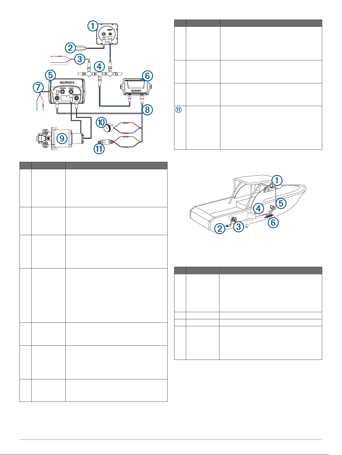
Item Description Important Considerations
Helm control
À
(or compatible
Garmin
chartplotter)
Helm control
Á
data cable
NMEA 2000
Â
power cable
NMEA 2000
Ã
network
ECU The ECU must be located within 0.5 m (19 in.) of
Ä
CCU You can mount the CCU in a non-submerged
Å
ECU power
Æ
cable
A dedicated helm control is not included in all
autopilot packages. If you install the autopilot
without a dedicated helm control, the autopilot
CCU must be connected to the same NMEA
2000 network as a compatible Garmin
chartplotter to configure and control the autopilot
system.
You should install this cable only if you are
connecting the autopilot to optional NMEA® 0183
devices, such as a wind sensor, a water-speed
sensor, or a GPS device (NMEA 0183
Connection Considerations, page 8).
You should install this cable only if you are
building a NMEA 2000 network. Do not install
this cable if there is an existing NMEA 2000
network on your boat.
You must connect the NMEA 2000 power cable
to a 9 to 16 Vdc power source.
You must connect the helm control or
compatible Garmin chartplotter and the CCU to
a NMEA 2000 network using the included Tconnectors (NMEA 2000® Connection
Considerations, page 2).
If there is not an existing NMEA 2000 network
on your boat, you can build one using the
supplied cables and connectors (Building a
Basic NMEA 2000 Network for the Autopilot
System, page 7).
the pump.
The cables connecting the ECU to the pump
cannot be extended.
location near the center of the boat, in any
orientation (CCU Mounting and Connection
Considerations, page 1).
Mount the CCU away from sources of magnetic
interference.
You must connect the ECU to a 12 to 24 Vdc
power source. To extend this cable, use the
correct wire gauge (Power Cable Extensions,
page 5).
Item Description Important Considerations
CCU cable To extend this cable to reach the ECU, you may
Ç
Pump The pump must be located within 0.5 m (19 in.)
È
Alarm The alarm provides audible alerts from the
É
Shadow Drive
valve (optional)
Autopilot
switch (not
included)
need to use cable extensions (sold separately)
(CCU Mounting and Connection Considerations,
page 1).
You must connect this cable to the alarm and
the Shadow Drive valve.
of the ECU.
The cables connecting the pump to the ECU
cannot be extended.
autopilot system, and you should install it near
the primary helm station (Installing the Alarm,
page 6).
You must install the Shadow Drive valve
properly in the hydraulic steering line, and
connect it to the CCU cable (Installing the
Shadow Drive Valve, page 6).
If your autopilot package does not include a
Shadow Drive valve, you should install a manual
Single Pole Single Throw (SPST) switch (not
included) to disable the autopilot if necessary.
Component Layout
Single-Helm Layout
NOTE: This diagram is for planning purposes only. If needed,
specific connection diagrams are included in the detailed
installation instructions for each component.
Hydraulic connections are not shown in this diagram.
Item Description Important Considerations
Helm control A dedicated helm control is not included in all
À
Á
Â
Ã
Pump
ECU
12 to 24 Vdc
battery
autopilot packages. If you install the autopilot
without a dedicated helm control, the autopilot
CCU must be connected to the same NMEA
2000 network as a compatible Garmin
chartplotter to configure and control the autopilot
system.
You must connect the ECU to a 12 to 24 Vdc
power source. To extend this cable, use the
correct wire gauge (Power Cable Extensions,
page 5).
You must connect the NMEA 2000 power cable
to a 9 to 16 Vdc power source.
3
Item Description Important Considerations
CCU You can mount the CCU in a non-submerged
Ä
Å
NMEA 2000
network
location near the center of the boat, in any
orientation (CCU Mounting and Connection
Considerations, page 1).
Mount the CCU away from sources of magnetic
interference.
You must connect the helm control or compatible
Garmin chartplotter and the CCU to a NMEA
2000 network using the included T-connectors
(NMEA 2000® Connection Considerations,
page 2).
If there is not an existing NMEA 2000 network on
your boat, you can build one using the supplied
cables and connectors (Building a Basic NMEA
2000 Network for the Autopilot System,
page 7).
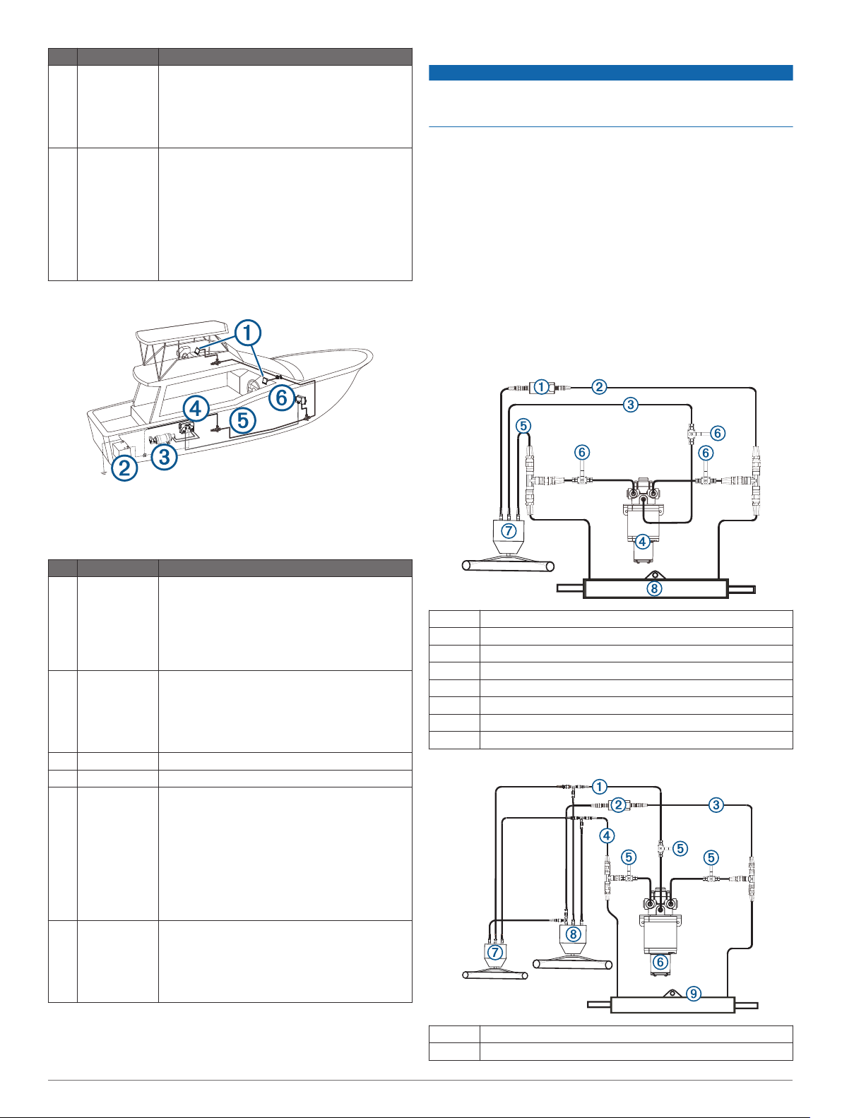
Dual-Helm Layout Guidelines
Hydraulic Layouts
NOTICE
If the steering system in your boat does not match any of the
hydraulic layouts in this manual and you are unsure how to
install the pump, contact Garmin Product Support.
Before you start the pump installation, identify the type of
hydraulic steering system in your boat. Each boat is different,
and you must consider certain aspects of the existing hydraulic
layout before deciding where to mount the pump.
Important Considerations
• The three hydraulic ports on the pump are 1/4 in. NPT.
• Garmin recommends using T-connectors to connect the
hydraulic lines to the pump.
• To allow for easy pump disabling and removal, Garmin
recommends installing shut-off valves in the hydraulic lines
between the pump manifold and T-connectors.
• Teflon® tape must not be used on any hydraulic fitting.
• An appropriate thread sealant should be used on all pipe
threads in the hydraulic system.
Single-Helm Layout
NOTE: This diagram is for planning purposes only. If needed,
specific connection diagrams are included in the detailed
installation instructions for each component.
Hydraulic connections are not shown in this diagram.
Item Description Important Considerations
Helm control A dedicated helm control is not included in all
À
12 to 24 Vdc
Á
battery
Pump
Â
ECU
Ã
NMEA 2000
Ä
network
CCU You can mount the CCU in a non-submerged
Å
autopilot packages. If you install the autopilot
without a dedicated helm control, the autopilot
CCU must be connected to the same NMEA
2000 network as a compatible Garmin
chartplotter to configure and control the autopilot
system.
You must connect the ECU to a 12 to 24 Vdc
power source. To extend this cable, use the
correct wire gauge (Power Cable Extensions,
page 5).
You must connect the NMEA 2000 power cable
to a 9 to 16 Vdc power source.
You must connect the helm control or compatible
Garmin chartplotter and the CCU to a NMEA
2000 network using the included T-connectors
(NMEA 2000® Connection Considerations,
page 2).
If there is not an existing NMEA 2000 network on
your boat, you can build one using the supplied
cables and connectors (Building a Basic NMEA
2000 Network for the Autopilot System,
page 7).
location near the center of the boat, in any
orientation (CCU Mounting and Connection
Considerations, page 1).
Mount the CCU away from sources of magnetic
interference.
À
Á
Â
Ã
Ä
Å
Æ
Ç
Shadow Drive valve
Starboard line
Return line
Pump
Port line
Shut-off valves
Helm
Steering cylinder
Dual-Helm Layout
À
Á
4
Return line
Shadow Drive valve
 Loading...