

Page 1
PCX5 / PCX5AVD / PC150
v
e
PC SOFTW ARE KIT
OWNER'S MANUAL
Personal Na
Maintenance and R
Page 2

PCX5/PCX5AVD/PC150
PC Software Kit
OWNER'S MANUAL
Page 3

AutoSketch® is a registered trademark of Autodesk, Inc.
GARMINTM, Personal NavigatorTM, and the GARMIN logo are trademarks of
GARMIN International.
IBM® and IBM Personal Computer® are registered trademarks of International
Business Machines Corporation.
LaserJet® is a registered trademark of Hewlett-Packard Company.
MS-DOS®, Word®, Windows® and Microsoft® are registered trademarks of
Microsoft Corporation.
QualitasTM and 386 MAX
TM
are trademarks of Qualitas, Inc.
ZincTM is a trademark of Zinc Software Incorporated.
© 1999 GARMIN Corporation
GARMIN International, Inc.
1200 E. 151st Street, Olathe, KS 66062 USA
(913) 397-8200
GARMIN (Europe) Ltd.
Unit 5, The Quadrangle, Abbey Park, Romsey, Hampshire, SO51 9AQ, UK
GARMIN (Asia) Corp.
3F, No. 1, Lane 45, Pao-Hsing Road, Hsin Tien, Taipei, Taiwan R.O.C.
Printed in Taiwan.
All rights reserved. No part of this manual may be reproduced or transmitted
in any form or by any means, electronic or mechanical, including photocopying
and recording, for any purpose without the express written permission of
GARMIN.
Information in this document is subject to change without notice. GARMIN
reserves the right to change or improve their products and to make changes
in the content without obligation to notify any person or organization of such
changes or improvements.
February 1999 190-00045-00 Rev. D
Page 4

PREFACE
GARMIN thanks you for selecting our PCX5/PCX5AVD/PC150 software
package. The PCX5/PCX5AVD/PC150 software is designed to enhance
and compliment the capabilities of your GARMIN Personal NavigatorTM. This
software package represents our continued commitment to provide you with
the most versatile, easy to use - and now the most complete - navigation
system possible. We are confident you will enjoy the PCX5/PCX5AVD/
PC150 software and the additional capabilities it provides your GARMIN
GPS unit.
This manual provides complete information on operating the PCX5/PCX5AVD/
PC150 software to its full potential. Sample data has been provided to get
you started. The manual is divided into two parts. Chapters 1 through 9
discuss features which are common to all three software packages. All
references in these chapters will be made to the PCX5 software, but they
apply to all software packages. Chapter 10 will highlight the features specific
to the PCX5AVD and PC150 software. Chapter 11 will highlight features
specific to the PC150 software only. Please review these chapters if you
have purchased the PCX5AVD or PC150 package so you may gain full use
of its capabilities. If you have any questions or comments, our Product
Support Department is eager to serve you. GARMIN is fully committed to
your satisfaction as a customer.
Page 5

T ABLE OF CONTENTS
CHAPTER PAGE
1 INTRODUCTION 1-1
1.1 Overview 1-1
1.2 Conventions Used in this Manual 1-2
1.3 Sample Files 1-2
2 INSTALLATION 2-1
2.1 Package Contents 2-1
2.2 System Requirements 2-1
2.3 Video Considerations 2-2
2.4 Mouse Considerations 2-2
2.5 Performance Considerations 2-3
2.6 Installation 2-3
2.7 Error Messages 2-3
2.8 Upgrading From An Earlier Version 2-4
3 GETTING STARTED 3-1
3.1 Running PCX5 3-1
3.2 Accessing Menus and Selecting Options 3-2
3.3 Dialog Boxes 3-4
3.4 File Extensions 3-5
4 FILE MENU OPERATIONS 4-1
4.1 Open File to Plot 4-1
4.2 Save Plot to File 4-4
4.3 Save Plot As 4-4
4.4 Clear Plot 4-4
4.5 Convert to DXF Format 4-5
4.6 File Utilities 4-6
4.7 Print Screen 4-6
4.8 About 4-7
4.9 Exit 4-7
Page 6

5 EDIT MENU OPERATIONS 5-1
5.1 Waypoint Editor 5-1
5.2 Route Editor 5-3
5.3 Range and Bearing Between Two Points 5-5
6 COMM MENU OPERATIONS 6-1
6.1 GARMIN File Format 6-2
6.2 Download Data from Unit 6-3
6.2.1 Download Waypoint Data 6-3
6.2.2 Download Proximity Waypoint Data 6-4
6.2.3 Download Route Data 6-5
6.2.4 Download Track Data 6-6
6.2.5 Download Almanac Data 6-6
6.3 Upload Data to Unit 6-7
6.4 Real time Plotting/Logging 6-9
6.5 Comm Port 6-11
7 PLOT MENU OPERATIONS 7-1
7.1 Zoom In 7-1
7.2 Zoom Out 7-2
7.3 Zoom Extents 7-2
7.4 Zoom Window 7-2
7.5 Pan Window 7-3
7.6 Refresh Screen 7-3
8 SATVIS MENU OPERATIONS 8-1
8.1 SkyView 8-1
8.2 DOP/Bar Chart 8-4
9 CONFIG MENU OPERATIONS 9-1
9.1 Units Configuration 9-1
9.2 Coordinate System Configuration 9-2
9.3 Datum Configuration 9-3
9.4 Config Display Options 9-4
9.5 Miscellaneous 9-5
9.6 Load Configuration 9-6
9.7 Save Configuration 9-6
9.8 Save on Exit 9-6
Page 7

10 PCX5AVD 10-1
10.1 Setup and Installation 10-1
10.2 Menu Differences 10-2
10.2.1 Convert to DXF Format 10-2
10.2.2 Waypoint Editor 10-3
10.2.3 Config Display Options 10-4
10.3 Additional Features 10-4
11 PC150 11-1
11.1 Setup and Installation 11-1
11.1.1 Checklist Editor 11-1
11.1.2 Schedule Editor 11-2
11.2 Additional Features 11-3
12 CONNECTING THE GPS UNIT TO A COMPUTER 12-1
APPENDICES
A GLOSSARY A-1
B INDEX B-1
Page 8

CHAPTER 1
INTRODUCTION
1.1 OVERVIEW
The PCX5 Software Kit is designed for use with GARMIN GPS units which
do not contain a Jeppesen aviation database (i.e., 40, 45, 75 etc.). The
PCX5AVD Software Kit is designed for use with GARMIN GPS units which
do contain Jeppesen databases (i.e., 55AVD, 95XL etc.). The PC150
Software Kit is designed for use with the GARMIN GPS 150 aviation unit.
The PCX5 software provides considerable capabilities for processing,
analyzing, displaying and outputting the data collected by your GARMIN
Personal NavigatorTM. This software package covers most aspects of using
a GPS system to collect and process position data for mapping, navigation
and planning applications.
Running on an IBM compatible PC, the PCX5 software can be used to:
· Download route, waypoint, proximity waypoint, almanac and
track data collected by your GARMIN GPS unit for analysis, plotting
and processing.
· Convert route, waypoint and track files to DXF format for interfacing
with other CAD systems (e.g., AutoSketch® ).
· Display digital map in real time for mapping and navigation guidance.
· Graphically plot data files with zooming, panning and distance
calculation capabilities.
· Print plot files to your system printer for track analysis.
· Edit and upload routes, waypoints, proximity waypoints and
track data to your GPS unit for navigational guidance.
· Upload almanac data to your GPS unit for quick satellite acquisition.
· Create satellite visibility charts for trip planning using almanac
data collected by your GPS unit.
1-1
Page 9

1.2 CONVENTIONS USED IN THIS MANUAL
Commands to be typed from the computer’s keyboard are in italics. The
action to be taken is in all capital letters (e.g., “TYPE”). For example,
“TYPE:
means you should type the word “PCX5” on the computer keyboard.
Specific computer keys are enclosed in angle brackets. For example,
“
CD GARMIN
means you should type the command “CD GARMIN”, followed by pressing
the <Enter> key.
Two keys separated by a plus sign (“+”) should be pressed simultaneously
(e.g., <Alt+F4>).
Multiple menu selections are separated by a vertical line (“l”). For example,
“Config l Units Menu”
means you would select the “Config” menu, followed by the “Units” menu.
1.3 SAMPLE FILES
The original diskette contains several sample files that are copied to your
program directory during installation. These sample files can be used to
experiment with the PCX5 program as you read through this manual. These
sample files include the following:
PCX5
”
<Enter>”
SAMPLE.ALM Almanac file for the week the PCX5 program was
released. (Note: This sample is provided for
demonstration use only. For best performance,
almanac data should be less than one month old.)
SAMPLE.PRX Proximity waypoint file containing several proximity
waypoints.
SAMPLE.TRK Track log file containing over 100 points.
SAMPLE.RTE Route file containing several short routes.
SAMPLE.WPT Waypoint file containing several waypoint locations.
1-2
Page 10

WORLD.GRM Plot file consisting of worldwide geopolitical and
coastal boundaries (NOTE: This file requires
approximately two megabytes of expanded memory
to load. It is provided for your own personal use and
GARMIN assumes no responsibility for the accuracy
of the data.) Due to the large size of this database,
plotting efficiency will be decreased.
1-3
Page 11

CHAPTER 2
INSTALLATION
2.1 PACKAGE CONTENTS
Your PCX5 Software Kit includes the following items:
1) Files obtained by installing software include:
· PCX5.COM - Main program
· README.TXT - May contain pertinent notes, information about
the latest release
· Sample data files
· Auxiliary files required by PCX5
NOTE: The above files are in compressed format. See Section 2.6 for
installation instructions.
2) PC Interface Cable
3) This Owner’s Manual
2.2 SYSTEM REQUIREMENTS
Minimum
Highly recommended
DOS Memory Requirements:
For the PCX5 software to function correctly, you must have a minimum of
435K of DOS memory free before running the program. To determine the
amount of free memory, execute the following command:
PC configuration required:
· IBM-compatible computer (AT, 386 or 486)
· 640K memory
· 3.5” (1.44 Mb) floppy disk drive
· Hard Disk Drive
· EGA or VGA Graphics Adaptor
configuration (for speed considerations):
· 386 or better processor
· 2 Megabytes RAM or more
· LIM 3.2-compatible Expanded Memory Driver (EMS, up to 16 Mb, is
used to store plot files)
· VGA Graphics Adaptor
· Microsoft®-compatible mouse
2-1
Page 12

For DOS versions 5.0 and above TYPE: “
MEM
<Enter>”
For DOS versions prior to 5.0 TYPE: “
If you do not have enough memory to execute the software, there are several
techniques for freeing up DOS memory. You should remove any unneeded
TSRs (Terminate and Stay Resident programs). If your DOS version is 5.0
or above, you may alternatively attempt to load these programs into “high”
memory. If you have a version of DOS prior to 5.0, it is recommended that
you upgrade to the latest version. If the above steps do not provide the
required free memory, there are third-party memory management tools
(such as Qualitas' 386 MAXTM) that may be of assistance.
2.3VIDEO CONSIDERATIONS
The PCX5 software will function with any video card that adheres to the EGA
or VGA graphics standards. If necessary, make sure that the proper
graphics driver is installed in your system, according to the type of monitor
and video card being used.
The PCX5 software automatically detects the presence of an EGA or VGA
graphics adaptor. Some graphics adaptors may not be correctly detected.
You may force the software into EGA mode by specifying the “-EGA” flag on
the command line, as shown below:
“
PCX5 -EGA
<Enter>”
CHKDSK
<Enter>”
2.4 MOUSE CONSIDERATIONS
A mouse is not required to run the PCX5 software, although some
features require a mouse. Operations requiring a mouse include:
· Distance calculation between two points
· Zoom Window operation
· Pan Window operation
PCX5 software will work with any Microsoft®-compatible mouse or any
pointing device (e.g., trackball, light pen) that emulates a Microsoft® mouse.
If you plan to use a mouse with the PCX5 program, make sure the proper
mouse driver is installed in your system.
2-2
Page 13

2.5 PERFORMANCE CONSIDERATIONS
The PCX5 software has the capability to load part of itself into expanded
memory. This greatly increases the execution speed of the software.
Additionally, some (or all) plot data may be loaded into expanded memory.
Up to 16 megabytes of expanded memory may be used by this software,
giving it the capability to display very large plot files. (Approximately 16,000
points/megabyte times 16 megabytes = 256,000 points!)
Use of a disk caching program, such as Microsoft® Smartdrive, will improve
performance by reducing access time to/from the disk drive. For information
on setting up a disk cache, refer to your computer’s operating system
documentation.
2.6 INSTALLATION
Before actually installing the PCX5 program, you should make a backup
copy of your original diskette and place the original in a safe place.
To install the software onto a hard drive, insert the diskette into the floppy
drive (i.e., drive “A:”) and run the installation program:
A:INSTALL target directory
where “A:” is the appropriate floppy drive and “target directory” is the
directory on the hard drive in which the software is to reside. The install
program will automatically copy the required files into the specified directory.
Once installed, consult the README.TXT file for any changes or additions
not covered in this manual.
2.7 ERROR MESSAGES
The PCX5 software expects to find related support files in the same MS-DOS
directory as the executable, PCX5.COM. If in the process of running the
program, it cannot find one of these support files, an error message will be
displayed:
ERROR! - Cannot locate file: <file>
Please reinstall the software from your distribution disk(s).
2-3
Page 14

If this message occurs, the first thing to check is that your MS-DOS PATH
environment variable points to the PCX5 program directory. If that is not the
problem, then reinstall the software from the distribution disks. If the
installation succeeds, then you can be certain all the files are present. If the
problem still persists, then please contact a Garmin Product Support
representative.
2.8 UPGRADING FROM AN EARLIER VERSION
For users upgrading from an earlier version of the PCX5 software, the file
utility “GRMCONV.EXE” can be used to convert data files from the older
version file formats. The convert utility supports the following file conversions:
1. PCX5 1.02 to PCX5 2.03
2. PC100S2 1.02 to PCX5 2.03
3. PCX5AVD 1.00 to PCX5 2.03
Figure 2-1 shows the main menu of the file conversion utility. The current
version number of the files are shown on the right side of the screen. The user
can select (tag) the desired files to be converted with the space bar. The user
can then select the desired conversion type by selecting options 1, 2 or 3.
The selected files will then be converted. The conversion utility saves a
backup version of the data file with the last two characters of the file extension
renamed to “$$”. GARMIN files of extension WPT, PRX, RTE and TRK can
be viewed by highlighting the file name and pressing the <ENTER> key. The
<ESC> key will exit the view mode.
Other file conversion options available are:
F2 - tag all files
F3- untag all files
Q - Quit (exit)
Figure 2-1: FILE CONVERSION UTILITY
2-4
Page 15

CHAPTER 3
GETTING STARTED
3.1 RUNNING PCX5
The DOS command line syntax for executing PCX5 is:
PCX5 [-cXXX.cfg] [-ega] [-mc<n1>] [-me<n2>]
The optional parameters (shown in brackets) denote:
-cXXX.cfg
-ega
-mc<n1>
-me<n2>
After invoking PCX5, the main program screen will appear as illustrated
below:
configuration file to be loaded. “XXX” is any pre-defined
configuration file (see Section 9.6). If no configuration file
is specified, “PCX5.CFG” is used (either from the current
directory, if available, or from the program directory).
forces display into EGA mode (see Section 2.3).
amount of conventional memory to allocate for plotting.
“<N1>” is the amount in Kbytes. If unspecified, the program
will use what it needs from available memory.
amount of expanded memory to allocate for plotting. “<N2>”
is the amount in 16K-bytes. If unspecified, the program will
use what it needs from available memory.
Figure 3-1: MAIN MENU
3-1
Page 16

3.2 ACCESSING MENUS AND SELECTING OPTIONS
Menus may be pulled down by using one of the following methods:
· Keyboard - Press <Alt> and the underlined letter key from the desired
menu label.
· Mouse - Direct the screen arrow to the appropriate menu label and click
the left mouse button.
For either of the methods mentioned, pressing the left and right arrow keys
will cycle from menu to menu. A displayed menu can be cleared from the
screen by clicking the left mouse button off the menu or pressing <Esc>.
Once a menu is pulled down, you may select an item from the menu using
one of the following methods:
· Keyboard - Press the arrow keys to move the highlight bar between
menu options; press <Enter> to select the highlighted option.
· Keyboard (“Speed Keys”) - Press the underlined letter to select the
desired menu option.
· Mouse - Click the left mouse button on the desired menu item (the
highlight bar will follow the pointer). Or, you may hold down the left
mouse button as you move the pointer up/down the menu and release
the button to select the item under the highlight bar.
· Any window or dialog box may be closed by pressing <Alt+F4>.
A short description of what operations are available with each menu follows.
The File menu contains options for file operation and program control:
· Open an ASCII data file and plot the data on the PC screen
· Save current screen plots to the current file
· Save current screen plots to a specific file
· Clear the screen plotting area
· Convert an ASCII data file to DXF format
· Perform various file utilities (delete, copy, rename)
· Print screen plot
· View information about the current version of PCX5
· Exit the PCX5 program
3-2
Page 17

The Edit menu contains options for creating or editing file data:
· Waypoint editor
· Route editor
The Comm menu contains options for transferring various types of data
between your GPS unit and a PC:
·
Download
·
Upload
· Display real time data in graphical form
· Communications port selection
The Plot menu offers options for customizing the screen plotting parameters:
(from GPS unit to PC) Waypoint data
Proximity Waypoint data
Route data
Track data
Almanac data
(from PC to GPS unit) Waypoint data
Proximity Waypoint data
Route data
Track file data
Almanac data
· Zoom in
· Zoom out
· Fit current plot to screen (Zoom Extents)
· Draw a window around a specific portion of screen plot and zoom in
· Pan to a specific point on your graph
· Refresh (update) screen
The SatVis menu gives you options to preview satellite visibility information:
· Animated satellite sky view for a specific location and time
· DOP/satellite availability chart for a specific location and time
3-3
Page 18

The Config menu contains setup options:
· Select units distance, error/velocity and number of precision digits
· Choose coordinate system (e.g., latitude/longitude, UTM/UPS)
· Select a pre-defined map datum, or define your own
· Enable or disable plot display for Points
Lines
Identifiers
Descriptions
Proximity
· Specify Display Aspect Ratio
· Display all routes, no routes or one specific route
· Configure time difference between PC time (local) and UTC (Greenwich)
· Save or load a configuration file
· Enable configuration file Auto Save function
“Accelerator keys” are available for some menu options which enable you to
select an option without pulling down the menu. Accelerator keys, which are
available for all Plot Menu options and some File Menu options, are displayed
beside the option name and are in the form <Ctrl+key>, where “key” is a
specified letter. For example, pressing <Ctrl+I> performs the Plot Menu
“Zoom In” function.
3.3 DIALOG BOXES
Certain menu options require the entry of additional information. The PCX5
program prompts you for the necessary information using a dialog box. A
dialog box consists of a set of control items with which you may interact using
the mouse or keyboard. Figure 3-2 shows an example of a typical dialog box.
Figure 3-2: DIALOG BOX EXAMPLE
3-4
Page 19

You may move within a dialog box using one of the following methods:
· Keyboard - Use <Tab> to cycle through the various selections;
<Shift+Tab> will move your cursor in the opposite direction. Within
a list box (e.g., a list of files or directories) or inside a group of option
buttons, use the arrow keys to move among the options.
· Mouse - Move the screen pointer to the desired area and click the
left mouse button.
Within a list box, with the mouse double-click the left button on the desired
file or directory. Without a mouse, use the tab and arrow keys to highlight the
desired file or directory, press <Enter> to display that selection in the File
Name box, tab to the “OK” control button and press <Enter> (or press
<Alt+O>).
To select an option button within a given group, move the screen pointer
to the button which you want to “set” using <Tab>, or use the mouse to move
the pointer to the desired button, and click the left mouse button.
Once the appropriate selections/entries have been made, move the cursor
to the “OK” control button and press <Enter>, or use the mouse to select the
“OK” button with a single left-button click. This will cause the chosen menu
operation to begin execution. To exit the dialog box without beginning
execution, select the “CANCEL” control button (or press <F3>).
3.4 FILE EXTENSIONS
As data is transferred between the GPS unit and a PC, five types of ASCII
data files are used, each denoted by a different file extension:
.TRK -- Track File
.RTE -- Route File
.WPT-- Waypoint File
.PRX -- Proximity Waypoint File
.ALM -- Almanac Data from unit (“YUMA” format)
.CHK -- Checklist File (PC150 Only)
.SCH -- Schedule File (PC150 Only)
Data that is created or modified on the PC will be saved to a sixth type of file:
.GRM-- GARMIN Format File
The formats of these files are detailed in Sections 6.1 and 6.2.
3-5
Page 20
CHAPTER 4
FILE MENU OPERATIONS
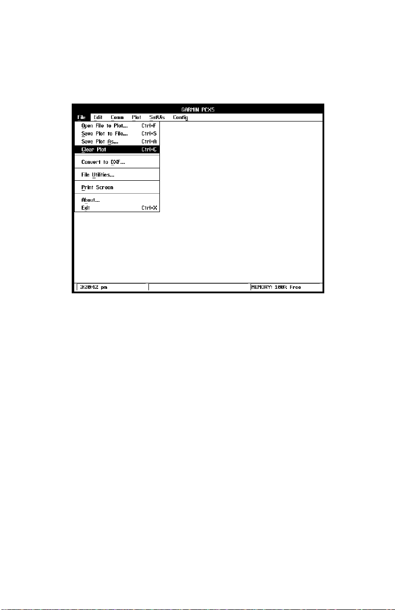
Figure 4-1: FILE MENU
From the File Menu you may perform various operations with data files
produced by your GPS unit and/or the PCX5 program. You may open a file
for plotting to the screen, save the screen plot to a “.GRM” file, clear a screen
plot, convert an ASCII file into DXF format, perform various file utilities, print
the current plot or exit the PCX5 program.
4.1 OPEN FILE TO PLOT
This option graphically plots data from an ASCII file to your PC screen using
the parameters selected from the Plot and Config Menus, described in
Chapters 7 and 9. The input file required for this option may be a file created
during a previous Download operation (e.g., .TRK, .RTE, .WPT, .PRX) or a
file in the GARMIN (.GRM) format as described in Section 6.1.
Upon choosing this selection, a dialog box will prompt you for the required
information (drive, directory and file name).
4-1
Page 21
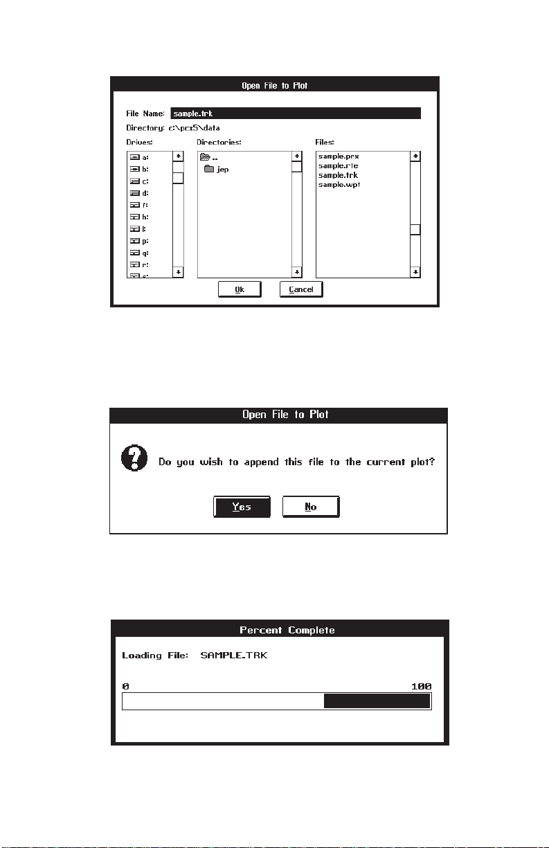
Figure 4-2: OPEN FILE TO PLOT DIALOG BOX
Enter the required information and select the “OK” button to begin the
operation. If a plot is already loaded, another dialog box will prompt you
whether to append to or clear the existing plot.
Figure 4-3: APPEND PLOT DIALOG BOX
A bar graph will be displayed as the file is loading. The ESC key can be
used to abort the load.
4-2
Figure 4-4: FILE LOAD BAR GRAPH
Page 22
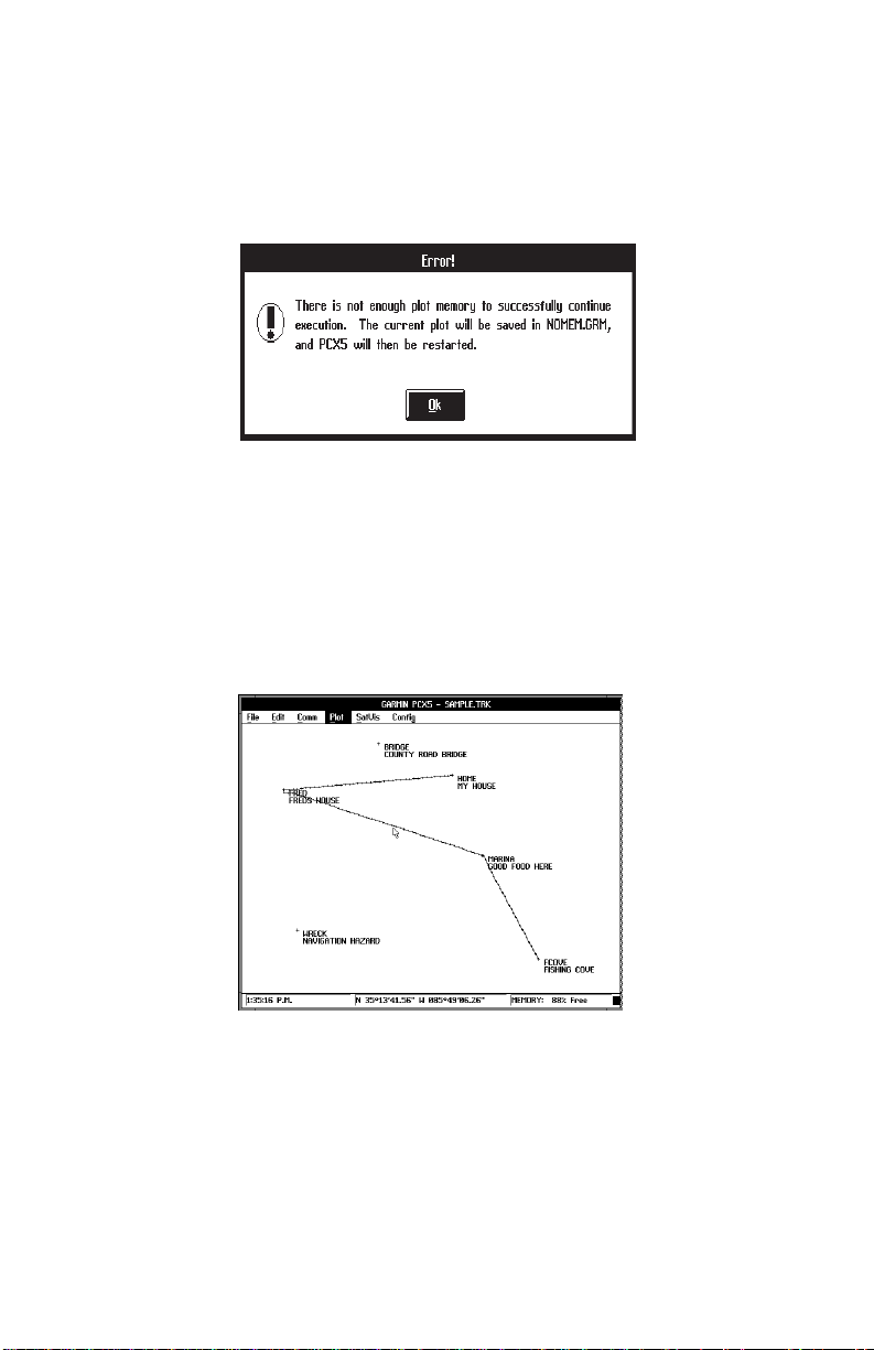
As the file is loading, the PCX5 program may determine there is not enough
memory to load the entire file. Should this occur, sufficient memory is not
available for the PCX5 program to continue functioning properly and you
should exit the PCX5 program immediately.
Figure 4-5: MEMORY LIMITATION WARNING
The title bar, at the top of the display, will always indicate the file name of the
last plot file loaded or saved.
GARMIN data files may contain multiple data types (e.g., waypoints, track,
proximity information, etc.). The type of data displayed will depend on the
settings in the Config | Config Display Menu (see Section 9.4).
Figure 4-6: PLOT FILE EXAMPLE
Once the file is displayed, you can use the Plot Menu options (Chapter 7) to
customize the display of your data, Config Menu options (Chapter 9) to
change the units used for display or find the range and bearing between any
two points simply by clicking on them (Section 4.2).
4-3
Page 23

If the Error Dialog Box is displayed, PCX5 is trying to open a file not created
by the current PCX5 version (i.e., created by either a different version of the
PCX5 program or another software package). The data file will not be loaded
and the error box shown in Figure 4-7 will appear.
Figure 4-7: ERROR DIALOG BOX
4.2 SAVE PLOT TO FILE
This menu option automatically saves a copy of the data currently plotted on
your PC monitor (i.e., waypoints, routes) to the currently loaded data file.
The data is saved in the currently selected coordinate system format
(e.g., Latitude/Longitude, UTM/UPS, etc.). If more than one file is currently
loaded, the data will be saved to the file loaded last (named on the top display
line).
4.3 SAVE PLOT AS
This menu option allows you to save a copy of the data currently plotted on
your PC monitor (i.e., waypoints, routes) to an ASCII data file. The data is
saved in the currently selected coordinate system format (e.g., Latitude/
Longitude, UTM/UPS, etc.). To use this option, enter the requested
information into the dialog box (drive, directory and file name) and select the
“OK” button to save the file.
4.4 CLEAR PLOT
The clear plot menu option will clear all plot data displayed by the program.
4-4
Page 24

4.5 CONVERT TO DXF FORMAT
This menu option gives you the capability to convert ASCII data files (e.g.,
track plots, waypoint and route files) into DXF format required for various
CAD programs. To use this option, enter the information required for the file
to be converted (drive, directory and file name) into the dialog box.
A second dialog box will appear to select the drive, directory and file name
for the output file. The default file name is the input file name with a “.DXF”
extension. Select “OK” to continue.
Figure 4-9: OUTPUT FILE DIALOG BOX
Figure 4-10: CONVERSION OPTIONS DIALOG BOX
4-5
Page 25

The DXF Conversion Options dialog box will prompt you for conversion
parameters. Select between “Metric”, “Nautical” or “Statute” to indicate the
type of units into which you wish the data converted. Select between “Points”
or “Lines” to designate whether the data shall be converted as discrete points
or connected by lines. Indicate the waypoint text to be converted: identifier
and/or descriptions. Enter the height for text characters expressed as the
percentage of the vertical extent of the current plot. The default is 3%. The
2D option eliminates the altitude data (some GPS units do not support
altitude) for a 2-dimensional DXF export to programs such as Microsoft
Word® for Windows. Select “OK” to begin the file conversion.
4.6 FILE UTILITIES
This menu option gives you the capability to delete, copy or rename your
DOS files. To use this option, fill in the file information (drive, directory and
file name). Select the DELETE button to delete the file; the COPY button to
copy the file to another drive, directory or file name; or the RENAME button
to give the file a different name.
Figure 4.11: FILE UTILITIES BOX
If COPY or RENAME is selected, a second dialog box will be displayed
prompting for the Copy Destination file name or the New file name. Select
DONE to indicate file changes are complete.
4.7 PRINT SCREEN
This option allows you to print the contents of the current screen plot. Prior
to running the PCX5 program, from the DOS prompt, execute the DOS
“GRAPHICS” command with the proper parameters and designation for your
printer. For example, the following command line sets up a Hewlett-Packard
LaserJet II for printing in reverse mode (black w/ white background):
GRAPHICS LASERJETII /R
4-6
Page 26

After executing the PCX5 software and the desired screen is displayed,
select Print Screen. Refer to the user’s guide provided with your computer’s
operating system for additional information on using the “GRAPHICS”
command.
4.8 ABOUT
This option allows you to view information about the current version of the
PCX5 software. Select “OK” to continue.
Figure 4-12: ABOUT PCX5 DIALOG BOX
4.9 EXIT
This option allows you to exit from the PCX5 program. You may also exit
without pulling down the File menu by using the accelerator key <Ctrl+X>.
If the current plot has been modified, a dialog box will remind you to save the
file.
Figure 4-13: SAVE PLOT DIALOG BOX
If the SAVE ON EXIT option is selected on the Config Menu (see Section 9.8),
all currently selected configuration parameters (e.g., Comm Port, Units,
Coordinates) will be saved to the configuration file upon exiting the PCX5
program. If no customized configuration file was specified, configuration
parameters will be written to the default configuration file, PCX5.CFG (see
Section 9.7).
4-7
Page 27

CHAPTER 5
EDIT MENU OPERATIONS
Figure 5-1: EDIT MENU
The Edit menu allows you to create or modify waypoint and route files.
5.1 WAYPOINT EDITOR
The waypoint editor allows you to create or modify waypoints. The waypoints
from the “sample.wpt” waypoint file are listed as illustrated below.
Figure 5-2: WAYPOINT SELECT DIALOG BOX
5-1
Page 28

To edit an existing waypoint, select it with the left mouse button (or the arrow
keys), then select EDIT to display the Waypoint Edit dialog box as illustrated
below.
Figure 5-3: WAYPOINT EDIT DIALOG BOX
Change the position of the waypoint either directly, by entering its coordinates,
or in reference to another waypoint by selecting the reference waypoint from
the “Ref Wpt:” list. If a reference waypoint is used, enter the distance and
bearing from the reference waypoint, and the new waypoint position will be
calculated (great circle) and displayed in the coordinate fields. Select the
“OK” button to save the changes to the waypoint, or “CANCEL” to abort the
waypoint modification.
To create a new waypoint, select the ADD control button from the Waypoint
Select dialog box. A blank Waypoint Edit dialog box will be displayed. Enter
the new waypoint identifier and its description (optional). Enter its coordinates
directly, or select a reference waypoint and enter a distance and bearing.
Select the “OK” button and the new waypoint will be added to the list.
If a plot is being displayed, you may go directly to the Waypoint Edit dialog
box (skipping the Waypoint Select dialog box) by double-clicking the right
mouse button on the plotted waypoint. Similarly, double-click on an open
position to create a new waypoint.
To delete a waypoint, click on the waypoint in the Waypoint Select Box, and
select the DELETE control button. Or, double-click on the plotted waypoint
and select the DELETE control button in the Waypoint Edit dialog box.
When all modifications to the waypoint data have been made, select the
DONE control button to exit the waypoint editor.
5-2
Page 29

Remember, waypoint changes only affect the displayed plot - you must
save the plot to a file to save any changes you have made. An icon of
a diskette will be displayed in the lower right corner of your screen to remind
you that the current plot has been modified.
NOTE: The PCX5 software waypoint editor will process up to a total of 500
waypoints to maintain compatibility with a greater number of Garmin GPS
units. Your GPS unit may have a lower waypoint capability. Additionally your
unit may not support the use of proximity waypoints.
5.2 ROUTE EDITOR
This menu option allows you to create or modify routes. The routes from the
“sample.rte” (plotted) route file are listed as illustrated below.
Figure 5-4: ROUTE EDIT DIALOG BOX
To enable graphical editing of an existing route, select it with the left mouse
button and it will be displayed in the edit field (or use the arrow keys and
<ENTER>). Copy the selected route to an empty route by selecting the
COPY button and designating the destination route number. Reverse the
selected route by selecting the INVERT button. Delete the selected route by
selecting the DELETE button. Abort changes made to the routes by selecting
the CANCEL button.
The sequence of the waypoints in a route is modified graphically on the plot
screen. Select “OK” to plot the selected route graphically. “View One Route”
mode will automatically be selected (see Section 9.4).
5-3
Page 30

The first waypoint in the route will be highlighted (“selected”). Select other
route waypoints using the left and right arrow keys. By pressing <Shift> plus
the left or right arrow key, you can move between all displayed waypoints
(including those not in the displayed route). You may also select any
waypoint by clicking the right mouse button on it.
NOTE: While in Route Editing Mode, Range/Bearing and Waypoint Editor
functions cannot be activated using the right mouse button.
Figure 5-5: ROUTE EDIT EXAMPLE
To insert a waypoint into the displayed route, select the waypoint (with the
right mouse button) which is to precede the inserted waypoint. “Drag” the
mouse (while holding down the right mouse button) and release it at the
waypoint to be inserted. The cursor will snap-to the waypoint. The route will
be re-drawn, inserting the selected waypoint into the route immediately
following the first selected waypoint. (To insert a waypoint without a mouse,
select the waypoint to precede the inserted waypoint and press <Insert>.
Move to the waypoint to be inserted into the route using the arrow keys, or
<Shift> and the arrow keys. When the waypoint to be inserted is selected,
press <Enter>.)
To insert a waypoint at the beginning of a route, select the waypoint which
is to be inserted. “Drag” the mouse and release it at the first waypoint in the
route. (To insert a waypoint at the beginning without a mouse, select the
waypoint to be inserted and press <Insert>. Select the first waypoint in the
route using the arrow keys, or <Shift> plus the arrow keys, and press
<Enter>.)
5-4
Page 31

To create a new waypoint and insert it into the displayed route, create the
waypoint first from the Waypoint Editor (see Section 5.1). Insert the new
waypoint into the route using the procedure described above.
To delete a waypoint from the displayed route, highlight the waypoint to be
deleted and press <Delete>. To view a different route from the same route
file, press <Page Up> to display the previous route or <Page Down> to
display the next route. Changes to the current route will be saved in memory.
Route comments can be added to the route data file by selecting the route
comment field with the left mouse button. The field can then be edited with
the keyboard. Certain GPS units support the upload & download of route
comments. Other GPS units will ignore the uploaded route comments. See
Appendix B for GPS unit capability.
When all modifications to the route(s) have been made, save the plot to a file
(see Sections 4.3 and 4.4). This saves all routes from the loaded file (not
only the route currently displayed). Remember, after graphically displaying
and editing a route, “View One Route” mode will be the current configuration
selection.
NOTE: The PCX5 route editor will process up to a total of twenty routes and
forty waypoints per route to maintain compatibility with a greater number of
GARMIN GPS units. Your GPS unit may have a lower route and waypoint
capability. See Appendix B for the route and waypoints per route capability
of your unit.
5.3 RANGE AND BEARING BETWEEN TWO POINTS
PCX5 will display Great Circle relationships between two selected points.
The Great Circle range and bearing are based on the shortest distance
between two points over the surface of the earth. All information is
referenced to True North (as opposed to Magnetic North).
Place the cursor on the first point (the “from” point) and click the right mouse
button. You may select any location on the plot, including waypoints or track
log points. The cursor will “snap to” a waypoint if it is close to the cursor. The
status line at the bottom of the screen will remind you that “Range/Bearing”
mode is active.
Move the cursor and click the right mouse button on the second point (the “to”
point). A dialog box will display the coordinates of each point and the Great
Circle range and bearing between them.
5-5
Page 32

NOTE: The Range/Bearing function will not work when in a Route Editing
Mode (i.e., when anything other than “view none” is selected on the
Config | Config Display Menu).
Figure 5-6: RANGE AND BEARING DIALOG BOX
5-6
Page 33

CHAPTER 6
COMM MENU OPERATIONS
Figure 6-1: COMM MENU
The Communications menu allows you to transfer data between your GPS
unit and a PC, monitor real time position data from the GPS unit or select the
communications port to be used. The proper COM port must be selected
prior to beginning a data transfer (see Section 6.5). The unit must be
configured with the appropriate output selected on the Interface Page:
“GARMIN” to download or upload data, or “NMEA 0183 (Version 1.5 or 2.0)”
for realtime plotting.
Data transferred between the PC and the unit is in a GARMIN proprietary
binary format. The PCX5 software converts the binary data to an ASCII
readable file format for user editing. The ASCII file format is GARMIN for:
Waypoint, Proximity Waypoint, Route, or Track Files and YUMA for almanac
files. While the data is being transferred, a bar graph will indicate the
progress of the transfer. The ESC key can be used to abort the data transfer.
NOTE: The PCX5 software will process up to 500 waypoints, 20 routes,
route comments, proximity waypoints and up to forty waypoints per route.
Your GPS unit may not support all the features available in the PCX5
software. Refer to your GPS owner's manual for the capability of your unit.
6-1
Page 34

6.1 GARMIN FILE FORMAT
Waypoint, proximity waypoint, route and track data are stored as ASCII data
files in GARMIN format, with file extensions “.WPT”, “.PRX”, “.RTE”, and
“.TRK” respectively. Real time data logged to a file is saved as ASCII data
in GARMIN format with a “.TRK” extension. Waypoint, proximity waypoint,
route and track data must also be in GARMIN format to be used by the PCX5
plotting program or uploaded to the unit..
Each GARMIN file is composed of multiple data lines (each line is a “record”).
The first character on each line is the record type, identifying the type of data
to follow.
The following lists the valid record types:
H = Header record (provides column titles only; contains no data)
I = Software Identification
M = Map Datum
U = Coordinate System
W = Waypoint record
R = Route record
T = Track record (track log file) and Real time logging record (select
NMEA output format)
C = Checklist record (PC150 Only)
S = Schedule record (PC150 Only)
The data fields associated with the record follow the record type. All fields
must be separated by spaces. Non-trailing empty fields will contain one or
more space characters.
At least one header line (H record) precedes each logical group of data lines.
For example, a ground track file may have hundreds (or thousands) of T
records, but the file may have only one H record at the beginning of the file.
The following is a list of header titles used for data fields in the various types
of GARMIN file records (units are given where appropriate):
· LATITUDE
· LONGITUDE
· DATE in form of DD-MMM-YY
· TIME in form of HH:MM:SS (UTC time)
· ALT = Altitude in meters
· ZONE = Grid coordinate zone identifier
· EASTING = Grid coordinate easting offset in meters
· NORTHING = Grid coordinate northing offset in meters
6-2
Page 35

· COORDINATE SYSTEM =coordinate system configuration (text string)
· SOFTWARE NAME & VERSION (text string)
· R = Altitude Reference (E=Ellipsoid or G=Geoid)
· DATUM = map datum used (text string)
· IDNT = Identifier (text string)
· IDX = Datum index
· DA = Delta earth radius
· DF = Delta flattening factor
· DX, DY, DZ = Delta earth center
· DESCRIPTION = Waypoint description
· PROXIMITY = Proximity distance
An example of each record type is given in the sections that follow. Note that
the time given in the points created by the unit is UTC Time; points created
by the PC are in local PC Time.
6.2 DOWNLOAD DATA FROM UNIT
This option will transfer data from the unit into a PC. From the sub-menu
select the type of data to download: Waypoints, Proximity Waypoints,
Routes, Track log or Almanac.
Figure 6-2: DOWNLOAD DATA OPTIONS
6.2.1 DOWNLOAD WAYPOINT DATA
Select “Waypoint Data” to download waypoints from the GPS unit to an ASCII
file with a “.WPT” extension. Upon choosing this selection, a dialog box will
6-3
Page 36

prompt you for the required information (drive, directory and file name).
Indicate the destination file name for the waypoint data.
Figure 6-3: WAYPOINT DOWNLOAD DIALOG BOX
The ASCII file created follows the format described in Section 6.1. The file
will include one header record (H record) followed by multiple waypoint data
records (W records). Each line begins with the waypoint record identifier (W),
followed by the user-assigned waypoint identifier. Appearing next are
latitude and longitude (or easting and northing for grid coordinates), date
(DD-MMM-YY) and time (UTC in HH:MM:SS) created, altitude, description
(if applicable) and proximity waypoint distance (if applicable). An example
of a waypoint data file in latitude and longitude (degrees/minutes/seconds)
coordinates follows:
H SOFTWARE NAME & VERSION
I PCX5 2.00
H R DATUM IDX DA DF DX DY DZ
M E WGS 84 100 +0.000000e+00 +0.000000e+00 +0.000000e+00 +0.000000e+00 +0.000000e+00
H COORDINATE SYSTEM
U LAT LON DM
H IDNT LATITUDE LONGITUDE DATE TIME ALT DESCRIPTION PROXIMITY ;waypts
W HOME N3519.3776 W08540.4503 07-JUN-93 14:26:47 -9999 MY HOUSE 0.00000e+00
W MARINA N3510.6819 W08536.0333 07-JUN-93 14:29:17 -9999 GOOD FOOD HERE 0.00000e+00
W BRIDGE N3522.8349 W08551.1903 07-JUN-93 14:30:16 -9999 COUNTY ROAD BRIDGE 0.00000e+00
W FCOVE N3459.3816 W08527.8865 07-JUN-93 14:31:15-9999 FISHING COVE 0.00000e+00
W WRECK N3502.5195 W08602.9741 07-JUN-93 14:32:44 -9999 NAVIGATION HAZARD 0.00000e+00
W FRED N3517.7816 W08605.0523 07-JUN-93 14:53:40-9999 FREDS HOUSE 0.00000e+00
NOTE: The -9999 value in the altitude field indicates that altitude information
was not available.
6.2.2 DOWNLOAD PROXIMITY WAYPOINT DATA
Select “Proximity Wpt Data” to download waypoints from the GPS unit to a
“.PRX” file. Upon choosing this selection, a dialog box will prompt you for the
6-4
Page 37

required information (drive, directory and file name). Indicate the destination
file name for the proximity waypoint data.
The ASCII file created follows the waypoint file format described in Section
6.2.1 (one “H” record followed by multiple “W” records), but with proximity
data in each waypoint record. An example of a proximity waypoint data file
in latitude and longitude (degrees/minutes) coordinates follows:
H SOFTWARE NAME & VERSION
I PCX5 2.00
H R DATUM IDX DA DF DX DY DZ
M E WGS 84 100 +0.000000e+00 +0.000000e+00 +0.000000e+00 +0.000000e+00 +0.000000e+00
H COORDINATE SYSTEM
U LAT LON DM
H IDNT LATITUDE LONGITUDE DATE TIME ALT DESCRIPTION PROXIMITY ;waypts
W HOME N3519.3776 W08540.4503 07-JUN-93 14:26:47 -9999 MY HOUSE 1.00000e+03
W MARINA N3510.6819 W08536.0333 07-JUN-93 14:29:17 -9999 GOOD FOOD HERE 2.00000e+02
W BRIDGE N3522.8349 W08551.1903 07-JUN-93 14:30:16 -9999 COUNTY ROAD BRIDGE 1.25000e+03
W FCOVE N3459.3816 W08527.8865 07-JUN-93 14:31:15-9999 FISHING COVE 2.50000e+03
W WRECK N3502.5195 W08602.9741 07-JUN-93 14:32:44 -9999 NAVIGATION HAZARD 1.60934e+03
W FRED N3517.7816 W08605.0523 07-JUN-93 14:53:40-9999 FREDS HOUSE 1.00000e+04
6.2.3 DOWNLOAD ROUTE DATA
Select “Route Data” to download stored routes from the GPS unit into an
ASCII file with a “.RTE” extension. Upon choosing this selection, a dialog box
will prompt you for the required information (drive, directory and file name).
Indicate the destination file name for the route data.
The ASCII file created follows the format described in Section 6.1 and will
show data for each route downloaded from the unit. Each grouping of data
for a specific route consists of one route identifier line (R record), one header
record (H record) and the related waypoint data lines (W records). An
example of a file created during a route download follows:
H SOFTWARE NAME & VERSION
I PCX5 2.00
H R DATUM IDX DA DF DX DY DZ
M E WGS 84 100 +0.000000e+00 +0.000000e+00 +0.000000e+00 +0.000000e+00 +0.000000e+00
H COORDINATE SYSTEM
U LAT LON DM
R 00 LETS GO FISHING
H IDNT LATITUDE LONGITUDE DATE TIME ALT DESCRIPTION PROXIMITY ;waypts
W HOME N3519.3776 W08540.4503 07-JUN-93 14:26:47 -9999 MY HOUSE 1.00000e+03
W FRED N3517.7816 W08605.0523 07-JUN-93 14:53:40-9999 FREDS HOUSE 1.00000e+04
W MARINA N3510.6819 W08536.0333 07-JUN-93 14:29:17 -9999 GOOD FOOD HERE 2.00000e+02
W FCOVE N3459.3816 W08527.8865 07-JUN-93 14:31:15-9999 FISHING COVE 2.50000e+03
R 01 BACK TO THE HOUSE
H IDNT LATITUDE LONGITUDE DATE TIME ALT DESCRIPTION PROXIMITY ;waypts
W FCOVE N3459.3816 W08527.8865 07-JUN-93 14:31:15-9999 FISHING COVE 2.50000e+03
W MARINA N3510.6819 W08536.0333 07-JUN-93 14:29:17 -9999 GOOD FOOD HERE 2.00000e+02
W FRED N3517.7816 W08605.0523 07-JUN-93 14:53:40-9999 FREDS HOUSE 1.00000e+04
W HOME N3519.3776 W08540.4503 07-JUN-93 14:26:47 -9999 MY HOUSE 1.00000e+03
6-5
Page 38

6.2.4 DOWNLOAD TRACK DATA
A track log is downloaded into an ASCII file (with extension “.TRK”) in the
format described in Section 6.1. It includes one header record (H record)
followed by multiple “track” data records (T records). Each line of position file
data begins with the track record identifier (T), followed by latitude and
longitude (or easting and northing for grid coordinates), date (in DD-MMMYY format) and time (UTC in HH:MM:SS format) recorded, and altitude. An
example of a track file (using UTM/UPS coordinates) follows:
H SOFTWARE NAME & VERSION
I PCX5 2.00
H R DATUM IDX DA DF DX DY DZ
M E WGS 84 100 +0.000000e+00 +0.000000e+00 +0.000000e+00 +0.000000e+00 +0.000000e+00
H COORDINATE SYSTEM
U UTM UPS
H ZONE EASTING NORTHING DATE TIME ALT ;track
T 15S 0345695 4312736 23-MAR-94 09:31:58 -9999
T 15S 0345652 4312736 23-MAR-94 09:32:00 -9999
T 15S 0345594 4312738 23-MAR-94 09:32:02 -9999
T 15S 0345551 4312738 23-MAR-94 09:32:04 -9999
T 15S 0345493 4312740 23-MAR-94 09:32:06 -9999
T 15S 0345435 4312741 23-MAR-94 09:32:08 -9999
6.2.5 DOWNLOAD ALMANAC DATA
Select “Almanac Data” to download stored almanac data from the GPS unit
into a YUMA formatted ASCII file with an “.ALM” extension. Upon choosing
this selection, a dialog box will prompt you for the required information (drive,
directory and file name). Indicate the destination file name for the almanac
data.
The file created will contain almanac data for each of the currently operational
satellites. While the data is transferring, a bar graph will monitor the rate of
the data transfer.
You
must
download almanac data before running the SkyView or Bar Chart
options on the SatVis Menu described in Chapter 9 (or any third-party
planning software). For best performance, satellite almanac data should be
under one month old.
An example of the information contained in the file (for one specific satellite)
follows. Note that the same block of information is repeated for each
operational satellite.
6-6
Page 39

**** Week700 almanac for PRN-02 ************
ID: 02
Health: 000
Eccentricity: 1.176691055E-02
Time of Applicability(s): 552960.00000000000
Orbital Inclination(rad): 9.566192031E-01
Rate of Right Ascen(r/s): - 7.920330169E-09
SQRT(A) (m^1/2): 5153.65771484375
Right Ascen at TOA(rad): 1.346327305E+00
Argument of Perigee(rad): - 2.795347452E+00
Mean Anom(rad): - 4.729050025E-02
Af0(s): - 3.051757812E-05
Af1 (s/s): 0.000000000E+00
week: 700
The PCX5 software will only record to the selected almanac file satellites
which are operational in the GPS constellation.
6.3 UPLOAD DATA TO UNIT
This option will upload an ASCII file of waypoint, proximity waypoint, route,
track log or almanac data from the PC to a GPS unit. The upload file must
be in the proper format. You may use a file previously created during a
waypoint, route, track or almanac download (refer to Section 6.2), or you may
use a file which you have created using the waypoint or route editor (see
Chapter 5).
Prior to beginning the Upload operation, the proper COM port must be
selected from the Comm | Comm Port Menu (see Section 6.5 or Chapter 11
for the GPS 150) and the input/output selection on the Interface Setup page
of the GPS unit must be set to “GARMIN/GARMIN” and “HOST” mode.
Existing waypoint, proximity waypoint, route and track log data in the unit will
be updated with the new information from the PC. Uploaded waypoint,
proximity waypoint, route and track log data are appended to the data
currently in the unit; except when data exists in the unit with the same
identifier (waypoint name or route number), in which case the original
unit data is overwritten.
6-7
Page 40

For example, you want to upload a route file from the PC defining Route 1
which contains two waypoints, HOME and OFFICE, into your unit which
already contains a waypoint named HOME and in which Route 1 is already
defined. Route 1 and waypoint HOME in the unit will be overwritten with
Route 1 and HOME from the data file; waypoint OFFICE will be added to the
unit’s waypoint list.
There is a limit for the maximum number of waypoints, proximity waypoints,
waypoints per route, routes, route comments and track log points which can
be stored in the GPS unit (refer to your unit’s User’s Manual for the actual
numbers). If you attempt to upload a file which has more data than the unit
can physically hold, the unit will give you a memory full message and excess
information in the file will be ignored. Also, if a specific route in your file
contains more waypoints than is allowed in a route by the unit, the route will
be stored with the maximum number of waypoints allowed in a route, and the
excess waypoints will simply be stored as new waypoints (provided memory
is available).
Upon choosing the upload selection, a sub-menu will prompt you to select the
type of data to be transferred.
Figure 6-4: UPLOAD DATA
Upon selecting either Waypoint File, Proximity Wpt File, Route File, Track
File or Almanac File, a dialog box will prompt you to specify the file to be
uploaded (drive, directory and file name). After entering the required
information, select “OK” to begin the operation.
6-8
Page 41

While the data is being transferred, the bar graph will monitor the progression
of the data transfer, and the number of data packets on the unit's Interface
Control page will increment as the data is received.
On certain units, the uploaded waypoints will not be displayed if the unit is not
in an active or simulated navigation mode, (i.e. operating indoors with poor
GPS coverage). The uploaded waypoints will be displayed on the Map Page
after a unit power is cycled or navigation becomes active.
6.4 REAL TIME PLOTTING/LOGGING
Select “Realtime Plotting/Logging” to receive real time data from the unit and
monitor your position graphically (as well as viewing it in text form).
In the Display Plot Options dialog box, select between “Add to Plot” and
“Clear Plot”. “Add to Plot” appends to the currently displayed plot; “Clear Plot”
clears the current plot prior to plotting any data.
Figure 6-5: DISPLAY PLOT OPTIONS DIALOG BOX
You must also select between “File and Screen” or “Screen Only”. “File and
Screen” logs data to a file while displaying it on your monitor (you will be
requested to specify file information); “Screen Only” displays data to your PC
screen only (you may still save the plot to a file later).
As real time data is received from the GPS unit, each position is added to the
plot on the screen. To end the data logging session, click the left mouse
button on the STOP sign icon displayed in the upper left corner of the screen
(or press <Esc>).
NOTE: During a real time logging session, options from the File, Edit,
Comm and SatVis menus are unavailable; Plot and Config menu functions
are all available.
6-9
Page 42

Figure 6-6: REAL TIME PLOT EXAMPLE
If “File and Screen” is selected, the “.TRK” file created will follow the format
discussed in Section 6.1, and may be used as an input file for many popular
spreadsheet software programs. Each row contains a position fix. Any nontrailing empty data fields in the file will contain spaces in order to maintain
column integrity.
First to appear in the file will be a header (H record) followed by one software
identification record (I record), specifying the name and version number of
the software producing the file. Next will appear another H record followed
by one coordinate system record (U record) naming the coordinate system
in which the file is formatted. A third H record follows with one map datum
record (M record) containing the following information: M (the record type);
R (the altitude reference used, E=ellipsoid); DATUM NAME (the map datum
used); IDX (the index number of the map datum); DA (delta earth radius); DF
(delta flattening factor); and DX, DY and DZ (delta earth center parameters).
Only one U record and one M record (and their associated headers) appear
in the file unless data in one of these fields changes during a logging session.
Occurring next will be another header (providing column titles) followed by
multiple real time logging data records (N records). An N record will always
include the following data: N (record type), latitude and longitude (or easting
and northing for grid coordinates), date (DD-MMM-YY) and time (UTC in
form of HH:MM:SS). The following is an example of a real time logging file:
6-10
Page 43

H SOFTWARE NAME & VERSION
I PCX5AVD 2.03
H R DATUM IDX DA DF DX DY DZ
M G WGS 84 100 +0.000000e+00 +0.000000e+00 0.000000e+00 +0.000000e+00 +0.000000e+00
H COORDINATE SYSTEM
U LAT LON DM
H LATITUDE LONGITUDE DATE TIME ALT ;track
T N3857.00698 W09444.76296 10-NOV-94 21:34:41 00340
T N3857.00698 W09444.76296 10-NOV-94 21:34:43 00341
T N3857.00698 W09444.76296 10-NOV-94 21:34:45 00340
T N3857.00698 W09444.76296 10-NOV-94 21:34:47 00340
T N3857.00698 W09444.76296 10-NOV-94 21:34:49 00340
T N3857.00698 W09444.76296 10-NOV-94 21:34:51 00340
T N3857.00698 W09444.76296 10-NOV-94 21:34:53 00340
T N3857.00698 W09444.76296 10-NOV-94 21:34:55 00339
T N3857.00698 W09444.76296 10-NOV-94 21:34:57 00339
6.5 COMM PORT
Select “Comm Port” to change the communications port setting between the
PC and the GPS unit. Once selected, a dialog box will ask you to select “COM
1”, “COM 2”, “COM 3” or “COM 4” to indicate into which serial port the ninepin D-shell (DB9) connector of the PC cable is plugged. When performing
transmit and receive operations, the program establishes a communication
link with the GPS unit using the selected COM port.
Figure 6-7: COM SELECT DIALOG BOX
6-11
Page 44

CHAPTER 7
PLOT MENU OPERATIONS
The PCX5 program allows you to control the display of your data through the
use of the Plot Menu.
Figure 7-1: PLOT MENU
“Zoom In”, “Zoom Out” and “Zoom Window” control the size of the area
displayed on your screen. “Zoom Extents” scales the plot to span the entire
display area. “Pan Window” allows you to reposition displayed data as you
specify.
7.1 ZOOM IN
This option reduces the area of the map displayed on the screen, thus
amplifying the appearance of the plot. The Zoom In function reduces the area
displayed to half its original size (i.e., the distance from corner to corner
represents half the original distance). The accelerator key for Zoom In is
<Ctrl+I>.
7-1
Page 45

7.2 ZOOM OUT
This option enlarges the area of the map displayed on the screen, thus
reducing the appearance of the plot. The Zoom Out function enlarges the plot
display area to twice its original size (i.e., the distance from corner to corner
represents two times the original distance). The accelerator key for Zoom
Out is <Ctrl+O>.
7.3 ZOOM EXTENTS
This option resets the boundaries and scale of the map such that the plot
spans the entire display area. Note that new data points which are added to
the plot after it has been fitted to the screen may not be visible in the display
area.
7.4 ZOOM WINDOW
Zoom Window is an alternate way to zoom in on a specific area of your plot.
After selecting this option, the status line on the bottom of the screen will
indicate “Zoom Mode”. The accelerator key for Zoom Window is <Ctrl+Z>.
Use the mouse to move the screen pointer near an area which you would like
to enlarge. Click the left mouse button once. A box outline will appear with
one corner attached to your screen pointer. Move the screen pointer using
your mouse until the box outline frames the area you wish to enlarge. Click
the left mouse button a second time and the area bounded by the box will be
scaled to fit your screen. To cancel the zoom window (without pressing the
left mouse button a second time), press <Esc>.
7-2
Page 46

7.5 PAN WINDOW
This option shifts the boundaries of the map displayed on the screen. Either
select “Pan Window” from the menu, press the accelerator key combination
(<Ctrl+P>) or hold down the <Shift> key to activate Pan mode (and use the
mouse). After selecting this option, the status line on the bottom of the screen
will indicate “Pan Mode”. Use the mouse to place the screen pointer on any
graph point which you wish to pan from. Click the left mouse button to select
the position. A solid line will now stretch between the “from” point and the
screen pointer. Move the pointer to the point on the graph that you want to
pan to. Click the left mouse button again and the graph will shift such that
the selected point moves from its original position to the position of the
second mouse click.
7.6 REFRESH SCREEN
Select this option to redraw the graph currently on your screen. This will clear
the display of any remnants left over from previous manipulations. The
screen will display the data according to the selected configuration. The
accelerator keys for “Refresh Screen” are <Ctrl+R> (or <F5>).
7-3
Page 47

CHAPTER 8
SATVIS MENU OPERATIONS
Since all GPS satellites are now deployed, 3D coverage with good geometry
will be available 24 hours a day worldwide. Satellite Visibility offers you a
preview of the satellite constellation visible for a specific location on a given
date, giving you the data necessary to plan your outings at times of maximum
satellite visibility.
An animated view of the satellites in orbit (over a selected location) can be
viewed, as well as line and bar graphs which detail the best times for satellite
availability.
Remember, for SatVis displays to be accurate, almanac data must be recent
(less than one month old), or updated since any major change in the satellite
constellation. Almanac data is obtained by downloading it from the GPS unit
(see Section 6.2.5).
Figure 8-1: SATVIS MENU
8.1 SKYVIEW
After selecting this option, select the almanac file to be used in calculating the
animated Satellite Visibility SkyView. Specify the name of the almanac file
you wish to load and select “OK”.
8-1
Page 48

Figure 8-2: ALMANAC SELECT DIALOG BOX
Upon selecting an almanac file, the Satellite Visibility Options dialog box will
be displayed allowing you to define the parameters used for the Satellite
Visibility SkyView display.
Figure 8-3: SATELLITE VISIBILITY OPTIONS DIALOG BOX
Enter the coordinates of the location for which satellite availability will be
previewed. Input the time and date to start the SkyView display, or select
CURRENT TIME to enter the current local time. Mask angle refers to the
minimum acceptable satellite elevation. No satellites below the angle of
elevation entered will be included in the SkyView display. Select between
3D- and 2D-Fixes, designating whether a minimum of four (3D) or three (2D)
satellites must be available. Select “OK” to begin the SkyView display.
NOTE: The SkyView display will be based on UTC time information, but
displayed as local time. For the SkyView display to be accurate, be sure to
set the UTC to local time difference on the Config | Miscellaneous Menu (see
Section 9.5).
8-2
Page 49

Figure 8-4: SATELLITE VISIBILITY SKY VIEW
The “North Up” format locates your selected position at the center of nine
concentric rings. The outermost ring represents the horizon at this location;
the next smaller ring represents 10° elevation above the horizon. Each
successive ring depicts another 10° above the horizon, with the center of the
sky chart (cross hair) representing the sky directly above the selected
location.
All satellites which are visible at the selected location and at the indicated
time (and are at an elevation at, or above, the entered mask angle) are plotted
on the sky chart at their appropriate elevations and azimuths. Knowing the
azimuth and elevation of each visible satellite is useful in determining
whether its signal will be blocked by buildings, mountains or other obstructions.
Horizontal Dilution of Precision (HDOP) and Position Dilution of Precision
(PDOP) are displayed if the designated fix type (3D or 2D) can be achieved
(if not, they appear dashed). (See Appendix A for a definition of these terms.)
When the satellites appear they will be stationary. To activate the satellites
orbital motion, select "Go"( ). As the time changes (by five minute intervals),
each satellite moves across the graphic sky chart in its individual orbit. To
adjust the speed of the satellites, select the “Slower” ( ) or “Faster” (
) buttons. Select the “Pause” ( ) button to temporarily stop the satellite
movement; select “Go” ( ) to resume satellite motion. The bar graph below
the speed buttons indicates the speed at which the time will change. Select
“OK” to return to the Main Menu.
Computer systems without a mouse can use the arrow keys to control update
8-3
Page 50

speed, space-bar to pause, enter-key to play and the esc-key to exit the
Satellite Visibility Sky Menu.
8.2 DOP/BAR CHART
After selecting “DOP/Bar Chart”, select the almanac file to be used in
calculating the Satellite Visibility DOP/Bar Chart from the Almanac Select
dialog box. Select “OK” to continue.
Upon selecting an almanac file, the Satellite Visibility Options dialog box will
be displayed allowing you to define the parameters used for the Satellite
Visibility DOP/Bar Chart display.
Enter the coordinates of the location and the date for which satellite
availability will be previewed. (You may select CURRENT TIME to enter the
current date.) Again, mask angle refers to the minimum acceptable satellite
elevation. Select between 3D or 2D-Fixes, specifying the number of
satellites that must be visible. Select “OK” to display the chart.
Figure 8-5: SATELLITE AVAILABILITY DOP/BAR CHART
The line graph on the top of the screen displays the HDOP (Horizontal
Dilution of Precision) and PDOP (Position Dilution of Precision) at the
selected position. The horizontal time scale is in one hour increments
(beginning at midnight) and the vertical DOP scale shows the measure of the
satellite geometry quality throughout the selected date. Lower DOP values
represent better satellite geometry; higher DOP values represent poorer
geometry. DOP will generally decrease as the number of visible satellites
increase. When the selected fix-type (i.e., 3D or 2D) cannot be obtained,
DOP is 10 (maximum value).
8-4
Page 51

The bar graph on the bottom of the screen displays satellite availability at the
selected position. The horizontal time scale is in one hour increments and
the vertical scale shows the number of satellites visible.
The “OK” button in the top right corner of the screen or enter-key is used to
exit the satellite visibility screen. A similar button below the “OK” button or
a Cntl-P can be used to print the screen.
8-5
Page 52

CHAPTER 9
CONFIG MENU OPERATIONS
The PCX5 program allows you to configure the displayed data according to
the type of units, coordinates and map datum desired. You can input the time
difference between UTC (Greenwich Mean Time) and Local Time, and save
a configuration setup to a file for later use.
Figure 9-1: CONFIG MENU
9.1 UNITS CONFIGURATION
Upon selecting this option, the dialog box shown below will be displayed
allowing you to select the units to be used for Distance, Error and Velocity.
For distance, select one of the following: Feet, Statute Miles, Nautical Miles,
Meters or Kilometers. Next, in the field below the distance units selection
box, enter the number of decimal precision digits to be displayed for distance
measurements.
NOTE: “Precision Digits” fields will default to the maximum valid number of
digits. (“Decimal precision digits” refers to the number of digits that will be
displayed to the right of the decimal point.)
9-1
Page 53

Select between Feet, Statute Miles, Nautical Miles, Meters and Kilometers
for error/velocity values. Enter the number of decimal precision digits to
display. Select “OK” to confirm the selected units.
Figure 9-2: UNITS CONFIGURATION DIALOG BOX
9.2 COORDINATE SYSTEM CONFIGURATION
This option allows you to display positions in one of six different coordinate
systems.
Figure 9-3: COORDINATE SYSTEM DIALOG BOX
In the dialog box displayed, select between Latitude and Longitude in
decimal degrees, Latitude and Longitude in degrees/decimal minutes,
Latitude and Longitude in degrees/minutes/decimal seconds, UTM/UPS
Coordinates, the British National Grid or the Irish Transverse Mercator Grid.
9-2
Page 54

Next, choose between indicating latitude and longitude as North/South/East/
West (“NS/EW”) or positive/negative (“+/-”). (NOTE: Positive latitude is
North and positive longitude is East.)
Enter the number of decimal precision digits that will be displayed for position
coordinates. Select “OK” to confirm the coordinate system selection.
9.3 DATUM CONFIGURATION
The “Datum” selection is used to define the map datum from which all
positions are calculated. Upon selecting this option, the dialog box shown
below will be displayed.
Figure 9-4: DATUM CONFIGURATION DIALOG BOX
Scroll through the list of map datums by left clicking the mouse pointer on the
up/down arrows (on the right side of the datum list).
If USER is selected, the User Datum dialog box will be displayed, as
illustrated below. Enter the parameters defining the differences between the
WGS 84 earth model and the local datum’s earth model. DX, DY and DZ
represent the differences in earth center; DA represents the difference in
semi-major axis; DF represents the difference in flattening factor multiplied
by 10,000 (1x10⁴). The sign of these data should follow the convention: WGS
84 minus local geodetic system.
9-3
Page 55

Figure 9-5: USER DATUM DIALOG BOX
9.4 CONFIG DISPLAY OPTIONS
The “Config Display” option allows you to define which items will be
displayed. Upon selecting this option, the Display Options dialog box will
appear as shown below.
Figure 9-6: DISPLAY OPTIONS DIALOG BOX
You may turn on (click so that an “X” appears in the box) any number of Pot
File Display Options:
· Display Identifiers - Displays identifiers, or names, beside all
waypoints
· Display Descriptions - Displays descriptions (where applicable and
available) beside all waypoints
· Display Proximity - Displays the proximity alarm radius (as a
circle) around the appropriate waypoint(s)
· Display Points - Displays track log positions as individual points
on a map
9-4
Page 56

· Display Lines - Displays track log positions and connects
them with lines
Select between “Auto” and “User” Aspect Ratio to specify the horizontal to
vertical plot display ratio. “Auto” sets the ratio according to the display
adapter in your PC. “User” allows you to input the decimal number
representing the width-to-height ratio of your particular screen. Aspect ratio
settings are not normally required, but may be necessary for some laptop
computers with LCD displays.
Select one of the Route options: View None, View All Routes or View One
Route. View None displays NO routes from the displayed file. View All
Routes displays ALL routes in the displayed file. View One Route allows you
to specify one route to be displayed from the file. View One Route will
automatically be selected when performing graphic route editing (see
Section 5.2).
Select the “OK” button to activate the selected display options.
9.5 MISCELLANEOUS
The “Miscellaneous” option allows you to define a UTC-to-local time difference.
Enter the hours/minutes time difference between UTC Time (Greenwich
Mean Time) and Local Time . This time difference will be used for Satellite
Visibility computations. (NOTE: Time differences will be positive (“+”) for
east longitudes and negative (“-”) for west longitudes.)
Figure 9-7: MISCELLANEOUS OPTIONS DIALOG BOX
Refer to the appendix in the GPS unit’s manual for more information on
adjusting from UTC Time to Local Time.
9-5
Page 57

9.6 LOAD CONFIGURATION
The parameters you have set from the various menus (e.g., Comm Port,
Units, Position coordinates) may be saved to a configuration file so they may
be easily re-loaded next time you run the PCX5 program.
Figure 9-8: LOAD CONFIGURATION DIALOG BOX
Select “Load Configuration” to display the Load Configuration dialog box.
Specify the name of the configuration file to load and select “OK”.
Remember that a configuration file may also be loaded from the DOS
command line when starting the PCX5 program (see Section 3.1).
9.7 SAVE CONFIGURATION
Select “Save Configuration” to save the currently selected parameters to a
configuration file. A dialog box will be displayed. Specify the drive, directory
and file name for the configuration file. (The default file name is “PCX5.CFG”.)
Select “OK” to save the configuration file.
9.8 SAVE ON EXIT
A check-mark ( ) next to “Save on Exit” will indicate that this option is active.
The currently selected parameters will automatically be saved to a
configuration file when exiting the PCX5 program. If no other configuration
file has been specified, the parameters will be saved to the default file:
“PCX5.CFG”.
9-6
Page 58

CHAPTER 10
PCX5AVD
(Features also included in PC150)
This chapter describes the differences and additional features provided by
the PCX5AVD and PC150 software packages. The PCX5AVD software is
designed for GARMIN units which contain aviation databases. The PC150
software is designed for use with the GPS 150 and takes advantage of the
built-in database and the checklist and scheduling features of the unit.
10.1 SETUP AND INSTALLATION
The PCX5AVD software kit includes the same physical items as the PCX5.
The diskette files (see Sections 1.3 and 2.1), however, are different and
include the following:
PCX5AVD.COM PCX5AVD main program
README.TXT may contain pertinent notes and information about
PCX5AVD
SAMPLE.ALM sample almanac file for the week the PCX5AVD
program was released
SAMPLE.PRX sample proximity waypoint file containing several
proximity waypoints
SAMPLE.RTE sample route file containing several short routes
SAMPLE.TRK sample track log file containing over 150 points
SAMPLE.WPT sample waypoint file containing several user
waypoint locations
WORLD.GRM sample plot file consisting of worldwide geopolitical
and coastal boundaries (NOTE: This file requires
approximately two megabytes of expanded memory
to load. It is provided for your own personal use and
GARMIN assumes no responsibility for the accuracy
of the data.) Due to the extreme size of this
database, plotting efficiency will be decreased.
10-1
Page 59

10.2 MENU DIFFERENCES
The DOS command line syntax for executing PCX5AVD is similar to PCX5
(see Section 3.1). To run the program, type the following:
PCX5AVD [-cXXX.cfg] [-ega] [-mc<n1>] [-me<n2>]
After invoking PCX5AVD, the main program screen will appear as illustrated
below:
Figure 10-1: MAIN MENU
The following sections describe the menu differences that appear on the
PCX5AVD program.
10.2.1 CONVERT TO DXF FORMAT
When converting ACSII data files to DXF format (see Section 4.5), the DXF
Conversion Options dialog box provides additional options for outputting
Facility Name, City and State to the DXF file. This additional information is
available for Airport and NAVAID waypoints obtained from the GPS's
aviation database.
10-2
Page 60

Figure 10-2: CONVERSION OPTIONS DIALOG BOX
10.2.2 WAYPOINT EDITOR
The Waypoint Edit dialog box (see Section 5.1) provides an additional
information box to display Airport/NAVAID Facility Name, City, State and
Class for the selected waypoint. Class information is provided for all
waypoints and is displayed as Airport, Intersection, NDB, VOR, or User (as
applicable).
Figure 10-3: WAYPOINT EDIT DIALOG BOX
10-3
Page 61

10.2.3 CONFIG DISPLAY OPTIONS
The Display Options dialog box (see Section 9.4) includes additional display
options to show Facility Name, City and State on the plot.
Figure 10-4: DISPLAY OPTIONS DIALOG BOX
10.3 ADDITIONAL FEATURES
Valid altitude information is provided for airport locations in proximity waypoint,
route and plot (.GRM) data files. Altitude information is included when
downloading, uploading, and editing these data files. Example waypoint and
route files are shown on the following page. Note that for non-airport
waypoints, altitude is “-9999” indicating valid altitude information is not
available. The default configuration file for the PCX5AVD PC-Kit is
PCX5AVD.CFG.
10-4
Page 62

SAMPLE ROUTE FILE
SAMPLE PROXIMITY WAYPOINT FILE
H IDNT LATITUDE LONGITUDE DATE TIME ALT DESCRIPTION PROXIMITY NAME CITY STATE CC CLASS ;waypts
W HOME N3851.3190 W09445.4221 26-AUG-93 20:02:52 -9999 MY HOUSE 1.60930e+03 4
W KPTS N3726.8552 W09443.8698 29-JAN-07 03:38:08 +0290 1.60930e+04 ATKINSON MUN PITTSBURG KS K3 0
W VAS S2508.4194 W05729.7036 29-JAN-07 03:38:08 -9999 8.04650e+03 ASUNCION ASUNCION SG 3
W KTIX N2830.8288 W08047.9681 29-JAN-07 03:38:08 +0012 8.04650e+02 SPACE CENTER EXECUTIVE TITUSVILLE FL K7 0
W MYAT N2644.9995 W07724.0033 29-JAN-07 03:38:08 +0003 1.60930e+04 TREASURE CAY ABACO I MY 0
W 00A N3348.6770 W08407.1640 27-AUG-93 03:38:08 +0302 5.60930e+02 STONE MOUNTAIN BRITT MEML STONE MOUNTAIN GA K7 0
W OJC N3850.4371 W09444.2094 27-AUG-93 03:38:08 -9999 1.60930e+03 JOHNSON CO OLATHE KS K3 3
W RIS N3907.2256 W09435.7948 27-AUG-93 03:38:08 -9999 3.60930e+02 RIVERSIDE KANSAS CITY MO K3 3
W TOP N3908.2246 W09532.9475 27-AUG-93 03:38:08 -9999 2.60930e+03 TOPEKA TOPEKA KS K3 3
R01
H IDNT LATITUDE LONGITUDE DATE TIME ALT DESCRIPTION PROXIMITY NAME CITY STATE CC CLASS ;waypts
W HOME N3851.3190 W09445.4221 26-AUG-93 20:02:52 -9999 MY HOUSE 0.00000e+00 4
W TOP N3908.2246 W09532.9475 27-AUG-93 03:38:08 -9999 0.00000e+00 TOPEKA TOPEKA KS K3 3
W KPTS N3726.8552 W09443.8698 27-AUG-93 03:38:08 +0290 0.00000e+00 ATKINSON MUN PITTSBURG KS K3 0
W RIS N3907.2256 W09435.7948 27-AUG-93 03:38:08 -9999 0.00000e+00 RIVERSIDE KANSAS CITY MO K3 3
W OJC N3850.4371 W09444.2094 27-AUG-93 03:38:08 -9999 0.00000e+00 JOHNSON CO OLATHE KS K3 3
R02
H IDNT LATITUDE LONGITUDE DATE TIME ALT DESCRIPTION PROX NAME CITY STATE CC CLASS ;waypts
NOTES: CC=country code; CLASS=0 (airport), 1 (intersection), 2 (NDB), 3 (VOR), or 4 (user waypoint)
W UBG N4521.1967 W12258.6926 29-JAN-07 03:38:08 -9999 0.00000e+00 NEWBERG NEWBERG OR K1 3
W ALBUQE N3509.2008 W10635.3220 26-AUG-93 20:08:00 -9999 ALBUQUERQUE NEW MEXICO 0.00000e+00 4
W LA26 N3105.6845 W09204.1423 29-JAN-07 03:38:08 +0024 0.00000e+00 MARKSVILLE MUN MARKSVILLE LA K4 0
W 00A N3348.6770 W08407.1640 27-AUG-93 03:38:08 +0302 5.60930e+02 STONE MOUNTAIN BRITT MEML STONE MOUNTAIN GA K7 0
W KTIX N2830.8288 W08047.9681 29-JAN-07 03:38:08 +0012 8.04650e+02 SPACE CENTER EXECUTIVE TITUSVILLE FL K7 0
W MYAT N2644.9995 W07724.0033 29-JAN-07 03:38:08 +0003 1.60930e+04 TREASURE CAY ABACO I MY 0
10-5
Page 63

CHAPTER 1 1
PC150
This chapter describes the differences between the PC150 software kit
and the PCX5 and the PCX5AVD software kits. The additional features
provided with the PC150 kit are the Schedule Editor and the Checklist
Editor. Both are used to quickly and easily edit information and exchange
it with the GPS 150.
11.1 SETUP AND INSTALLATION
The diskette files contained in the PC150 are slightly different and contain
the following differences from the PCX5AVD:
PC150.COM PC150 main program (instead of PCX5AVD)
SAMPLE.CHK Sample checklist file containing several standard
items
SAMPLE.SCH Sample schedule file containing several
standard items
The PC150 program is invoked using the PC150 command in the same
format (i.e. with the same command line switches) as the PCX5AVD.
(See Section 3.1)
11.1.1 CHECKLIST EDITOR (EDIT MENU)
The Checklist Editor is used to create checklists for certain procedures
used before, during or after flight. These could include pre-flight, starting
engines, takeoff, landing, etc. Up to nine checklists of 30 items each may
be created and stored in the GPS 150.
To use the Checklist Editor, select it from the Edit Menu and choose a file
to use or type a name for a new file with the .CHK extension. After
selecting the file to use, the editor will be displayed. The left column is
the Checklist Name (Pre-Flight, etc.). The right column is the Checklist
Procedure (Check Wings, etc.). To begin editing a new file, first select
"ADD" and type the name of the new checklist in the top box on the left.
Next, add procedures for each checklist on the right. You may add all of
the Checklist Names first, then add each procedure, or edit names and
procedures together.
11-1
Page 64

.
Figure 11-1: CHECKLIST EDITOR
11.1.2 SCHEDULE EDITOR (EDIT MENU)
The Schedule Editor provides reminders to the pilot while in flight.
(These may include Check Fuel, Switch Tanks, etc.) Up to nine scheduled messages can be input to the GPS 150 at one time.
NOTE: Scheduled messages can be made specific to an individual flight
and can then be stored on computer for later recall. This is handy if you
fly several different, but repetitive flights. To enter scheduled messages,
begin by selecting "Schedule Edit..." from the EDIT menu. Next, select
an existing file or create a new one by simply typing the name with the
.SCH extension.
To begin a new message file, select "Add" to add a new message, then
type the message name. After entering the message time, press TAB or
use the mouse to select the time field to the right of the message title
field. This field is used to enter the time the scheduled message will be
displayed. The format used is HH:MM (hours:minutes). Up to 99 hours
and 59 minutes can be entered. (Seconds are not used.) The time
elapsed is counted when the GPS 150 is powered on. See your GPS
150 Pilot's Guide for more information. The time elapsed is started from
when the information is uploaded, and runs until it is either re-uploaded or
re-programmed on the unit, regardless of how many times the unit is
used.
11-2
Page 65

Figure 11-2: SCHEDULE EDITOR
It is important to remember when uploading new schedule or checklist
information that the new items will replace the old items.
The following settings are used on the GPS 150 :
For normal PC kit interfacing (waypoint transfer, etc.)
Channel 2 : IN: Off
OUT: Off 9600 baud
For real time plotting/logging or NMEA communication
Channel 2: IN: Off
OUT: Plotting 4800 baud
These are covered in the GPS 150 Pilot's Guide.
11.2 ADDITIONAL FEATURES
The default configuration file for the PC150 PC-Kit is PC150.CFG
11-3
Page 66

SAMPLE CHECKLIST FILE
H SOFTWARE NAME & VERSION
I PC150 2.03
C 0 PREFLIGHT
C STATIC PORTS
C WINDSHIELD DEFOG
C NOSE WHEEL CHK
C PITOT STATIC DRN
C OXY DSCHARGE DSK
C ENGINE INLET
C SUMP DRAIN
C 1 PRE START
C BRAKE SET
C OXYGEN CHECK
C SWITCHES OFF
C 2 STARTING ENGINES
C FUEL COMPUTER ON
C STARTER SW START
C SPR BELOW 0 DEG
SAMPLE SCHEDULE FILE
H SOFTWARE NAME & VERSION
I PC150 2.03
S 0 CHECK FUEL1 01:00
S 1 CHECK FUEL2 02:00
S 2 CHECK FUEL3 03:00
11-4
Page 67

CHAPTER 12
CONNECTING THE GPS UNIT TO A COMPUTER
The PC Interface Cable supplied with this package allows you to connect
your GPS unit to the serial port of a PC-compatible computer. This cable
includes the proper connector to attach the cable to your unit and to a 9-pin
D-Sub (DB9) connector at the computer's serial port. Computers with 25-pin
D-Sub (DB25) serial port connectors will require an adaptor available at most
computer supply stores.
Some PC Interface Cables also includes a round 7-pin power connector
which may be used to power some models during data transfer operations
(downloading, uploading and real time plotting/logging). This connector is
compatible with the various GARMIN AC and 12V cigarette lighter adapters.
Providing external power is not required (or available on all units), however,
and data transfer can be done using the unit's main source of power.
These items may be purchased from your dealer or you may contact
GARMIN directly to obtain these items.
Remember, when downloading/uploading data, the GPS unit should be set
to "GARMIN" input/output. When performing real time plotting/logging
operations, the GPS unit should be set to “NMEA 0183” output. Refer to the
interface setup instructions in the owner's manual for your GPS unit.
12-1
Page 68

APPENDIX A
GLOSSARY
Almanac data - A data file which indicates the orbital paths and status of all
known satellites. Almanac data is transmitted by all operational GPS
satellites and is stored in your GPS receiver.
ASCII file - A text file that follows the American Standard Code for Information Interchange. These files may be readily viewed/edited using a word
processor program or a DOS text editor.
DXF format - Drawing Interchange Format. An ASCII file format used by
various graphic and CAD programs (e.g. AutoSketch®). Each ASCII line in
a DXF file describes an object within the overall drawing.
EMS - Expanded Memory System. Memory added to your computer above,
and beyond, conventional memory (usually on an expanded memory board).
The expanded memory board, and supporting expanded memory manager,
should conform to the LIM (Lotus/Intel/Microsoft) version 3.2 specification.
HDOP - Horizontal Dilution of Precision. HDOP is an indicator of the quality
of a horizontal position (latitude and longitude) based on satellite geometry
(or, position of the satellites with respect to each other). A low HDOP value
indicates better position accuracy.
PDOP - Position Dilution of Precision. PDOP is an indicator of the quality of
a horizontal and vertical position (latitude, longitude and altitude) based on
satellite geometry. A low PDOP value indicates better position accuracy.
Track log - This file contains a list of position data samples (each sample
having a unique time assigned to it) which indicates where you have been.
Track log files are created/stored in your GPS unit and downloaded to the PC.
UTM/UPS - Universal Transverse Mercator / Universal Polar Stereographic.
UTM/UPS is a popular coordinate system used in survey and mapping
applications. UTM/UPS relies on grid zone designations, easting/northing
distances and provides one meter resolution.
YUMA format - An ASCII file format used to define the orbital parameters for
each operational GPS satellite. YUMA format is used by a variety of satellite
tracking programs.
A-1
Page 69

APPENDIX B
INDEX
A
About PCX5 4-7
Accelerator keys 3-4
Almanac file 6-6
Append plot 4-2
B
Bar chart 8-4
Bearing between points 5-5
C
Checklist Editor 11-1
Checklist file 11-4
Comm menu 3-3, 6-1
Comm Port 6-11
Config menu 3-4, 9-1
Configuration
display 9-4
load 9-6
PC 2-1
save 9-6
Connection to computer 12-1
Coordinates selection
precision digits 9-3
selection 9-2
D
Datum selection 9-3
Dialog boxes 3-4
Disk caching 2-3
Display Options 9-4
DOP 8-4
DOP/Bar Chart 8-4
Download
Almanac 6-6
Checklist data 11-1
Data 6-3
Proximity Waypoint data 6-4
Route data 6-5
Schedule data 11-2
Track data 6-6
Waypoint data 6-3
DXF file conversion 4-5
E
Edit menu 3-3, 5-1
Exit 4-7
Expanded Memory 2-3
F
File
DXF conversion 4-5
extensions 3-5
menu 3-2, 4-1
open 4-1
utilities 4-6
G
GARMIN (“.GRM”) file 3-5
GARMIN format 6-1
Grid coordinates 9-2
H
HDOP 8-3
I
Installation 2-3
K
Keyboard usage 3-2, 3-5
B-1
Page 70

L
S
Load Configuration 9-6
Local Time difference 9-5
M
Main menu 3-1
Memory, selecting 3-1
Memory requirements 2-1
Miscellaneous options 9-5
Mouse 2-2, 3-2
O
Open file 4-1
Overview 1-1
P
Pan Window 7-3
PC 150 11-1
PC requirements 2-1
PCX5AVD 10-1
PDOP 8-3
Plot
Append 4-2
menu 3-3, 7-1
Open file 4-1
Save to current file 4-4
Save to specific file 4-4
Printing 4-6
Proximity waypoint file 6-4
R
Range between points 5-5
Real time Plotting/Logging 6-9
Record Types 6-2
Refresh screen 7-3
Route editor 5-3
Route file 6-5
Route view 9-5
Sample files 1-2
Satellite Availability Bar Chart 8-4
SatVis menu 3-3, 8-1
Save On Exit 4-7, 9-6
Save Configuration 9-6
Save Plot As 4-4
Save Plot To File 4-4
Schedule Editor 11-2
Schedule file 11-4
SkyView 8-1
Speed keys 3-2
T
Time Difference (UTC to local) 9-5
Track log file 6-6
U
Units
precision digits 9-1
selection 9-1
Upload data 6-7
User datum 9-3
V
Video Considerations 2-2
W
Waypoint editor 5-1
Waypoint file 6-3
Window
pan 7-3
zoom 7-2
Z
Zoom
Extents 7-2
In 7-1
Out 7-2
Window 7-2
B-2
Page 71

GARMIN International, Inc.
1200 E. 151st Street, Olathe, KS 66062 USA
GARMIN (Europe) Ltd.
Unit 5, The Quadrangle, Abbey Park, Romsey, Hampshire, SO51 9AQ, UK
GARMIN (Asia) Corp.
3F, No. 1, Lane 45, Pao-Hsing Road, Hsin Tien, Taipei, Taiwan R.O.C.
190-00045-00 Rev. D
 Loading...