

Garmin GTR 200 Installation manual
GTR 200/GTR 200B
COM Transceiver
Installation Manual
190-01553-00 December, 2020 Revision P

© 2020
Garmin Ltd. or its subsidiaries
All Rights Reserved
Except as expressly provided herein, no part of this manual may be reproduced, copied,
transmitted, disseminated, downloaded or stored in any storage medium, for any purpose without
the express prior written consent of Garmin. Garmin hereby grants permission to download a single
copy of this manual and of any revision to this manual onto a hard drive or other electronic storage
medium to be viewed and to print one copy of this manual or of any revision hereto, provided that
such electronic or printed copy of this manual or revision must contain the complete text of this
copyright notice and provided further that any unauthorized commercial distribution of this manual
or any revision hereto is strictly prohibited.
Garmin International, Inc.
1200 E. 151st Street
Olathe, KS 66062 USA
www.garmin.com
Garmin (Europe) Ltd.
Liberty House, Hounsdown Business Park
Southampton, Hampshire SO40 9LR U.K.
Garmin AT, Inc.
2345 Turner Rd., SE
Salem, OR 97302 USA
RECORD OF REVISIONS
Revision Revision Date Description
K 06/03/19 Added LEMO connector diagram
L 06/14/19 Updated interconnect drawings
M 10/15/19 Added various updates to Section 3 Installation Procedures
N 01/17/20 Added PMA unit info
P 12/21/20 Corrected Figure D-2
AVIATION LIMITED WARRANTY
GTR 200/200B warranty information is available at garmin.com/aviationwarranty.
190-01553-00 GTR 200/200B Installation Manual
Rev. P Page A

CURRENT REVISION DESCRIPTION
Revision
P D-2 Appdx D
Page
Number(s)
Section
Number
Description of Change
Removed extra ground symbol from Copilot Headset shield
lines in Figure D-2
INFORMATION SUBJECT TO EXPORT CONTROL LAWS
This document may contain information which is subject to the Export Administration Regulations
("EAR") issued by the United States Department of Commerce (15 CFR, Chapter VII, Subchapter C) and
which may not be exported, released, or disclosed to foreign nationals inside or outside of the United States
without first obtaining an export license. The preceding statement is required to be included on any and all
reproductions in whole or in part of this manual.
The Bluetooth® word mark and logos are registered trademarks owned by Bluetooth SIG, Inc. and any use
of such marks by Garmin is under license. Other trademarks and trade names are those of their respective
owners.
190-01553-00 GTR 200/200B Installation Manual
Rev. P Page i
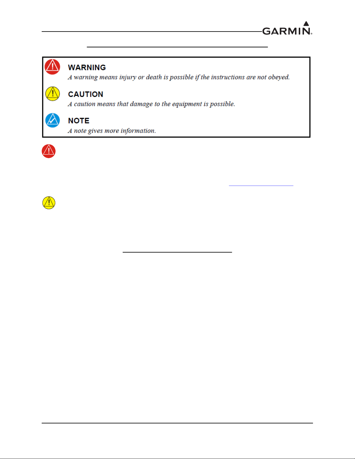
DEFINITIONS OF WARNINGS, CAUTIONS, AND NOTES
WARNING
This product, its packaging, and its components contain chemicals known to the State of
California to cause cancer, birth defects, or reproductive harm. This Notice is being
provided in accordance with California's Proposition 65. If you have any questions or
would like additional information, please refer to our web site at www.garmin.com/prop65
CAUTION
The front bezel, keypad, and display can be cleaned with a microfiber cloth or with a soft
cotton cloth dampened with clean water. DO NOT use any chemical cleaning agents.
Care should be taken to avoid scratching the surface of the display.
.
SOFTWARE LICENSE AGREEMENT
BY USING THE DEVICE, COMPONENT OR SYSTEM MANUFACTURED OR SOLD BY GARMIN
(“THE GARMIN PRODUCT”), YOU AGREE TO BE BOUND BY THE TERMS AND CONDITIONS
OF THE FOLLOWING SOFTWARE LICENSE AGREEMENT. PLEASE READ THIS AGREEMENT
CAREFULLY. Garmin Ltd. and its subsidiaries (“Garmin”) grants you a limited license to use the
software embedded in the Garmin Product (the “Software”) in binary executable form in the normal
operation of the Garmin Product. Title, ownership rights, and intellectual property rights in and to the
Software remain with Garmin and/or its third-party providers. You acknowledge that the Software is the
property of Garmin and/or its third-party providers and is protected under the United States of America
copyright laws and international copyright treaties. You further acknowledge that the structure,
organization, and code of the Software are valuable trade secrets of Garmin and/or its third-party providers
and that the Software in source code form remains a valuable trade secret of Garmin and/or its third-party
providers. You agree not to reproduce, decompile, disassemble, modify, reverse assemble, reverse
engineer, or reduce to human readable form the Software or any part thereof or create any derivative works
based on the Software. You agree not to export or re-export the Software to any country in violation of the
export control laws of the United States of America.
190-01553-00 GTR 200/200B Installation Manual
Rev. P Page ii

TABLE OF CONTENTS
PARAGRAPH PAGE
Section 1 General Description ...........................................................................1-1
1.1 Introduction...................................................................................................................... 1-1
1.2 Equipment Description .................................................................................................... 1-1
1.3 Technical Specifications .................................................................................................. 1-2
1.4 Certification ..................................................................................................................... 1-5
1.5 Reference Documents ...................................................................................................... 1-5
Section 2 Installation Overview.........................................................................2-1
2.1 Introduction...................................................................................................................... 2-1
2.2 Unit Configurations ......................................................................................................... 2-1
2.3 Available Accessories...................................................................................................... 2-1
2.4 Installation Considerations .............................................................................................. 2-2
2.5 Antenna Considerations................................................................................................... 2-3
2.6 Mounting Considerations................................................................................................. 2-5
2.7 Cabling and Wiring.......................................................................................................... 2-5
2.8 Air Circulation and Cooling ............................................................................................ 2-7
2.9 Compass Safe Distance.................................................................................................... 2-7
Section 3 Installation Procedures ......................................................................3-1
3.1 Unpacking the unit........................................................................................................... 3-1
3.2 Wiring Harness Installation ............................................................................................. 3-1
3.3 Backshell Assembly......................................................................................................... 3-2
3.4 Mounting Requirements .................................................................................................. 3-2
3.5 Antenna Installation and Connections ............................................................................. 3-3
3.6 Post Installation Configuration and Checkout Procedures .............................................. 3-4
3.7 Unit Software................................................................................................................. 3-20
3.8 Disabling Bluetooth® .................................................................................................... 3-23
3.9 Continued Airworthiness ............................................................................................... 3-23
Section 4 Connector Pinout Information..........................................................4-1
4.1 Pin Function List.............................................................................................................. 4-1
4.2 Power ............................................................................................................................... 4-2
4.3 Lighting Bus .................................................................................................................... 4-2
4.4 CAN Bus.......................................................................................................................... 4-3
4.5 Unit ID ............................................................................................................................. 4-3
4.6 Serial Data – RS-232 ....................................................................................................... 4-4
4.7 MIC Audio....................................................................................................................... 4-4
4.8 Aux Mono Audio ............................................................................................................. 4-5
4.9 Headset Audio.................................................................................................................. 4-5
4.10 Music Inputs .................................................................................................................. 4-5
190-01553-00 GTR 200/200B Installation Manual
Rev. P Page iii

PARAGRAPH PAGE
4.11 Receiver Audio .............................................................................................................. 4-6
4.12 Pilot/Copilot PTT Inputs................................................................................................ 4-6
4.13 TX Interlock................................................................................................................... 4-6
4.14 Discrete Inputs ............................................................................................................... 4-7
Appendix A Shield Block Connector Installation Instructions .....................A-1
A.1 Shield Block Installation Parts....................................................................................... A-1
A.2 Shield Termination Technique – Method A.1 (Standard) ............................................. A-3
A.3 Shield Termination Technique - Method A.2 (Daisy Chain) ........................................ A-7
A.4 Shield Termination – Method B.1 (Quick Term) .......................................................... A-7
A.5 Shield Termination-Method B.2 (Daisy Chain-Quick Term)........................................ A-9
A.6 Daisy Chain between Methods A and B ...................................................................... A-10
A.7 Splicing Signal Wires .................................................................................................. A-10
Appendix B Serial Interface Specifications..................................................... B-1
B.1 Electrical Interface ..........................................................................................................B-1
B.2 Message Formats.............................................................................................................B-1
Appendix C Outline and Installation Drawings .............................................C-1
Appendix D Interconnect Examples ................................................................D-1
190-01553-00 GTR 200/200B Installation Manual
Rev. P Page iv

LIST OF FIGURES
FIGURE PAGE
Section 1 General Description ...........................................................................1-1
Section 2 Installation Overview.........................................................................2-1
Figure 2-1 CAN Bus Configuration...................................................................................... 2-6
Section 3 Installation Procedures ......................................................................3-1
Figure 3-1 GTR 200/200B Front Panel ................................................................................ 3-4
Figure 3-2 Configuration Mode Home Page ........................................................................ 3-5
Figure 3-3 COM Setup Page................................................................................................. 3-7
Figure 3-4 ICS Sidetone Selection........................................................................................ 3-7
Figure 3-5 MON Swap Selection.......................................................................................... 3-8
Figure 3-6 Audio Setup Page (AUX and Music Disabled) .................................................. 3-9
Figure 3-7 Audio Setup Page (AUX and Music Enabled).................................................... 3-9
Figure 3-8 Softkey Setup Page ........................................................................................... 3-10
Figure 3-9 Discrete Setup Page .......................................................................................... 3-11
Figure 3-10 Lighting Setup Page ........................................................................................ 3-12
Figure 3-11 Lighting Graph................................................................................................ 3-13
Figure 3-12 RS-232 Status Page......................................................................................... 3-13
Figure 3-13 Headset Tests Page.......................................................................................... 3-14
Figure 3-14 COM Tests Page ............................................................................................. 3-15
Figure 3-15 Audio Tests Page ............................................................................................ 3-16
Figure 3-16 About Page...................................................................................................... 3-20
Figure 3-17 Software Update Page..................................................................................... 3-20
Figure 3-18 Micro SD Insertion.......................................................................................... 3-21
Figure 3-19 Software Update Page - Scanning Card.......................................................... 3-21
Figure 3-20 Software Update Page - No Update Found..................................................... 3-22
Figure 3-21 Software Update Page - Update Software?..................................................... 3-22
Figure 3-22 Software Update Page - Preparing Update...................................................... 3-22
Figure 3-23 Software Update Page - Unit Will Reboot...................................................... 3-22
Section 4 Connector Pinout Information..........................................................4-1
Figure 4-1 J2001 Looking at rear of unit.............................................................................. 4-1
Figure 4-2 CAN Bus Termination for GTR 200/200B......................................................... 4-3
Appendix A Shield Block Connector Installation Instructions.....................A-1
Figure A-1 Shield Block Install onto a Backshell .............................................................. A-2
Figure A-2 Method A.1 for Shield Termination................................................................. A-3
Figure A-3 Insulation/Contact Clearance ........................................................................... A-5
Figure A-4 Method A.2 (Daisy Chain) for Shield Termination ......................................... A-7
190-01553-00 GTR 200/200B Installation Manual
Rev. P Page v

FIGURE PAGE
Figure A-5 Method B.1 (Quick Term) for Shield Termination.......................................... A-8
Figure A-6 Method B.2 (Daisy Chain-Quick Term) for Shield Termination..................... A-9
Figure A-7 Daisy Chain between Methods A and B ........................................................ A-10
Figure A-8 D-Sub Spliced Signal Wire illustration.......................................................... A-11
Appendix B Serial Interface Specifications ....................................................B-1
Appendix C Outline and Installation Drawings .............................................C-1
Figure C-1 GTR 200/200B Outline Drawing .......................................................................C-1
Figure C-2 GTR 200/200B Assembly Drawing ...................................................................C-2
Figure C-3 GTR 200/200B Installation Drawing .................................................................C-3
Figure C-4 GTR 200/200B Panel Cutout Drawing ..............................................................C-4
Appendix D Interconnect Examples ................................................................D-1
Figure D-1 GTR 200/200B Interconnect Example Notes ................................................... D-1
Figure D-2 GTR 200/200B- Power & Ground/Intercom/GDU 37X/46X CAN
Bus Interconnect Example .................................................................................................... D-2
Figure D-3 GTR 200/200B- Power & Ground/Intercom/GDU 37X RS-232
Interconnect Example ........................................................................................................... D-3
Figure D-4 GTR 200/200B- Power & Ground/GMA 240/GNS 430/aera 79X
Interconnect Example ........................................................................................................... D-4
Figure D-5 GTR 200/200B- Mono Audio/Remote Mount Jack Interconnect Example...... D-5
Figure D-6 GTR 200/200B CAN Bus Interconnect Drawing ............................................. D-6
Figure D-7 Dual GTR 200/200B200/200B GMA 240 Interconnect Drawing .................... D-7
Figure D-8 LEMO Jack Interconnect Drawing ................................................................... D-8
Figure D-9 GTR 200/200B - J2001 Connector Layout ....................................................... D-9
190-01553-00 GTR 200/200B Installation Manual
Rev. P Page vi

LIST OF TABLES
TABLE PAGE
Section 1 General Description ...........................................................................1-1
Table 1-1 Available Units..................................................................................................... 1-1
Table 1-2 Physical Characteristics........................................................................................ 1-2
Table 1-3 General Specifications.......................................................................................... 1-2
Table 1-4 Display Specifications.......................................................................................... 1-3
Table 1-5 COM Transmitter Specifications.......................................................................... 1-3
Table 1-6 COM Receiver Specifications .............................................................................. 1-4
Table 1-7 FCC Grant of Equipment Authorization .............................................................. 1-5
Table 1-8 Reference Documents........................................................................................... 1-5
Section 2 Installation Overview.........................................................................2-1
Table 2-1 Catalog Part Numbers .......................................................................................... 2-1
Table 2-2 Standard Kit Accessories...................................................................................... 2-1
Table 2-3 Contents of Connector Kit (011-03240-00), see Figure C-2................................ 2-2
Table 2-4 Optional Accessories............................................................................................ 2-2
Section 3 Installation Procedures ......................................................................3-1
Table 3-1 Recommended Crimp Tools (or Equivalent) ....................................................... 3-1
Table 3-2 Socket Contact Part Numbers............................................................................... 3-1
Table 3-3 Configuration Default Settings............................................................................. 3-6
Table 3-4 COM Setup Page Selections................................................................................. 3-7
Table 3-5 Audio Setup Page Selections................................................................................ 3-9
Table 3-6 Softkey Setup Page Selections ........................................................................... 3-10
Table 3-7 Discrete Setup Page Selections .......................................................................... 3-11
Table 3-8 Lighting Setup Page Selections.......................................................................... 3-12
Table 3-9 Audio Tests Source Selections ........................................................................... 3-16
Table 3-10 Discrete Inputs.................................................................................................. 3-17
Table 3-11 TX Interlock Connections ................................................................................ 3-18
Section 4 Connector Pinout Information..........................................................4-1
Table 4-1 J2001 Connector................................................................................................... 4-1
Appendix A Shield Block Connector Installation Instructions ....................A-1
Table A-1 Parts not supplied for a Shield Block Installation (Figure A-1)......................... A-1
Table A-2 Shielded Cable Preparations for Garmin Connectors......................................... A-3
Table A-3 Shielded Cable Preparations – (Quick Term)..................................................... A-9
Appendix B Serial Interface Specifications .................................................... B-1
Appendix C Outline and Installation Drawings ............................................C-1
Appendix D Interconnect Examples ...............................................................D-1
190-01553-00 GTR 200/200B Installation Manual
Rev. P Page vii

1 GENERAL DESCRIPTION
1.1 Introduction
This manual is intended to provide mechanical and electrical information for use in the planning and
design of an installation of the GTR 200/200B into an aircraft. This manual is not a substitute for an
approved airframe-specific maintenance manual, installation design drawing, or complete installation data
package. Attempting to install equipment by reference to this manual alone and without first planning or
designing an installation specific to your aircraft may compromise your safety and is not recommended.
1.2 Equipment Description
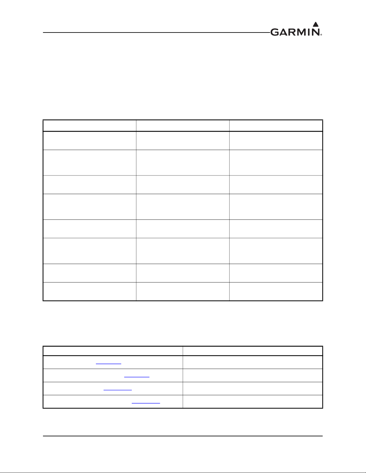
Table 1-1 Available Units
Model Part Number
GTR 200
with Serial Number Prefix 2QQ
GTR 200
with Serial Number Prefix 5JC
GTR 200B
with Serial Number Prefix 5JD
GTR 200B FAA-PMA
with Serial Number Prefix 5JD
TX Power
(Watt)
011-02980-00 10 N/A Yes
011-02980-10 10 N/A Yes
011-02980-20 10 N/A Yes
011-02980-40 10 N/A Yes
8.33 KHz
Spacing
CAUTION
The GTR 200/200B has a display that is coated with a special anti-reflective coating that
is very sensitive to waxes and abrasive cleaners. CLEANERS CONTAINING AMMONIA
WILL HARM THE ANTI-REFLECTIVE COATING. It is very important to clean the
display using a clean, lint-free cloth and an eyeglass lens cleaner that is specified as safe
for anti-reflective coatings.
CAUTION
The use of ground-based cellular telephones while aircraft are airborne is prohibited by
FCC rules. Due to potential interference with onboard systems, the use of ground-based
cell phones while the aircraft is on the ground is subject to FAA regulation 14 CFR §91.21.
FCC regulation 47 CFR §22.925 prohibits airborne operation of ground-based cellular
telephones installed in or carried aboard aircraft. Ground-based cellular telephones must
not be operated while aircraft are off the ground. When any aircraft leaves the ground, all
ground-based cellular telephones on board that aircraft must be turned off. Ground-based
cell phones that are on, even in a monitoring state, can disrupt GPS/SBAS performance.
25 KHz
Spacing
NOTE
All screen shots used in this document are current at the time of publication. Screen shots
are intended to provide visual reference only. All information depicted in screen shots,
including software file names, versions, and part numbers, is subject to change and may
not be up to date.
190-01553-00 GTR 200/200B Installation Manual
Rev. P Page 1-1
1.3 Technical Specifications
1.3.1 Physical Characteristics
Table 1-2 Physical Characteristics
Characteristics Specifications
Bezel Height 1.35 in (34.29 mm)
Bezel Width 6.25 in (158.8 mm)
Rack Height (Dimple-to-Dimple) 1.375 in (34.93 mm)
Rack Width 6.30 in (160.02 mm)
Depth Behind Panel with Connectors (Measured
from face of aircraft panel to rear of connector
backshells)
GTR 200/200B Weight (Unit Only) 1.38 lbs (0.63 kg)
9.39 in (238.51 mm)
GTR 200/200B (Installed with rack and
connectors)
1.3.2 General Specifications
Table 1-3 General Specifications
Characteristics Specifications
Operating Temperature Range -20C to +55C
Humidity 95% non-condensing
Altitude Range -1,500 ft to 55,000 ft
Input Voltage Range 14/28 VDC
0.6 A, Typical when receiving
Current Draw* at 14 VDC
Current Draw* at 28 VDC
3.0 A, Typical when transmitting
7.50 A Maximum, 90% modulated into 3:1 VSWR
and 11V power input voltage
0.30 A, Typical when receiving
1.40 A, Typical when transmitting
3.75 A Maximum, 90% modulated into 3:1 VSWR
and 22V power input voltage
1.95 lbs (0.88 kg)
Bluetooth 3.00 Compliant, allows music and cell
phone calls. Bluetooth supports HFP (including
HFP v1.6 Wide Band Speech mode), A2DP, and
Bluetooth Connectivity (GTR 200B only)
*The specified current draw is with the display backlight set to 100%
AVRCP.
The GTR 200B stores 10 paired devices and
overwrites the least recently connected device
when a new device is paired. Only 1 Bluetooth
connection allowed at one time.
190-01553-00 GTR 200/200B Installation Manual
Rev. P Page 1-2

1.3.3 Display
The display on the GTR is a sunlight readable LCD display.
Table 1-4 Display Specifications
Characteristics Specifications
Display Size
Active Area
Resolution 200 x 33 pixels
Viewing Angle
Width: 3.46” (88.0mm)
Height: 0.843” (21.4mm)
Width: 2.95” (74.98mm)
Height: 0.486” (12.36mm)
Left: 45
Right: 45°
Up: 10
Down: 30
1.3.4 COM Specifications
The GTR 200/200B transmitter meets the requirements of RTCA DO-186B section 2.3 for a class 4
transmitter.
Table 1-5 COM Transmitter Specifications
Characteristics Specifications
Two inputs, standard carbon or dynamic mic with integrated
Microphone Input
preamp. The GTR 200/200B provides a 150 Ω AC input impedance
and supplies the microphone with an 11 V bias through 470 Ω +/5%.
85% with 150 to 1500 mVRMS microphone input at 1000 Hz.
Modulation Capability
Modulation
Frequency Range 118.000 to 136.975 MHz, 25 kHz channel spacing
Frequency Tolerance +/-5 ppm from -20°C to +55°C
Output Power 10 Watts carrier minimum
Duty Cycle 20%
Carrier Noise Level At least 35 dB (SNR).
Stuck Mic Time-Out 35 seconds time-out, reverts to receive
Demodulated Audio Distortion
Range can be extended from 20 mVrms to 2500 mVrms with mic
gain adjustment.
AM Double sided Emission Designator:
6K00A3E (118 - 136.975 MHz)
Less than 25% distortion when the transmitter is at 85% modulation
at 350 to 2500 Hz
190-01553-00 GTR 200/200B Installation Manual
Rev. P Page 1-3
The GTR 200/200B receiver meets the requirements of RTCA DO-186B section 2.2 for a class C receiver.
Table 1-6 COM Receiver Specifications
Characteristics Specifications
Frequency Range 118.000 to 136.975 MHz, 25 kHz channel spacing
Headset Audio Output 60 mW minimum into a 150 Ω load
Audio Response Less than 6 dB of variation between 350 and 2500 Hz.
Audio Distortion Less than 25% at rated output power
Sensitivity
Squelch Automatic squelch with manual override
SINAD greater than 6 dB when the RF level is -107 dBm
with 30% modulation
1.3.5 License Requirements
The Telecommunications Act of 1996, effective February 8, 1996, provides the FCC discretion to
eliminate radio station license requirements for aircraft and ships. GTR installations must comply with
current transmitter licensing requirements. In the US, to find out the specific details on whether a particular
installation is exempt from licensing, please visit the FCC web site http://wireless.fcc.gov/aviation
. If an
aircraft license is required, make application for a license on FCC form 404, Application for Aircraft Radio
Station License. The FCC also has a fax-on-demand service to provide forms by fax. Outside the US,
contact the responsible telecommunication authority. The GTR owner accepts all responsibility for
obtaining the proper licensing before using the transceiver. The maximum transmitting power, modulation
identification, and frequency band information may be required for licensing and are detailed in
Section 1.3.4
.
1.3.6 Aircraft Radio
An aircraft radio station license is not required when operating in U.S. airspace, but may be required when
operating internationally.
190-01553-00 GTR 200/200B Installation Manual
Rev. P Page 1-4

1.4 Certification
The GTR 200/200B does not have TSO authorization.
The GTR 200B Part Number 011-02980-40 has FAA-PMA
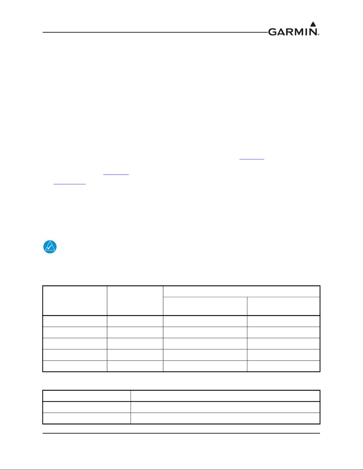
1.4.1 FCC Grant of Equipment Authorization
Table 1-7 FCC Grant of Equipment Authorization
Model FCC ID IC ID
GTR 200 IPH-02115-01 1792A-02115-01
IPH-02115-01 1792A-02115-01
GTR 200B
Contains QOQWT32I
(for the Bluetooth module)
Contains 5123A-BGTWT32I
(for the Bluetooth module)
1.5 Reference Documents
The following publications are sources of additional information for installing the GTR 200/200B. Before
installing the GTR 200/200B, the installer should read all referenced materials along with the manual.
Table 1-8 Reference Documents
Part Number Document
190-01553-01 GTR 200/200B Pilot’s Guide
190-01553-00 GTR 200/200B Installation Manual
Rev. P Page 1-5
2 INSTALLATION OVERVIEW
2.1 Introduction
Careful planning and consideration of the suggestions in this section are required to achieve the desired
performance and reliability from the GTR 200/200B. The guidance of FAA advisory circulars AC 43.131B and AC 43.13-2B, where applicable, may be found useful for making retro-fit installations that comply
with FAA regulations.
2.2 Unit Configurations
Table 2-1 Catalog Part Numbers
Model Catalog Part Number Unit Only Part Number
GTR 200 Unit Only,
Serial Number Prefix 2QQ
GTR 200 Standard,
(includes items in Table 2-2)
Serial Number Prefix 2QQ
GTR 200 Unit Only,
Serial Number Prefix 5JC
GTR 200 Standard,
(includes items in Table 2-2)
Serial Number Prefix 5JC
GTR 200B,
Serial Number Prefix 5JD
GTR 200B Standard,
(includes items in Table 2-2)
Serial Number Prefix 5JD
GTR 200B FAA-PMA,
Serial Number Prefix 5JD
GTR 200B Standard FAA-PMA,
Serial Number Prefix 5JD
010-01087-00 011-02980-00
010-01087-01 011-02980-00
010-01087-10 011-02980-10
010-01087-11 011-02980-10
010-01087-20 011-02980-20
010-01087-21 011-02980-20
010-01087-40 011-02980-40
010-01087-41 011-02980-40
2.3 Available Accessories
2.3.1 Standard Accessories
Table 2-2 Standard Kit Accessories
Item Part Number
Connector Kit (see Table 2-3) 011-03240-00
Connector Kit FAA-PMA (see Table 2-3) 011-03240-01
Installation Rack (see Figure C-2) 115-01878-00
Installation Rack FAA-PMA (see Figure C-2) 115-01878-02 (ordered as 011-03240-10)
190-01553-00 GTR 200/200B Installation Manual
Rev. P Page 2-1

Table 2-3 Contents of Connector Kits (011-03240-00/-01), see Figure C-2
Item Part Number Quantity
Backshell w/Hardware, 37 pin 011-00950-03 1
Connector Plate 115-01879-00 1
Ring Terminal 117-00147-01 1
Single Coax Connector Plate Adapter 125-00165-00 1
Pan Head Phillips Screw 8-32 x .312 211-60209-09 6
Flat Head Phillips Screw 4-40 x .250 211-63234-08 4
Flat Head Phillips Screw 4-40 x .375 211-63234-10 4
Split Lock Washer, size 8 212-00018-04 6
Shoulder Washer 212-00022-00 1
Flat Washer #4 212-00024-04 1
Flat Washer, Inside Diameter 0.195”, Outside Diameter 0.354” 212-20065-00 6
Alignment Pin, Shoulder #4-40 233-00087-00 1
Male/Female BNC Connector 330-00053-01 1
37 Pin D-Sub Crimp Socket Connector 330-00625-37 1
Crimp Socket Contact, Size 20, 20-24 AWG 336-00022-02 37
2.3.2 Optional Accessories
Table 2-4 Optional Accessories
Item Part Number
4 GB Micro SD Card (w/SD adapter) 010-10683-05
2.4 Installation Considerations
2.4.1 COM Antenna
A COM Antenna that meets TSO-C37( ) and C38( ) or TSO-C169( ), 50W, vertically polarized with
coaxial cable is recommended but not provided.
2.4.2 Installation Materials
The GTR 200/200B is intended for use with the standard aviation accessories. The following items are
required for installation, but not supplied:
• Wire (MIL-W-22759/16 or equivalent)
• Shielded Wire (MIL-C-27500 or equivalent)
• Hardware - #6-32 x 100° Flat Head SS Screw [(MS24693, AN507R or other approved fastener)
(6 ea.)] and #6-32 Self-Locking Nut [MS21042 or other approved fastener (6 ea.)]
• Push/Pull (that can be manually reset) Circuit Breaker
• Tie Wraps or Lacing Cord
• Ring Terminals (for grounding)
• Coaxial Cable (RG-400, RG-142B or coaxial cable with 50 Ω impedance meeting applicable
aviation regulations should be used.
190-01553-00 GTR 200/200B Installation Manual
Rev. P Page 2-2

2.5 Antenna Considerations
This section contains mounting location considerations for the antennas required for the GTR 200/200B.
For mounting the COM antenna, refer to the aircraft manufacturer’s data.
2.5.1 COM Antenna Location
The GTR 200/200B COM antenna should be well removed from all projections, engines and propellers.
The ground plane surface directly below the antenna should be a flat plane over as large an area as possible
(18 inch square, minimum). The antenna should be mounted a minimum of six feet from any DME or
other COM antennas, and four feet from any ADF sense antennas. The COM antenna should also be
mounted as far as practical from the ELT antenna. Some ELTs have exhibited re-radiation problems that
cause interference with other radios, including GPS. This can happen when the COM (GTR 200/200B or
any other COM) is transmitting on certain frequencies such as 121.15 or 121.175 MHz, which may cause
the ELT output circuit to oscillate from the signal coming in on the ELT antenna coax.
If simultaneous use of two COM transceivers is desired (split-COM or simul-comm), the COM antennas
should be spaced for maximum isolation. A configuration of one topside antenna and one bottom side
antenna is recommended. The GTR 200/200B requires a transmit interlock.
Simultaneous COM performance varies significantly across installations and is affected by both the
isolation between the COM antennas and the separation of the tuned frequencies. Each installation should
be individually examined to determine the expected performance of simultaneous COM.
CAUTION
If the COM antennas are mounted less than six feet apart with a direct line of sight
between the antennas the non-transmitting radio could be damaged when the other radio
transmits. An example of direct line of sight is both antennas mounted on the bottom or
top surface of the aircraft. For metallic aircraft one antenna should be mounted on the
bottom close to the front and the other on the top of the aircraft close to the tail such that
the aircraft structure is between the two antennas. For composite aircraft additional
shielding may be needed between top and bottom mounted COM antennas.
NOTE
The GTR 200/200B COM antenna should be installed at least 20 cm from the front panel
of the GTR 200/200B unit.
190-01553-00 GTR 200/200B Installation Manual
Rev. P Page 2-3

NOTE
Canadian installations are required to meet Industry Canada specifications for maximum
radiation as documented in Radio Specifications Standard 102 (RSS-102). For more
information about RF exposure and related Canadian regulatory compliance, contact:
Manager, Radio Equipment Standards
Industry Canada
365 Laurier Avenue
Ottawa, Ontario
K1A 0C8
In accordance with Canadian Radio Specifications Standard 102 (RSS 102), an RF safety
separation distance of 26 cm from the antenna should be maintained for an RF field
2
strength exposure to persons of less than the 10W/m
Under Industry Canada regulations, this radio transmitter may only operate using an
antenna of a type and maximum (or lesser) gain approved for the transmitter by Industry
Canada. To reduce potential radio interference to other users, the antenna type and its
gain should be so chosen that the equivalent isotropically radiated power (e.i.r.p.) is not
more than that necessary for successful communication.
The GTR 200/200B has been approved by Industry Canada to operate with the antenna
types listed below. Antenna types not included in this list, having a gain greater than the
maximum gain indicated for that type, are strictly prohibited for use with this device.
A COM Antenna that meets TSO-C37( ) and C38( ) or TSO-C169( ), 50W, vertically
polarized. Maximum gain of 1 dBi with an impedance of 50 ohms.
occupational safety limit.
2.5.2 Interference of GPS
On some installations, VHF COM transceivers, Emergency Locator Transmitter (ELT) antennas, and
Direction Finder (DF) receiver antennas can re-radiate to the GPS antenna. Placement of the GPS antenna
relative to a COM transceiver and COM antenna (including the GTR/ COM antenna), ELT antenna, and
DF receiver antenna is critical.
Use the following guidelines, in addition to others in this document, when locating the GTR 200/200B and
its antenna.
• Locate the GTR 200/200B as far as possible from all GPS antennas.
• Locate the COM antenna as far as possible from all GPS antennas.
If a COM is found to be radiating, the following can be done:
• Replace or clean VHF COM rack connector to ensure good coax ground.
• Place a grounding brace between the GTR 200/200B and ground.
• Shield the GTR 200/200B wiring harness.
190-01553-00 GTR 200/200B Installation Manual
Rev. P Page 2-4

2.6 Mounting Considerations
The GTR 200/200B is designed to mount in the avionics stack in the aircraft instrument panel within view
and reach of the pilot. The primary unit location should minimize pilot head movement when transitioning
between looking outside of the cockpit and viewing/operating the GTR 200/200B. The location should be
such that the GTR 200/200B unit is not blocked by the glare shield on top, or by the throttles, control yoke,
etc. on the bottom. If aircraft has a throw-over yoke, be sure the yoke does not interfere with the GTR 200/
200B.
2.7 Cabling and Wiring
Refer to the interconnect examples in Appendix D for wire gauge guidance.
Use wire and cable meeting the applicable aviation regulation. When routing wire and cable, observe the
following precautions:
• Keep as short and as direct as possible
• Avoid sharp bends
• Avoid routing near power sources (e.g. 400 Hz generators, trim motors, etc.) or near power for
fluorescent lighting
• Do not route cable near high voltage sources
CAUTION
To avoid damage to the GTR 200/200B, take precautions to prevent Electro-Static
Discharge (ESD) when handling the GTR 200/200B, connectors, and associated wiring.
ESD damage can be prevented by touching an object that is of the same electrical
potential as the GTR 200/200B before handling the GTR 200/200B itself.
2.7.1 Noise
As audio signals are routed to and from the GTR 200/200B (Headset, Microphone, Music, AUX), care
must be taken to minimize effects from coupled interference and ground loops.
Interference can be coupled into interconnecting cables when they are routed near large AC electric fields,
AC voltage sources, and pulse equipment (strobes, spark plugs, magnetos, EL displays, CRTs, etc).
Interference can also couple into interconnecting cables by magnetic induction when they are routed near
large AC current-carrying conductors or switched DC equipment (heaters, solenoids, fans, autopilot
servos, etc).
Ground loops are created when there is more than one path in which return currents can flow, or when
signal returns share the same path as large currents from other equipment. These large currents create
differences in ground potential between various equipment operating in the aircraft. These differences in
potential can produce an additive effect at audio signal inputs.
The GTR 200/200B audio inputs may detect the desired input signal plus an unwanted component injected
by ground differentials, a common cause of alternator-related noise. This can be minimized by isolating all
audio jacks from ground.
Terminating shields at just one end (single-point grounding) eliminates another potential ground loop
injection point. The single-point grounding method is critical for the installation of various avionics that
produce and process audio signals. Single-point, in this context, means that the various pieces of
equipment share a single common ground connection back to the airframe.
Good aircraft electrical/charging system ground bonding is important.
The wiring diagrams and accompanying notes in this manual should be followed closely to minimize noise
effects.
190-01553-00 GTR 200/200B Installation Manual
Rev. P Page 2-5

2.7.2 CAN Bus Considerations
R
L
R
L
CAN Bus Backbone
CAN HI
CAN LOW
(Node #1)
LRU
(Node #2)
LRU
(Node #3)
LRU
(Node #n)
LRU
Node Length
0.3 meter max.
The CAN (controller area network) bus (Figure 2-1) is an interface format used to establish
communication between several LRUs in the G3X system. Each end of the CAN bus “backbone” must be
terminated. Each node length (distance from CAN bus backbone to each LRU) must be 0.3 meter or less
in length (keeping the node lengths as short as practicable is recommended). There is no minimum node
length.
A GTR 200/200B can be connected in a G3X system that uses a GDU 37X or GDU 46X with CAN bus or
RS232, the CAN bus is preferred.
NOTE
Use only two CAN bus terminations per installation (even if provided more than two from
associated G3X installation kits). Using less than or more than two terminations (one at
each end of the backbone) will make the CAN bus unusable or unreliable.
Figure 2-1 CAN Bus Configuration
The following items should be considered when installing/removing/replacing LRU’s on the CAN bus:
1. CAN bus node connections must be made on the connector of each LRU that connects to the CAN
bus, do not tie CAN bus nodes from individual LRUs together into a single connection point.
2. Keep all node lengths as short as practicable, and allow only one ‘lengthy’ node if possible.
NOTE
The 120 Ω termination resistors described in the preceding paragraphs are “built-in” to
the termination method shown in Figure D-2
resistor to terminate the CAN bus.
. Do not install a separate “discrete” 120 Ω
190-01553-00 GTR 200/200B Installation Manual
Rev. P Page 2-6

2.8 Air Circulation and Cooling
The GTR 200/200B unit meets all requirements without external cooling. However, as with all electronic
equipment, lower operating temperatures extends equipment life. Reducing the operating temperature by
15° to 20°C (27° to 36°F) reduces the mean time between failures (MTBF).
Units tightly packed in the avionics stack heat each other through radiation, convection, and sometimes by
direct conduction. Even a single unit operates at a much higher temperature in still air than in moving air.
Fans or some other means of moving the air around electronic equipment are usually a worthwhile
investment.
2.9 Compass Safe Distance
After reconfiguring the avionics in the cockpit panel, if the unit is mounted less than 12 inches from the
compass, recalibrate the compass and make the necessary changes for noting correction data.
190-01553-00 GTR 200/200B Installation Manual
Rev. P Page 2-7
3 INSTALLATION PROCEDURES
3.1 Unpacking the unit
Carefully unpack the equipment and make a visual inspection of the unit for evidence of damage incurred
during shipment. If the unit is damaged, notify the carrier and file a claim. To justify a claim, save the
original shipping container and all packing materials. Do not return the unit to Garmin until the carrier has
authorized the claim.
Retain the original shipping containers for storage. If the original containers are not available, a separate
cardboard container should be prepared that is large enough to accommodate sufficient packing material to
prevent movement.
3.2 Wiring Harness Installation
Allow adequate space for installation of cables and connectors. The installer shall supply and fabricate all
cables. All electrical connections to the GTR 200/200B are made through one 37-pin D-sub standard
density connector (P2001) and one BNC connector for the antenna (P2002). Section 4
characteristics of all input and output signals. Required connectors and associated hardware are supplied
with the connector kit (Table 2-3
See Appendix D
for examples of interconnect wiring diagrams. Construct the actual harnesses in
).
accordance with the aircraft manufacturer authorized interconnect standards. After the cable assemblies
are made, route the wiring bundle as appropriate. Use cable ties to provide strain relief for the coax and
cable assemblies
.
The connector uses crimp contacts. Table 3-1 identifies crimp tools required to ensure consistent, reliable
crimp contact connections for the D-sub connector P2001. Table 3-2 identifies the contacts used for
P2001.
defines the electrical
NOTE
Check wiring connections for errors before connecting to the GTR 200/200B. Incorrect
wiring could cause internal component damage.
Table 3-1 Recommended Crimp Tools (or Equivalent)
Manufacturer
Military P/N M22520/2-01 M22520/2-08 M81969/1-02
Positronic 9507-0-0-0 9502-5-0-0 4711-2-0-0
AMP 601966-1 601966-5 91067-2
Daniels AFM8 K13-1 M81969/1-02
Astro 61517 615724 M81969/1-02
Hand Crimping
Tool
Positioner
Table 3-2 Socket Contact Part Numbers
Supplier 20-24 AWG Socket Contact Part Number
Garmin Part Number 336-00022-02
Military Part Number M39029/63-368
20 – 24 AWG (P2001)
Extraction Tool
Insertion/
190-01553-00 GTR 200/200B Installation Manual
Rev. P Page 3-1

3.3 Backshell Assembly
Refer to Appendix A for backshell and Shield Block ground assembly instructions.
3.4 Mounting Requirements
3.4.1 Rack Installation
Use the dimensions shown in Appendix C
the GTR 200/200B unit mounting rack itself as a template for drilling the mounting holes.
1. Figure C-1
rectangular hole (or gap between units) in the instrument panel per Figure C-4
of the rack should be flush with, or extend slightly beyond the finished face of the aircraft panel.
shows outline dimensions for the avionics rack for the unit. Install the rack in a
to prepare the mounting holes for the unit. You may also use
. The lower-front lip
NOTE
If the front lip of the mounting rack is behind the surface of the aircraft panel, the unit
connectors may not fully engage. See Figure C-4
screw heads or other obstructions prevent the unit from fully engaging in the rack.
Exercise caution when installing the rack into the instrument panel. Deformation of the
rack may make it difficult to install and remove the unit.
2. Install the rack in the aircraft panel using six #6-32 flat head screws. The screws are inserted from
the inside through the holes in the sides of the rack.
3. Follow the steps listed in Figure C-3
3.4.2 Unit Insertion and Removal
It may be necessary to insert the hex drive tool into the access hole and rotate the drive tool
counterclockwise until it completely stops in order to ensure correct position of the retention mechanism
prior to placing the unit in the rack. The unit is installed in the rack by sliding it straight in until it stops,
about 3/8 inch short of the final position. A 3/32-inch hex drive tool is then inserted into the access hole at
the bottom of the unit face. Rotate the hex tool clockwise while pressing on the bezel until the unit is
firmly seated in the rack.
to attach the backplate to the rack.
for more information. Ensure that no
To remove the unit from the rack, insert the hex drive tool into the access hole on the unit face. Rotate
counterclockwise until the unit is forced out about 3/8 inch and the hex drive tool completely stops. This
will allow the unit to be freely pulled from the rack.
Be sure not to over tighten the unit into the rack. The application of hex drive tool torque exceeding
15 in-lbs can damage the locking mechanism.
190-01553-00 GTR 200/200B Installation Manual
Rev. P Page 3-2

3.5 Antenna Installation and Connections
The GTR 200/200B requires a standard 50 vertically polarized antenna. Follow the antenna
manufacturer’s installation instructions for mounting the antenna.
The antenna should be mounted on a metal surface or a ground plane with a minimum area of 18 inches x
18 inches. Refer to Section 2.5.1
3.5.1 Antenna Coaxial Cable Installation
The antenna coax cable should be made of RG-142B, RG-400 or a comparable quality 50 coax. Follow
the BNC connector manufacturer’s instructions for cable preparation/connector installation.
Check that there is ample space for the cabling and mating connectors. Avoid sharp bends in the antenna
cable, and routing near aircraft control cables. Route the COM antenna cable as far as possible away from
any GPS antenna cables.
Check for insertion loss and Voltage Standing Wave Ratio (VSWR). VSWR should be checked with an
in-line type VSWR/wattmeter inserted in the coaxial transmission line between the transceiver and the
antenna. The VSWR meter should be inserted as close to the transceiver as possible. When rack and
harness buildup is performed in the shop, the coax termination may be provisioned by using a 6-inch inline BNC connection. This would be an acceptable place to insert the VSWR meter. Any problem with
the antenna installation is most likely seen as high reflected power. A VSWR of 3:1 may result in up to a
50% loss in transmit power. VSWR at the low, mid and high end of the tuning range should be less than
3:1, for best performance VSWR should be less than 2:1. A high VSWR decreases the amount of power
radiated by the antenna and increases power supply current and heat dissipated by the radio when the radio
is transmitting.
for installation location considerations.
190-01553-00 GTR 200/200B Installation Manual
Rev. P Page 3-3
3.6 Post Installation Configuration and Checkout Procedures
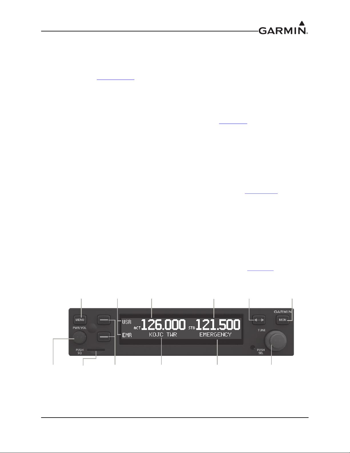
Menu
Button
Softkeys 1 (top)
and 2 (bottom)
Power/
Volume/
Squelch
Knob
Softkey
Labels
Active
Frequency
Active
Frequency
Identifier
Standby
Frequency
Standby
Frequency
Identifier
Frequency
Transfer
Key
LARGE and SMALL
Knobs
Monitor
Standby
Frequency
Micro SD
Card Slot
3.6.1 System Configuration Overview
This section contains checks to ensure the system is properly installed and functioning correctly as well as
instructions for configuring the GTR 200/200B to the specific installation. Follow the instructions in
Section 3.6.2 through Section 3.6.7.1
procedures.
3.6.2 Mounting, Wiring, and Power Checks
Verify that all cables are properly secured and shields are connected to the shield block of the connectors.
Check the movement of the flight and engine controls to verify there is no interference between the cabling
and control systems. Ensure that all wiring is installed as described in Section 2.7
Prior to powering up the unit, the wiring harness must be checked for proper connections to the aircraft
systems and other avionics equipment. Point to point continuity must be checked to expose any faults such
as shorting to ground. Any faults or discrepancies must be corrected before proceeding.
After accomplishing a continuity check, perform power and ground checks to verify proper power
distribution to the GTR 200/200B. Any faults or discrepancies should be corrected at this time. Remove
power from the aircraft upon completion of the harness checkout.
The GTR 200/200B can be installed after completion of the continuity and power checks. The GTR 200/
200B should be installed into the rack and secured appropriately, as described in Section 3.4.2
200/200B must be connected to the wiring harness and antenna.
3.6.3 Configuration Mode
in order to complete all post installation configuration and checkout
.
. The GTR
The configuration pages shown in this section reflect main software version 2.40 or later. Some
differences in operation may be observed when comparing the information in this manual to later software
versions. Refer to Figure 3-1 to identify knobs, buttons, and softkeys used in the configuration procedures.
Configuration mode is used to configure the unit settings for each specific installation. To access
configuration mode, remove power from the unit. With the unit turned off, press and hold the SMALL
Knob and apply power by turning the Power/Volume/Squelch Knob clockwise. Release the SMALL
Knob when the display activates, the Config Mode Home page will be displayed (Figure 3-2
).
Figure 3-1 GTR 200/200B Front Panel
190-01553-00 GTR 200/200B Installation Manual
Rev. P Page 3-4

3.6.4 Configuration Pages
The first page displayed in configuration mode (see Section 3.6.3
(Figure 3-2). From the Configuration Mode Home page, turn the LARGE Knob to select the desired
subpage then press the SMALL Knob to display the subpage.
Figure 3-2 Configuration Mode Home Page
There are eight subpages available in configuration mode, each of these subpages is described in the
following sections:
• COM SETUP - See Section 3.6.4.2
• AUDIO SETUP - See Section 3.6.4.3
• SOFTKEY SETUP - See Section 3.6.4.4
• DISCRETE SETUP - See Section 3.6.4.5
• LIGHTING SETUP - See Section 3.6.4.6
• RS-232 STATUS - See Section 3.6.4.7
• HEADSET TESTS - See Section 3.6.5.1
• COM TESTS - See Section 3.6.5.2
• AUDIO TESTS - See Section 3.6.5.3
) is the Configuration Mode Home page
190-01553-00 GTR 200/200B Installation Manual
Rev. P Page 3-5

3.6.4.1 Default Settings
Table 3-3 lists the default values for the configuration mode settings.
Table 3-3 Configuration Default Settings
Page Setting Default Note
SIDETONE 5
COM SETUP
AUDIO SETUP
SOFTKEY SETUP
DISCRETE SETUP
MIC GAIN 5
RF SQLCH 0
INTERCOM ENABLED YES
RECEIVER OUT GAIN 100%
AUX 1 SQUELCH 30%
AUX 1 VOLUME 50%
AUX 1 MUTE (MUSIC) NO
AUX 2 SQUELCH 30%
AUX 2 VOLUME 50%
AUX 2 MUTE (MUSIC) NO
PILOT ON RIGHT SIDE NO
KEY 1 USER LIST
KEY 2 TUNE EMERGENCY
DISC 1 PILOT ICS KEY
DISC 2 COPILOT ICS KEY
LIGHTING SOURCE SENSOR
TIME CONSTANT 5.0/0.2
First value is photocell default;
Second value is lighting bus
default
N/A for photocell
LIGHTING SETUP
MIN INPUT LEVEL 10%/21%
MIN BRIGHTNESS 10%/10%
MAX INPUT LEVEL 90%/86%
MAX BRIGHTNESS 100%
OFF THRESHOLD 21%
OFF HYSTERESIS 0.1%
BUTTON OFFSET 10%
190-01553-00 GTR 200/200B Installation Manual
Rev. P Page 3-6
 Loading...