

Garmin GFC 500 Maintenance Manual

190-02291-01 2017 Revision 1
GFC 500
Autopilot with Envelope Stability
And Protection
Part 23 AML STC Maintenance Manual
Includes Instructions for Continued Airworthiness
for STC SA01866WI

GFC 500 Autopilot with ESP Part 23 AML STC Maintenance Manual Page i
190-02291-01 Revision 1
© Copyright 2017
Garmin Ltd. or its subsidiaries
All Rights Reserved
Except as expressly provided herein, no part of this manual may be reproduced, copied, transmitted,
disseminated, downloaded or stored in any storage medium, for any purpose without the express prior
written consent of Garmin. Garmin hereby grants permission to download a single copy of this manual
and of any revision to this manual onto a hard drive or other electronic storage medium to be viewed and
to print one copy of this manual or of any revision hereto, provided that such electronic or printed copy of
this manual or revision must contain the complete text of this copyright notice and provided further that
any unauthorized commercial distribution of this manual or any revision hereto is strictly prohibited.
Garmin International, Inc.
1200 E. 151st Street
Olathe, KS 66062 USA
Telephone: 913.397.8200
www.garmin.com
Garmin (Europe) Ltd.
Liberty House, Bulls Copse Road
Hounsdown Business Park
Southampton, SO40 9RB, UK
Phone: +44 (0) 23 8052 4000
Fax: +44 (0) 23 8052 4004
Garmin AT, Inc.
2345 Turner Rd., SE
Salem, OR 97302 USA
Telephone: 503.581.8101
RECORD OF REVISIONS
Revision
Revision Date
Description
1
12/19/17
Initial Release
DOCUMENT PAGINATION
Section
Pagination
Table of Contents
i – vi
Section 1
1 – 4
Section 2
5 – 9
Section 3
10 – 10
Section 4
11 – 17
Section 5
18 – 20
Section 6
21 – 23
Section 7
24 – 24
Section 8
25 – 25
Section 9
26 – 38

GFC 500 Autopilot with ESP Part 23 AML STC Maintenance Manual Page ii
190-02291-01 Revision 1
INFORMATION SUBJECT TO EXPORT CONTROL LAWS
This document may contain information which is subject to the Export Administration
Regulations (“EAR”) issued by the United States Department of Commerce (15 CFR, Chapter
VII Subchapter C) and which may not be exported, released or disclosed to foreign nationals
inside or outside the United States without first obtaining an export license. A violation of the
EAR may be subject to a penalty of up to 10 years imprisonment and a fine of up to $1,000,000
under section 2410 of the Export Administration Act of the 1979. The preceding statement is
required to be included on any and all reproductions in whole or in part of this manual.
This product, its packaging, and its components contain chemicals known to the State of
California to cause cancer, birth defects, or reproductive harm. This Notice is being provided in
accordance with California's Proposition 65. If you have any questions or would like additional
information, please refer to our web site at www.garmin.com/prop65.
Perchlorate Material – special handling may apply, Refer to www.dtsc.ca.gov./hazardouswaste/
perchlorate.
All screen shots used in this document are current at the time of publication. Screen shots are
intended to provide visual reference only. All information depicted in screen shots, including
software file names, versions and part numbers, is subject to change and may not be up to
date.
WARNING
IMPORTANT
WARNING

GFC 500 Autopilot with ESP Part 23 AML STC Maintenance Manual Page iii
190-02291-01 Revision 1
TABLE OF CONTENTS
PARAGRAPH PAGE
1. INTRODUCTION ................................................................................................................. 1
1.1 Content, Scope, Purpose .............................................................................................. 1
1.2 Applicability ................................................................................................................... 1
1.3 Organization .................................................................................................................. 1
1.4 Definitions/Abbreviations ............................................................................................... 2
1.5 Units of Measure ........................................................................................................... 3
1.6 Reference Publications ................................................................................................. 3
1.7 Revision and Distribution ............................................................................................... 4
1.8 Garmin Technical Support ............................................................................................. 4
2. SYSTEM DESCRIPTION .................................................................................................... 5
2.1 Equipment Descriptions ................................................................................................ 5
2.2 GFC 500 Interface Summary ......................................................................................... 6
2.3 Power Requirements ..................................................................................................... 7
2.4 Electrical Bonding ......................................................................................................... 7
3. CONTROL AND OPERATION ...........................................................................................10
3.1 GMC 507 ......................................................................................................................10
3.2 Autopilot Disconnect/Trim Interrupt Switch ...................................................................10
3.3 Trim Switch ..................................................................................................................10
3.4 Go Around (GA) Switch ................................................................................................10
4. INSTRUCTIONS FOR CONTINUED AIRWORTHINESS ...................................................11
4.1 Airworthiness Limitations ..............................................................................................11
4.2 Servicing Information....................................................................................................12
4.3 Maintenance Intervals ..................................................................................................14
4.4 Visual Inspection ..........................................................................................................15
4.5 Electrical Bonding Test .................................................................................................16
4.6 Disconnect Tone and Sonalert Test .............................................................................17
5. TROUBLESHOOTING .......................................................................................................18
5.1 GFC 500 Failure Messages..........................................................................................18
5.2 General Troubleshooting ..............................................................................................18
5.3 GFC 500 Interconnect Drawings ................................ ..................................................20
5.4 Connector Layout .........................................................................................................20
6. EQUIPMENT REMOVAL & INSTALLATION .....................................................................21
6.1 GMC 507 ......................................................................................................................21
6.2 GSA 28 Servos ............................................................................................................23
7. GFC 500 LRU REPLACEMENT/CONFIGURATION & TESTING ......................................24

GFC 500 Autopilot with ESP Part 23 AML STC Maintenance Manual Page iv
190-02291-01 Revision 1
7.1 GMC 507 ......................................................................................................................24
7.2 GSA 28 Servo ..............................................................................................................24
8. GFC 500 SOFTWARE LOAD AND CONFIGURATION PROCEDURES ...........................25
8.1 GMC 507 and GSA 28 Software Loading .....................................................................25
8.2 GFC 500 System Configuration ....................................................................................25
9. GFC 500 RETURN TO SERVICE PROCEDURE ...............................................................26
9.1 Yaw Offset and Pitch/Roll Offset Calibration ................................................................26
9.2 Pre-Flight Test (PFT)....................................................................................................26
9.3 Normal Mode Tests ................................................................................................ ......27

GFC 500 Autopilot with ESP Part 23 AML STC Maintenance Manual Page v
190-02291-01 Revision 1
LIST OF ILLUSTRATIONS
FIGURE PAGE
Figure 2-1 – GMC 507 ............................................................................................................... 5
Figure 2-2 – GFC 500 System Overview .................................................................................... 6
Figure 2-3 – Electrical Bonding Preparation – Nut Plate ............................................................. 8
Figure 2-4 – Electrical Bonding Preparation – Bolt/Nut Joint ...................................................... 8
Figure 2-5 – Electrical Bonding Preparation – Terminal Lug ....................................................... 9
Figure 6-1 – GMC 507 Installation with rack ..............................................................................22
Figure 6-2 – GMC 507 Installation without rack .........................................................................22

GFC 500 Autopilot with ESP Part 23 AML STC Maintenance Manual Page vi
190-02291-01 Revision 1
LIST OF TABLES
TABLE ................................................................................................................................ PAGE
Table 1-1 – Required Documents............................................................................................... 3
Table 1-2 – Garmin Reference Documents ................................................................................ 3
Table 1-3 – Other Reference Documents ................................................................................... 3
Table 2-1 – Power Requirements ............................................................................................... 7
Table 2-2 – Electrical Bonding ................................................................................................... 8
Table 4-1 – Maintenance Intervals ............................................................................................14
Table 4-2 – Visual Inspection Procedure ...................................................................................15
Table 4-3 – Lightning Strike Inspection Procedure ....................................................................16

GFC 500 Autopilot with ESP Part 23 AML STC Maintenance Manual Page 1
190-02291-01 Revision 1
1. Introduction
1.1 Content, Scope, Purpose
This document provides maintenance instructions and Instructions for Continued Airworthiness
(ICA) for the GFC 500 Autopilot with Envelope Stability and Protection as installed under
Supplemental Type Certificate (STC) SA01866WI.
1.2 Applicability
This document applies to all Part 23 aircraft equipped with the GFC 500 installed under AML
STC SA01866WI.
Modification of an aircraft by STC SA01866WI obligates the aircraft operator to include the
maintenance information provided by this document in the operator’s Aircraft Maintenance
Manual and the operator’s Aircraft Scheduled Maintenance Program.
1.3 Organization
The following outline briefly describes the organization of this manual:
Section 2: System Description
Provides a complete description of the type design change associated with installing the GFC
500 Autopilot. Also provides an interface summary, power requirements, and instructions on
electrical bonding.
Section 3: Control and Operation
Provides brief instructions on controls and operation.
Section 4: Instructions for Continued Airworthiness
Provides maintenance instructions for continued airworthiness of the GFC 500 Autopilot.
Section 5: Troubleshooting
Provides troubleshooting information to aid in diagnosing and resolving potential problems with
the GFC 500 Autopilot.
Section 6: Equipment Removal & Replacement
Gives instructions for the removal and replacement of GFC 500 Autopilot equipment.
Section 7: GFC 500 LRU Replacement/Configuration & Testing
Gives instructions for loading software, configuring, and testing of GFC 500 Autopilot
equipment.
Section 8: GFC 500 Software Load and Configuration Procedures
Gives instructions for loading software and configuring the GFC 500 Autopilot.
Section 9: GFC 500 Return to Service Procedure
Specifies return-to-service procedures to be performed upon completion of maintenance of the
GFC 500 Autopilot.

GFC 500 Autopilot with ESP Part 23 AML STC Maintenance Manual Page 2
190-02291-01 Revision 1
1.4 Definitions/Abbreviations
ADI: Attitude Director Indicator
AML: Approved Model List
ARP: Aerospace Recommended Practice
ASTM: American Society for Testing and Materials
CDI: Course Deviation Indicator
CFR: Code of Federal Regulations
CWS: Control Wheel Steering
DDM: Difference in Depth of Modulation
DTK: Desired Track
ESP: Electronic Stability and Protection
FAA: Federal Aviation Administration
GPS: Global Positioning System
ICA: Instructions for Continued Airworthiness
ILS: Instrument Landing System
LRU: Line Replaceable Unit
OBS: Omni-Bearing Selector
PFT: Pre-Flight Test
SAE: Society of Automotive Engineers
STC: Supplemental Type Certificate
VOR: VHF Omnidirectional Radio

GFC 500 Autopilot with ESP Part 23 AML STC Maintenance Manual Page 3
190-02291-01 Revision 1
1.5 Units of Measure
Unless otherwise stated, all units of measure are English units.
1.6 Reference Publications
All of the documents listed in Table 1-1 and Table 1-2 are available for download through the
Dealer Resource Center section of the Garmin web site. Refer to Section 1.7 for details.
The documents listed in Table 1-1 are required by this maintenance manual to perform
maintenance on the GFC 500 Autopilot. It is the responsibility of the owner/operator to ensure
that the latest versions of these documents are used during operation, servicing or maintenance
of the airplane. Note: There is a model-specific installation manual addendum for each model
covered. Each has a different dash number. Refer to the Master Drawing List 005-01264-00 for
applicability.
Table 1-1 – Required Documents
Document Number
Title
005-01264-00
Master Drawing List GFC 500 Autopilot with Electronic Stability and Protection Part 23
AML STC
190-02291-00
GFC 500 Autopilot with Electronic Stability and Protection Part 23 AML STC Installation
Manual
190-02291-XX
GFC 500 Autopilot with Electronic Stability and Protection Part 23 AML STC ModelSpecific Installation Manual Addendum
190-01112-12
G5 Electronic Flight Instrument Pilot’s Guide for Certified Aircraft
The documents listed in Table 1-2 are recommended to be available during the performance of
maintenance activities.
Table 1-2 – Garmin Reference Documents
Document Number
Title
190-01112-11
Garmin G5 Electronic Flight Instrument Part 23 AML STC Maintenance Manual
190-02291-00
Garmin GFC 500 Autopilot with Electronic Stability and Protection Part 23 AML STC
Installation Manual
190-01112-12
G5 Electronic Flight Instrument Pilot’s Guide for Certified Aircraft
Table 1-3 – Other Reference Documents
Document Number
Title
AC 43.13-1B
FAA Advisory Circular, Acceptable Methods, Techniques, and Practices
– Aircraft Inspection and Repair
AC 43.13-2B
FAA Advisory Circular, Acceptable Methods, Techniques, and Practices
– Aircraft Alterations
SAE ARP1870
Aerospace Systems Electrical Bonding and Grounding for Electromagnetic Compatibility
and Safety
SAE AS4461
Assembly and Soldering Criteria for High Quality/High Reliability Soldered Wire and
Cable Termination in Aerospace Vehicles
SAE AS50881
Wiring, Aerospace Vehicle
ASTM F 2490-05
Standard Guide for Aircraft Electrical Load and Power Source Capacity Analysis

GFC 500 Autopilot with ESP Part 23 AML STC Maintenance Manual Page 4
190-02291-01 Revision 1
1.7 Revision and Distribution
This document is required for maintaining the continued airworthiness of the GFC 500 Autopilot.
When this document is revised, every page will be revised to indicate current revision level.
Garmin Dealers may obtain the latest revision of this document on the Garmin Dealer Resource
Center website.
Owner/operators may obtain the latest revision of this document from the https://fly.garmin.com/
Support page, or by contacting a Garmin dealer, contacting Garmin Product Support at 913397-8200, toll free 866-739-5687, or using around the world contact information on
https://fly.garmin.com/.
A Garmin Service Bulletin describing the revision to this document will be sent to Garmin
dealers if the revision is determined to be significant.
1.8 Garmin Technical Support
For technical support contact, Garmin Aviation Product Support at 913-397-8200 (toll free 866739-5687) or by using the around the world contact information on www.flygarmin.com.

GFC 500 Autopilot with ESP Part 23 AML STC Maintenance Manual Page 5
190-02291-01 Revision 1
2. System Description
2.1 Equipment Descriptions
2.1.1 GMC 507 Autopilot Mode Controller
The GMC 507 Autopilot mode controller is shown in Figure 2 1. The switches on the front panel
of the GMC 507 provide inputs to the G5 instrument and GSA 28 servos for flight director
computations. The GMC 507 also contains some of the system monitoring and audio functions
for the system.
Refer to the G5 Electronic Flight Instrument Pilot’s Guide for Certified Aircraft, 190-01112-12 for
operational characteristics of the system.
Figure 2-1 – GMC 507
2.1.2 GSA 28 Servo
The GSA 28 is a smart servo. The autopilot, trim and ESP algorithms are performed by the
servo. The motor in the GSA 28 servo is a brushless DC motor. This brushless DC motor has
an inherent safety feature in that it cannot drive by itself and requires software commutation to
run. The brushless DC motor also has a lower backdrive friction than brushed motor or
steppers motors. The GSA 28 is limited to a maximum of 60 in-lbs of torque.
GFC 500 Autopilot systems may have up to three servos (pitch, roll, and pitch trim). The pitch
trim servo is optional and may not be available on all airframes. Most installations will use bridle
cables attached to the primary flight control cables using clamps. New servo brackets, servo
bridle cables, and clamps are installed by this STC.
2.1.3 Audio Output
The GMC 507 provides an analog audio output to an audio panel, plus an active low output to
drive an external aural alert device (e.g. sonalert). The analog audio can be interfaced to any
audio panel that has an unswitched and unmuted analog audio input. If no existing audio panel
is interfaced, a sonalert is required.

GFC 500 Autopilot with ESP Part 23 AML STC Maintenance Manual Page 6
190-02291-01 Revision 1
2.2 GFC 500 Interface Summary
The following figure provides a high-level summary of the GFC 500 autopilot system. The G5 is
required to be installed by STC SA01818WI. The minimum system requires the G5 in the
attitude indicator position.
Figure 2-2 – GFC 500 System Overview

GFC 500 Autopilot with ESP Part 23 AML STC Maintenance Manual Page 7
190-02291-01 Revision 1
2.3 Power Requirements
Table 2-1 below summarizes the power requirements for the GFC 500 LRUs.
Table 2-1 – Power Requirements
LRU
Characteristics
Specifications
GMC 507
Average Current Draw @ 14 VDC
0.11 A
Max Current Draw @ 14 VDC
0.20 A
Average Current Draw @ 28 VDC
0.06 A
Max Current Draw @ 28 VDC
0.11 A
GSA 28
Average Current Draw @ 14 VDC
0.36 A
Max Current Draw @ 14 VDC
1.80 A
Average Current Draw @ 28 VDC
0.20 A
Max Current Draw @ 28 VDC
0.90 A
2.4 Electrical Bonding
For the purposes of this STC, aircraft ground reference definitions vary according to airframe
type as defined in Table 2-2. Refer to the periodic test and reconditioned resistance values
corresponding to these ground reference definitions when performing the equipment bonding
tests in Section 4.5.
The periodic test value is the value allowed during the bonding checks specified in Section 4.5.
The reconditioned value is the value allowed on initial installation or if the bond must be
reworked if the periodic test value is exceeded.
Refer to SAE ARP 1870 Section 5 when surface preparation is required to achieve electrical
bond.
GFC 500 Autopilot with ESP Part 23 AML STC Maintenance Manual Page 8
190-02291-01 Revision 1
Table 2-2 – Electrical Bonding
Aircraft Type
Ground Reference
Maximum Resistance Between GFC
500 Equipment Chassis and Ground
Reference (mΩ)
Periodic Test
Reconditioned
Metallic Airframe
Nearby metal structure for servos
or
Instrument panel for GMC 507
10.0
2.5
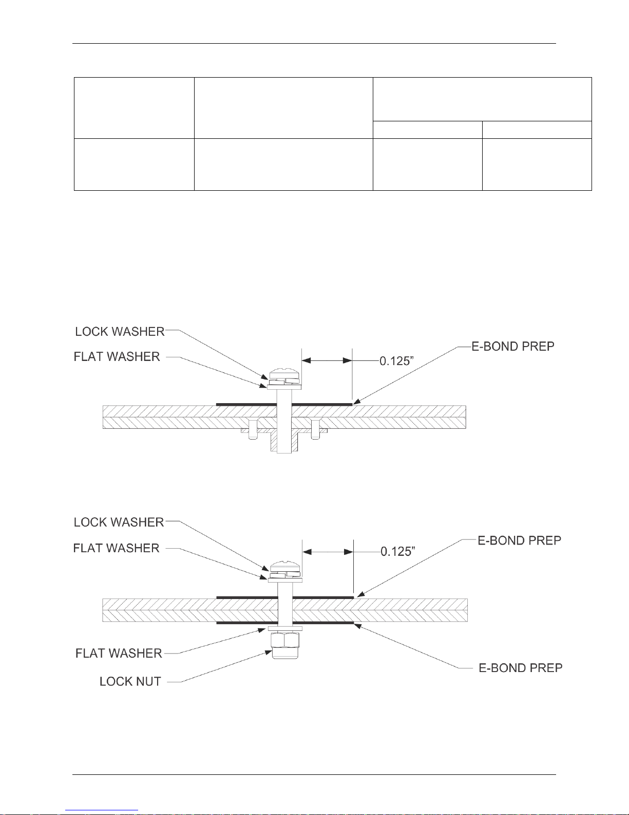
2.4.1 Consideration for Untreated or Bare Dissimilar Metals
The correct material finish is important when mating untreated or bare dissimilar metals.
Materials should be galvanically compatible. When corrosion protection is removed to make an
electrical bond any exposed area after the bond is completed should be protected again.
Additional guidance can be found in SAE ARP 1870 Section 5. Typical electrical bonding
preparation examples are shown in Figure 2-3, Figure 2-4, and Figure 2-5.
Figure 2-3 – Electrical Bonding Preparation – Nut Plate
Figure 2-4 – Electrical Bonding Preparation – Bolt/Nut Joint
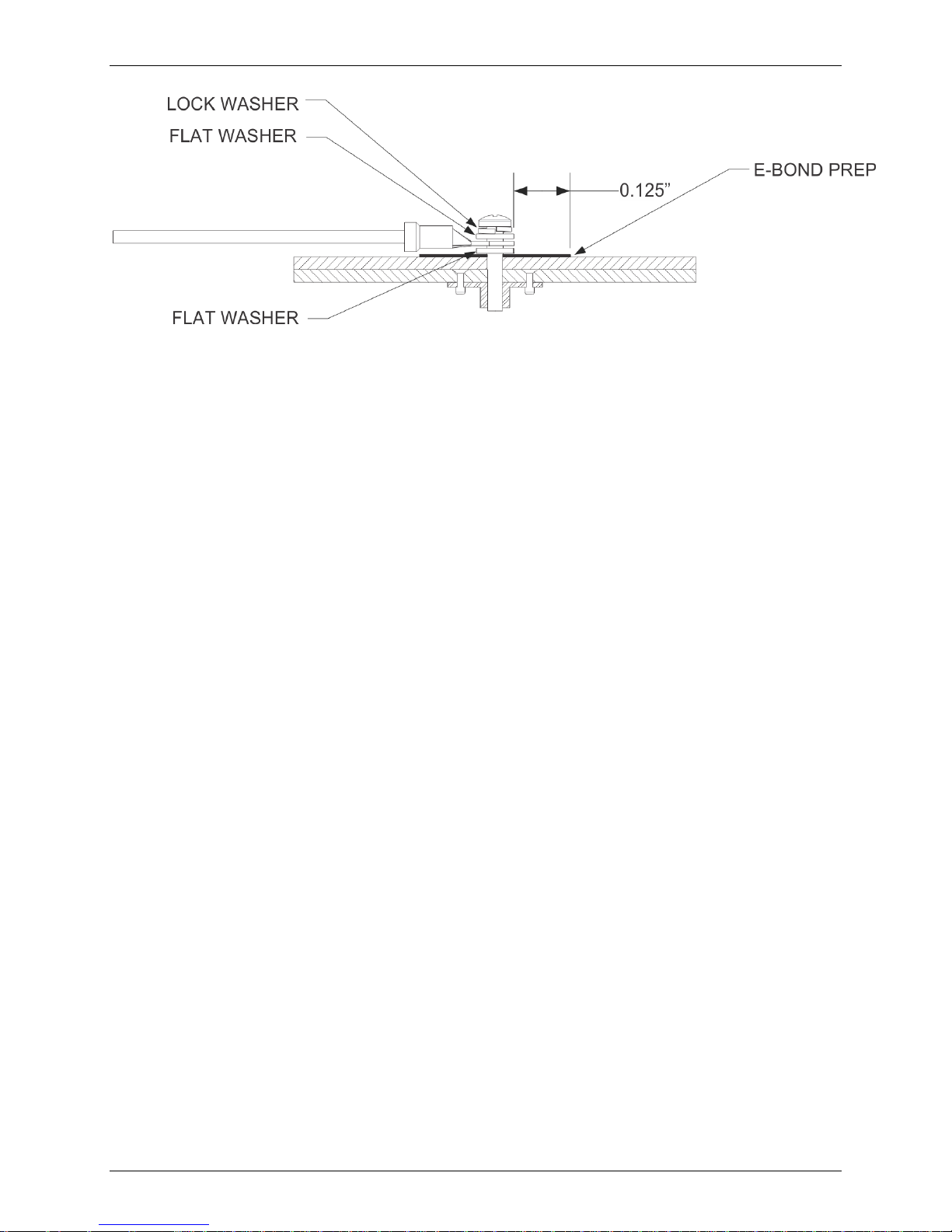
GFC 500 Autopilot with ESP Part 23 AML STC Maintenance Manual Page 9
190-02291-01 Revision 1
Figure 2-5 – Electrical Bonding Preparation – Terminal Lug
2.4.2 Preparation of Aluminum Surfaces
The following general procedure is recommended to prepare an aluminum surface for proper
electrical bonding.
1. Clean grounding location with solvent.
2. Remove non-conductive films or coatings from the grounding location.
3. Apply a chemical conversion coat such as Alodine 1200 to the bare metal.
4. Once the chemical conversion coat is dry, clean the area.
5. Install bonding equipment at grounding location.
6. After bond is complete, if any films or coatings were removed from the surface, reapply a
suitable film or coating to the surrounding area within 24 hours.
After satisfactory electrical bond is achieved, when it has been necessary to remove any highresistance protective coating, the area from which the coating has been removed should be
refinished with the same finish as is on the rest of the part within 24 hours. In cases where the
parts come in with certain areas spot-faced, or if there is no finish on the part (bare metal), apply
conformal coating over the bond joint and hardware per MIL-I-46058 or clear lacquer per TT-L20A in order to facilitate future inspection. Refer to the model specific Aircraft Maintenance
Manual or Standard Practices Manual for surface protection requirements applicable to affected
areas. The correct material finish is important when mating untreated or bare dissimilar metals.
They should be galvanically compatible. When corrosion protection is removed to make an
electrical bond, any exposed area after the bond is completed should be protected again.
Additional guidance can be found in SAE ARP 1870 Section 5.
For a more detailed procedure, refer to SAE ARP 1870 Sections 5.1 and 5.5.
 Loading...