

Garmin G500H, GDU 620 Reference Manual
G500H
Cockpit
Reference Guide

© 2011-2015 Garmin Ltd. or its subsidiaries. All rights reserved.
This manual reflects the operation of system software version 6.00 or later. Some differences in operation
may be observed when comparing the information in this manual to later software versions.
Garmin International, Inc., 1200 East 151st Street, Olathe, KS 66062, U.S.A.
Tel: 913.397.8200 Fax: 913.397.8282
Garmin AT, Inc., 2345 Turner Road SE, Salem, OR 97302, U.S.A. Tel: 503.391.3411 Fax 503.364.2138
Garmin (Europe) Ltd., Liberty House, Bulls Copse Road, Hounsdown Business Park, Southampton, SO40
9RB, U.K. Tel. +44 (0) 870 850 1243 Fax +44 (0) 238 052 4004
Garmin Corporation, No. 68, Jangshu 2nd Road, Shijr, Taipei County, Taiwan
Tel: 886.02.2642.9199 Fax: 886.02.2642.9099
www.garmin.com
At Garmin, we value your opinion. For comments about this guide, please e-mail:
Techpubs.Salem@garmin.com.
Except as expressly provided herein, no part of this manual may be reproduced, copied, transmitted,
disseminated, downloaded or stored in any storage medium, for any purpose without the express written
permission of Garmin. Garmin hereby grants permission to download a single copy of this manual and of
any revision to this manual onto a hard drive or other electronic storage medium to be viewed for personal
use, provided that such electronic or printed copy of this manual or revision must contain the complete text
of this copyright notice and provided further that any unauthorized commercial distribution of this manual
or any revision hereto is strictly prohibited.
Garmin®, GDU™ 620 are trademarks of Garmin Ltd. or its subsidiaries. FliteCharts®, and SafeTaxi® are
registered trademarks of Garmin Ltd. or its subsidiaries. These trademarks may not be used without the
express permission of Garmin.
NavData® is a registered trademark of Jeppesen, Inc.; SkyWatch® is a registered trademark of L-3
Communications; and XM® is a registered trademark of XM Satellite Radio, Inc.
AOPA Membership Publications Inc., and its related organizations (hereinafter collectively “AOPA”)
expressly disclaim all warranties, with respect to the AOPA information included in this data, express or
implied, including, but not limited to, the implied warranties of merchantability and fitness for a particular
purpose. The information is provided “as is” and AOPA does not warrant or make any representations
regarding its accuracy, reliability, or otherwise. Under no circumstances including negligence, shall AOPA
be liable for any incidental, special or consequential damages that result from the use or inability to use
the software or related documentation, even if AOPA or an AOPA authorized representative has been
advised of the possibility of such damages. User agrees not to sue AOPA and, to the maximum extent
allowed by law, to release and hold harmless AOPA from any causes of action, claims or losses related
to any actual or alleged inaccuracies in the information. Some jurisdictions do not allow the limitation or
exclusion of implied warranties or liability for incidental or consequential damages so the above limitations
or exclusions may not apply to you.
March 2015 Printed in the U.S.A.

i
G500H Cockpit Reference Guide
190-01150-03 Rev F
AVIATION LIMITED WARRANTY
All Garmin avionics products are warranted to be free from defects in materials or workmanship for: two
years from the date of purchase for new Remote-Mount and Panel-Mount products; one year from the
date of purchase for new portable products and any purchased newly-overhauled products; six months
for newly-overhauled products exchanged through a Garmin Authorized Service Center; and 90 days for
factory repaired or newly-overhauled products exchanged at Garmin in lieu of repair. Within the applicable
period, Garmin will, at its sole option, repair or replace any components that fail in normal use. Such repairs
or replacement will be made at no charge to the customer for parts or labor, provided that the customer
shall be responsible for any transportation cost. This warranty does not apply to: (i) cosmetic damage, such
as scratches, nicks and dents; (ii) consumable parts, such as batteries, unless product damage has occurred
due to a defect in materials or workmanship; (iii) damage caused by accident, abuse, misuse, water, flood,
fire, or other acts of nature or external causes; (iv) damage caused by service performed by anyone who is
not an authorized service provider of Garmin; or (v) damage to a product that has been modified or altered
without the written permission of Garmin. In addition, Garmin reserves the right to refuse warranty claims
against products or services that are obtained and/or used in contravention of the laws of any country.
THE WARRANTIES AND REMEDIES CONTAINED HEREIN ARE EXCLUSIVE AND IN LIEU OF ALL OTHER
WARRANTIES, WHETHER EXPRESS, IMPLIED OR STATUTORY, INCLUDING ANY LIABILITY ARISING UNDER
ANY WARRANTY OF MERCHANTABILITY OR FITNESS FOR A PARTICULAR PURPOSE, STATUTORY OR
OTHERWISE. THIS WARRANTY GIVES YOU SPECIFIC LEGAL RIGHTS, WHICH MAY VARY FROM STATE TO
STATE.
IN NO EVENT SHALL GARMIN BE LIABLE FOR ANY INCIDENTAL, SPECIAL, INDIRECT OR CONSEQUENTIAL
DAMAGES, WHETHER RESULTING FROM THE USE, MISUSE OR INABILITY TO USE THE PRODUCT OR
FROM DEFECTS IN THE PRODUCT. SOME STATES DO NOT ALLOW THE EXCLUSION OF INCIDENTAL OR
CONSEQUENTIAL DAMAGES, SO THE ABOVE LIMITATIONS MAY NOT APPLY TO YOU.
Garmin retains the exclusive right to repair or replace (with a new or newly-overhauled replacement
product) the product or software or offer a full refund of the purchase price at its sole discretion. SUCH
REMEDY SHALL BE YOUR SOLE AND EXCLUSIVE REMEDY FOR ANY BREACH OF WARRANTY.
Online Auction Purchases: Products purchased through online auctions are not eligible for warranty
coverage. Online auction confirmations are not accepted for warranty verification. To obtain warranty
service, an original or copy of the sales receipt from the original retailer is required. Garmin will not replace
missing components from any package purchased through an online auction.
International Purchases: A separate warranty may be provided by international distributors for devices
purchased outside the United States depending on the country. If applicable, this warranty is provided
by the local in-country distributor and this distributor provides local service for your device. Distributor
warranties are only valid in the area of intended distribution. Devices purchased in the United States or
Canada must be returned to the Garmin service center in the United Kingdom, the United States, Canada,
or Taiwan for service.
To obtain warranty service, contact your local Garmin Authorized Service Center. For assistance in locating a
Service Center near you, visit the Garmin web site at http://www.garmin.com or contact Garmin Customer
Service at 866.739.5687.

ii G500H Cockpit Reference Guide
190-01150-03 Rev F
WARNINGS, CAUTIONS, AND NOTES
WARNINGS, CAUTIONS, AND NOTES
Warnings, Cautions, & Notes
WARNING:
Navigation and terrain separation must NOT be predicated
upon the use of the terrain function. The G500H Terrain Proximity feature
is NOT intended to be used as a primary reference for terrain avoidance
and does not relieve the pilot from the responsibility of being aware of
surroundings during flight. The Terrain Proximity feature is only to be used
as an aid for terrain avoidance and is not certified for use in applications
requiring a certified terrain awareness warning system. Terrain data is
obtained from third party sources. Garmin is not able to independently
verify the accuracy of the terrain data.
WARNING:
The displayed minimum safe altitudes (MSAs) are only advisory
in nature and should not be relied upon as the sole source of obstacle and
terrain avoidance information. Always refer to current aeronautical charts
for appropriate minimum clearance altitudes.
WARNING:
The Garmin G500H has a very high degree of functional
integrity. However, the pilot must recognize that providing monitoring and/
or self-test capability for all conceivable system failures is not practical.
Although unlikely, it may be possible for erroneous operation to occur
without a fault indication shown by the G500H. It is thus the responsibility
of the pilot to detect such an occurrence by means of cross-checking with
all redundant or correlated information available in the cockpit.
WARNING:
The altitude calculated by GPS receivers is geometric height
above Mean Sea Level and could vary significantly from the altitude
displayed by pressure altimeters, such as the output from the GDC 74H
Air Data Computer, or other pressure altimeters in aircraft. GPS altitude
should never be used for vertical navigation. Always use pressure altitude
displayed by the G500H PFD or other pressure altimeters in aircraft.
WARNING:
Do not use outdated database information. Databases used
in the G500H system must be updated regularly in order to ensure that
the information remains current. Pilots using an outdated database do so
entirely at their own risk.

iii
G500H Cockpit Reference Guide
190-01150-03 Rev F
WARNINGS, CAUTIONS, AND NOTES
WARNINGS, CAUTIONS, AND NOTES
WARNING: Do not use basemap (land and water data) information for
primary navigation. Basemap data is intended only to supplement other
approved navigation data sources and should be considered as an aid to
enhance situational awareness.
WARNING:
Traffic information shown on the G500H Multi-Function Display
is provided as an aid in visually acquiring traffic. Pilots must maneuver
the aircraft based only upon ATC guidance or positive visual acquisition
of conflicting traffic.
WARNING: Do not use the indicated data link weather product age to
determine the age of the weather information shown by the data link
weather product. Due to time delays inherent in gathering and processing
weather data for data link transmission, the weather information shown by
the data link weather product may be significantly older than the indicated
weather product age.
WARNING: For safety reasons, G500H operational procedures must be
learned on the ground.
WARNING: To reduce the risk of unsafe operation, carefully review and
understand all aspects of the G500H Pilot’s Guide. Thoroughly practice basic
operation prior to actual use. During flight operations, carefully compare
indications from the G500H to all available navigation sources, including
the information from other NAVAIDs, visual sightings, charts, etc. For safety
purposes, always resolve any discrepancies before continuing navigation.
WARNING: Never use the G500H to attempt to penetrate a thunderstorm.
Both the FAA Advisory Circular, Subject: Thunderstorms, and the Airman’s
Information Manual (AIM) recommend avoiding “by at least 20 miles any
thunderstorm identified as severe or giving an intense radar echo”.
WARNING: Exceeding 200 deg/second in pitch or roll may invalidate AHRS
attitude provided to the G500H.

iv G500H Cockpit Reference Guide
190-01150-03 Rev F
WARNINGS, CAUTIONS, AND NOTES
WARNINGS, CAUTIONS, AND NOTES
WARNING: Because of anomalies in the earth’s magnetic field, operating
the G500H within the following areas could result in loss of reliable attitude
and heading indications. North of 65° North latitude between longitude
75° West and 120° West. An area North of 70° North latitude between
longitude 70° West and 128° West. An area of North of 70° North latitude
between longitude 85° East and 114° East. An area South of 55° South
latitude between longitude 120° East and 165° East.
WARNING: Do not use Terrain-HSVT information for primary terrain
avoidance. Terrain-HSVT is intended only to enhance situational awareness.
CAUTION: The United States government operates the Global Positioning
System and is solely responsible for its accuracy and maintenance. The
GPS system is subject to changes which could affect the accuracy and
performance of all GPS equipment. Portions of the Garmin G500H utilize
GPS as a precision electronic NAVigation AID (NAVAID). Therefore, as
with all NAVAIDs, information presented by the G500H can be misused or
misinterpreted and therefore, become unsafe.
CAUTION: The Garmin G500H does not contain any user-serviceable parts.
Repairs should only be made by an authorized Garmin service center.
Unauthorized repairs or modifications could void both the warranty and
pilot’s authority to operate this device under FAA/FCC regulations.
CAUTION: The G500H PFD and MFD displays use a lens coated with a
special anti-reflective coating that is very sensitive to skin oils, waxes, and
abrasive cleaners. CLEANERS CONTAINING AMMONIA WILL HARM THE
ANTI-REFLECTIVE COATING. It is very important to clean the lens using a
clean, lint-free cloth and an eyeglass lens cleaner that is specified as safe
for anti-reflective coatings.
CAUTION: FIS-B information is to be used for pilot planning
decisions and pilot near-term decisions focused on avoiding areas
of inclement weather that are beyond visual range or where poor
visibility precludes visual acquisition of inclement weather. FIS-B
weather and NAS status information may be used as follows:
- To promote pilot awareness of own ship location with respect to reported
weather, including hazardous meteorological conditions, NAS status indicators,
and enhance pilot planning decisions and pilot near-term decision-making.

v
G500H Cockpit Reference Guide
190-01150-03 Rev F
WARNINGS, CAUTIONS, AND NOTES
WARNINGS, CAUTIONS, AND NOTES
- To cue the pilot to communicate with the Air Traffic Control
controller, Flight Service Station specialist, operator dispatch, or
airline operations control center for general and mission critical
meteorological information, NAS status conditions, or both.
FIS-B information, including, weather information, NOTAMs, and TFR
areas, are intended for the sole purpose of assisting in long- and nearterm planning decision making. The system lacks sufficient resolution and
updating capability necessary for aerial maneuvering associated with
immediate decisions.
NOTE: Interference from GPS repeaters operating inside nearby hangars
can cause an intermittent loss of attitude and heading displays while the
aircraft is on the ground. Moving the aircraft more than 100 feet away
from the source of the interference should alleviate the condition.
NOTE: Do not rely solely upon data link services to provide Temporary Flight
Restriction (TFR) information. Always confirm TFR information through
official sources such as Flight Service Stations or Air Traffic Control.
NOTE: All visual depictions contained within this document, including
screen images of the G500H bezel displays, are subject to change and
may not reflect the most current G500H system. Depictions of equipment
may differ slightly from the actual equipment.
NOTE: This product, its packaging, and its components contain chemicals
known to the State of California to cause cancer, birth defects, or
reproductive harm. This notice is being provided in accordance with
California’s Proposition 65. If you have any questions or would like
additional information, please refer to our web site at www.garmin.com/
prop65.
NOTE: This device complies with part 15 of the FCC Rules. Operation is
subject to the following two conditions: (1) this device may not cause
harmful interference, and (2) this device must accept any interference
received, including interference that may cause undesired operation.
NOTE: Terrain data is not displayed when the aircraft latitude is greater
than 75° North or 60° South.

vi G500H Cockpit Reference Guide
190-01150-03 Rev F
NOTE: Terrain-HSVT is standard when the Synthetic Vision Technology
(SVT) option is installed. The HTAWS option will take precedence over
Terrain-HSVT.
NOTE: Do not use SafeTaxi or Chartview functions as the basis for ground
maneuvering. SafeTaxi and Chartview functions have not been qualified to
be used as an airport moving map display (AMMD). SafeTaxi and Chartview
are intended to improve pilot situational awareness during ground
operations should only be used by the flight crew to orient themselves on
the airport surface.
Record of Revisions
Part Number Revision Date Description
190-01150-03 A
B
C
D
E
F
Jan 2010
Mar 2010
Nov 2010
Aug 2011
Jan 2012
Mar 2015
Production Release
Updated speed tape markings.
Update to reflect v4.00 and v5.00
software functionality.
Update to reflect v6.00 software
functionality.
Minor edits.
Updates for SW Version 7.00.

vii
G500H Cockpit Reference Guide
190-01150-03 Rev F
TABLE OF CONTENTS
TABLE OF CONTENTS
Contents
Warnings, Cautions, & Notes ............................................................................ii
Introduction ...................................................................................................... 1
Primary Flight Display (PFD) ............................................................................. 2
Airspeed Tape .............................................................................................................................. 4
Altitude Tape ............................................................................................................................... 5
Barometric Pressure ..................................................................................................................... 5
Minimums Bug (Barometric or Radar Altimeter) ............................................................................ 6
Altitude Bug ................................................................................................................................ 8
Wind Vectors ............................................................................................................................... 9
Vertical Speed (V/S) ..................................................................................................................... 9
Vertical Deviation Indicator (VDI) ............................................................................................... 10
Temperature Display .................................................................................................................. 10
DME Indication .......................................................................................................................... 11
Clock/Timer ............................................................................................................................... 11
Attitude Indicator ...................................................................................................................... 12
Horizontal Situation Indicator (HSI): Aircraft Heading .................................................................. 13
Adjusting the Course Pointer ..................................................................................................... 14
HSI Bearing Pointers .................................................................................................................. 14
Additional Features ........................................................................................ 17
Garmin Terrain-HSVT™ (Optional) ............................................................................................... 17
Displaying Garmin Terrain-HSVT™ Terrain ................................................................................... 18
Displaying Heading on the Horizon ............................................................................................ 18
Displaying Airport Signs ............................................................................................................. 18
Multi-Function Display (MFD) ......................................................................... 19
Page Navigation - Moving Between Pages ................................................................................. 20
Changing Settings within a Page................................................................................................ 20
Default Map Page ...................................................................................................................... 20
MFD Soft Key Map ..................................................................................................................... 21
Map Group ..................................................................................................... 22
Navigation Map 1 and Navigation Map 2 Pages ......................................................................... 22
Decluttering (DCLTR) the Map Pages .......................................................................................... 23
Split Screen Page (Optional) ....................................................................................................... 27
Traffic Map Page (Optional) ....................................................................................................... 28
Terrain Page .............................................................................................................................. 34
WX Group ....................................................................................................... 38
XM Weather Map Pages ............................................................................................................ 38
Customizing the Weather Map ................................................................................................... 38
Displaying Surface Data ............................................................................................................. 40

viii G500H Cockpit Reference Guide
190-01150-03 Rev F
TABLE OF CONTENTS
TABLE OF CONTENTS
Displaying Winds Aloft ............................................................................................................... 40
Garmin Flight Data Services (GFDS) Map Pages .......................................................................... 41
FIS-B Weather Map Pages .......................................................................................................... 43
Customizing the Weather Map ................................................................................................... 43
Aux Group ...................................................................................................... 45
External Video Page (Optional) ................................................................................................... 45
System Setup Page .................................................................................................................... 46
XM® Information Page (Optional) .............................................................................................. 52
XM® Radio Page (Optional) ....................................................................................................... 53
Position Reporting Page ............................................................................................................. 55
Iridium® Phone Page ................................................................................................................ 56
System Status Page ................................................................................................................... 58
Flight Plan Group ........................................................................................... 59
Active Flight Plan Page .............................................................................................................. 59
Viewing Your Active Flight Plan .................................................................................................. 59
Waypoint Information Page........................................................................................................ 60
Charts Page (Optional) .............................................................................................................. 61
Chart Information ...................................................................................................................... 61
Selecting a Chart ....................................................................................................................... 61
Selecting Other Charts ............................................................................................................... 62
Viewing Charts and Panning ...................................................................................................... 62
Viewing Details of ChartView™ Charts ...................................................................................... 63
Setting Minimums ..................................................................................................................... 63
Changing Day/Night View .......................................................................................................... 63
Viewing NOTAMs (ChartView Only) ............................................................................................ 64
Alerts .............................................................................................................. 65
On Screen Alerts ........................................................................................................................ 65
TAWS-B Alerts ........................................................................................................................... 70
Symbols .......................................................................................................... 72
Map Page Symbols .................................................................................................................... 72
SafeTaxi® Symbols ..................................................................................................................... 73
Traffic Symbols .......................................................................................................................... 73
Terrain Obstacle Symbols ........................................................................................................... 75
Map Toolbar Symbols ................................................................................................................ 76
XM® Weather Toolbar Symbols ................................................................................................... 77
XM® WX Weather Symbols and Product Age .............................................................................. 78
Miscellaneous Symbols .............................................................................................................. 79
Miscellaneous Symbols .............................................................................................................. 80
1
G500H Cockpit Reference Guide
190-01150-03 Rev F
PRIMARY FLIGHT DISPLAY (PFD)
PRIMARY FLIGHT DISPLAY
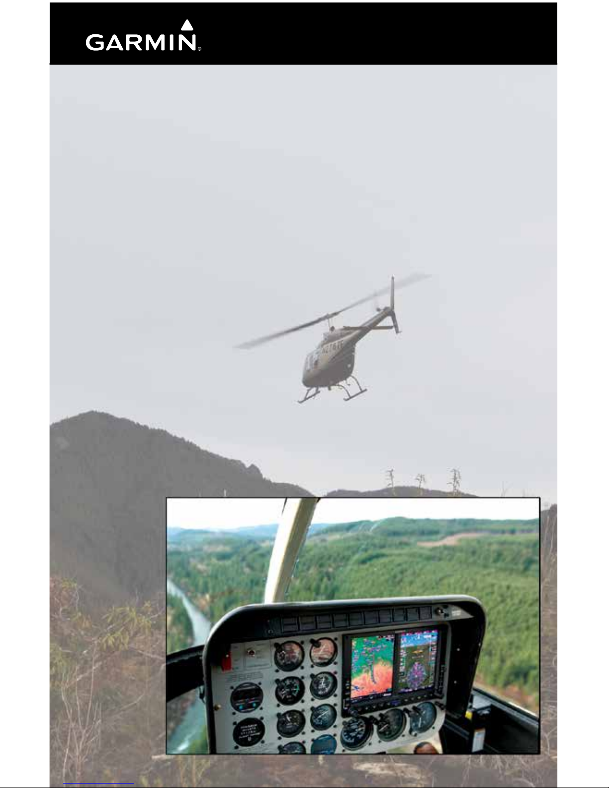
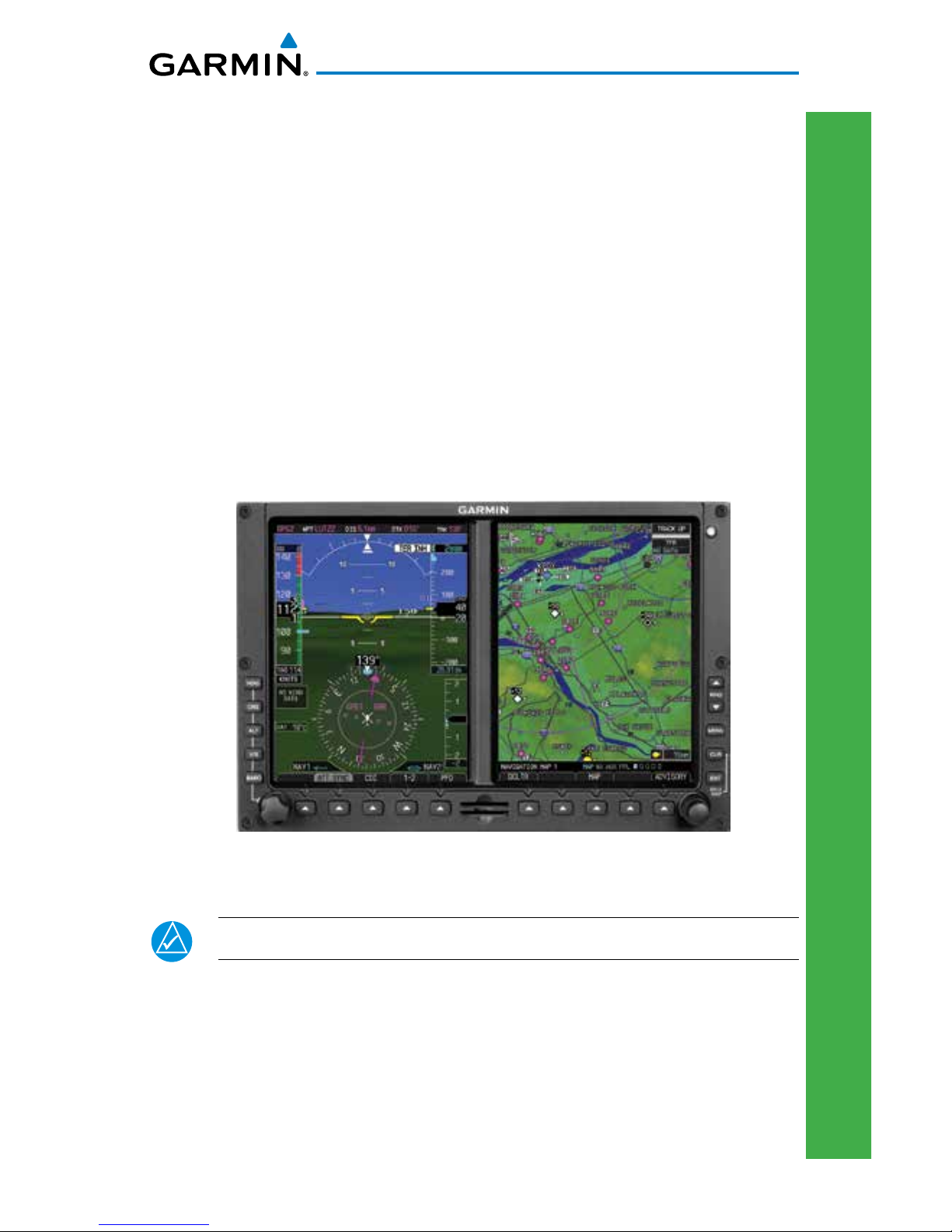
Introduction
This reference guide covers the operation of the GDU 620 as integrated in
the G500H Avionics Display System. The G500H Avionics Display System is
an avionics suite that combines primary flight instrumentation, navigational
information, and a moving map all displayed on dual 6.5 inch color screens. The
G500H system is composed of sub-units or Line Replaceable Units (LRUs). LRUs
have a modular design. This design greatly eases troubleshooting and maintenance
of the G500H system. A failure or problem can be isolated to a particular LRU,
which can be replaced quickly and easily. Each LRU has a particular function,
or set of functions, that contributes to the system’s operation. For more details
on the G500H system, refer to the latest revision of the G500H Pilot’s Guide,
P/N 190-01150-02.
PFD/MFD
NOTE: Some G500Hs have the right-side display configured as the PFD.
2 G500H Cockpit Reference Guide
190-01150-03 Rev F
PRIMARY FLIGHT DISPLAY (PFD)
PRIMARY FLIGHT DISPLAY
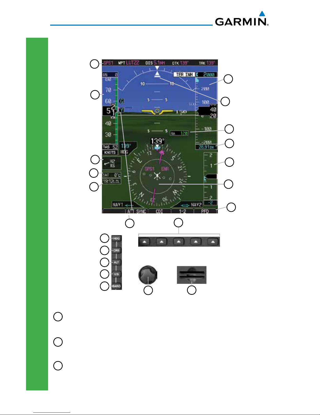
Primary Flight Display (PFD)
6
7
8
9
10
11
12
13
3
2
1
18
19
17
16
15
14
5
4
20
21
Primary Flight Display (PFD)
1
NAV Status Bar: Displays which GPS is selected as the Active Source, Active Waypoint
(WPT), Distance to Waypoint (DIS), Desired Track (DTK) and Current Track (TRK).
2
Airspeed Tape: Displays Groundspeed (GS), Overspeed Range, Maximum (Vne) Speed
with Engine On, Airspeed Trend, Current Airspeed, Max (Vne) Speed with Engine Off
OR Max Autorotation Speed, and True Airspeed (TAS). Markings dependent upon
configuration at time of installation. Reference AFM or POH.
3
Wind Vector: Displays direction and speed of wind.

3
G500H Cockpit Reference Guide
190-01150-03 Rev F
PRIMARY FLIGHT DISPLAY (PFD)
PRIMARY FLIGHT DISPLAY
4
Outside Air Temperature (SAT, TAT, or ISA): Displays the current outside air
temperature.
5
Attitude Sync Soft Key: Allows the synchronization of the aircraft to the horizon in
level flight.
6
Heading Select Key: Press HDG and turn PFD knob to set heading bug.
7
Course Select Key: Press CRS and turn PFD knob to set the course of the selected
source (VOR1, VOR2, GPS1, or GPS2).
8
Altitude Select Key: Press ALT and turn PFD knob to set altimeter bug.
9
V/S (Vertical Speed) Select Key: Press V/S and turn PFD knob to set V/S bug.
10
Barometer Select Key: Press BARO and turn PFD knob to change barometric setting.
11
PFD Knob: Turn PFD knob to change bug settings, Heading Bug, Course, Altitude Bug,
V/S Bug, and Barometer setting.
12
Soft Keys: Used to select available options on PFD or MFD.
13
SD Card Slots, Upper and Lower: The lower slot is used for the supplemental database
card, including aviation database updates. The upper slot may be used to update the
internal aviation database.
14
Soft Key Labels: Located on the bottom screen of the PFD and MFD. Selection is done
by pressing the corresponding soft key. Soft keys that are available have the labels
shown as white text on a black background. Soft keys that are selected have the labels
shown as black text on a gray background. Soft keys that are unavailable have the
labels shown as gray text on a black background.
15
Horizontal Situation Indicator (HSI): Displays the Selected Heading Box, Current
Heading, Turn Rate Markings, and Heading Trend.
16
Vertical Speed Tape: Displays Vertical Speed and the Vertical Speed Bug
17
Barometric (BARO) Setting: Displays the current setting of barometric pressure.
18
Roll Pointer and Slip/Skid Indicator: The slip/skid indicator is the bar beneath the roll
pointer. The indicator moves with the roll pointer and laterally away from the pointer
to indicate lateral acceleration (slip/skid).
19
Altitude Tape: Displays Current Altitude, Altitude Trend, Altitude Bug, Altitude
Minimums Bug and BARO setting.
20
Radar Altimeter Display: Displays current height above ground from the radar
altimeter. Brown band in altitude tape represents the ground.
21
Clock or Timer window.

4 G500H Cockpit Reference Guide
190-01150-03 Rev F
PRIMARY FLIGHT DISPLAY (PFD)
PRIMARY FLIGHT DISPLAY
Airspeed Tape
The upper left portion of the PFD display provides Groundspeed, Airspeed
Trend, Current Airspeed, and True Airspeed information. Current Airspeed is
normally shown in white on the black pointer. The Trend Indicator (magenta
line) indicates what the airspeed will be in six seconds, if the current acceleration
is maintained. If the current acceleration will cause the airspeed to exceed Vne in
six seconds, the airspeed is displayed in yellow. If the current airspeed exceeds
Vne, the pointer changes to red with white text.
NOTE: Airspeed tape markings are dependent upon configuration at
the time of installation. Reference the POH for more details.
Maximum (Vne) Speed
with Engine On
Maximum (Vne Power Off) Speed with
Engine Off or Maximum Autorotation
Speed.
One of the two markings types is selected
during the installation configuration.
Vne
Groundspeed
True Airspeed
Current
Airspeed
Airspeed Tape
Overspeed
Overspeed Indication
Airspeed Tape Markings
Trend Indicator
OR
5
G500H Cockpit Reference Guide
190-01150-03 Rev F
PRIMARY FLIGHT DISPLAY (PFD)
PRIMARY FLIGHT DISPLAY
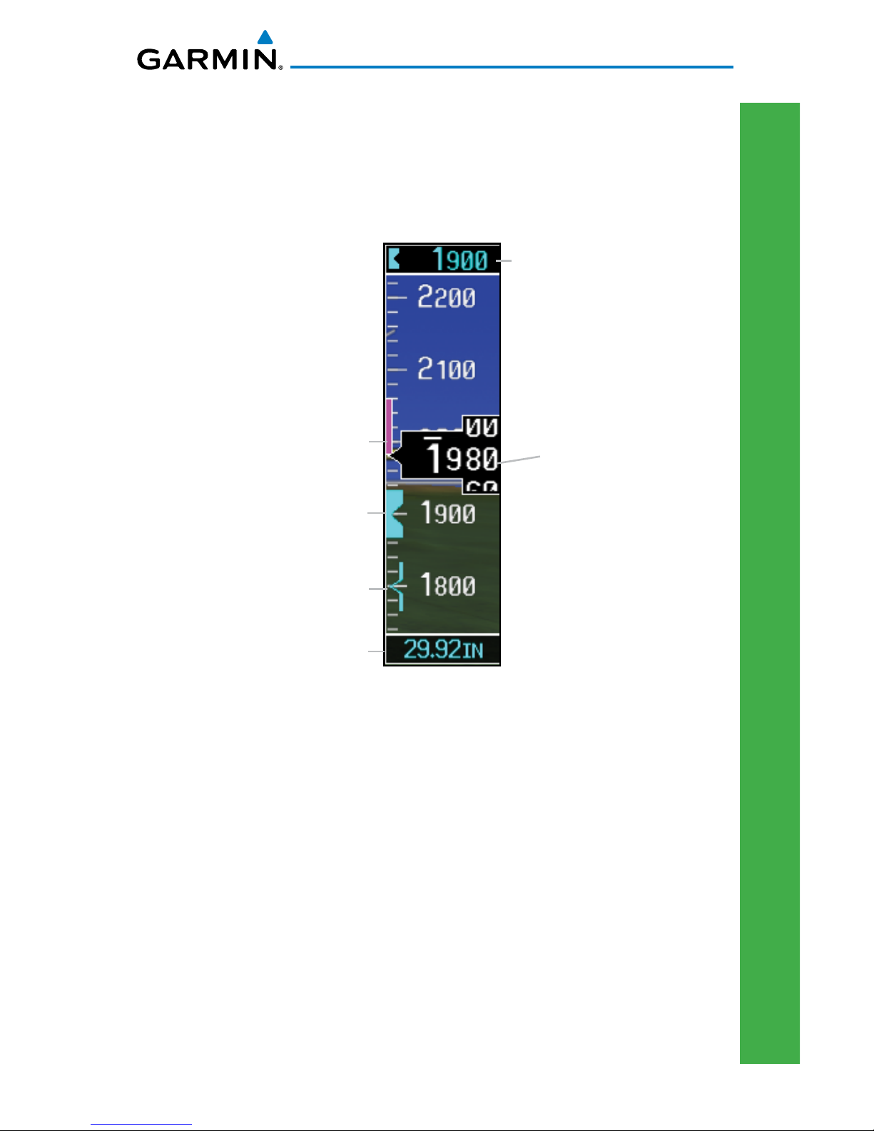
Altitude Tape
The upper right portion of the PFD displays the Altitude Bug setting, Current
Altitude, Altitude Trend, Altitude Minimums Bug, and the current BARO Setting.
The Altitude Trend indicates what the altitude will be in six seconds if the current
vertical speed is maintained.
Altitude Bug Setting
Altitude Trend
BARO Setting
Current Altitude
Altitude Tape
Altitude Bug
Altitude Minimums Bug
Barometric Pressure
The Barometric Pressure Setting (BARO setting) is displayed at the bottom of
the altitude tape. To change the BARO setting, press the BARO key and turn the
PFD knob to the desired pressure. To select standard pressure (29.92in), press
the PFD knob.
6 G500H Cockpit Reference Guide
190-01150-03 Rev F
PRIMARY FLIGHT DISPLAY (PFD)
PRIMARY FLIGHT DISPLAY
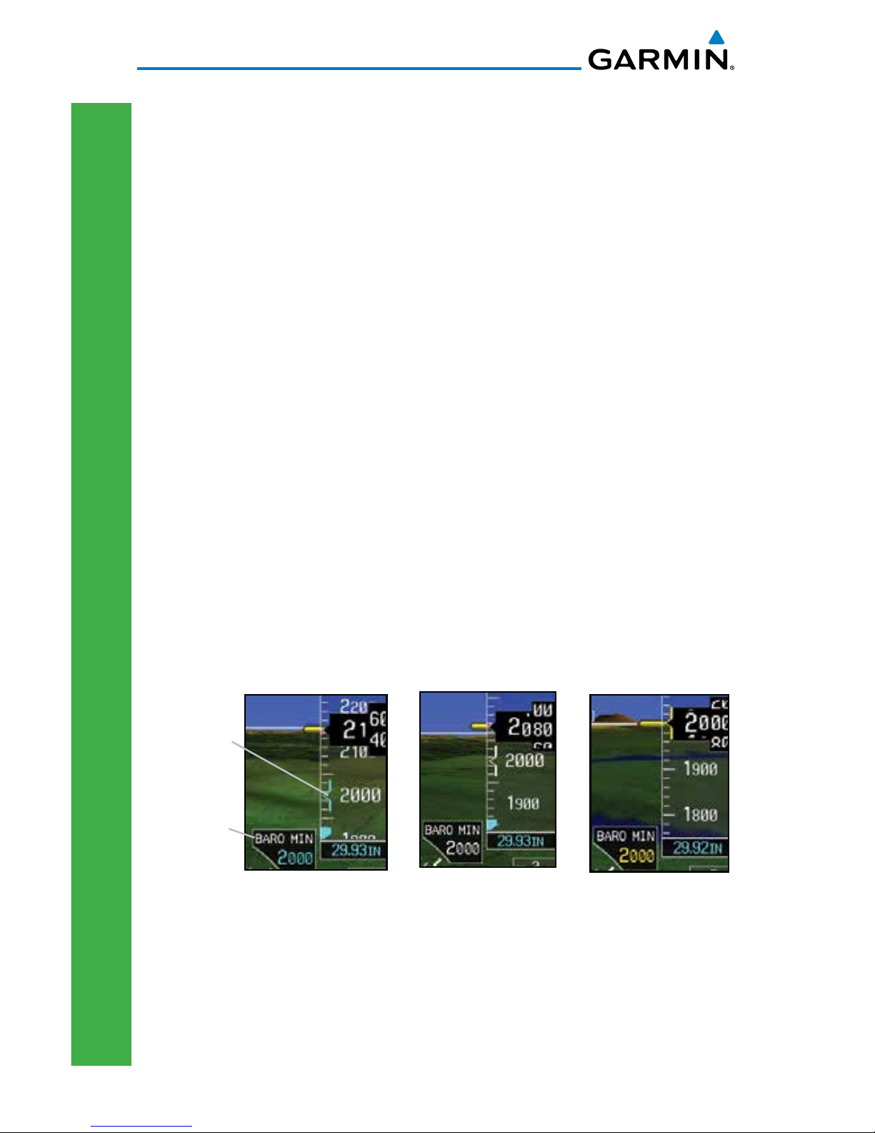
Minimums Bug (Barometric or Radar Altimeter)
For altitude awareness, an Altitude Minimums Bug commonly referred to as
the Minimums Bug, can be set. the source of data for minimums alerting can be
selected to either barometric altitude or radar altitude (if installed.) When active
and within 2500 feet of the selected minimums altitude, the minimums bug
setting is displayed to the bottom left of the altimeter. When set, a bug appears
parked at the bottom of the altitude tape and moves up the tape as the set altitude
comes into view.
• When the aircraft altitude descends to within 2500 feet of the selected
altitude minimums setting, the minimums box appears with the altitude
value in cyan text. Once in range, the Minimums Bug appears in cyan
on the altitude tape.
A portion of the Minimums Bug will be displayed at
the bottom of the altitude tape if the selected altitude minimums bug is off
of the tape.
• When the aircraft is within 100 feet of the selected altitude minimums
setting, the bug and the altitude text turn white.
• Once the aircraft reaches the selected altitude minimums setting, the
bug and the altitude text turn yellow and the aural alert, “Minimums,
minimums” is heard one time.
Minimums Annunciations using BARO for Source
Minimums
Box
Minimums
Bug
Bug and text are
cyan within 2500 ft
Bug and text are
white within 100 ft
Bug and text
are yellow when
altitude reached
Alerting is inhibited while the aircraft is on the ground and also, if a value has
been set for altitude alerting, until the aircraft reaches 150 feet above the setting
for the alert.
7
G500H Cockpit Reference Guide
190-01150-03 Rev F
PRIMARY FLIGHT DISPLAY (PFD)
PRIMARY FLIGHT DISPLAY
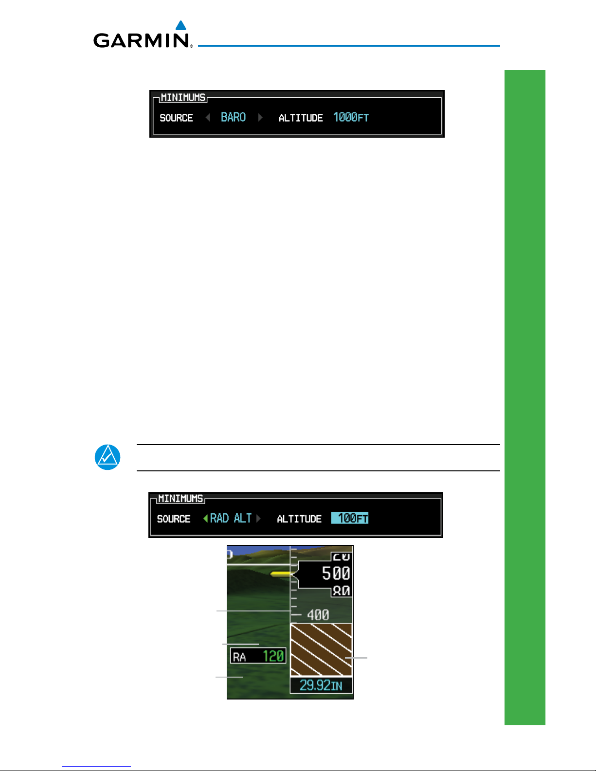
To set the altitude for the Minimums Bug:
1) While viewing the Active Flight Plan page of the FPL Group, press the small
MFD knob to activate the cursor and turn the large MFD knob to the Source
selection.
2) Turn the small MFD knob to select Off, BARO, or RAD ALT.
3) Turn the large MFD knob to the ALTITUDE portion of the MINIMUMS section.
4) Turn the small MFD knob to enter the desired altitude. Press the ENT key to
confirm selection.
5) When finished, press the small MFD knob to exit the MINIMUMS box.
The Minimums Bug can also be set from the Charts page of the FPL.
1) While viewing the Charts page of the FPL Group, press the MENU key and
select “Set Minimums” from the Options menu.
2) Turn the small MFD knob to select Off, BARO, or RAD ALT.
3) Press the ENT key to move to enter altitude. Turn the small MFD knob to
enter the desired altitude. Press the ENT key to confirm selection.
NOTE: BARO will not be available for selection on G500H models.
Brown band represents the ground.
Minimums Box
Radar Altimeter Value
Radar Altimeter
Minimums Bug
Minimums Annunciations using RAD ALT for Source
8 G500H Cockpit Reference Guide
190-01150-03 Rev F
PRIMARY FLIGHT DISPLAY (PFD)
PRIMARY FLIGHT DISPLAY
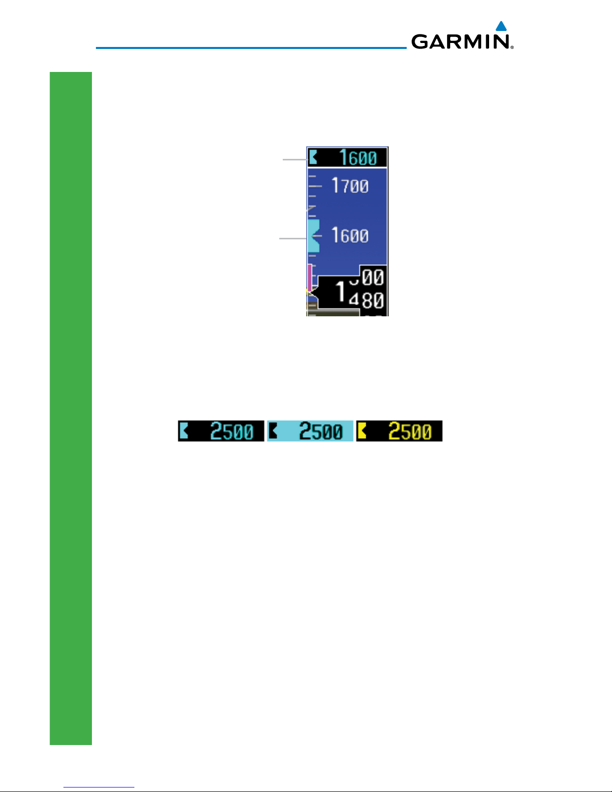
Altitude Bug
The Altitude Bug is displayed on the Altitude Tape at the selected altitude bug
setting. A portion of the Altitude Bug will be displayed at the top or bottom of
the altitude tape if the selected altitude bug is off of the tape.
Altitude Bug
Altitude Bug
Altitude Bug
Setting
The Altitude Bug provides visual and aural altitude alerting. Aural alerting
occurs within 200 feet (or 1000 feet, as configured) of the Altitude Bug setting
or when deviating beyond 200 feet of the bug.
Within 1000 ft
Within 200 ft
Deviation of
+/- 200ft
Altitude Bug Indications
9
G500H Cockpit Reference Guide
190-01150-03 Rev F
PRIMARY FLIGHT DISPLAY (PFD)
PRIMARY FLIGHT DISPLAY
Wind Vectors
The PFD will display a Wind Vector Field to the left of the HSI when configured
by the user. There are four different styles of wind vector displays available. Refer
to the System Setup page in the AUX Group section of this guide for instructions
on selecting wind vector style. Wind Vectors can only be calculated when the
aircraft is in the air. When airspeed is less than 20 knots, the Wind Vector windows
will indicate, “No Wind Data”.
Wind Vector Field
Wind Vector Display
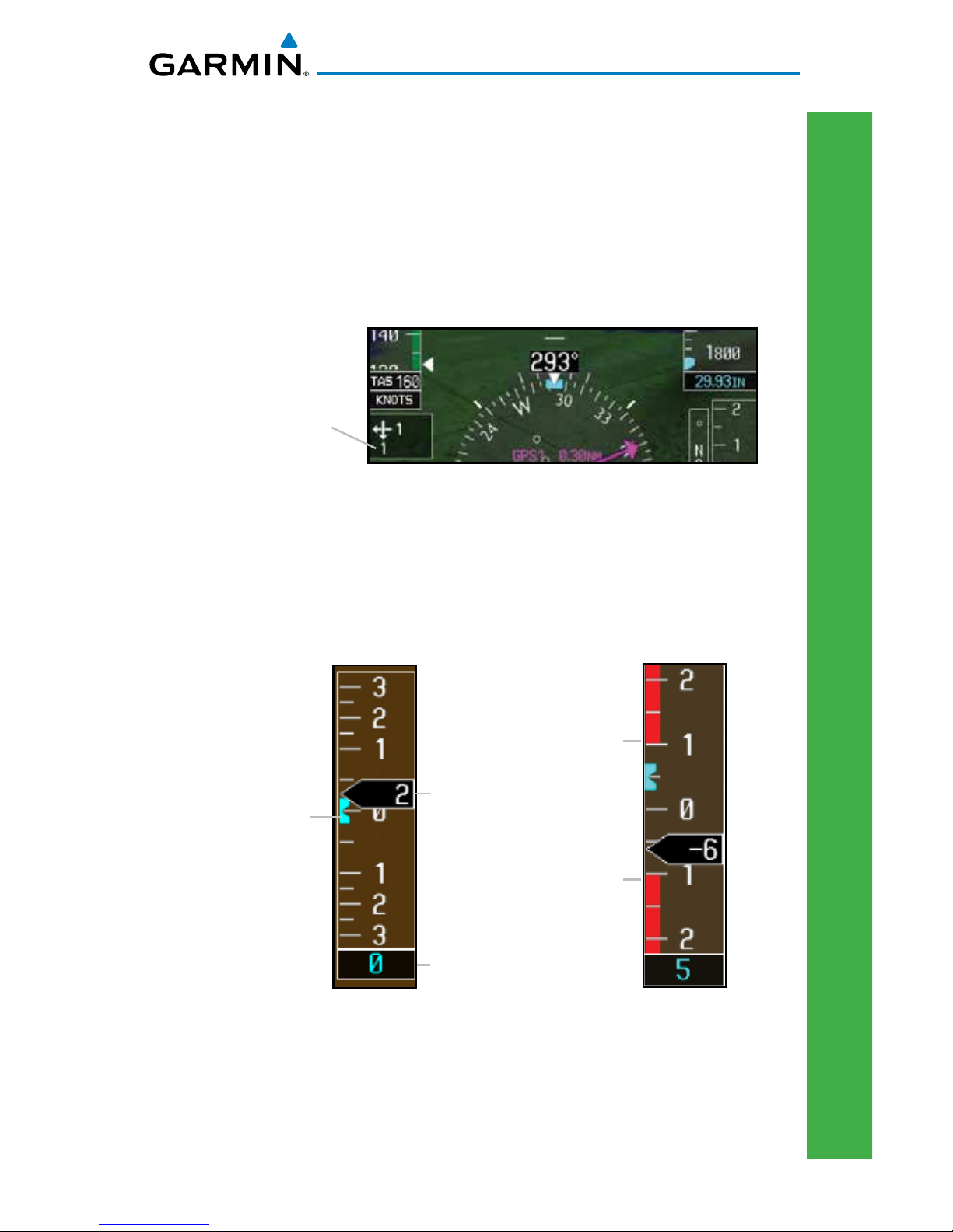
Vertical Speed (V/S)
The Vertical Speed Tape and Vertical Speed Bug are displayed below the Altitude
Tape. For rotorcraft with vertical speed operating limitations, red bands showing
Vertical Speed Maximum and Minimum ranges will be shown on the left side of
the Vertical Speed tape.
Current Vertical Speed
Vertical Speed Minimum
Vertical Speed Maximum
Vertical Speed Bug Setting
Vertical Speed
Vertical Speed Bug
Vertical Speed - Rotorcraft

10 G500H Cockpit Reference Guide
190-01150-03 Rev F
PRIMARY FLIGHT DISPLAY (PFD)
PRIMARY FLIGHT DISPLAY
Vertical Deviation Indicator (VDI)
The Vertical Deviation Indicator is displayed for GPS and ILS approaches
with vertical guidance. The GPS approach glidepath is shown in magenta
(G and indicator), while the ILS approach glideslope is shown in green
(G and indicator.)
GPS Approach
Vertical Deviation Source
Vertical Deviation Indicator
ILS Approach
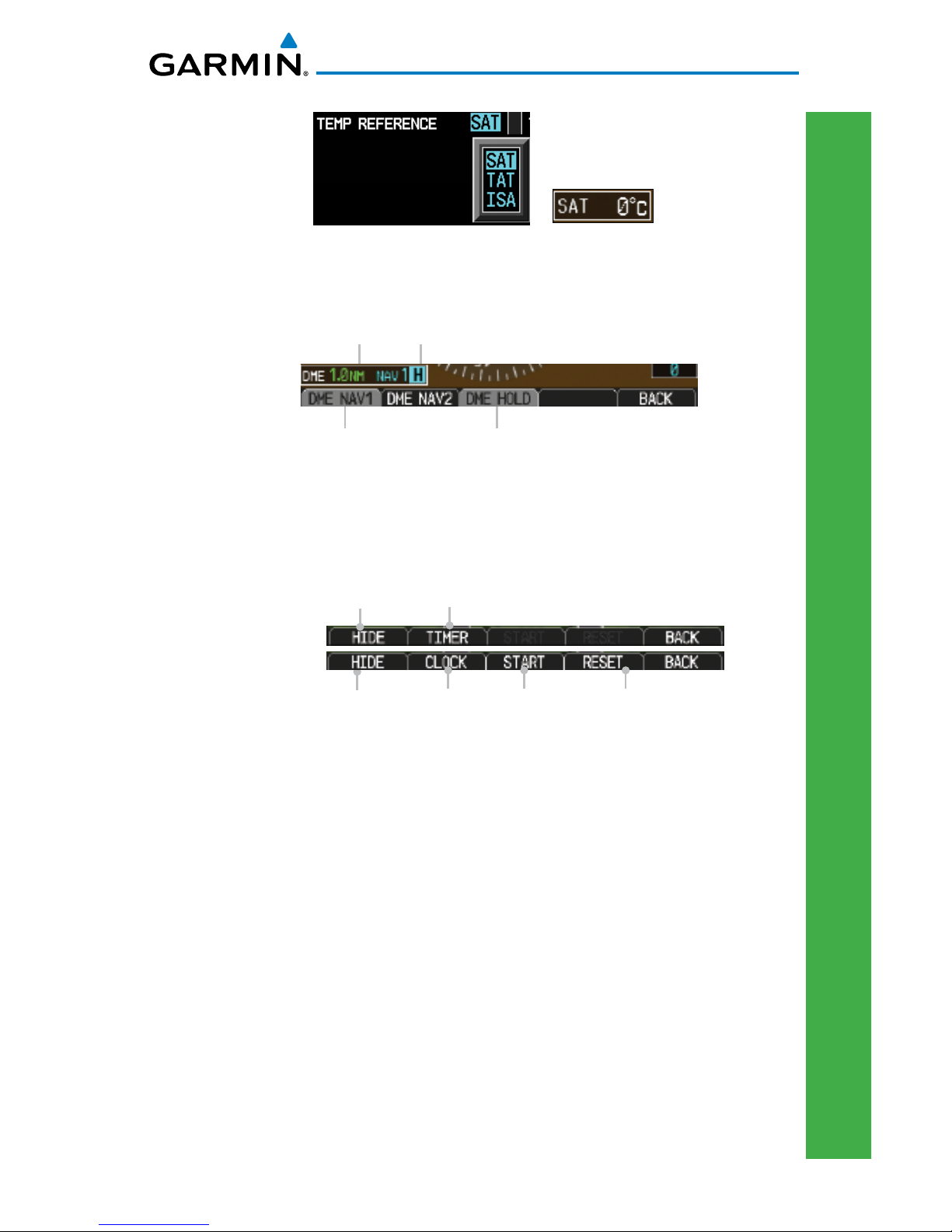
Temperature Display
The outside air temperature is displayed to the left of the HSI. The air data
computer calculates the temperature based on temperature probe and pitot/
static inputs. The units (°C or °F) and temperature reference are selected on the
AUX – SYSTEM SETUP page. The temperature reference can be selected to one
of the following choices:
•
Static Air Temperature (SAT) – This is the calculated temperature of the
stationary (static) outside air. Conceptually, this is the temperature that
would be read on a thermometer floating stationary at the current location.
• Total Air Temperature (TAT) – This is the calculated temperature of the
outside air as it moves past the aircraft, including the rise in temperature
due to air compression and friction at the current airspeed.
• Difference from International Standard Atmosphere (ISA) – This is the
difference between SAT and standard (ISA) temperature at the current
altitude. This provides an indication of how much warmer/colder the
temperature is from a “standard” atmosphere.
11
G500H Cockpit Reference Guide
190-01150-03 Rev F
PRIMARY FLIGHT DISPLAY (PFD)
PRIMARY FLIGHT DISPLAY
DME Indication
DME information is displayed in a window in the lower left corner of the PFD.
The distance to the station and the NAV source used are shown.
Selected DME
DME Information
Set Hold for Selected DME
DME Hold Annunciation
DME Indication
Clock/Timer
The Clock/Timer function displays a clock or timer window in the lower left
corner of the PFD.
Show/Hide Timer
Show/Hide Clock
Select Clock
Select Timer
Start/StopTimer Reset Timer
Clock and Timer Functions
12 G500H Cockpit Reference Guide
190-01150-03 Rev F
PRIMARY FLIGHT DISPLAY (PFD)
PRIMARY FLIGHT DISPLAY
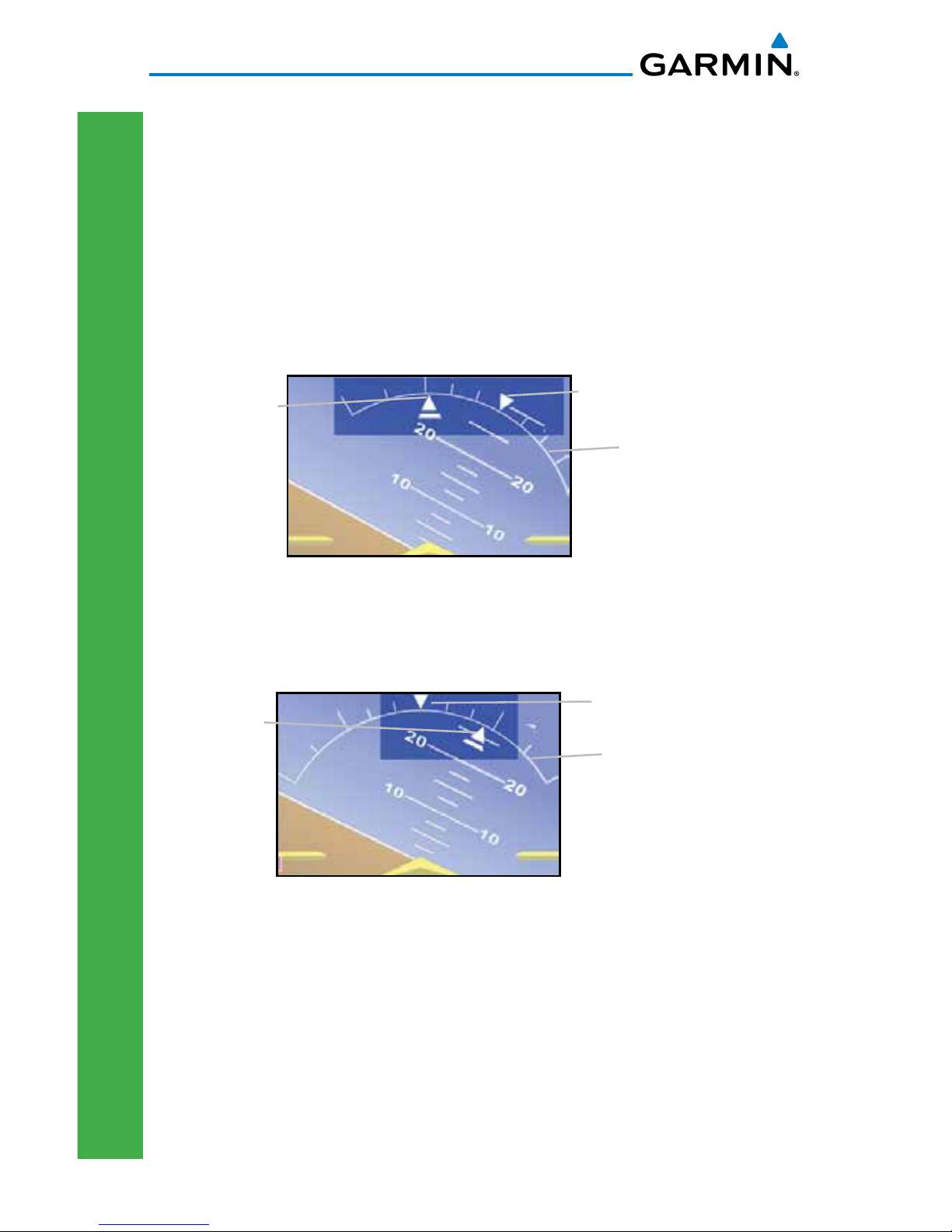
Attitude Indicator
The standby mechanical Attitude Indicator in your aircraft is either a Ground
Pointer or a Roll Pointer configuration. The GDU 620 Attitude Indicator has been
configured in either a Ground Pointer or a Roll Pointer configuration to match
the configuration of your aircraft’s standby Attitude Indicator.
In an aircraft with an Attitude Indicator that has a Ground Pointer, the pointer
above the roll scale shifts with the roll or bank angle of the aircraft to keep the
Roll Scale Zero Pointer pointing towards the ground.
Roll Pointer
Roll Scale Zero Pointer
Roll Scale
Attitude Indicator with a Ground Pointer Configuration in a Left Turn
In an aircraft with an Attitude Indicator that has a Sky Pointer, the pointer
below the roll scale shifts with the roll or bank angle of the aircraft to keep the
Roll Pointer pointing towards the sky.
Roll Scale
Roll Scale Zero Pointer
Roll Pointer
Attitude Indicator with a Sky Pointer Configuration in a Left Turn
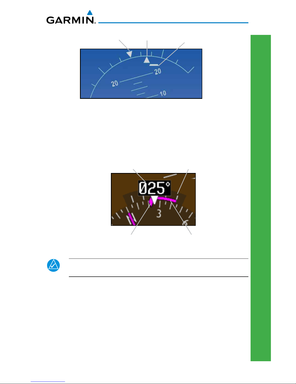
The Slip/Skid Indicator is the bar beneath the roll pointer. The indicator moves
with the roll pointer and moves laterally away from the pointer to indicate lateral
acceleration. Slip/skid is indicated by the location of the bar relative to the pointer.
One bar displacement from the roll pointer is equivalent to one ball displacement
on a traditional Slip/Skid Indicator.
13
G500H Cockpit Reference Guide
190-01150-03 Rev F
PRIMARY FLIGHT DISPLAY (PFD)
PRIMARY FLIGHT DISPLAY
Slip/Skid Indicator
Roll Pointer Slip/Skid Indicator
Roll Scale Zero
Horizontal Situation Indicator (HSI): Aircraft Heading
The top of the HSI displays current heading, current GPS track (magenta
diamond), heading trend, and turn rate markings. The heading trend indicates
the rate of turn. Marking for rate of turn are provided at half-standard (1.5°/sec)
and standard (3°/sec) rate.
Current Heading Turn Rate Markings
Heading TrendCurrent GPS Track
HSI Heading Markings
NOTE: If magnetic heading is lost, GPS ground track will be displayed
in place of heading.
14 G500H Cockpit Reference Guide
190-01150-03 Rev F
PRIMARY FLIGHT DISPLAY (PFD)
PRIMARY FLIGHT DISPLAY
Adjusting the Course Pointer
Press the CRS key and turn the PFD knob to select a course for a VOR/ILS or
OBS mode course.
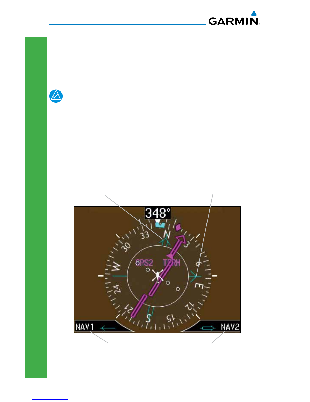
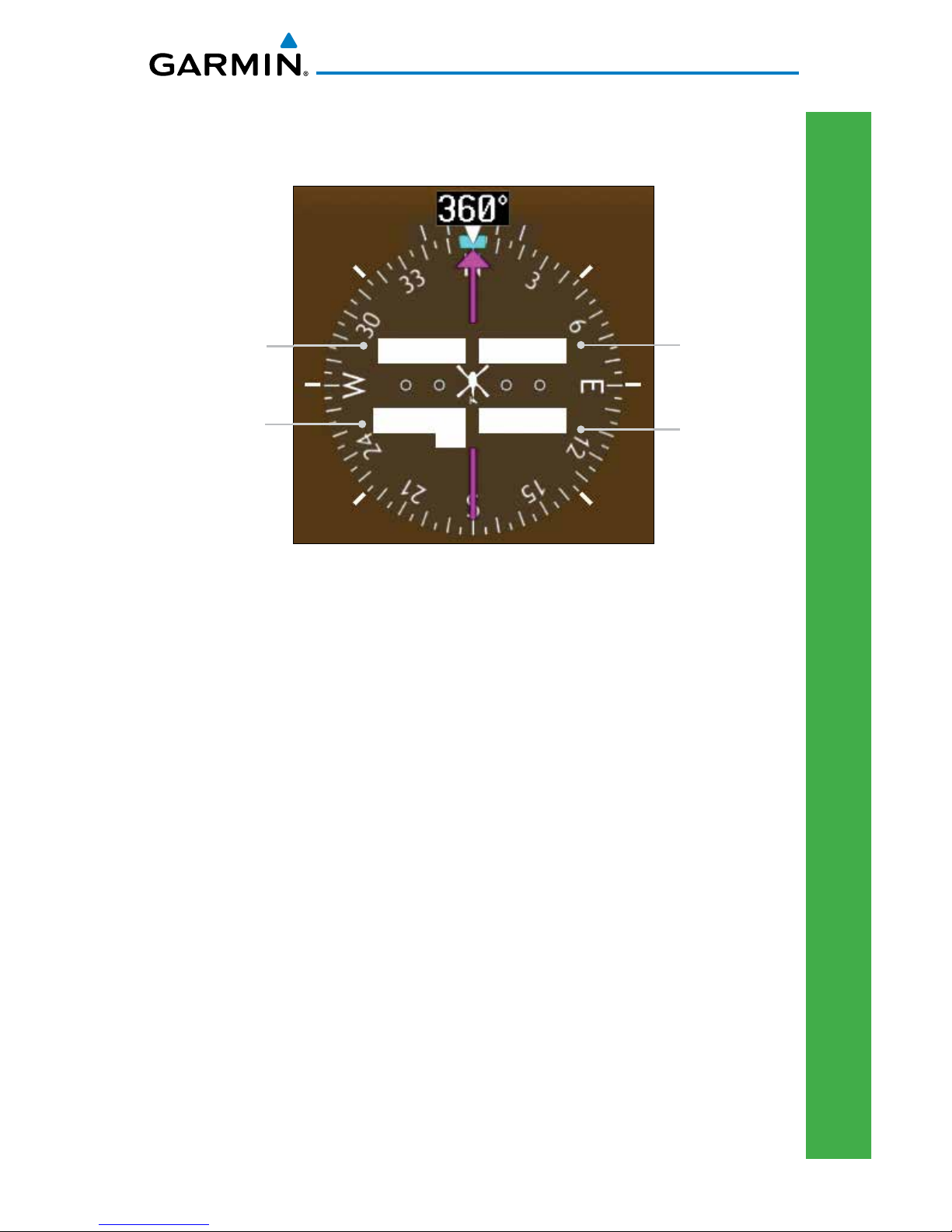
HSI Bearing Pointers
NOTE: The Bearing Pointer for navigation source 1 (BRG1) will be an
arrow with a single line. The Bearing Pointer for navigation source 2
(BRG2) will be an arrow with a double line.
To toggle between the available bearing pointers, press the PFD soft key followed
by the BRG1 or BRG2 soft keys.
The BRG1 soft key cycles through modes NAV1 and GPS1. Additionally, ADF
is available if an ADF source is installed.
The BRG2 soft key cycles through modes, NAV2 and GPS2 if a second NAV
or GPS source is available. Additionally, ADF is available if an ADF source is
installed.
Selected source for
BRG 1 bearing pointer
NAV2 Bearing Pointer
NAV1 Bearing Pointer
Selected source for
BRG 2 bearing pointer
Bearing Pointers on the HSI
15
G500H Cockpit Reference Guide
190-01150-03 Rev F
PRIMARY FLIGHT DISPLAY (PFD)
PRIMARY FLIGHT DISPLAY
CDI Source
GPS Mode
GPS Advisory
LOI
Suspend
MSG
LOI
OBS
SUSP
GPS1
GPS2
VOR1
VOR2
LOC1
LOC2
OCN
ENR
TERM
APR
LNAV
LNAV+
LPV
LNAV/VNAV
LP
LP +V
1.00nm
0.30nm
PFD HSI Annunciations
CDI Source
The CDI Source on the HSI will display which navigation source is selected.
Navigation sources available: GPS1, VOR1, or LOC1.
Navigation sources available: GPS2, VOR2, or LOC2, if a second source is available.
GPS Mode
The GPS Mode annunciation on the HSI indicates the current CDI scaling of the
GPS navigator. See the GPS navigator pilot’s guide for a description of each mode.
GPS Advisory
MSG: Displays when a new advisory message is displayed on the GPS navigator.
LOI (Loss of Integrity): Displays when GPS integrity is lost.
Suspend
OBS: Displays when OBS mode is activated.
SUSP: Displays when automatic waypoint sequencing on the interfaced GPS unit is
suspended.
16 G500H Cockpit Reference Guide
190-01150-03 Rev F
PRIMARY FLIGHT DISPLAY (PFD)
PRIMARY FLIGHT DISPLAY
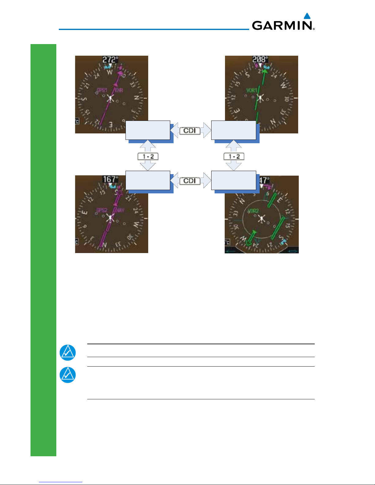
Switching Between Navigation Sources
GPS
NAVIGATOR 2
VLOC
NAVIGATOR 2
GPS
NAVIGATOR 1
VLOC
NAVIGATOR 1
CDI Sources
The Course Deviation Indicator (CDI) can display two sources of navigation:
GPS or NAV (VOR or LOC). Press the CDI soft key to toggle between the available
CDI modes, (GPS or VOR).
If a second GPS source or NAV source is available, pressing the 1 - 2 soft key
will toggle the navigation sources (VOR1 and VOR2, or GPS1 and GPS2).
NOTE: Verify the navigation source by the indication on the HSI.
NOTE: The selected navigator is the source for all PFD and MFD
functions, except for bearing pointers and external TAWS PFD
annunciations.
17
G500H Cockpit Reference Guide
190-01150-03 Rev F
PRIMARY FLIGHT DISPLAY (PFD)
PRIMARY FLIGHT DISPLAY
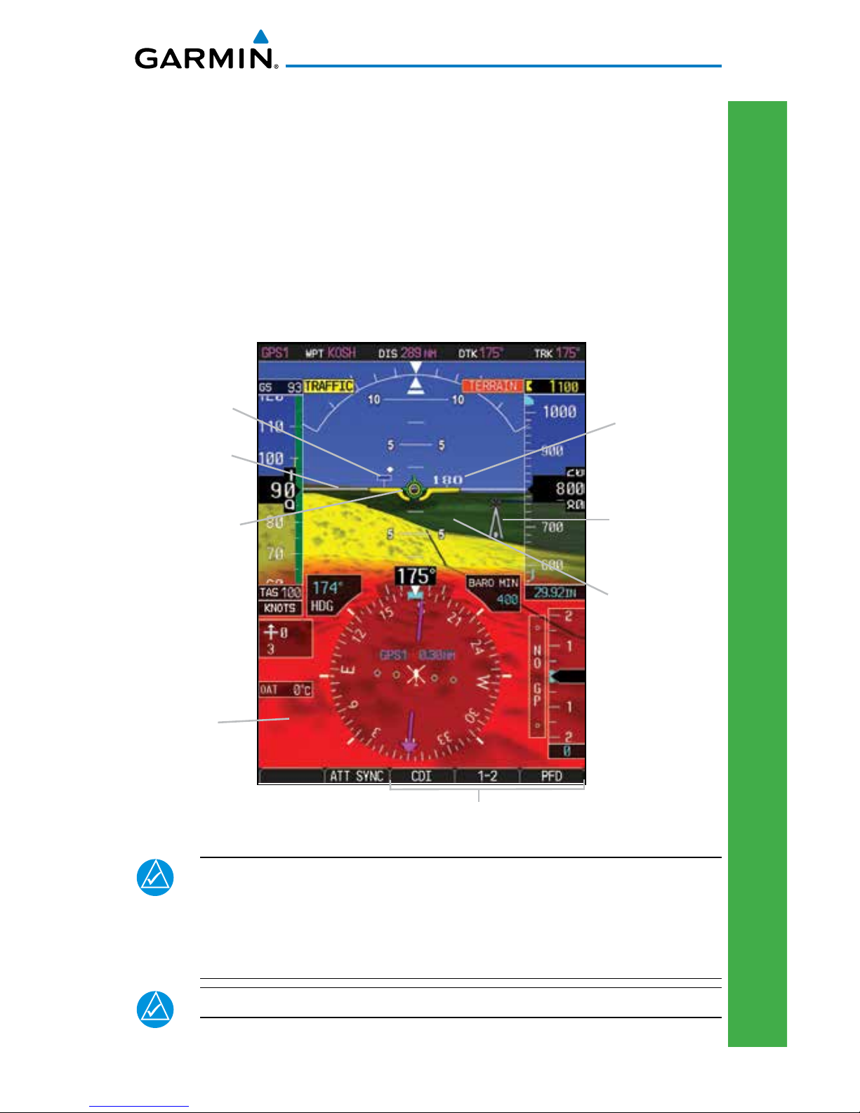
Additional Features
Garmin Terrain-HSVT™ (Optional)
Garmin Terrain-HSVT is offered as an optional feature to the G500H.
HSVT is primarily comprised of a computer-generated forward-looking, attitude
aligned view of the topography immediately in front of the aircraft from the pilot’s
perspective. HSVT information is shown on the PFD.
HSVT offers a three-dimensional view of terrain and obstacles. Terrain and
obstacles that pose a threat to the aircraft in flight are shaded yellow or red.
Obstacle
Zero-Pitch
Line
SVT Soft Keys
Horizon
Heading
Mark
HSVT
Terrain
Flight
Path
Marker
Airport
Sign
Terrain
Threat
Terrain-HSVT Imagery
NOTE: Terrain-HSVT will become disabled if the databases necessary
to display Terrain-HSVT are unavailable (generating a GDU DB ERR or
HSVT DISABLED alert) or AHRS or GPS data is unavailable.
Terrain-HSVT may be restored once the fail conditions are removed by
following the steps in “Displaying HSVT Terrain.”
NOTE: Airport Signs will only display airports, not heliports.

18 G500H Cockpit Reference Guide
190-01150-03 Rev F
PRIMARY FLIGHT DISPLAY (PFD)
PRIMARY FLIGHT DISPLAY
The following features are part of the Terrain-HSVT system. For more details
refer to the latest revision of the G500H Pilot’s Guide, 190-01150-02.
• Flight Path Marker • Airport Signs
• Horizon Heading Marks • Runway Display
• Terrain/Obstacle Display and Alerting • Water
• Three-dimensional Traffic
• Zero-Pitch Line
NOTE: Terrain-HSVT may be deactivated under certain conditions, such
as loss of heading. Once condition is resolved, reactivate Terrain-HSVT,
press the PFD soft key followed by the SYN VIS soft key, then the SYN
TERR soft key.
NOTE: Terrain-HSVT features are not a substitute for standard course
and altitude deviation information using the CDI, VSI, and VDI.
Displaying Garmin Terrain-HSVT™ Terrain
1) Press the PFD soft key.
2) Press the SYN VIS soft key.
3) Press the SYN TERR soft key.
4) Press the BACK soft key to return to the previous page.
Displaying Heading on the Horizon
1) Press the PFD soft key.
2) Press the SYN VIS soft key.
3) If not already enabled, press the SYN TERR soft key.
4) Press the HRZN HDG soft key.
5) Press the BACK soft key to return to the previous page.
Displaying Airport Signs
NOTE: The “Airport Signs” feature will only display airports, not
heliports.
1) Press the PFD soft key.
2) Press the SYN VIS soft key.
3) If not already enabled, press the SYN TERR soft key.
4) Press the APTSIGNS soft key.
5) Press the BACK soft key to return to the previous page.
 Loading...