

Garmin GDL 69/69A, GDL 69, GDL 69A Installation Manual
GDL 69/69A
Installation Manual
190-00355-02 June 2006 Revision E

This Page Intentionally Left Blank
© 2004-2006
Garmin Ltd. or its subsidiaries
All Rights Reserved
Except as expressly provided herein, no part of this manual may be reproduced, copied, transmitted,
disseminated, downloaded or stored in any storage medium, for any purpose without the express prior
written consent of Garmin. Garmin hereby grants permission to download a single copy of this manual
and of any revision to this manual onto a hard drive or other electronic storage medium to be viewed and
to print one copy of this manual or of any revision hereto, provided that such electronic or printed copy of
this manual or revision must contain the complete text of this copyright notice and provided further that
any unauthorized commercial distribution of this manual or any revision hereto is strictly prohibited.
Garmin International, Inc.
1200 E. 151
st
Street
Olathe, KS 66062 USA
Telephone: 913.397.8200
Aviation Panel-Mount Technical Support Line (Toll Free) 1.888.606.5482
www.garmin.com
Garmin (Europe) Ltd.
Unit 5, The Quadrangle
Abbey Park Industrial Estate
Romsey, SO51 9DL U.K.
44/1794.519944
44/1794.519222
Garmin AT, Inc.
2345 Turner Rd., SE
Salem, OR 97302 USA
Telephone: 503.581.8101
RECORD OF REVISIONS
Revision Revision Date Description ECO #
1 12/3/04 Experimental Release -----A 12/8/04 Production Release 28645
B 2/3/05 Add 400/500 interface 29512
C 7/27/05 Add GDU 104x interface and SW version 3.00 32449
D 9/15/05 Corrected specification sheet 33407
E 6/30/06 Remove XM antenna installation data and added GA 55A
and GA 57 antenna references.
38688
GDL 69/69A Installation Manual Page iii
190-00355-02 Revision E

This manual is written for software version 2.11, 2.13, 2.14, 3.00, 3.01, 3.02 or later. The software
version and information in this document are subject to change without notice. Visit the Garmin web site
(www.garmin.com
and other Garmin products.
) for current updates and supplemental information concerning the operation of this
INFORMATION SUBJECT TO EXPORT CONTROL LAWS
This document may contain information which is subject to the Export Administration Regulations
("EAR") issued by the United States Department of Commerce (15 CFR, Chapter VII, Subchapter C) and
which may not be exported, released, or disclosed to foreign nationals inside or outside of the United
States without first obtaining an export license. A violation of the EAR may be subject to a penalty of up
to 10 years imprisonment and a fine of up to $1,000,000 under Section 2410 of the Export Administration
Act of 1979. Include this notice with any reproduced portion of this document.
WARNING
This product, its packaging, and its components contain chemicals known to the State of California to
cause cancer, birth defects, or reproductive harm. This Notice is being provided in accordance with
California's Proposition 65. If you have any questions or would like additional information, please refer
to our web site at www.garmin.com/prop65
.
Page iv GDL 69/69A Installation Manual
Revision E 190-00355-02

TABLE OF CONTENTS
SECTION PAGE
1
GENERAL DESCRIPTION...................................................................................................................1-1
1.1 Scope.........................................................................................................................................1-1
1.2 Introduction...............................................................................................................................1-1
1.3 Equipment Description .............................................................................................................1-1
1.4 Interfaced Equipment................................................................................................................1-2
1.5 Audio Entertainment Installation Limitations...........................................................................1-2
1.6 XM Satellite Radio ...................................................................................................................1-3
1.7 Interface Summary....................................................................................................................1-3
1.8 Technical Specifications ...........................................................................................................1-4
1.9 Reference Documents...............................................................................................................1-7
1.10 Certification ..............................................................................................................................1-7
1.11 Unpacking Unit.........................................................................................................................1-7
1.12 Warranty Statement ..................................................................................................................1-7
2 INSTALLATION.................................................................................................................................2-1
2.1 Introduction...............................................................................................................................2-1
2.2 Pre-Installation Information......................................................................................................2-1
2.3 Installation Materials ................................................................................................................2-1
2.4 Equipment Mounting ................................................................................................................2-2
2.5 Cabling and Wiring...................................................................................................................2-5
2.6 XM Antenna ...........................................................................................................................2-12
2.7 Weight and Balance................................................................................................................2-17
2.8 Electrical Load Analysis.........................................................................................................2-17
2.9 Cooling Air .............................................................................................................................2-18
2.10 Installing/Inserting Unit..........................................................................................................2-18
3 SYSTEM INTERCONNECTS ................................................................................................................3-1
3.1 Pin Out List...............................................................................................................................3-1
3.2 Functional Descriptions ............................................................................................................3-3
4 SYSTEM CONFIGURATION/CHECKOUT ............................................................................................4-1
4.1 Post-Installation Power Check..................................................................................................4-1
4.2 Initialization of Configuration Module.....................................................................................4-1
4.3 Configure RS-232 Port .............................................................................................................4-3
4.4 System Operational Checkout...................................................................................................4-3
4.5 Activation with XM Satellite Radio .........................................................................................4-5
5 TROUBLESHOOTING .........................................................................................................................5-1
6 LIMITATIONS ...................................................................................................................................6-1
6.1 Operation ..................................................................................................................................6-1
6.2 Installation ................................................................................................................................6-1
7 PERIODIC MAINTENANCE ................................................................................................................7-1
7.1 Audio Suppression....................................................................................................................7-1
7.2 Equipment Calibration..............................................................................................................7-1
7.3 Cleaning....................................................................................................................................7-1
APPENDIX A - STC DATA..........................................................................................................................A-1
APPENDIX B - ENVIRONMENT QUALIFICATION FORM ..............................................................................B-1
APPENDIX C - CONSTRUCTION AND VALIDATION OF STRUCTURES .........................................................C-1
APPENDIX D – INSTALLATION DRAWINGS ................................................................................................D-1
GDL 69/69A Installation Manual Page v
190-00355-02 Revision E

LIST OF FIGURES
Figure 1-1. GDL 69/69A Unit View ........................................................................................................ 1-1
Figure 1-2. GDL 69/69A Remote Rack Unit Dimensions ....................................................................... 1-5
Figure 1-3. GDL 69/69A Modular Rack Unit Dimensions...................................................................... 1-5
Figure 2-1. Suggested Mounting Locations for Remote Rack................................................................. 2-2
Figure 2-2. GDL 69/69A Remote Mount Rack........................................................................................ 2-3
Figure 2-3. Typical Rocker Switches....................................................................................................... 2-4
Figure 2-4. Modular Rack for the G1000................................................................................................. 2-4
Figure 2-5. Garmin Connector Assembly ................................................................................................ 2-7
Figure 2-6. Backshell Assembly .............................................................................................................. 2-8
Figure 2-7. Spider Installation Drawing................................................................................................. 2-10
Figure 2-8. Antenna Installation Location ............................................................................................. 2-13
Figure 2-9. XM Signal Gain Requirements............................................................................................ 2-14
Figure 2-10. TNC Connector Installation............................................................................................... 2-18
Figure 2-11. GDL 69/69A Installation................................................................................................... 2-19
Figure 3-1. Pin Out................................................................................................................................... 3-1
Figure 4-1. Data Link Configuration Page on the MX20......................................................................... 4-3
Figure 4-2. Data Link Configuration Page on the 400/500 Series ........................................................... 4-4
Figure 4-3. Configuration Upload Page - GDU 104x .............................................................................. 4-4
Figure 4-4. Configuration Page – GDU 104x .......................................................................................... 4-4
Figure D-1. GDL 69 Interconnect to MFD and Audio Panel.................................................................. D-3
Figure D-2. GDL 69 Interconnect to GDU 104x ....................................................................................D-4
Figure D-3. GDL 69 Interconnect to 400/500 Series..............................................................................D-5
Figure D-4. GDL 69 Interconnect to MFD and 400/500 Series.............................................................. D-6
Figure D-5. Interconnect to Warning Horns............................................................................................ D-7
Figure D-6. Optional Audio Attenuation ................................................................................................ D-8
Page vi GDL 69/69A Installation Manual
Revision E 190-00355-02

LIST OF TABLES
Table 1-1. Interfaced Equipment List....................................................................................................... 1-2
Table 1-2. GDL 69/69A Specifications.................................................................................................... 1-4
Table 1-3. GA 55, GA 55A, GA 57 Specifications.................................................................................. 1-4
Table 1-4. GDL 69/69A Unit Dimensions............................................................................................... 1-4
Table 1-5. XM Antennas.......................................................................................................................... 1-6
Table 1-6. XM Satellite Radio Antenna Minimum Requirements........................................................... 1-6
Table 1-7. GA 55, GA 55A, GA 57 XM Antenna Specifications............................................................ 1-6
Table 1-8. Referenced Publications.......................................................................................................... 1-7
Table 2-1. Kit Contents............................................................................................................................ 2-1
Table 2-2. Pin Contact Part Numbers....................................................................................................... 2-5
Table 2-3. Recommended Crimp Tools ................................................................................................... 2-6
Table 2-4. Garmin Connector Assembly.................................................................................................. 2-7
Table 2-5. Spider Kits .............................................................................................................................. 2-9
Table 2-6. Spider Installation Required Parts .......................................................................................... 2-9
Table 2-7. XM Gain/Loss Component Calculation................................................................................ 2-15
Table 2-8. Unit Weights......................................................................................................................... 2-17
Table 3-1. Pin Out List............................................................................................................................. 3-1
Table 5-1. Troubleshooting Guide ........................................................................................................... 5-1
Table C-1. Static Test Load (GDL 69 with Remote Rack) ......................................................................C-1
Table C-2. Static Test Load (GDL 69A with Remote Rack) ...................................................................C-1
GDL 69/69A Installation Manual Page vii
190-00355-02 Revision E
GDL 69/69A HARDWARE MOD LEVEL HISTORY
The following table identifies hardware modification (Mod) Levels for the GDL 69/69A. Mod Levels are
listed with the associated service bulletin number, service bulletin date, and the purpose of the
modification. The table is current at the time of publication of this manual (see date on front cover) and is
subject to change without notice. Authorized Garmin Sales and Service Centers are encouraged to access
the most up-to-date bulletin and advisory information on the Garmin Dealer Resource web site at
www.garmin.com
using their Garmin-provided user name and password.
Mod
Level
1 - - - - - - - - Mod 1 unit identical to no mod unit
Service
Bulletin No.
Service Bulletin
Date
Purpose Of Modification
Page viii GDL 69/69A Installation Manual
Revision E 190-00355-02

General Description
1 GENERAL DESCRIPTION
1.1 Scope
The information in this manual is STC approved. Only the equipment interfaces covered in this manual
are within the scope of this STC. Other equipment may be suitable for use with the GDL 69/69A, but use
of such equipment is beyond the scope of this STC – additional FAA approval may be required if
equipment not covered in this manual is used to interface to the GDL 69/69A.
This document describes the GDL 69/69A operating with software Version 2.11, 2.13, 2.14, 3.00, 3.01,
3.02 and later.
Refer to Section 6, Limitations for additional information.
It is possible for installers to seek evaluation and approval of an alternate installation by means of the
field approval process. This manual and all the data contained within may be used by the installer in
pursuit of a field approval.
1.2 Introduction
This manual presents mechanical and electrical installation requirements for installing the GDL 69/69A
and XM antenna (GA 55, GA 55A and GA 57) as part of the G1000 Integrated Cockpit System (GDU
104x), connected to the MX20 Multi-Function Display (MFD), or the 400/500 series displays. (See Table
1-1 for a list of 400/500 series units). The GDL 69/69A can be integrated into a variety of airframes under
an appropriate TC or STC. Each airframe installation may vary. Interconnect drawings and procedures
that are approved by the aircraft-manufacturer should be used during actual installation.
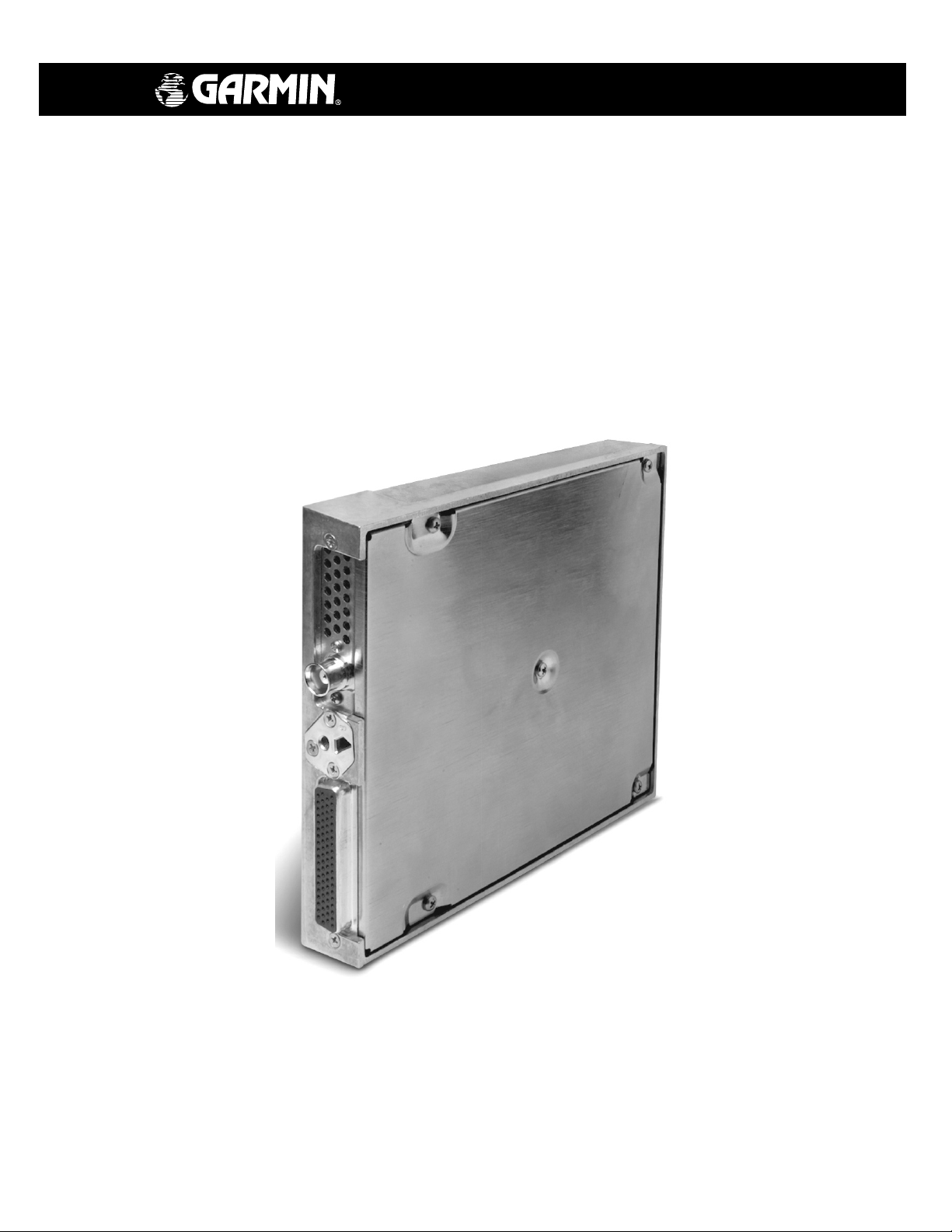
Figure 1-1. GDL 69/69A Unit View
1.3 Equipment Description
The GDL 69/69A is an XM Satellite Radio data link receiver. Two models are available; the GDL 69 is a
weather data receiver. The GDL 69A is the same as the GDL 69 with the addition of XM Satellite Radio
audio entertainment. For display of weather information and control of audio channel and volume, the
GDL 69/69A may be interfaced to the MX20 MFD or 400/500 series units via an RS-232 bus or the
GDU104x via an Ethernet link. Audio volume and channel changes may also be controlled with remotely
mounted optional switches located in the cabin. The GDL 69A is also interfaced to a Garmin audio panel
for amplification and distribution of the audio signal. The XM Satellite Radio antenna receives the XM
Satellite Radio data signal and passes it to the GDL 69/69A.
GDL 69/69A Installation Manual Page 1-1
190-00355-02 Revision E
General Description
1.4 Interfaced Equipment
Accomplishment of installation of the GDL 69/69A under this STC requires previous or concurrent
installation of the following equipment. If installing the model GDL 69, a control display unit is required.
If installing a GDL 69A, a control display unit and audio panel is required.
Table 1-1. Interfaced Equipment List
Software Version
Description Manufacturer
MX20 MFD Control Display Unit Garmin AT Ver. 5.5
GDU 1040 MFD Control Display Unit Garmin 4.01
GDU 1042 MFD Control Display Unit Garmin 5.00
GDU 1043 MFD Control Display Unit Garmin 5.00
GPS 400* Garmin 4.04
OR
OR
SL15M Audio Panel Unit Garmin AT N/A
SL10S Audio Panel Unit
SL10MS Audio Panel Unit Garmin AT N/A
GMA 340 Audio Panel Unit Garmin N/A
GMA 1347 Audio Panel Unit Garmin N/A
GNC 420* Garmin 4.04
GNC 420A* Garmin 4.04
GNS 430* Garmin 4.04
GNS 430A* Garmin 4.04
GPS 500* Garmin 5.04
GNS 530* Garmin 5.04
GNS 530A* Garmin 5.04
SL15 Audio Panel Unit Garmin AT N/A
SL10 Audio Panel Unit Garmin AT N/A
Garmin AT N/A
(Or later FAA
approved version)
* 400/500 series units must use Pilot Guide Addendum 190-00140-13 Revision D, or later.
400/500 series units may be connected to a GDL 69A. The 400/500 series units do not have audio
control capabilities, but the aircraft may be provisioned with a GDL 69A and wiring for future
400/500 series upgrade that will provide audio control and display.
1.5 Audio Entertainment Installation Limitations
The GDL 69A XM Satellite Radio audio entertainment may be installed to all passenger locations for all
aircraft on the STC Approved Model List (AML). XM audio entertainment to crew locations depends on
aircraft installation, which must meet requirements of 14 CFR §23.1431(e).
For purpose of this STC, 14 CFR §23.1431(e) requires that each pilot station must be able to hear the
aircraft’s stall warning horn with the entertainment system audio set to the maximum pilot controllable
setting. This also applies to aircraft with a gear extension warning horn. Aircraft which have electric
stall/gear warning may utilize the GDL 69A audio suppression input to turn off the music during an
event. For these installations, the XM audio may be provided to the crew locations.
For aircraft installations with non-electric stall/gear warning horns, this STC does not provide data for
installation of audio entertainment to crew locations. The GDL 69A audio entertainment may not be
wired to crew locations without a separate evaluation that is beyond the scope of this STC. It is possible
for installers to seek evaluation and approval of an alternate installation by means of the field approval
process. Each installation or aircraft type must be evaluated for compliance with 14 CFR §23.1431(e).
This evaluation may determine that the required horns can be heard satisfactorily without disabling the
GDL 69A audio entertainment to the crew.
Page 1-2 GDL 69/69A Installation Manual
Revision E 190-00355-02

General Description
1.6 XM Satellite Radio
Welcome to the Next Generation of Radio. America's most popular satellite radio service gives you the
power to choose what you want to hear - wherever and whenever you want it around the Continental
United States.
XM Satellite Radio provides commercial-free music channels, channels of news, sports, talk and
entertainment, dedicated channels of instant traffic and weather, the deepest play list in the industry with
access to over 2 million titles, and coast-to-coast coverage. XM features digital quality audio.
Subscriptions to XM Satellite Radio weather and audio entertainment services are required before the
GDL 69/69A can be activated for the first use. Refer to Section 4.5 for instructions for activating your
unit.
NOTE
It is prohibited to copy, decompile, disassemble, reverse engineer, or manipulate any technology
incorporated in receivers compatible with the XM Satellite Radio system. Furthermore, the
AMBE(R) voice compression software included in this product is protected by intellectual
property rights including patent rights, copyrights, and trade secrets of Digital Voice Systems,
Inc. The user of this or any other software contained in an XM Satellite Radio is explicitly
prohibited from attempting to copy, decompile, reverse engineer, or disassemble the object code,
or in any other way convert the object code into human-readable form. The software is licensed
solely for use within this product.
1.7 Interface Summary
The following list is an interface summary for the GDL 69/69A units. Note that the GDL 69 does not
have the audio interface.
• 3 RS-232 Inputs/Outputs
• 4 Ethernet Inputs/Outputs
• 5 Audio Discrete Control Inputs (Volume Up, Volume Down, Channel Up, Channel Down,
Mute)
• 6 Audio Suppression Inputs (3 Active High, 3 Active Low)
• 1 Stereo Audio Output (Left Audio, Right Audio with internal volume control)
• 1 Remote Power On/Off Discrete Input
• 2 Other Discrete Inputs (Reserved for Future Use)
• Configuration Module (for storing aircraft configuration data)
• Aircraft Power Input (Power-on controlled by aircraft avionics power bus)
GDL 69/69A Installation Manual Page 1-3
190-00355-02 Revision E
General Description
1.8 Technical Specifications
The GDL 69/69A and GA 55/GA55A XM antenna are PMA approved and there is no applicable TSO.
The GA 57 GPS/WAAS – XM antenna is TSO authorized under TSO-c144. It is the responsibility of
those desiring to install this equipment either on or within a specific type of class of aircraft to determine
that the aircraft installation standards are within the prescribed standards. The following table presents
general environmental specifications. For detailed specifications, see the Environmental Qualification
form in Appendix B.
Table 1-2. GDL 69/69A Specifications
GDL 69/69A Characteristics Specification
Operating Temperature Range -55° C to +70° C
Input Voltage Range 9.0 to 33.0 VDC
Software Compliance RTCA DO-178B Level D
Environmental Compliance RTCA DO-160D
Table 1-3. GA 55, GA 55A, GA 57 Specifications
GA 55, GA 55A, GA 57 Characteristics Specification
Operating Temperature Range -55° C to +85° C
Input Voltage Range Power provided by GDL 69/69A.
Software Compliance None
Environmental Compliance RTCA DO-160D
Table 1-4. GDL 69/69A Unit Dimensions
Characteristic Specification
Width 1.05 inches (2.66 cm)
Height 6.15 inches (15.62 cm)
Depth (Rack w/ Connectors) 7.20 inches (18.26 cm)
Unit Weight (GDL 69A) 1.86 lbs (0.84 kg)
Unit (GDL 69A) and Remote Rack Weight 2.83 lbs (1.27 kg)
NOTE
See Table 2-8 outlining weights for the GDL 69, GDL 69A, remote rack, and modular rack.
Page 1-4 GDL 69/69A Installation Manual
Revision E 190-00355-02
General Description
6.91 [175.6]
0.73 [18.6]
0.73 [18.49]
1.23 31.1
WITH DIMPLES
1.20 30.5
WITHOUT DIMPLES
8.26 [209.8]
7.9 [200.9]
6.43
[163.2]
3.57 [90.7]
CENTER OF
GRAVITY
0.37
[9.40]
3.98 [101.1]
CENTER OF GRAVITY
1.60
[40.53]
8.74 [221.9]
4.46 [113.22]
0.49 [12.4]
Figure 1-2. GDL 69/69A Remote Rack Unit Dimensions
1.48
[37.7]
ANTENNA
J691
7.26 184.4
175.3
6.90
TYP
.60 15.2
.36 TYP 9.1
.48 TYP
6.30 160.0
3.00 76.2
4.30 109.2
12.2
.48 TYP 12.2
.36 TYP 9.1
4X .38 9.6
4X 3.73 94.7
7.65 194.3
8.73 221.8
ANTENNA
J691
Figure 1-3. GDL 69/69A Modular Rack Unit Dimensions
GDL 69/69A Installation Manual Page 1-5
190-00355-02 Revision E
General Description
1.8.1 General Antenna Requirements
Garmin recommends the Garmin XM antenna shown in the Table 1-5 below. These antennas are
approved with the certification of the GDL 69/69A. However, any equivalent XM antenna with
specifications listed in Table 1-6 should work with the GDL 69/69A. Antennas must provide protection
from direct lightning strikes. This STC does not support installations of equivalent antennas.
Table 1-5. XM Antennas
Model Part Number Description Mounting Configuration
GA 55 011-01033-00 XM Antenna Stud mount Tear-drop form factor
GA 55A 011-01153-00 XM Antenna Thru-mount (ARINC 743 style mount)
GA 57 011-01032-00 GPS/WAAS + XM Antenna Thru-mount (ARINC 743 style mount)
Table 1-6. XM Satellite Radio Antenna Minimum Requirements
Frequency Range 2332.5 to 2345 MHz
Gain (Typical) 24 dB ± 1 dB**
Noise Figure <1.2 dB
Nominal Output Impedance 50 ohms
Supply Voltage 3.6 to 5.5 VDC
Supply Current (maximum) 55 mA
Operating Temperature Gain -50 to +85°C
** For each 1 dB gain over 24 dB, add 1 dB of attenuation into the antenna cable path between
the antenna and the GDL 69/69A.
Table 1-7. GA 55, GA 55A, GA 57 XM Antenna Specifications
Frequency Range 2332.5 to 2345 MHz
Gain 25 ± 2 dB
Noise Figure <1.2 dB
Nominal Output Impedance 50 ohms
Supply Voltage 3.6 to 5.5 VDC
Supply Current 40 to 55 mA
Operating Temperature Range -50 to +85 ° C
Output Connector TNC
Page 1-6 GDL 69/69A Installation Manual
Revision E 190-00355-02
General Description
1.9 Reference Documents
The following publications are sources of additional information for installing the GDL 69/69A. Before
installing the GDL 69/69A, the technician should read all referenced materials applicable to the
installation along with this manual.
Table 1-8. Referenced Publications
Manufacturer Part Number Document
Garmin 190-00149-01 GMA 340 Audio Panel Installation Manual
Garmin 190-00303-20 GMA 1347 Audio Panel Installation Manual
Garmin 190-00181-02 500 Series Installation Manual
Garmin 190-00140-02 400 Series Installation Manual
Garmin 190-00140-13 400/500 Series Garmin Optional Displays
Garmin 190-00303-01 GDU 1040 Installation Manual
Garmin 190-00522-01 GA 55A, GA 56A and GA 57 Antenna Installation Manual
Garmin 190-00355-04 XM™ Satellite Radio Activation Instructions
Garmin AT 560-1025-( ) MX20 Installation Manual
Garmin AT 560-0979-( ) SL15 Audio Panel Installation Manual
Garmin AT 560-0978-( ) SL10 Audio Panel Installation Manual
1.10 Certification
The GDL 69 and GDL 69A XM Satellite Radios and the XM Satellite Radio Antenna have Parts
Manufacturing Approval (PMA) for the aircraft listed on the STC Approved Mode List (AML).
1.10.1 TSO/JTSO Compliance
The GA 57 is TSO-C144 authorized. There are no other applicable TSO standards.
1.10.2 Other Regulatory Criteria
The GDL 69/69A and GA 55 and GA 55A are PMA authorized.
1.11 Unpacking Unit
Carefully unpack the equipment and make a visual inspection of the unit for evidence of damage incurred
during shipment. If the unit is damaged, notify the carrier and file a claim. To justify a claim, save the
original shipping container and all packing materials. Do not return the unit to Garmin until the carrier
has authorized the claim.
Retain the original shipping containers for return shipments. If the original containers are not available, a
separate cardboard container should be prepared that is large enough to accommodate sufficient packing
material to prevent movement.
1.12 Warranty Statement
Limited Warranty
This Garmin product is warranted to be free from defects in materials or workmanship for two years from
the date of purchase. Within this period, Garmin will at its sole option, repair or replace any components
that fail in normal use. Such repairs or replacement will be made at no charge to the customer for parts or
labor, provided that the customer shall be responsible for any transportation cost. This warranty does not
cover failures due to abuse, misuse, accident or unauthorized alteration or repairs.
THE WARRANTIES AND REMEDIES CONTAINED HEREIN ARE EXCLUSIVE AND IN LIEU OF
ALL OTHER WARRANTIES EXPRESS OR IMPLIED OR STATUTORY, INCLUDING ANY
LIABILITY ARISING UNDER ANY WARRANTY OF MERCHANTABILITY OR FITNESS FOR A
PARTICULAR PURPOSE, STATUTORY OR OTHERWISE. THIS WARRANTY GIVES YOU
SPECIFIC LEGAL RIGHTS, WHICH MAY VARY FROM STATE TO STATE.
GDL 69/69A Installation Manual Page 1-7
190-00355-02 Revision E

General Description
IN NO EVENT SHALL GARMIN BE LIABLE FOR ANY INCIDENTAL, SPECIAL, INDIRECT OR
CONSEQUENTIAL DAMAGES, WHETHER RESULTING FROM THE USE, MISUSE, OR
INABILITY TO USE THIS PRODUCT OR FROM DEFECTS IN THE PRODUCT. Some states do not
allow the exclusion of incidental or consequential damages, so the above limitations may not apply to
you.
Garmin retains the exclusive right to repair or replace the unit or software or offer a full refund of the
purchase price at its sole discretion. SUCH REMEDY SHALL BE YOUR SOLE AND EXCLUSIVE
REMEDY FOR ANY BREACH OF WARRANTY.
To obtain warranty service, contact your local Garmin Authorized Service Center. For assistance in
locating a Service Center near you, call Garmin Customer Service at one of the numbers shown below.
Products sold through online auctions are not eligible for rebates or other special offers from Garmin.
Online auction confirmations are not accepted for warranty verification. To obtain warranty service, an
original or copy of the sales receipt from the original retailer is required. Garmin will not replace missing
components from any package purchased through an online auction.
Garmin International, Inc. Garmin (Europe) Ltd.
1200 East 151
st
Street Unit 5, The Quadrangle, Abbey Park Industrial Estate
Olathe, Kansas 66062, U.S.A. Romsey, SO51 9DL, U.K.
Phone: 913/397.8200 Phone: 44/1794.519944
FAX: 913/397.0836 FAX: 44/1794.519222
Page 1-8 GDL 69/69A Installation Manual
Revision E 190-00355-02
Installation Procedure
2 INSTALLATION
2.1 Introduction
This section provides hardware equipment information for installing the GDL 69/69A, cabling for the
XM antenna (GA 55, GA 55A, or GA 57), and related hardware. Installation of the GDL 69/69A should
follow the aircraft TC or STC requirements. For interconnects with the GDU 104x, MX20 MFD or
400/500 series refer to Appendix D of this manual. For installation information on the GDU 104x, MX20
MFD or 400/500 series, refer to their installation manuals.
Installation of the XM antennas is covered under separate Garmin GA Antenna AML STC.
2.2 Pre-Installation Information
Always follow acceptable avionics installation practices per FAA Advisory Circulars (AC) 43.13-1B,
43.13-2A, or later FAA approved revisions of these documents.
Follow the installation procedure in this manual as it is presented for a successful installation. Read the
entire manual before beginning the procedure. Prior to installation, consider the structural integrity of the
GDL 69/69A installation as defined in AC 43.13-2A, Chapter 1 and evaluate the necessity for audio
suppression inputs in accordance with the GDL 69A Audio Limitations in Section 6. Perform the post
installation checkout before closing the work area in case problems occur.
Complete an electrical load analysis in accordance with AC 43.13-1B, Chapter 11, on the aircraft prior to
starting modification to ensure aircraft has the ability to carry the GDL 69/69A load. Refer to Section 2.8
for the power consumption of each GDL 69/69A mode of operation. Document the results of the
electrical load analysis on FAA Form 337.
2.3 Installation Materials
2.3.1 Configurations Available
Each of the GDL 69 and 69A can be ordered in different kits, each of which may contain components
listed in the following table.
Table 2-1. Kit Contents
Description Part Number
GDL 69 XM Weather Data Receiver 011-00986-00
GDL 69A XM Weather/Audio Data Receiver 011-00987-00
Back Plate Assembly 011-00796-35
Remote Mount Rack GDL 69 115-00658-00
Connector Kit Assembly 011-00997-00
Configuration Module Assembly 011-00979-00
GA 55 XM Antenna 011-01033-00
GA 55A XM Antenna 011-01153-00
OR
GA 57 XM Antenna 011-01032-00
Rack Nut Plate, 2 POS 011-00915-00
Modular Rack 115-00411-00
GDL 69/69A Installation Manual Page 2-1
190-00355-02 Revision E
Installation Procedure
2.3.2 Equipment Required But Not Supplied
• Wire: MIL-W-22759/16 or equivalent
• Shielded Wire: MIL-C-27500 or equivalent
• Hardware for Remote Mount Rack:
Vertical Mount: Four #8-32 Pan Head Screws (MS35206, AN526 or equivalent)
Horizontal Mount: Four #6-32 x 100° Counter-Sunk Flat Head Screw (MS24693, AN507R or
equivalent)
• Circuit Breaker: Appropriate for selected wire size
2.4 Equipment Mounting
2.4.1 Rack Location and Installation
The GDL 69/69A may be mounted in a pressurized or unpressurized location. The GDL 69/69A does not
require forced-air cooling; when mounting, avoid locating the GDL 69/69A near sources that produce
high levels of heat. The GDL 69/69A has two mounting rack options available, the remote rack and the
modular rack for use with the G1000 system.
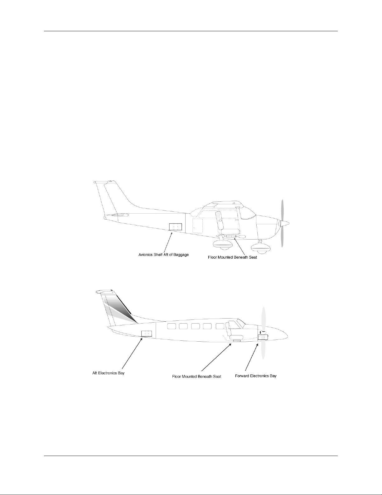
Figure 2-1. Suggested Mounting Locations for Remote Rack
Page 2-2 GDL 69/69A Installation Manual
Revision E 190-00355-02
Installation Procedure
2.4.2 Remote Mount Rack
The remote mount rack can be installed in a variety of locations, such as the electronics bay, behind the
instrument panel, under the seat or behind the rear baggage area. Leave sufficient clearance between the
GDL 69/69A and any obstruction. Install the rack in accordance with AC43.13-2A Chapter 2 Radio
Installations. The remote mount rack should be mounted to a surface known to have sufficient structural
integrity to withstand additional inertial forces imposed by a 1.86 pound unit (1.72 lbs. for GDL 69). If it
is necessary to build a shelf or bracket to mount the GDL 69/69A rack or if is not certain that the chosen
location is of sufficient structural integrity, refer to Appendix C. Refer to Figure 1-2 for the GDL 69/69A
remote mount rack dimensions. The rack can be mounted vertically using four 8-32 pan head screws
(MS35206, AN526 or equivalent.) It can also be mounted horizontally using four 6-32 100° counter-sunk
flathead screws (MS24693, AN507R or equivalent.) Ensure that the rack has a ground path to the
airframe by having at least one mounting screw in contact with the airframe to minimize radiated
electromagnetic interference (EMI).
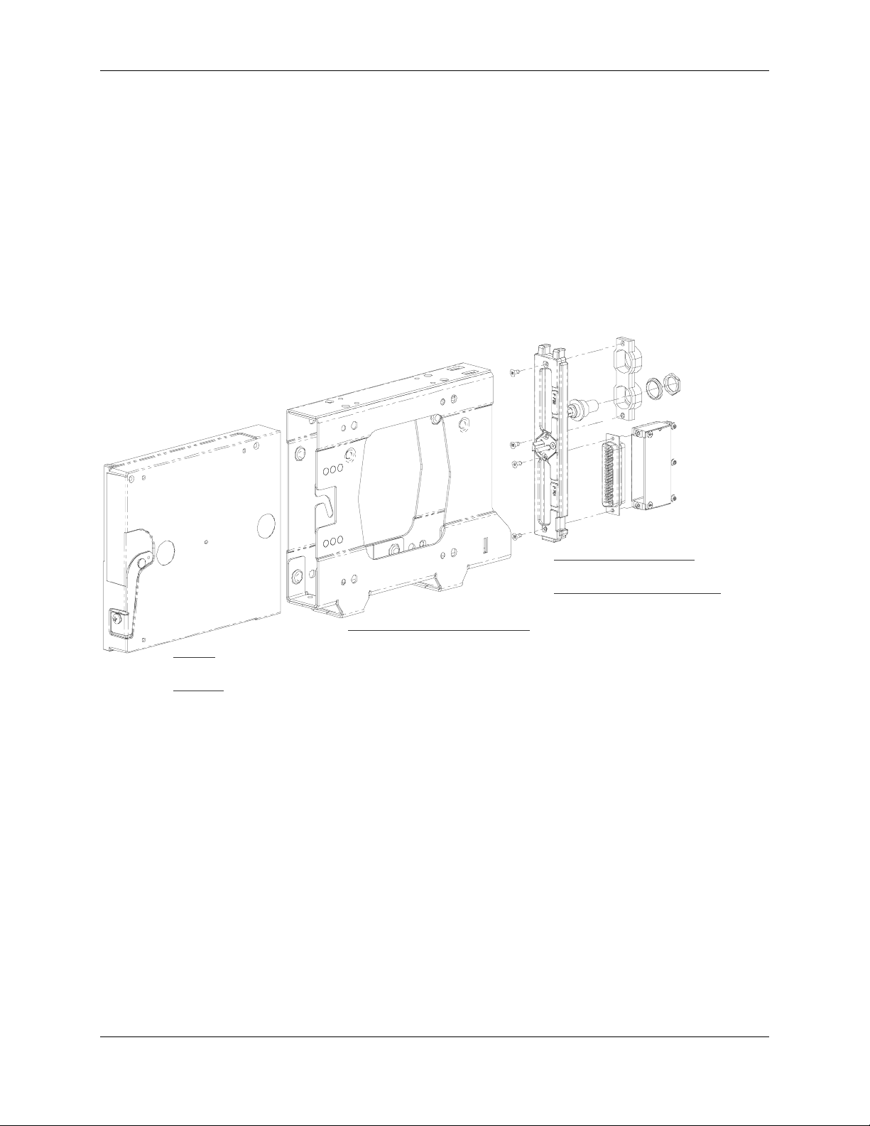
BACK PLATE ASSEMBLY
P/N: 011-00796-35
CONNECTOR KIT ASSEMBLY
P/N: 011-00997-00
GDL 69 REMOTE MOUNT RACK
GDL 69
P/N: 011-00986-00
GDL 69A
P/N: 001-00987-00
P/N: 115-00658-00
Figure 2-2. GDL 69/69A Remote Mount Rack
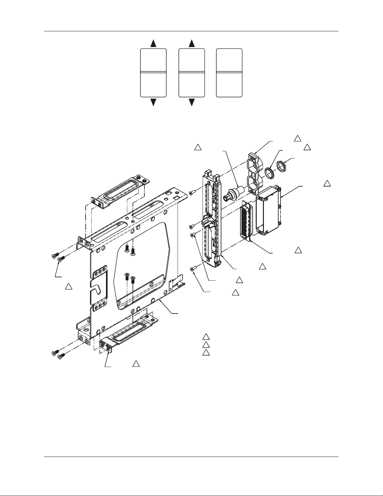
2.4.3 G1000 Modular Rack
The G1000 modular rack is used to install the GDL 69/69A in the standard G1000 integrated avionics
system rack. This modular rack may be mounted behind the instrument panel or in the avionics bay. Refer
to Figure 1-3 for the GDL 69/69A G1000 modular rack dimensions. This STC covers the installation of
the GDL 69/69A modular rack into the installed G1000 integrated avionics system rack, but does not
cover the installation of the G1000 integrated avionics system rack.
2.4.4 Remote Switches
Installation of rocker switches should be made on a flat surface and located at a convenient location
within the cabin. Each rocker switch installed must be properly marked of its function. Use of rocker
switches vs. toggle switches will prevent the possibility of raising and lowering the volume at the same
time or raising and lowering the channels at the same time. Wire used for discrete switches should be 24
AWG (MIL Spec M22759) and should be routed as appropriate, avoiding kinking or sharp bends. Figure
2-3 shows typical rocker switches.
GDL 69/69A Installation Manual Page 2-3
190-00355-02 Revision E
Installation Procedure
V
Channel
olume Mute
Figure 2-3. Typical Rocker Switches
1
212-00022-00
PART OF 330-00053-02
3
1
011-00950-04
3
211-63207-10
8 PLCS
2
1
330-00053-02
211-63234-10
3 PLCS
211-63234-12
2 PLCS
125-00059-04
1
3
125-00097-00
330-00185-78
1
115-00411-00
NOTES:
1. PART OF 011- 00796-35 BACK PLATE ASSEMBLY
2. PART OF 011- 00915-00 NUT PLATE KIT
3. PART OF 011- 00997-00 CONNECTOR KIT
115-00657-00
2 PLCS
MAY ALTERNAT ELY USE P/N 115- 00511-00
(PART OF KIT 011- 01148-00)
2
4. APPLY THREAD LOCKING COMPOUND TO ALL THREADED FASTENERS.
Figure 2-4. Modular Rack for the G1000
Page 2-4 GDL 69/69A Installation Manual
Revision E 190-00355-02
Installation Procedure
2.5 Cabling and Wiring
Wiring should be installed in accordance with AC 43.13-1B Chapter 11. When wire separation cannot be
achieved, the following issues should be addressed:
• The cable harness should not be located near flight control cables and control, high electrical
capacity lines or fuel lines
• The cable harness should be located in a protected area of the aircraft
• Do not route cable near high-energy sources
Refer to the interconnection diagrams in Appendix D for the appropriate wiring. Once the cable
assemblies have been made, attach the cable connector to the rear of the rack. Route the wiring bundle as
appropriate. Use 22 or 24 AWG wire for all connections except for power. Use 22 AWG for
power/ground. Avoid sharp bends.
After the cable assemblies are made assemble the backshell as shown in Figure 2-6. Then install the
backshell connector to the rear plate using the screws provided in the connector kit. After the rack is
installed, assemble the rear plate into the rack.
2.5.1 Wiring Harness
Allow adequate space for installation of cables and connectors. The installer supplies and fabricates all of
the cables. Except for the antenna connection, all electrical connections are made through a 78-pin DSubminiature connector provided by Garmin. Construct the wiring harness according to the information
contained in this and the following sections. Cable lengths will vary depending upon installation. Strip
all wires going to the 78-pin D-Sub connector 1/8”. Insert the wire into the pin and crimp with one of the
recommended (or equivalent) crimping tools. Insert the pin into the 78-pin D-Sub connector housing
location as specified by the interconnect drawing in Appendix D. Verify the pin is properly engaged into
the connector by gently tugging on the wire. Route and secure the cable run from the GDL 69/69A to the
other units away from sources of electrical noise.
Section 3 defines the electrical characteristics of all input and output signals. Required connectors and
associated hardware are supplied with the connector kit. See Appendix D for interconnect wiring
diagrams.
CAUTION
Check wiring connections for errors before inserting the GDL 69/69A
into the rack or mounting bracket. Incorrect wiring could cause
component damage.
Table 2-2. Pin Contact Part Numbers
Wire Gauge
Garmin P/N 336-00021-00
Military P/N M39029/58-360
AMP 204370-2
Positronic MC8522D
ITT Cannon 030-2042-000
78 pin connectors (P691)
22-28 AWG
GDL 69/69A Installation Manual Page 2-5
190-00355-02 Revision E
 Loading...