

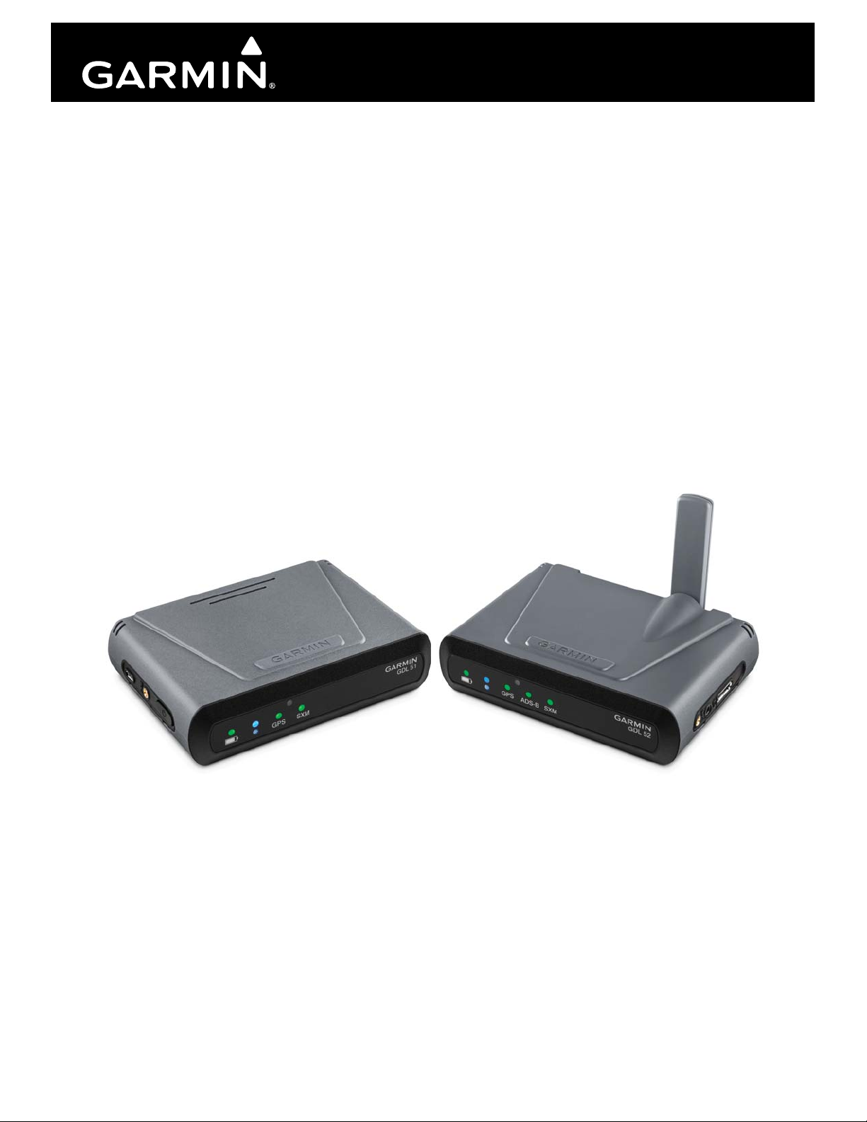
GDL 50(R)/51(R)/52(R)
Data Link
Installation Manual
190-02087-10 August, 2018 Revision 2
© 2018
Garmin Ltd. or its subsidiaries
All Rights Reserved
Except as expressly provided herein, no part of this manual may be reproduced, copied,
transmitted, disseminated, downloaded or stored in any storage medium, for any purpose without
the express prior written consent of Garmin. Garmin hereby grants permission to download a
single copy of this manual and of any revision to this manual onto a hard drive or other electronic
storage medium to be viewed and to print one copy of this manual or of any revision hereto,
provided that such electronic or printed copy of this manual or revision must contain the complete
text of this copyright notice and provided further that any unauthorized commercial distribution of
this manual or any revision hereto is strictly prohibited.
Garmin International, Inc.
1200 E. 151st Street
Olathe, KS 66062 USA
Aviation Panel-Mount Technical Support Line (Toll Free) 1.888.606.5482
Garmin (Europe) Ltd.
Liberty House, Hounsdown Business Park
Southampton, Hampshire SO40 9LR U.K.
Garmin aviation support and warranty information can be found at www.flygarmin.com.
RECORD OF REVISIONS
Revision
1 08/04/17 Initial Release
2 08/15/18 Added GDL 50(R) info
Revision
Date
Description
190-02087-10 GDL 50(R)/51(R)/52(R) Installation Manual
Rev. 2 Page A

CURRENT REVISION DESCRIPTION
Revision
2
Page
Number(s)
ii Front Added GDL 50/50R references to note
iv Front Added symbols for Australian and Canadian compliance
1-1–1-5 1 Added GDL 50/50R info and updated throughout Section 1
2-1–2-3,
2-8, 2-9
3-1,
3-3–3-6
4-1–4-4 4 Added GDL 50/50R info and updated throughout Section 4
A-1–A-7 A Updated to include GDL 50/50R units and current drawings
B-1–B-3 B Updated to include GDL 50/50R units
Section
Number
2 Added GDL 50/50R info and updated throughout Section 2
3 Added GDL 50/50R info and updated throughout Section 3
Description of Change
INFORMATION SUBJECT TO EXPORT CONTROL LAWS
This document may contain information which is subject to the Export Administration Regulations
(“EAR”) issued by the United States Department of Commerce (15 CFR, Chapter VII Subchapter C) and
which may not be exported, released or disclosed to foreign nationals inside or outside the United States
without first obtaining an export license. The preceding statement is required to be included on any and all
reproductions in whole or in part of this manual.
190-02087-10 GDL 50(R)/51(R)/52(R) Installation Manual
Rev. 2 Page i
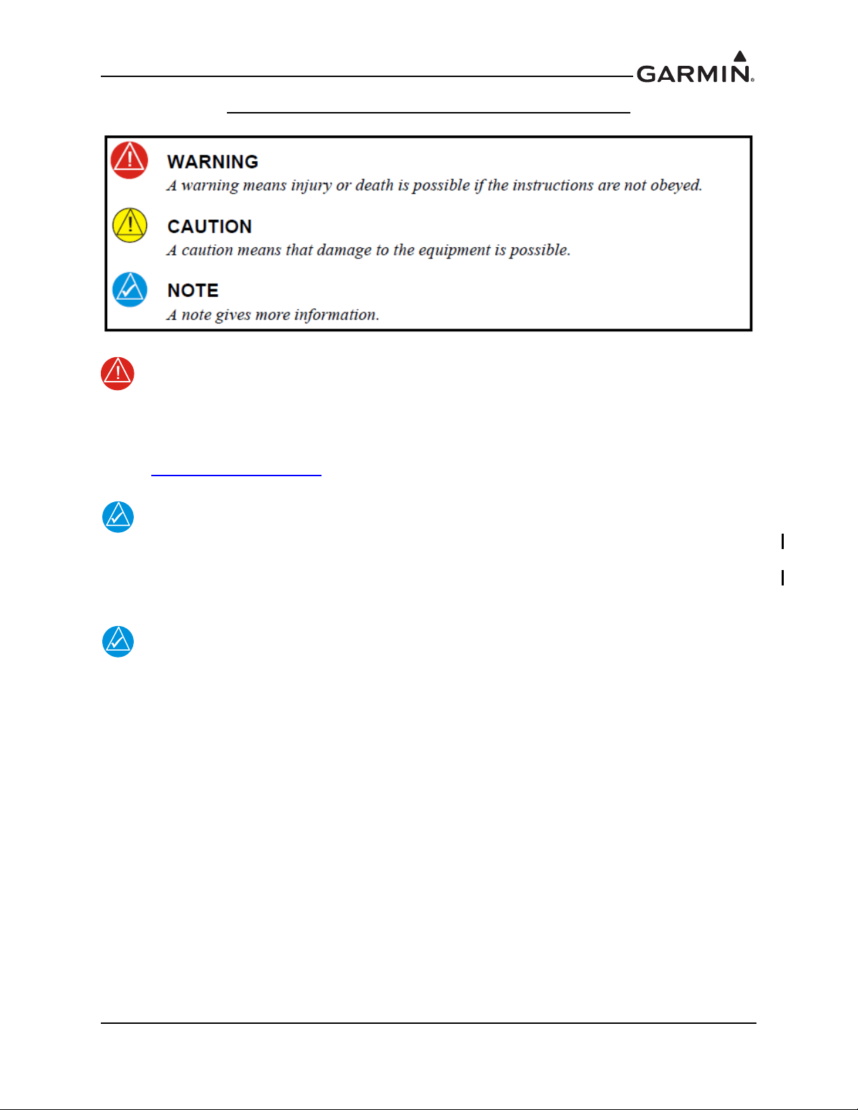
DEFINITIONS OF WARNINGS, CAUTIONS, AND NOTES
WARNING
NOTE
NOTE
This product, its packaging, and its components contain chemicals known to the State of
California to cause cancer, birth defects, or reproductive harm. This notice is being
provided in accordance with California's Proposition 65. If you have any questions or
would like additional information, please refer to our web site at
www.garmin.com/prop65.
References to GDL 5X in this installation manual refer to the Garmin GDL 50, GDL 51
and GDL 52 unless specifically noted otherwise. References to GDL 5XR in this
installation manual refer to the Garmin GDL 50R, GDL 51R and GDL 52R unless
specifically noted otherwise.
The Bluetooth® word mark and logos are registered trademarks owned by Bluetooth SIG,
Inc. and any use of such marks by Garmin is under license. iPad®, iPhone®, iPod®, and
iPod touch are trademarks of Apple Inc., registered in the USA and other countries.
Android™ is a trademark of Google Inc. Sirius, XM, SiriusXM, and all related marks and
logos are trademarks of Sirius XM Radio Inc. All other marks, channel names, and logos
are the property of their respective owners. All rights reserved.
190-02087-10 GDL 50(R)/51(R)/52(R) Installation Manual
Rev. 2 Page ii

SOFTWARE LICENSE AGREEMENT
BY USING THE DEVICE, COMPONENT OR SYSTEM MANUFACTURED OR SOLD BY GARMIN
(“THE GARMIN PRODUCT”), YOU AGREE TO BE BOUND BY THE TERMS AND CONDITIONS
OF THE FOLLOWING SOFTWARE LICENSE AGREEMENT. PLEASE READ THIS AGREEMENT
CAREFULLY. Garmin Ltd. and its subsidiaries (“Garmin”) grants you a limited license to use the
software embedded in the Garmin Product (the “Software”) in binary executable form in the normal
operation of the Garmin Product. Title, ownership rights, and intellectual property rights in and to the
Software remain with Garmin and/or its third-party providers. You acknowledge that the Software is the
property of Garmin and/or its third-party providers and is protected under the United States of America
copyright laws and international copyright treaties. You further acknowledge that the structure,
organization, and code of the Software are valuable trade secrets of Garmin and/or its third-party providers
and that the Software in source code form remains a valuable trade secret of Garmin and/or its third-party
providers. You agree not to reproduce, decompile, disassemble, modify, reverse assemble, reverse
engineer, or reduce to human readable form the Software or any part thereof or create any derivative works
based on the Software. You agree not to export or re-export the Software to any country in violation of the
export control laws of the United States of America.
190-02087-10 GDL 50(R)/51(R)/52(R) Installation Manual
Rev. 2 Page iii

1. FCC Compliance
FCC ID: IPH-02895
This device complies with part 15 of the FCC Rules. Operation is subject to the following two conditions:
(1) this device may not cause harmful interference, and (2) this device must accept any interference
received, including interference that may cause undesired operation.
This equipment has been tested and found to comply with the limits for a Class B digital device, pursuant
to part 15 of the FCC rules. These limits are designed to provide reasonable protection against harmful
interference in a residential installation. This equipment generates, uses, and can radiate radio frequency
energy and may cause harmful interference to radio communications if not installed and used in
accordance with the instructions. However, there is no guarantee that interference will not occur in a
particular installation. If this equipment does cause harmful interference to radio or television reception,
which can be determined by turning the equipment off and on, the user is encouraged to try to correct the
interference by one of the following measures:
• Reorient or relocate the receiving antenna.
• Increase the separation between the equipment and the receiver.
• Connect the equipment into an outlet that is on a different circuit from the unit.
• Consult the dealer or an experienced radio/TV technician for help.
2. IC
IC: 1792A-02895
Innovation, Science and Economic Development Canada Compliance
This device complies with Innovation, Science and Economic Development Canada license-exempt RSS
standard(s). Operation is subject to the following two conditions: (1) this device may not cause
interference, and (2) this device must accept any interference, including interference that may cause
undesired operation of the device.
Innovation, Sciences et Développment économique Canada - Conformité
Cet appareil est conforme aux normes RSS sans licence du ministére Innovation, Sciences et
Développement économique Canada. Son fonctionnement est soumis aux deux conditions suivantes : (1)
ce périphérique ne doit pas causer d’interférences et (2) doit accepter toute interférence, y compris les
interférences pouvant entraîner un fonctionnement indésirable de l’appareil.
M/N: A02895
190-02087-10 GDL 50(R)/51(R)/52(R) Installation Manual
Rev. 2 Page iv
TABLE OF CONTENTS
PARAGRAPH PAGE
Section 1 General Description ...........................................................................1-1
1.1 Introduction...................................................................................................................... 1-1
1.2 Equipment Description .................................................................................................... 1-1
1.3 Technical Specifications .................................................................................................. 1-3
1.4 Reference Documents ...................................................................................................... 1-5
Section 2 Installation Overview.........................................................................2-1
2.1 Introduction...................................................................................................................... 2-1
2.2 Installation Materials ....................................................................................................... 2-1
2.3 Available Accessories...................................................................................................... 2-1
2.4 Installation Considerations .............................................................................................. 2-3
2.5 GDL 5X/5XR Installation Guidance for Best Wireless Performance ............................. 2-4
2.6 Cabling and Wiring..........................................................................................................2-5
2.7 Cooling Air ...................................................................................................................... 2-6
2.8 Configuration, and Adjustment Options.......................................................................... 2-6
2.9 Front Panel....................................................................................................................... 2-7
2.10 Updating Software ......................................................................................................... 2-8
2.11 Noise .............................................................................................................................. 2-9
2.12 Mounting Requirements ................................................................................................ 2-9
Section 3 Installation Procedure........................................................................3-1
3.1 Unpacking Unit................................................................................................................ 3-1
3.2 Wiring Harness Installation ............................................................................................. 3-1
3.3 Backshell Assembly......................................................................................................... 3-2
3.4 Coax Cable Installation.................................................................................................... 3-2
3.5 Equipment Mounting ....................................................................................................... 3-2
3.6 Continued Airworthiness ................................................................................................. 3-2
3.7 Antenna Installation......................................................................................................... 3-3
3.8 Non-Garmin Antennas..................................................................................................... 3-4
3.9 Garmin Antennas .............................................................................................................3-5
3.10 Post Installation Checkout ............................................................................................. 3-6
Section 4 System Interconnects .........................................................................4-1
4.1 Pin Function List.............................................................................................................. 4-1
Appendix A Outline and Installation Drawings .............................................A-1
Appendix B Interconnect Drawings................................................................. B-1
190-02087-10 GDL 50(R)/51(R)/52(R) Installation Manual
Rev. 2 Page v
1 GENERAL DESCRIPTION
NOTE
1.1 Introduction
This manual provides installation guidance, but does not provide any approval, which may be required in
some cases, to install these devices in an aircraft. This manual is not a substitute for an approved airframespecific maintenance manual, installation design drawing, or complete installation data package.
Attempting to install equipment by reference to this manual alone and without first planning or designing
an installation specific to your aircraft may compromise your safety and is not recommended. The content
of this manual assumes use by competent and qualified avionics engineering personnel and/or avionics
installation specialists using standard aviation maintenance practices in accordance with Title 14 of the
Code of Federal Regulations and other relevant accepted practices. This manual is not intended for use by
individuals who do not possess the competencies and abilities set forth above.
Garmin recommends installation of the GDL 5X/5XR by a Garmin-authorized installer.
To the extent allowable by law, Garmin will not be liable for damages resulting from
improper or negligent installation of the GDL 5X/5XR. For questions, please contact
Garmin Product Support at 1-888-606-5482.
1.2 Equipment Description
The Garmin GDL 50/50R/51/51R/52/52R products are not TSO-certified products and have received no
FAA approval or endorsement. These products can provide the following data: GPS, SiriusXM weather/
audio, ADS-B traffic and weather, attitude and pressure to compatible displays and audio devices via
Bluetooth® wireless technology and/or over wired connections.
The GDL 52/52R data link products include internal WAAS-enabled GPS, dual-band ADS-B & SiriusXM
receivers, and attitude & pressure sensors. The GDL 51/51R product provide the same functionality except
for the dual band ADS-B receiver. The GDL 50/50R products provide the same functionality except for the
SiriusXM receiver.
The GDL 5X provide these functions in a portable form factor that includes applicable internal
GPS/SXM/ADS-B antennas, and an internal battery. The GDL 5XR products are remote mount versions
that require external antennas and power connections. No battery is provided in the remote mount
versions.
The GDL 50/50R/52/52R receives Traffic (ADS-B/ADS-R and TIS-B) on both Universal Access
Transceiver (UAT) and 1090 ES (Extended Squitter) frequency bands. When in range of a ground station,
these units will receive FIS-B weather over the UAT link.
The GDL 5X/5XR products provide this information to Garmin® units like the aera 660/795/796, G3X
Touch displays and devices running Garmin Pilot™. These products will request this information over a
Connext® data connection. Please see additional information in the pilot's guide for your display.
190-02087-10 GDL 50(R)/51(R)/52(R) Installation Manual
Rev. 2 Page 1-1
1.2.1 Features Summary
• Internal SXM antenna (51/52 only)
• Internal GPS antenna (5X only)
• Internal ADS-B antenna (50/52 only)
• External SXM antenna port (51/51R/52/52R only)
• External GPS antenna port
• External ADS-B antenna port (50/50R/52/52R only)
• 3.5 mm audio jack (audio out only) (51/52 only)
• 2 RS-232 ports
• Wired audio out (51R/52R only)
• Micro-USB port for charging, power, and SW updates (GDL 5X only)
• Supports Bluetooth Connections to 2 displays + 1 audio device
• Attitude Sensor
• Pressure Sensor
1.2.2 Compatible Displays
The following Garmin devices are compatible with the GDL 5X/5XR units.
• aera 660
• aera 795/796
• G3X Touch Displays (GDU 4XX)
• Garmin Pilot App
1.2.3 Compatible Audio Devices
Although not an exhaustive list, the following Garmin audio panels are compatible with the GDL 5X/5XR
units.
•GMA 245
•GMA 345
• GMA 350c
Additionally, aviation headsets that support the Bluetooth A2DP Profile (audio streaming) should be
compatible with the GDL 5X/5XR products. See the applicable pilot’s guide and headset manual for
additional information.
190-02087-10 GDL 50(R)/51(R)/52(R) Installation Manual
Rev. 2 Page 1-2
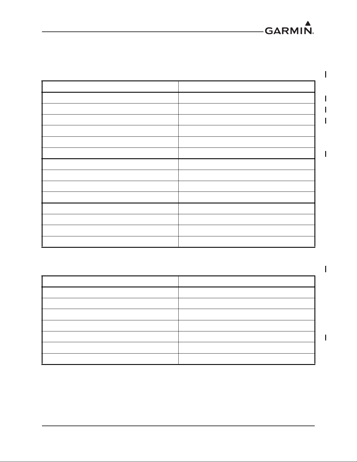
1.3 Technical Specifications
1.3.1 Physical Characteristics
Table 1-1 GDL 5X Physical Characteristics
Characteristic Specification
Height (GDL 51) 1.30 inches (33.0 mm)
Height, Antenna Down (GDL 50/52) 1.50 inches (38.1 mm)
Height, Antenna Up (GDL 50/52) 3.37 inches (85.6 mm)
Width 4.90 inches (124.4 mm)
Depth 3.40 inches (86.4 mm)
Weight, GDL 5X 0.75 lbs (0.34 kg)
Height w/Mounting Bracket 1.51 inches (38.3 mm)
Width w/Mounting Bracket 5.26 inches (133.6 mm)
Depth w/Mounting Bracket 3.52 inches (89.5 mm)
Weight w/Mounting Bracket 0.81 lbs (0.37 kg)
Height w/Mounting Bracket and Non-Slip Pad 1.65 inches (41.9 mm)
Width w/Mounting Bracket and Non-Slip Pad 7.50 inches (190.5 mm)
Depth w/Mounting Bracket and Non-Slip Pad 5.50 inches (139.7 mm)
Weight w/Mounting Bracket and Non-Slip Pad 1.06 lbs (0.48 kg)
Table 1-2 GDL 5XR Physical Characteristics
Characteristic Specification
Height 1.60 inches (40.6 mm)
Width 6.10 inches (154.9 mm)
Depth 5.00 inches (127.0 mm)
Depth w/Connector 6.46 inches (164.2 mm)
Weight, GDL 50R 0.77 lbs (0.35 kg)
Weight, GDL 51R 0.78 lbs (0.35 kg)
Weight, GDL 52R 0.83 lbs (0.38 kg)
190-02087-10 GDL 50(R)/51(R)/52(R) Installation Manual
Rev. 2 Page 1-3

1.3.2 General Specifications
Table 1-3. General Specifications
Characteristic Specification
Operating Voltage 14/28 VDC refer to Table 1-4 for detailed power requirements
-20°C to +60°C (operation)
Temperature Range
Maximum Altitude 55,000 ft
Headphone Output
Bluetooth Connectivity
-20°C to +30°C (storage)
-20°C to +50°C (short term storage)
0°C to +40°C (battery charging range)
Output amplifiers: 1 Stereo 3.5mm output for lineout/consumer audio
Power, Load, and Distortion: 20 mW into a 16 Ω Load with < 1.0% THD
Typical Operating Distortion: <1% THD+N
3dB Frequency Response Bandwidth: 20 Hz to 20 kHz for Music
Typical Output Voltage @ 100% Output: 1.0 VRMS into a 600 Ω load
Bluetooth 3.00 Compliant, allows music and connections to Connext
capable displays. Bluetooth supports SPP and A2DP.
The GDL stores 14 paired devices and overwrites the least recently
connected device when a new device is paired. Only 1 Bluetooth audio
connection is allowed at one time.
USB Port (GDL 5X only)
The Micro-USB port is rated for 10W of input power (only in charging
mode). Max input current is 2A. USB 2.0 compatible and mass storage
mode available.
190-02087-10 GDL 50(R)/51(R)/52(R) Installation Manual
Rev. 2 Page 1-4

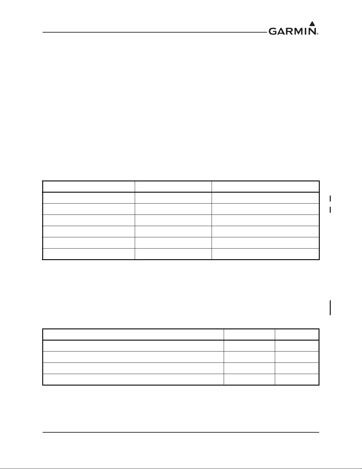
1.3.3 Power Requirements
Table 1-4 lists the power requirements for the GDL 5X/5XR units. Aircraft power input voltage range is
10-32 VDC. The GDL 5X/5XR will operate down to emergency voltage (9V). USB input voltage range is
5V +/- 0.25V.
Table 1-4. Power Specifications
Unit
GDL 50
GDL 50R
GDL 51
GDL 51R
GDL 52
GDL 52R
Aircraft
Power - Unit
On, Not
Charging
0.17A @14V 0.35A @ 14V 0.82A @ 14V
0.09A @ 28V 0.18A @ 28V 0.40A @ 28V
0.17A @14V
0.09A @ 28V
0.17A @14V 0.35A @ 14V 0.82A @ 14V
0.09A @ 28V 0.18A @ 28V 0.40A @ 28V
0.16A @ 14V
0.09A @ 28V
0.27A @ 14V 0.50A @ 14V 0.84A @ 14V
0.14A @ 28V 0.24A @ 28V 0.41A @ 28V
0.30A @ 14V
0.15A @ 28V
Aircraft
Power -
Unit On,
Charging
1.4 Reference Documents
Aircraft
Power - Unit
Off, Charg-
USB Power
- Unit On
ing
0.4 A @ 5V 0.92A @ 5V 2.0A @ 5V
NA NA NA NA NA
0.4 A @ 5V 0.92A @ 5V 2.0A @ 5V
NA NA NA NA NA
0.67A @ 5V 1.24A @ 5V 2.0A @ 5V
NA NA NA NA NA
USB Power
- Unit On,
Charging
USB Power
- Unit Off,
Charging
The following publications are sources of additional information for installing the GDL 5X/5XR. Before
installing the unit, the technician should read all relevant referenced materials along with this manual.
Table 1-5 GDL 5X/5XR Reference Documents
Document P/N
G3X/G3X Touch Installation Manual 190-01115-01
aera 795/796 Pilot's Guide 190-01194-00
Garmin Pilot User’s Guide 190-01501-00
User’s Guide, Garmin Pilot for Android 190-01532-00
G3X Touch Pilot’s Guide 190-01754-00
aera 660 Pilot's Guide 190-02017-20
GDL 50/51/52 User’s Guide 190-02087-02
190-02087-10 GDL 50(R)/51(R)/52(R) Installation Manual
Rev. 2 Page 1-5
2 INSTALLATION OVERVIEW
2.1 Introduction
This section provides the necessary information for the installation and checkout of the GDL 5X/5XR.
Installation of the GDL 5X/5XR will differ according to equipment location and other factors. The
appendices contain interconnect wiring diagrams, mounting dimensions, and information pertaining to
installation.
Careful planning and consideration of the suggestions in this section are required to achieve the desired
performance and reliability from the GDL 5X/5XR. The guidance of FAA advisory circulars AC 43.13-1B
and AC 43.13-2B, where applicable, may be found useful for making retro-fit installations that comply
with FAA regulations.
2.2 Installation Materials
2.2.1 Unit Configurations
The GDL 5X/5XR can be identified by the part numbers listed in Table 2-1.
Table 2-1 GDL 5X/5XR Available Configurations
Model Part Number Notes
GDL 50 010-01561-00 GDL 50, Unit Only (011-03910-00)
GDL 50R 010-01561-10 GDL 50R, Unit Only (011-03910-10)
GDL 51 010-01561-40 GDL 51, Unit Only (011-03910-40)
GDL 51R 010-01561-50 GDL 51R Unit Only (011-03910-50)
GDL 52 010-01561-20 GDL 52 Unit Only (011-03910-20)
GDL 52R 010-01561-30 GDL 52R Unit Only (011-03910-30)
2.3 Available Accessories
2.3.1 Standard Accessories
Each of the following accessories are provided with the GDL 5X units. No accessories are provided with
the GDL 5XR units.
Table 2-2 GDL 5X Accessories
Item Garmin P/N Qty
Mounting Bracket 145-02489-00 1
Suction Cup w/Cable Slot 253-00503-00 1
Vehicle Power Adapter 5V 2.0A, Micro-USB 320-00239-53 1
Cable Assy, Micro B to A Style USB, Mass Storage, 0.5m 320-00559-00 1
190-02087-10 GDL 50(R)/51(R)/52(R) Installation Manual
Rev. 2 Page 2-1
2.3.2 Accessories Not Supplied
Each of the following accessories are provided separately. For the GDL 5XR units, a single connector kit
(010-12498-60) and mounting hardware (not provided) are required to install the unit.
Table 2-3 GDL 5X Available Accessories
Equipment Garmin P/N
MCX to BNC Adapter Cable 010-10121-00
AC Adapter Cable, Micro B 010-11478-02
Cable Assembly, Data/Power (GDL Bare Wire) 010-11686-40
Cable Assembly, Data/Power with Mount (aera 795/796) 010-11686-50
Cable Assembly, 12C Cig Lighter to 18 Pin Connector 010-11686-60
Cable Assembly, Data/Power with Mount (aera 660) 010-12373-02
Mounting Kit 010-12498-00
Portable Friction Mount 010-12498-10
Mounting Bracket 010-12498-20
Vehicle Power Cable, Micro-USB 010-12498-30
GA 24 MCX SXM Antenna 010-12498-40
GDL 50/52 ADS-B Replacement Antenna 010-12498-70
Carry Case 010-11270-00
GA 25 MCX External GPS Antenna 010-10702-00
GA 27C GPS Antenna Kit 010-10052-02
Table 2-4 GDL 5XR Available Accessories
Equipment Garmin P/N
GA 25 BNC Remote GPS Antenna (Low Profile) 010-10701-00
GA 24 TNC SXM Antenna (GDL 51R/52R only) 010-12498-50
GDL 5XR Connector Kit 010-12498-60
GA 26C, GPS Antenna 010-10052-04
Table 2-5 Contents of Connector Kit (010-12498-60)
Equipment Garmin P/N Quantity
Backshell w/Hardware, Jackscrew 15/26 pin 011-01855-01 1
D-Sub Connector Receptacle, Crimp Socket 15 ckt 330-00625-15 1
Contact, Socket, Mil Crimp, Size 20, 20-24 AWG 336-00022-02 16
190-02087-10 GDL 50(R)/51(R)/52(R) Installation Manual
Rev. 2 Page 2-2

2.3.3 Additional Equipment Required
• Cables: The installer will fabricate and supply all system cables. Interconnect wiring diagrams are
detailed in Appendix B
• For GDL 5X mounting bracket hardware (not provided): #8-32 100° flat head screw (4 ea.) and
#8-32 self-locking nut (4 ea.).
• For GDL 5XR hardware (not provided): (6 ea) #6-32 screw and (6 ea) #6-32 self-locking nut for
installing the GDL 5XR unit to the aircraft frame.
• Push/Pull (that can be manually reset) circuit breaker (3 Amp recommended).
• Tie Wraps or Lacing Cord
• Ring Terminals (for grounding) #8 size
• Silicon Fusion Tape (GPN 249-00114-00) to wrap the cable bundle. Silicone fusion tape is
available at most major suppliers like Mouser, Digi-key, and Home Depot.
• Solder Sleeves for terminating the shields of the cable to the GDL 5XR backshell. See Section 3.3
for part numbers.
• Heat shrink tubing
.
2.4 Installation Considerations
The GDL 5XR interfaces with various avionics equipment. Fabrication of a wiring harness is required.
Sound mechanical and electrical methods and practices are required for installation of the GDL 5XR.
2.4.1 Compass Safe Distance
After reconfiguring the avionics in the cockpit panel, if the unit is mounted less than 12 inches from the
compass, recalibrate the compass and make the necessary changes for noting correction data.
2.4.2 GDL 5X Battery Information
If these guidelines are not followed, the internal Lithium Ion battery may experience a shortened life span
or may present a risk of damage to the unit, fire, chemical burn, electrolyte leak, and/or injury.
• Do not leave the unit exposed to a heat source or in a high temperature location, such as in the sun
in an unattended aircraft on a hot day. To prevent damage, remove the unit from the aircraft or
store it out of direct sunlight.
• Do not disassemble, puncture, damage, or incinerate the unit/battery.
• When storing the unit for a limited length of time (less than 30 days), store within the following
temperature range: -4° to 122°F (-20° to 50°C).
• When storing the unit for an extended time, store within the following temperature range: -4° to
86°F (-20° to 30°C).
• Do not operate the unit outside of the following temperature range: -4° to 140°F (-20° to 60°C).
• Do not remove or attempt to remove the battery.
• Do not immerse or expose unit to water or other liquids.
• Do not use a power and data cable that is not approved or supplied by Garmin.
• Contact your local waste disposal department to dispose of the device in accordance with
applicable laws and regulations.
• The battery LED of the GDL 5X will flash red, if the battery is too hot/cold to charge. This
indication will only occur when the unit is in standby.
• Garmin recommends fully charging the unit with a USB wall charger (1A or higher), before first
use. (USB ports on most PC's supply only 0.5A.)
190-02087-10 GDL 50(R)/51(R)/52(R) Installation Manual
Rev. 2 Page 2-3

2.5 GDL 5X/5XR Installation Guidance for Best Wireless Performance
The GDL 5X/5XR products can use Bluetooth wireless technology to create Connext® connections to
display devices. For optimal wireless performance ensure that the unit has an unobstructed view of the
Connext enabled devices.
GDL 5XR mounting location will vary for each installation depending on aircraft body type (metal or
fiberglass) and the surrounding structures/equipment. For best performance, mount the GDL 5XR with the
front of the unit (LEDs and connectors) facing the cockpit and centered laterally between the two aircraft
sides.
The GDL 5X Connext wireless antenna is located on the front face of the unit as shown in the red rectangle
in Figure 2-1.
Figure 2-1 GDL 5X Connext Antenna Location
190-02087-10 GDL 50(R)/51(R)/52(R) Installation Manual
Rev. 2 Page 2-4

The GDL 5XR Connext wireless antenna is located on the front face of the unit as shown in the red
NOTE
NOTE
rectangle in Figure 2-2 below.
Figure 2-2 GDL 5XR Connext Antenna Location
Do not install the GDL 5XR in a metal box or beneath a floor panel, as this will attenuate (decrease) the
wireless signal. If the installation contains another device that uses Bluetooth wireless technology, mount
the devices apart from each other as much as possible (at minimum, leave a small gap between the devices)
to prevent signal interference.
If poor Connext wireless performance is observed, check the auto reconnect settings and
disable any devices that are not intended to be used.
2.6 Cabling and Wiring
Refer to the interconnect examples in Appendix B for wire gauge guidance.
If using larger barrel contacts, ensure that no two contacts are mounted directly adjacent to each other. This
minimizes the risk of contacts touching and shorting to adjacent pins and to ground.
Use wire and cable meeting the applicable aviation regulation. When routing wire and cable, observe the
following precautions:
• Keep wire and cable as short and direct as possible
• Avoid sharp bends
• Avoid routing near power sources (e.g. 400 Hz generators, trim motors, etc) or near power of
fluorescent lighting
• Route the GPS, ADS-B, SiriusXM antenna cables as far as possible away from all COM
transceivers and other antenna cables.
• RG400 or RG142 coaxial cable with 50 Ω nominal impedance and meeting applicable aviation
regulations should be used when installing optional external antennas.
Avoid installing the unit near heat sources. If this is not possible, ensure that additional
cooling is provided. Allow adequate space for installation of cables and connectors. The
installer will supply and fabricate all of the cables.
190-02087-10 GDL 50(R)/51(R)/52(R) Installation Manual
Rev. 2 Page 2-5

2.7 Cooling Air
NOTE
The GDL 5X/5XR does not have provisions for attaching cooling air, however the thermal characteristics
of the installation should always be assessed. An undesirable thermal condition could be created due to the
unit's own internal power dissipation combined with restricted ventilation, or due to heat generated by
adjacent equipment. Limiting thermal build up, by means of fan or natural convection is always a good
practice and recommended to increase the product lifespan.
2.8 Configuration, and Adjustment Options
The GDL 5X/5XR has several configuration/adjustment options. More information about these
configuration items can be found in the connected display pilot’s guide. The configuration/adjustments are
as follows:
• Cabin Pressure Setting
◦ Pressurized Cabin or Unpressurized Cabin
• Attitude Sensor Reset
◦ Use this to zero the pitch/roll to the current aircraft attitude.
• Compatibility Mode
◦ Using this setting may improve Garmin Pilot Connext data connections.
• Auto Reconnect Settings for paired wireless devices
The GDL 5X/5XR products can simultaneously support up to: 2 wireless display devices, 1 wireless audio
device, 2 wired display devices, and 1 wired audio device.
If poor Connext wireless performance is observed, check the auto reconnect settings and
disable any devices that are not intended to be used.
190-02087-10 GDL 50(R)/51(R)/52(R) Installation Manual
Rev. 2 Page 2-6

2.9 Front Panel
The GDL 5X/5XR units have several status LEDs visible on the face of the unit that indicate the unit’s
current status. Table 2-6 describes the operation of the status LEDs. GDL 5X LEDs are auto-dimming,
GDL 5XR LEDs are fixed brightness.
Table 2-6 GDL 5X/5XR Status LEDs
LED
Color/
State
OFF Unit off
RED
ORANGE *Battery <=20% N/A
GREEN
BLUE N/A
*GDL 5X only
Battery/Power Connext GPS
No active
connection
*Charging (solid)
Fault (flashing)
*Battery >= 20%
OR
External power is
applied
*Battery saver
feature (flashing)
Not used Fault Fault Fault
N/A GPS fix
Active connection
(solid)
OR
Pairing list cleared
(flashing)
ADS-B
(GDL 50/50R/
52/52R only)
No GPS fix
Firmware
update
N/A N/A N/A
No Ground
Signal
N/A
Ground
station signal
received in
the last
minute
SXM (GDL
51/51R/52/
52R only)
No signal
Firmware
update
Minimum
required or
better signal
190-02087-10 GDL 50(R)/51(R)/52(R) Installation Manual
Rev. 2 Page 2-7

2.10 Updating Software
NOTE
Software updates for the GDL 5X/5XR can be received through your Garmin display device. See the
display device documentation for details. The GDL 5X (but not the GDL 5XR) products can also use
WebUpdater to receive SW updates. To use WebUpdater, connect the GDL 5X to an internet connected
computer via a Micro-USB cable and follow the instructions at www.garmin.com/webupdater
2.10.1 Checking Software Version
The GDL 5X/5XR comes pre-loaded with system software. However, if the software is out of date, it is
recommended that current software be loaded.
The current version of software can be viewed on the connected display. See the Pilot’s Guide of the
connected display for instructions.
2.10.2 Downloading Flight Data Log
The GDL 5X has a flight data logging feature. To access the data log, connect the GDL 5X to a computer
via the Micro-USB cable. The log files will be stored in the "Garmin\Logs" directory.
2.10.3 Activating a SiriusXM Subscription (GDL 51/51R/52/52R only)
.
SiriusXM offers several subscription options. Go to http://www.siriusxm.com/sxmaviation
which subscription package is best for your needs.
Before you can activate your SiriusXM subscription, you must have the radio ID. The radio ID is available
in the product box, the unit’s S/N tag, and on the System Information Page of a connected device. See the
owner’s manual provided with your device for more information.
1. Contact SiriusXM by phone at (866) 528-7474 or go to http://care.siriusxm.com
2. Provide the necessary information to the SiriusXM representative or on the web site to activate
your antenna.
3. Verify the functionality of the activated services:
◦ For SiriusXM weather, on a connected device, view the Weather Products list and confirm
that your subscribed services are listed. See the owner’s manual provided with your device
for more information.
◦ For SiriusXM radio, on a connected device, go to the SiriusXM Audio Page and confirm
that radio channels are available. See the owner’s manual provided with your device for
more information.
4. If the service is not activated within the hour, go to http://care.siriusxm.com
SiriusXM by phone at 1-855-MYREFRESH (697-3373).
For the unit to receive the SiriusXM signal, it must be powered on, facing skyward.
to determine
to subscribe.
or contact
190-02087-10 GDL 50(R)/51(R)/52(R) Installation Manual
Rev. 2 Page 2-8

2.11 Noise
To reduce noise on the audio lines, care must be taken to minimize effects from coupled interference and
ground loops.
Coupled interference can sneak into audio system interconnecting cables when they are routed near large
AC electric fields, AC voltage sources, and pulse equipment (strobes, spark plugs, magnetos, EL displays,
CRTs, etc). Interference can also couple into audio system interconnecting cables by magnetic induction
when they are routed near large AC current-carrying conductors or switched DC equipment (heaters,
solenoids, fans, autopilot servos, etc).
Ground loops are created when there is more than one path in which return currents can flow, or when
signal returns share the same path as large currents from other equipment. These large currents create
differences in ground potential between the various equipment operating in the aircraft. These differences
in potential can produce an additive effect at an audio panel signal input.
The audio panel may "see" the desired input signal plus an unwanted component injected by ground
differentials, a common cause of alternator-related noise. This is the main reason why all audio jacks
should be isolated from ground. Terminating audio shields just at one end eliminates another potential
ground loop injection point.
Single-point grounding cannot be overstressed for the various avionics producing and processing audio
signals. Single-point, in this context, means that the various pieces of equipment share a single common
ground connection back to the airframe. Good aircraft electrical/charging system ground bonding is also
important.
The wiring diagrams and accompanying notes in this manual should be followed closely to minimize noise
effects.
2.12 Mounting Requirements
The GDL 5X/5XR mounting surface must be capable of providing structural support.
The GDL 5X is mounted using a GDL 5X mounting bracket (Appendix A-4
installation instructions.
The GDL 5X/5XR includes a sensitive attitude measurement sensor. Consider the following when
selecting a mounting location:
• Mount the unit with the FWD arrow aligned to within 3.0° of the longitudinal axis of the aircraft
(LED bezel parallel to the wing spar). Mount the GDL 5XR so that the connectors point in the aft
direction.
• The unit can be mounted with the serial tag pointing straight up or straight down, within 30
degrees of a level flight position.
• Using the connected display, cage the gyros while the plane is in a level flight position.
• For proper attitude performance the unit should be rigidly mounted to the aircraft.
• The unit should be mounted to the aircraft with the LED bezel facing toward the rear of the
aircraft.
• To prevent degraded accuracy, avoid placing the unit near areas that are prone to severe vibration.
• The mounting location for the unit should be protected from rapid thermal transients, in particular
large heat loads from nearby high-power equipment.
). See Section 3.5 for
190-02087-10 GDL 50(R)/51(R)/52(R) Installation Manual
Rev. 2 Page 2-9

3 INSTALLATION PROCEDURE
CAUTION
3.1 Unpacking Unit
Carefully unpack the equipment and make a visual inspection of the unit for evidence of damage incurred
during shipment. If the unit is damaged, notify the carrier and file a claim. To justify a claim, save the
original shipping container and all packing materials. Do not return the unit to Garmin until the carrier has
authorized the claim.
Retain the original shipping containers for storage. If the original containers are not available, a separate
cardboard container should be prepared which is large enough to accommodate sufficient packing material
to prevent movement.
3.2 Wiring Harness Installation
Allow adequate space for installation of cables and connectors. The installer shall supply and fabricate all
cables. All electrical connections to the GDL 5XR are made through one 15-pin D-subminiature connector.
Section 4
associated hardware are supplied with the connector kit.
defines the electrical characteristics of all input and output signals. Required connectors and
See Appendix B
for examples of interconnect wiring diagrams. Construct the actual harnesses in
accordance with the aircraft manufacturer authorized interconnect standards.
Check wiring connections for errors before installing the GDL 5XR. Incorrect wiring
could cause internal component damage.
Table 3-1. Pin Contact Part Numbers
Manufacturer [1]
Garmin P/N 336-00022-02
Military P/N M39029/63-368
[1] Non-Garmin part numbers shown are not maintained by Garmin and consequently are subject to
change without notice
15-pin D-Subminiature
20-24 AWG
Table 3-2 Recommended Crimp Tools
20-24 AWG
Insertion/
Extraction Tool
Manufacturer [1]
Hand
Crimping Tool
Positioner
Military P/N M22520/2-01 M22520/2-08 M81969/1-04
Daniels Daniels AFM8 K13-1 M81969/1-04
[1] Non-Garmin part numbers shown are not maintained by Garmin and consequently are subject to
change without notice.
190-02087-10 GDL 50(R)/51(R)/52(R) Installation Manual
Rev. 2 Page 3-1

3.3 Backshell Assembly
WARNING
Garmin’s backshell gives the installer the ability to easily terminate shield grounds at the backshell
housing using the Shield Block. To assemble the backshell, refer to the Jackscrew Backshell Installation
Instructions in the G3X/G3X Touch Installation Manual (190-01115-01).
3.4 Coax Cable Installation
1. Route the coaxial cable to the unit location. Secure the cable in accordance with good aviation
practice.
2. Trim the coaxial cable to the desired length and install the connector. If the connector is provided
by the installer, follow the connector manufacturer’s instructions for cable preparation.
3.5 Equipment Mounting
The GDL 5X can be mounted on the glare-shield.
The GDL 5XR will mount remotely. The GDL 5XR will be secured to the airframe using six screws
supplied by the installer. For installation and assembly, refer to the outline and installation drawings in
Appendix A
.
When installing the GDL 5X in an aircraft, place the unit securely so that it does not
interfere with aircraft operating controls or obstruct the pilot's view.
3.6 Continued Airworthiness
Other than for regulatory checks, maintenance of the GDL 5X/5XR is ‘on condition’ only. Periodic
maintenance of the GDL 5X/5XR is not required. Instructions for Continued Airworthiness (ICA) are not
required for this product under 14 CFR Part 21 since the GDL 5X/5XR has received no FAA approval or
endorsement.
190-02087-10 GDL 50(R)/51(R)/52(R) Installation Manual
Rev. 2 Page 3-2

3.7 Antenna Installation
3.7.1 ADS-B Antenna Installation
The GDL 50/52 units include an ADS-B antenna. An optional blade-type ADS-B antenna mounted on the
bottom exterior of the aircraft can be connected to the GDL 50/52 via a cable connection to the unit's MCX
connector.
The GDL 50R/52R requires an external ADS-B antenna for reception. The antenna should be mounted on
the bottom of the aircraft and located at least 3.3 feet from high power transmitting antennas such as VHF
Comm, HF transmitter, DME, Transponder, and Radar. The connection is made by attaching the cable
from the external antenna to the BNC connector on the GDL 50R/52R. The GDL 50/50R/52/52R requires
a UHF antenna that meets the following specifications:
• Standard 50 Ω vertically polarized antenna with a VSWR < 1.7:1 at 978 MHz and < 1.5:1 at
1090 MHz.
• TSO-C66, TSO-C74, or TSO-C112 antennas that also meet the VSWR specification.
3.7.2 GPS/SiriusXM Antenna Installation
This section contains general information as well as installation information for GPS/SXM antennas.
Garmin recommends the antennas shown in Table 3-6
specifications listed in Table 3-3 will work with the GDL 5X/5XR GPS external antenna input. Any
equivalent antenna that meets the specifications listed in Table 3-4
external SiriusXM antenna input.
. However, any equivalent antenna that meets the
will work with the GDL 5X/5XR
The GDL 5X can receive GPS position information using the unit's internal antenna or by connecting an
external antenna via the MCX connector. It is recommended to verify the ability of the GDL 5X to receive
GPS information via the internal antenna as GPS reception quality is dependent upon the installation. The
GDL 5X/5XR can receive GPS information with any connected aera or GDU 4XX display.
A GPS antenna is not required to be connected to a GDL 5XR when the unit is connected to a Garmin Aera
660/795/796 or GDU 4XX display. For best performance, mount the GPS, SiriusXM antennas on top of
the aircraft and at least 3.3 feet away from all high power transmitting antennas.
Although no ground plane is required, the antenna typically performs better when a ground plane is used.
The ground plane should be a conductive surface as large as practical, and is typically made of either
aluminum sheet or wire mesh.
Table 3-3 GPS Antenna Minimum Requirements
Characteristics Specifications
Frequency Range 1565 to 1585 MHz
Gain 16 to 25 dB typical, 40 dB max
Noise Figure Less than 4.00 dB
Nominal Output Impedance 50 Ω
Supply Voltage 4.5 to 6.5 VDC
Supply Current up to 60 mA
190-02087-10 GDL 50(R)/51(R)/52(R) Installation Manual
Rev. 2 Page 3-3

Table 3-4 XM Satellite Radio Antenna Minimum Requirements
Characteristics Specifications
Frequency Range 2332.5 to 2345 MHz
Gain (Typical) 24 dB*
Noise Figure <1.2 dB
Nominal Output Impedance 50 Ω
Supply Voltage 3.6 to 5.5 VDC
Supply Current (maximum) 150 mA
Operating Temperature Gain -40 to +85° C
*For each 1 dB gain over 24 dB, add 1 dB of attenuation into the antenna cable path between the
antenna and the GDL 51R/52R. Note that gain specifications are defined at the output of connector for
some antennas, e.g. GA 24 TNC. Additional attenuation will be required for any modifications made to
the cabling to these external antennas.
3.8 Non-Garmin Antennas
Table 3-5 lists non-Garmin antennas currently supported by the GDL 5X/5XR. For non-Garmin antennas,
follow the manufacturer’s installation instructions. It is the installer’s responsibility to ensure that their
choice of antenna meets FAA standards according to the specific installation.
Table 3-5 Supported Non-Garmin Antennas
Model Mount Style Conn Type
Comant
2480-201
VHF/GPS*
Comant
420-10 XM
only**
antenna
*The GPS antenna connector is TNC type. The VHF COM antenna connector is BNC type.
**GDL 51R/52R only
Screw Mount,
Teardrop Footprint
Screw Mount ARINC
743 Footprint
BNC/TNC*
TNC XM Comant CI 420-10 N/A
Antenna
Type
VHF COM/
GPS
Mfr
Comant CI 2480-201 N/A
Antenna
Part
Number
Garmin
Order
Number
190-02087-10 GDL 50(R)/51(R)/52(R) Installation Manual
Rev. 2 Page 3-4

3.9 Garmin Antennas
NOTE
NOTE
See the G3X/G3X Touch Installation Manual (190-01115-01) for detailed GPS antenna
installation information. All antenna mounting and unit installation recommendations
applicable to the GDU37X/4XX also apply to the GDL 5X/5XR.
It is the installer’s responsibility to ensure that their choice of antenna meets FAA standards
according to the specific installation.
Table 3-6 Supported Garmin Antennas
Model Part Number Install Manual
GA 26C (GPS) 011-00149-04 190-00082-00
GA 35 (GPS/WAAS) 013-00235-0X 190-00848-00
GA 36 (GPS/WAAS) 013-00244-0X 190-00848-00
GA 37 (GPS/XM) 013-00245-0X 190-00848-00
GA 55 (XM) 011-01033-00 190-00355-08
GA 55A (XM) 011-01153-00 190-00355-08
GA 56 (GPS) 011-00134-00 190-00094-00
GA 57X (GPS/XM) 011-01032-10 190-00522-02
Mounting
Configuration
Flange, Magnetic, or
Suction Cup Mounts
(for in-cabin mounting)
Thru-Mount (tear drop
form factor)
Thru-Mount (ARINC
743 type mount)
Thru-Mount (ARINC
743 type mount)
Stud Mount (tear drop
form factor)
Thru-Mount (ARINC
743 type mount)
Stud Mount (tear drop
form factor)
Thru-Mount (ARINC
743 type mount)
Flange, Magnetic, or
GA 24 MCX (XM) 010-12498-40 N/A
GA 24 TNC (XM) 010-12498-50 N/A
GA 26 XM 013-00268-10 N/A
Suction Cup Mounts
(for in-cabin mounting)
Flange, Magnetic, or
Suction Cup Mounts
(for in-cabin mounting)
Flange, Magnetic, or
Suction Cup Mounts
(for in-cabin mounting)
190-02087-10 GDL 50(R)/51(R)/52(R) Installation Manual
Rev. 2 Page 3-5

3.10 Post Installation Checkout
An in-aircraft checkout may be performed in the aircraft on the ramp.
3.10.1 Power On Check
To turn on the GDL 5X, press and release the power button. Applying power to either the GDL 5X or
GDL 5XR will also turn the devices on. Verify that the Power LED stays illuminated green after the boot
sequence completes.
3.10.2 Connext Data Link Check
1. If a Connext connection is active, the Connext LED will be solid blue on the face of the
GDL 5X/5XR. See the applicable display Pilot's Guide to pair the display with the GDL 5X/5XR
or for configuring the serial port for wired connections.
2. Verify that any connected devices are receiving the proper information from the GDL 5X/5XR.
3. Verify, by using the display, that the configuration options in Section 2.9
are set accordingly.
190-02087-10 GDL 50(R)/51(R)/52(R) Installation Manual
Rev. 2 Page 3-6

4 SYSTEM INTERCONNECTS
EMI
FILTER
4.1 Pin Function List
4.1.1 GDL 5X Connections
Figure 4-1shows the locations of the GPS Antenna, SiriusXM Antenna, Audio, and Data/Power ports for
the GDL 5X units.
MICRO-USB
CONNECTION
SXM ANTENNA CONNECTION
(GDL 51/52 only)
LEFT SIDE
POWER
BUTTON
GPS ANTENNA
CONNECTION
AUDIO PORT
(GDL 51/52 only)
RIGHT SIDE
Figure 4-1 GDL 5X Connections
Figure 4-2 GDL 5X to Bare Wire Power/Data Cable (010-11686-40)
Table 4-1 GDL 5X Pin List
Connection Name Wire Color AWG
DATA/POWER
PORT
Vin 10-32 VDC RED 26
RESERVED GRAY 28
RS-232 RX 2 WHITE/ORANGE 28
RS-232 TX 2 ORANGE 28
RS-232 RX 1 WHITE/GREEN 28
RS-232 TX 1 GREEN 28
GROUND BLACK 26
4.1.1.1 GDL 5X Power Connections
Use the Bare Wire Power/Data Cable (Table 4-2
) to connect the red wire to aircraft power (10-32 VDC)
and the black wire to aircraft ground.
190-02087-10 GDL 50(R)/51(R)/52(R) Installation Manual
Rev. 2 Page 4-1

4.1.1.2 GDL 5X RS-232 Electrical Characteristics
The RS-232 input/outputs conform to EIA Standard RS-232C with an output voltage swing of at least ± 5V
when driving a standard RS-232 load.
Table 4-2 GDL 5X RS-232
Connection Name Wire Color
RS-232 RX 2 WHITE/ORANGE
RS-232 TX 2 ORANGE
RS-232 RX 1 WHITE/GREEN
RS-232 TX 1 GREEN
4.1.1.3 GPS Antenna Connection
The GPS antenna connection uses a MCX connector, see Section 3.9
4.1.1.4 SXM Antenna Connection
The SXM antenna connection uses a MCX connector, see Section 3.9
for compatible antennas.
for compatible antennas.
190-02087-10 GDL 50(R)/51(R)/52(R) Installation Manual
Rev. 2 Page 4-2

4.1.2 GDL 5XR Connector
GDL 51R/52R
only
GDL 50R/52R
only
Figure 4-3 shows the 15 pin D-sub connector pin numbers and Figure 4-4 shows all GDL 5XR connectors.
Figure 4-3 View of GDL 5XR Connector
Figure 4-4 GDL 5XR connections
Table 4-3 GDL 5XR Pin List
Pin Pin Name I/O
1 RESERVED --
2 RESERVED --
3 RESERVED --
4 RESERVED --
5 RS-232 TX 2 Out
6 RS-232 RX 2 In
7 RS-232 TX 1 Out
8 RS-232 RX 1 In
9 POWER GROUND --
10 AIRCRAFT POWER In
11 SIGNAL GROUND --
12 SIGNAL GROUND --
13 MUSIC OUT LEFT (GDL 51R/52R only) Out
14 MUSIC OUT COMMON (GDL 51R/52R only) --
15 MUSIC OUT RIGHT (GDL 51R/52R only) Out
190-02087-10 GDL 50(R)/51(R)/52(R) Installation Manual
Rev. 2 Page 4-3

4.1.2.1 GDL 5XR Aircraft Power
Connect pin 10 to aircraft power (14/28 VDC) and pin 9 to aircraft ground (see Appendix B
recommended that a 3 Amp fuse or circuit breaker be used to supply power to the GDL 5XR.
4.1.2.2 GDL 5XR RS-232 Electrical Characteristics
The RS-232 outputs conform to EIA Standard RS-232C with an output voltage swing of at least ± 5V
when driving a standard RS-232 load (see Appendix B
4.1.2.3 Music Output
The GDL 51R/52R MUSIC OUT signals are part of a differential pair (along with the MUSIC RIGHT and
MUSIC LEFT signals). The MUSIC OUT COMMON signal should be used as part of a differential pair.
See Figure B-2
4.1.2.4 GPS Antenna Connection
The GPS antenna connection uses a BNC connector, see Section 3.9
4.1.2.5 SXM Antenna Connection
The GDL 51R/52R SXM antenna connection uses a TNC connector, see Section 3.9
antennas.
4.1.2.6 ADS-B Antenna Connection
The GDL 50R/52R ADS-B antenna connection uses a BNC connector, see Section 3.7.1
antennas.
for an example connection to the GMA245 audio panel.
).
for compatible antennas.
for compatible
). It is
for compatible
190-02087-10 GDL 50(R)/51(R)/52(R) Installation Manual
Rev. 2 Page 4-4

APPENDIX A OUTLINE AND INSTALLATION DRAWINGS
85.7
3.37
WITH RAISED
ANTENNA
3.41
86.7
GDL 50
1.50 38.1
4.87
123.8
NOTES:
DIMENSIONS: INCHES[mm]. METRIC VALUES ARE FOR REFERENCE ONLY.1.
DIMENSIONS ARE NOMINAL AND TOLERANCES ARE NOT IMPLIED UNLESS SPECIFICALLY STATED.2.
Figure A-1 GDL 50 Outline Drawing
190-02087-10 GDL 50(R)/51(R)/52(R) Installation Manual
Rev. 2 Page A-1

APPENDIX A OUTLINE AND INSTALLATION DRAWINGS
2. DIMENSIONS ARE NOMINAL AND TOLERANCES ARE
NOT IMPLIED UNLESS SPECIFICALLY STATED.
NOTES:
DIMENSIONS: INCHES[mm]. METRIC VALUES ARE FOR REFERENCE ONLY.1.
GDL 51
4.87
123.8
1.30 33.0
3.40
86.2
190-02087-10 GDL 50(R)/51(R)/52(R) Installation Manual
Rev. 2 Page A-2
Figure A-2 GDL 51 Outline Drawing

NOTES:
DIMENSIONS: INCHES[mm]. METRIC VALUES ARE FOR REFERENCE ONLY.1.
DIMENSIONS ARE NOMINAL AND TOLERANCES ARE NOT IMPLIED UNLESS SPECIFICALLY STATED.2.
GDL 52
4.87 123.8
3.41
86.7
3.37 85.7
WITH RAISED
ANTENNA
1.50 38.1
APPENDIX A OUTLINE AND INSTALLATION DRAWINGS
190-02087-10 GDL 50(R)/51(R)/52(R) Installation Manual
Rev. 2 Page A-3
Figure A-3 GDL 52 Outline Drawing
APPENDIX A OUTLINE AND INSTALLATION DRAWINGS
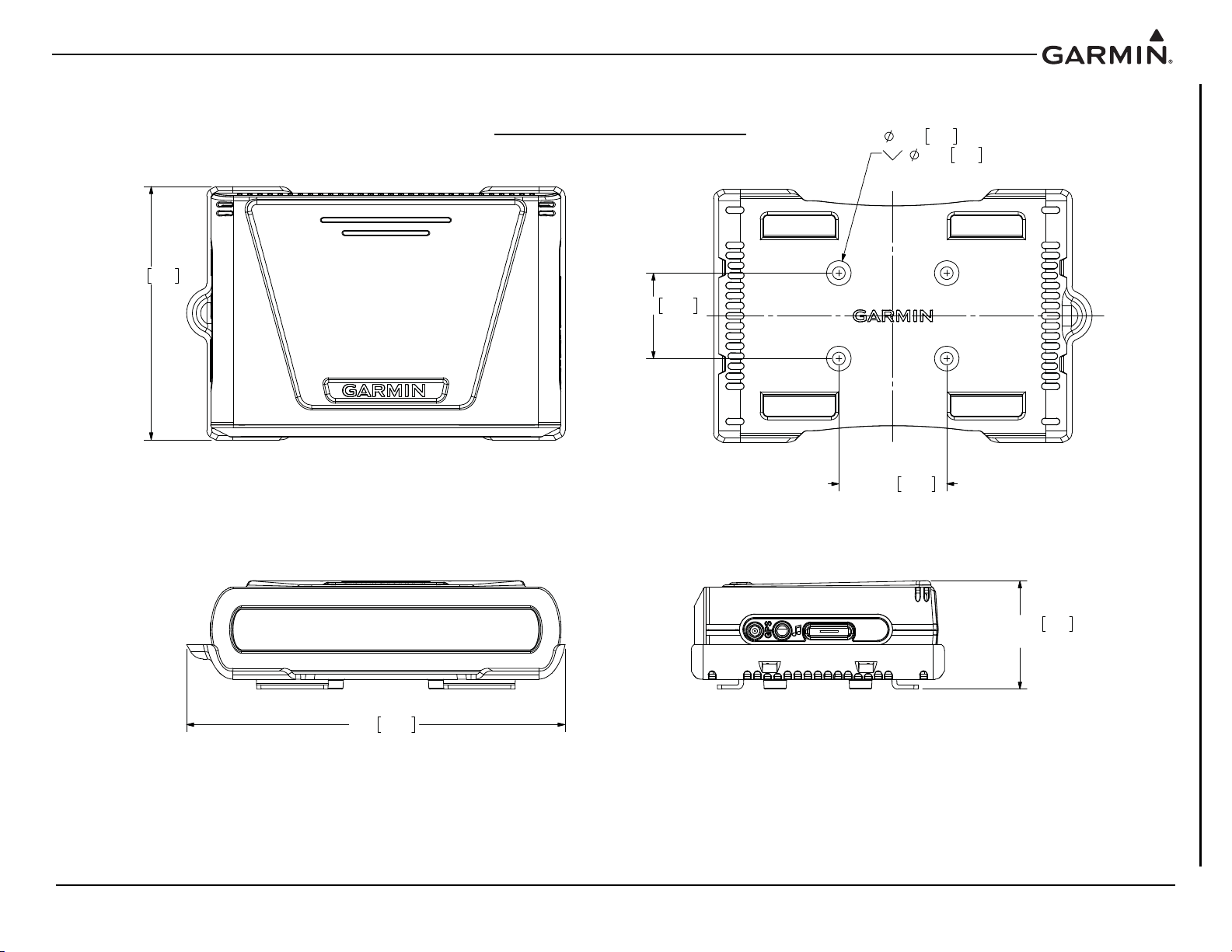
NOTES:
DIMENSIONS: INCHES[mm]. METRIC VALUES ARE FOR REFERENCE ONLY.1.
DIMENSIONS ARE NOMINAL AND TOLERANCES ARE NOT IMPLIED UNLESS SPECIFICALLY STATED.2.
MOUNTING HOLES ARE FOR #8 100° FLAT HEAD SCREWS.3.
WITH MOUNTING BRACKET
(SHOWN WITH GDL 51)
GDL 51=1.51
38.3
GDL 50/52=1.71[43.4]
3.52 89.5
2X 1.500
38.10
2X 1.188
30.16
.177
4.50 THRU ALL
.344
8.74 X 100°
NOTE 3
5.26
133.6
Figure A-4 GDL 51 with Mounting Bracket Outline and Installation Drawing
190-02087-10 GDL 50(R)/51(R)/52(R) Installation Manual
Rev. 2 Page A-4

WITH MOUNTING BRACKET & NON-SLIP PAD ACCESSOSRY
(SHOWN WITH GDL 51)
GDL 51=1.65 41.9
GDL 50/52=1.85[47.0]
5.50 139.7
7.50
190.5
APPENDIX A OUTLINE AND INSTALLATION DRAWINGS
Figure A-5 GDL 51 with Mounting Bracket and Pad Outline and Installation Drawing
190-02087-10 GDL 50(R)/51(R)/52(R) Installation Manual
Rev. 2 Page A-5

APPENDIX A OUTLINE AND INSTALLATION DRAWINGS
GDL 50R=2.76[70.1]
GDL 51R=2.80[71.1]
GDL 52R=2.85
72.4
C.O.G.
NOTE 3
3X 2.215
56.26
GDL 51R=3.20[81.3]
GDL 52R=3.08 78.2
GDL 50R=2.90[73.7]
C.O.G. NOTE 3
.88 22.4
C.O.G.
NOTE 3
GDL 51R
CONNECTOR SHOWN BROKEN
OUT TO REVEAL MOUNTING HOLE
2X 2.250 57.15
3X 4.430 112.5
21.04
.828
7.24.285
2X 4.500 114.30
6X .156
3.96
NOTE 4
MOUNTING HOLES FOR #6 100° FLAT HEAD SCREWS.
3.
4.
NOTES:
DIMENSIONS: INCHES[mm]. METRIC VALUES ARE FOR REFERENCE ONLY.1.
DIMENSIONS ARE NOMINAL AND TOLERANCES ARE NOT IMPLIED UNLESS SPECIFICALLY STATED.2.
CENTER OF GRAVITY (C.O.G.) LOCATION SHOWN IS WITHOUT CONNECTOR KIT INSTALLED.
GDL 5XR UNITS
(GDL 52R SHOWN)
1.63
41.4
6.16 156.4
GDL 50R
6.46 164.2
127.0
5.00
.12 3.0
GDL 52R
190-02087-10 GDL 50(R)/51(R)/52(R) Installation Manual
Rev. 2 Page A-6
Figure A-6 GDL 5XR Outline and Installation Drawing

APPENDIX A OUTLINE AND INSTALLATION DRAWINGS
GDL 50R 011-03910-10
GDL 51R 011-03910-50
GDL 52R (SHOWN) 011-03910-30
INCLUDED IN
010-12498-60
CONNECTOR KIT
15 PIN D-SUB CONNECTOR
330-00625-15
BACKSHELL ASSEMBLY
011-01855-01
Figure A-7 GDL 5XR Installation Drawing
190-02087-10 GDL 50(R)/51(R)/52(R) Installation Manual
Rev. 2 Page A-7

APPENDIX B INTERCONNECT DRAWINGS
Figure B-1 GDL 5X - aera 660/79X
190-02087-10 GDL 50(R)/51(R)/52(R) Installation Manual
Rev. 2 Page B-1

Figure B-2 GDL 5XR - aera 660/79X, GMA 24X(R)
190-02087-10 GDL 50(R)/51(R)/52(R) Installation Manual
Rev. 2 Page B-2

Figure B-3 GDL 5XR - GMA 24X(R), GDU 4XX
190-02087-10 GDL 50(R)/51(R)/52(R) Installation Manual
Rev. 2 Page B-3
 Loading...