

Page 1
G5 Electronic Flight Instrument
Pilot's Guide
for Non-Certified Aircraft
Page 2

Blank Page
Page 3

SYSTEM OVERVIEW
FLIGHT INSTRUMENTS
AFCS
ADDITIONAL FEATURES
INDEX
Page 4

Blank Page
Page 5

© 2017 Garmin Ltd. or its subsidiaries. All rights reserved.
This manual reflects the operation of System Software version 4.10 or later. Some differences
in operation may be observed when comparing the information in this manual to earlier or later
software versions.
Garmin International, Inc., 1200 East 151st Street, Olathe, Kansas 66062, U.S.A.
Garmin AT, Inc.,2345 Turner Road SE, Salem, OR 97302, U.S.A.
Garmin (Europe) Ltd., Liberty House, Hounsdown Business Park, Southampton, Hampshire
SO40 9LR U.K.
Garmin Corporation, No. 68, Zhangshu 2nd Road, Xizhi District, New Taipei City, Taiwan
Web Site Address: www.garmin.com
Except as expressly provided herein, no part of this manual may be reproduced, copied,
transmitted, disseminated, downloaded or stored in any storage medium, for any purpose without
the express written permission of Garmin. Garmin hereby grants permission to download a
single copy of this manual and of any revision to this manual onto a hard drive or other electronic
storage medium to be viewed for personal use, provided that such electronic or printed copy
of this manual or revision must contain the complete text of this copyright notice and provided
further that any unauthorized commercial distribution of this manual or any revision hereto is
strictly prohibited.
Garmin® is a registered trademark of Garmin Ltd. or its subsidiaries. This trademark may not be
used without the express permission of Garmin.
October, 2017 190-02072-00 Rev. G Printed in the U.S.A.
Page 6

Warnings, Cautions & Notes
BATTERY WARNINGS:
If these guidelines are not followed, the lithium-ion battery may experience
a shortened life span or may present a risk of damage to the device, fire,
chemical burn, electrolyte leak, and/or injury.
•
Do not leave the battery exposed to a heat source or in a high
temperature environment. To help prevent damage, store the battery
out of direct sunlight.
•
For maximum battery longevity, store within a temperature range of
-4˚F to 68˚F (from -20˚C to 20˚C).
•
Do not use a sharp object to remove the battery.
•
Do not disassemble, puncture, damage, or incinerate the device or
battery.
•
Keep the battery away from children.
•
Only replace the battery with the approved replacement from Garmin.
Using another battery presents a risk of fire or explosion. To purchase
a replacement battery, see you Garmin dealer or the Garmin website.
•
Contact your local waste disposal department to dispose of the device
and battery in accordance with applicable local laws and regulations.
WARNING: To reduce the risk of unsafe operation, carefully review and
understand all aspects of the G5 Install Manual & Pilot's Guide documentation
and the Pilot’s Operating Handbook of the aircraft. Thoroughly practice basic
operation prior to actual use. During flight operations, carefully compare
indications from the G5 to all available flight displays. For safety purposes,
always resolve any discrepancies.
WARNING: The altitude calculated by the G5 internal GPS receiver is geometric height above Mean Sea Level and could vary significantly from the
altitude displayed by pressure altimeters. Always use the pressure altitude
display, when available, for determining or selecting aircraft altitude.
WARNING: The United States government operates the Global Positioning
System and is solely responsible for its accuracy and maintenance. The GPS
system is subject to changes which could affect the accuracy and performance
of all GPS equipment.
G5 Electronic Flight Instrument Pilot's Guide for Non-Certified Aircraft
190-02072-00 Rev. G
Page 7
Warnings, Cautions & Notes
WARNING: For safety reasons, the G5 operational procedures must be learned
on the ground.
WARNING: This product, its packaging, and its components contain chemicals
known to the State of California to cause cancer, birth defects, or reproductive
harm. This Notice is being provided in accordance with California Proposition
65. If you have any questions or would like additional information, please
refer to our website at www.garmin.com/prop65
CAUTION: The display uses a lens with a special coating that may be sensitive
to certain oils, waxes, and abrasive cleaners. CLEANERS CONTAINING
AMMONIA WILL HARM THE ANTI-REFLECTIVE COATING. It is very important
to clean the lens using a clean, lint-free cloth and a cleaner that is specified
as safe for anti-reflective coatings. Avoid any chemical cleaners or solvents
that can damage plastic components.
CAUTION: The G5 does not contain any user-serviceable parts. Repairs should
only be made by an authorized Garmin service center. Unauthorized repairs
or modifications could result in permanent damage to the equipment and
void both the warranty and the authority to operate this device under FAA,
FCC, and other applicable regulations.
NOTE: The G5 may only be installed in type-certificated aircraft in accordance
with Garmin STC SA01818WI.
NOTE: The term LRU, as used throughout this manual is an abbreviation for
Line Replaceable Unit. LRU is used generically in aviation for a product (such
as a GSA 28 or GMC 307) that can be readily "swapped out" (usually as a
single component) for troubleshooting/repair.
190-02072-00 Rev. G
G5 Electronic Flight Instrument Pilot's Guide for Non-Certified Aircraft
Page 8

Warnings, Cautions & Notes
NOTE: The G5 has a very high degree of functional integrity. However, the
pilot must recognize that providing monitoring and/or self-test capability for
all conceivable system failures is not practical. Although unlikely, it may be
possible for erroneous operation to occur without a fault indication shown by
the G5. It is thus the responsibility of the pilot to detect such an occurrence
by means of cross-checking with all redundant or correlated information
available in the cockpit.
NOTE: All visual depictions contained within this document, including screen
images of the G5 display, are subject to change and may not reflect the most
current G5 functionality.
NOTE: Use of polarized eyewear may cause the display to appear dim or
blank.
G5 Electronic Flight Instrument Pilot's Guide for Non-Certified Aircraft
190-02072-00 Rev. G
Page 9

Warnings, Cautions & Notes
DECLARATION OF CONFORMITY
Hereby, Garmin declares that this product is in compliance with the Directive 2014/53/EU. The full
text of the EU declaration of conformity is available at the following internet address www.garmin.
com/compliance.
FCC
This device complies with Part 15 of the FCC Rules. Operation is subject to the following two
conditions: (1) this device may not cause harmful interference, and (2) this device must accept
any interference received, including interference that may cause undesired operation.
This equipment has been tested and found to comply with the limits for a Class B digital
device pursuant to part 15 of the FCC Rules. These limits are designed to provide reasonable
protection against harmful interference in a residential installation. This equipment generates,
uses, and can radiate radio frequency energy and if not installed and used in accordance with
the instructions, may cause harmful interference to radio communications. However, there is
no guarantee that interference will not occur in a particular installation. If this equipment
does cause harmful interference to radio or television reception, which can be determined by
turning the equipment off and on, the user is encouraged to try to correct the interference by
one of the following measures:
• Reorient or relocate the receiving antenna.
• Increase the separation between the equipment and receiver.
• Connect the equipment into an outlet on a circuit different from that to which the
receiver is connected.
• Consult the dealer or an experienced radio/TV technician for help.
LICENSE AGREEMENT AND WARRANTY
ContaCt Garmin
Contact Garmin if you have any questions while using the G5 at www.flygarmin.com.
Software LiCenSe aGreement
BY USING THE DEVICE, COMPONENT OR SYSTEM MANUFACTURED OR SOLD BY GARMIN
(“THE GARMIN PRODUCT”), YOU AGREE TO BE BOUND BY THE TERMS AND CONDITIONS
OF THE FOLLOWING SOFTWARE LICENSE AGREEMENT. PLEASE READ THIS AGREEMENT
CAREFULLY. Garmin Ltd. and its subsidiaries (“Garmin”) grants you a limited license to use
the software embedded in the Garmin Product (the “Software”) in binary executable form in
the normal operation of the Garmin Product. Title, ownership rights, and intellectual property
190-02072-00 Rev. G
G5 Electronic Flight Instrument Pilot's Guide for Non-Certified Aircraft
Page 10

Warnings, Cautions & Notes
rights in and to the Software remain with Garmin and/or its third-party providers. You
acknowledge that the Software is the property of Garmin and/or its third-party providers and
is protected under the United States of America copyright laws and international copyright
treaties. You further acknowledge that the structure, organization, and code of the Software
are valuable trade secrets of Garmin and/or its third-party providers and that the Software in
source code form remains a valuable trade secret of Garmin and/or its third-party providers.
You agree not to reproduce, decompile, disassemble, modify, reverse assemble, reverse
engineer, or reduce to human readable form the Software or any part thereof or create any
derivative works based on the Software. You agree not to export or re-export the Software
to any country in violation of the export control laws of the United States of America.
aviation Limited warranty
All Garmin avionics products are warranted to be free from defects in materials or
workmanship for the earlier of: 2 years or 800 flight hours from the date of purchase for
new TSO remote-mount and TSO panel-mount products; 1 year or 400 flight hours from the
date of purchase for new Non-TSO remote-mount* and Non-TSO panel-mount*, portable
products and any purchased newly-overhauled products; 6 months or 200 flight hours for
factory repaired or newly-overhauled products exchanged through a Garmin Authorized
Service Center. Within the applicable period, Garmin will, at its sole option, repair or replace
any components that fail in normal use. Such repairs or replacement will be made at no
charge to the customer for parts or labor, provided that the customer shall be responsible for
any transportation cost. This Limited Warranty does not apply to: (i) cosmetic damage, such
as scratches, nicks and dents; (ii) consumable parts, such as batteries, unless product damage
has occurred due to a defect in materials or workmanship; (iii) damage caused by accident,
abuse, misuse, water, flood, fire, or other acts of nature or external causes; (iv) damage
caused by service performed by anyone who is not an authorized service provider of Garmin;
or (v) damage to a product that has been modified or altered without the written permission
of Garmin. In addition, Garmin reserves the right to refuse warranty claims against products
or services that are obtained and/or used in contravention of the laws of any country.
This Limited Warranty also does not apply to, and Garmin is not responsible for, any
degradation in the performance of any Garmin navigation product resulting from its use
in proximity to any handset or other device that utilizes a terrestrial broadband network
operating on frequencies that are close to the frequencies used by any Global Navigation
Satellite System (GNSS) such as the Global Positioning Service (GPS). Use of such devices
may impair reception of GNSS signals.
G5 Electronic Flight Instrument Pilot's Guide for Non-Certified Aircraft
190-02072-00 Rev. G
Page 11

Warnings, Cautions & Notes
THE WARRANTIES AND REMEDIES CONTAINED HEREIN ARE EXCLUSIVE AND IN LIEU OF
ALL OTHER WARRANTIES, WHETHER EXPRESS, IMPLIED OR STATUTORY, INCLUDING ANY
LIABILITY ARISING UNDER ANY WARRANTY OF MERCHANTABILITY OR FITNESS FOR A
PARTICULAR PURPOSE, STATUTORY OR OTHERWISE. THIS WARRANTY GIVES YOU SPECIFIC
LEGAL RIGHTS, WHICH MAY VARY FROM STATE TO STATE.
IN NO EVENT SHALL GARMIN BE LIABLE FOR ANY INCIDENTAL, SPECIAL, INDIRECT OR
CONSEQUENTIAL DAMAGES, WHETHER RESULTING FROM THE USE, MISUSE OR INABILITY
TO USE THE PRODUCT OR FROM DEFECTS IN THE PRODUCT. SOME STATES DO NOT
ALLOW THE EXCLUSION OF INCIDENTAL OR CONSEQUENTIAL DAMAGES, SO THE ABOVE
LIMITATIONS MAY NOT APPLY TO YOU.
Garmin retains the exclusive right to repair or replace (with a new or newly-overhauled
replacement product) the product or software or offer a full refund of the purchase price at
its sole discretion. SUCH REMEDY SHALL BE YOUR SOLE AND EXCLUSIVE REMEDY FOR ANY
BREACH OF WARRANTY.
Online Auction Purchases: Products purchased through online auctions are not eligible for
warranty coverage. Online auction confirmations are not accepted for warranty verification.
To obtain warranty service, an original or copy of the sales receipt from the original retailer is
required. Garmin will not replace missing components from any package purchased through
an online auction.
International Purchases: A separate warranty may be provided by international
distributors for devices purchased outside the U.S. depending on the country. If applicable,
this warranty is provided by the local in-country distributor and this distributor provides
local service for your device. Distributor warranties are only valid in the area of intended
distribution. Devices purchased in the U.S. or Canada must be returned to the Garmin service
center in the U.K., the U.S., Canada, or Taiwan for service.
*All new G3X units, including Non-TSO remote-mount or Non-TSO panel-mount, are
warranted to be free from defects in materials or workmanship for the earlier of: 2 years or
800 flight hours from the date of purchase.
190-02072-00 Rev. G
G5 Electronic Flight Instrument Pilot's Guide for Non-Certified Aircraft
Page 12
Part Number Change Summary
190-02072-00 Initial release.
Rev Date Description
A April, 2016 Production Release.
B April, 2016 Updates to Installation Manual section.
C September, 2016 Added interconnect drawings, various updates
D December, 2016 Added autopilot trim and speed annunciations.
E May, 2017 Added GMU 11 info, various updates
F June, 2017 Added Declaration of Conformity for RED compliance
G October, 2017 Removed Installation Manual section
Updated AFCS Status Display throughout
Added Electronic Stability & Protection (ESP)
Added support for multiple navigation sources
Added 'Unable to Charge Battery' indication
Added ability to configure Sky Pointer or Ground Pointer
Other miscellaneous updates for Software Version 4.10
G5 Electronic Flight Instrument Pilot's Guide for Non-Certified Aircraft
190-02072-00 Rev. G
Page 13

Table of Contents
Section 1 System Overview .................................................................................................. 5
1.1 Bezel Overview .................................................................................................................. 5
1.2 micro-SD™ Cards .................................................................................................................. 6
1.3 System Power-up ..............................................................................................................6
1.4 Operation ............................................................................................................................ 7
1.4.1 G5 Annunciations .......................................................................................................7
1.4.2 G5 Attitude ................................................................................................................ 7
1.4.3 G5 Heading ............................................................................................................... 8
1.4.4 Backlight Intensity ...................................................................................................... 8
1.5 Accessing Functionality ................................................................................................... 9
1.5.1 Pages ......................................................................................................................... 9
1.5.2 Menu ....................................................................................................................... 10
Section 2 Flight Instruments .............................................................................................. 11
2.1 PFD Page ........................................................................................................................... 11
2.1.1 Airspeed Indicator .................................................................................................... 12
2.1.2 Attitude Indicator ..................................................................................................... 15
2.1.3 Altimeter .................................................................................................................. 17
2.1.4 Turn Rate Indicator ................................................................................................... 19
2.1.5 Heading/Ground Track (PFD Page)............................................................................. 19
2.1.6 Vertical Speed Indicator (VSI) .................................................................................... 21
2.1.7 PFD Pitch Attitude Offset .......................................................................................... 22
2.1.8 Battery Status Indicator ............................................................................................ 23
2.2 HSI Page ............................................................................................................................ 24
2.2.1 Horizontal Situation Indicator (HSI) ........................................................................... 25
2.2.2 Heading/Ground Track (HSI Page) ............................................................................. 28
2.3 Navigation ........................................................................................................................ 29
2.3.1 Course Deviation Indicator (CDI) ............................................................................... 30
2.3.2 Vertical Deviation Indicator and VNAV Indicator ........................................................ 32
2.3.3 Course Selection ...................................................................................................... 36
Section 3 Automatic Flight Control System (Optional) .......................................37
3.1 AFCS System Architecture ............................................................................................. 37
3.1.1 Autopilot and Yaw Damper Operation ....................................................................... 37
3.1.2 Flight Control ........................................................................................................... 38
3.1.3 Pitch Axis and Trim ................................................................................................... 38
3.1.4 Roll Axis ...................................................................................................................38
3.1.5 Yaw Axis .................................................................................................................. 38
3.1.6 Control Wheel Steering (CWS) (Optional) .................................................................. 39
3.1.7 G5 AFCS Status Box ................................................................................................. 39
3.1.8 G5 AFCS Configuration............................................................................................. 40
3.1.9 AFCS Operation ........................................................................................................ 40
3.1.10 AFCS PRE-FLIGHT Actions (Standalone Installation) ................................................. 41
190-02072-00 Rev. G i
G5 Electronic Flight Instrument Pilot's Guide for Non-Certified Aircraft
Page 14

Table of Contents
3.1.11 AFCS Controls ........................................................................................................ 42
3.1.12 Flight Director Operation ........................................................................................ 47
3.1.13 Vertical Modes ....................................................................................................... 52
3.1.14 Lateral Modes ........................................................................................................ 63
3.2 System Messages ............................................................................................................ 71
3.3 AFCS Alerts (Optional) .................................................................................................... 72
3.3.1 Status Alerts .............................................................................................................72
3.3.2 Speed Alerts ............................................................................................................. 72
Section 4 Additional Features ........................................................................................... 73
4.1 Electronic Stability & Protection (ESP) ....................................................................... 73
4.1.1 Roll Engagement ...................................................................................................... 75
4.1.2 Pitch Engagement .................................................................................................... 76
4.1.3 Airspeed Protection .................................................................................................. 78
Index ...................................................................................................................................Index-1
ii
G5 Electronic Flight Instrument Pilot's Guide for Non-Certified Aircraft
190-02072-00 Rev. G
Page 15

Table of Contents
190-02072-00 Rev. G iii
G5 Electronic Flight Instrument Pilot's Guide for Non-Certified Aircraft
Page 16

Table of Contents
Blank Page
iv
G5 Electronic Flight Instrument Pilot's Guide for Non-Certified Aircraft
190-02072-00 Rev. G
Page 17
System Overview
SECTION 1 SYSTEM OVERVIEW
System Overview Flight Instruments AFCS Additional Features Index
The G5 is an electronic instrument display capable of operating as a standalone
flight display or a fully integrated backup instrument for G3X systems. It features a
bright, sunlight readable, 3.5-inch color display which is sized to fit in a standard
3-1/8-inch instrument cutout.
When installed as part of a G3X system, the G5 provides a redundant source of
attitude and air data to the G3X displays, and additionally provides backup autopilot
control allowing coupled GPS approaches to be flown or continued in the event of
primary flight display is unavailability. The G5 additionally provides backup autopilot
control allowing coupled GPS approaches to be flown or continued in the event of
primary flight display loss. In the case of aircraft power loss, the optional battery
backup sustains the G5 flight display with up to 4 hours of emergency power.
1.1 BEZEL OVERVIEW
Power/
Backlight
Figure 1-1 G5 Bezel Overview
190-02072-00 Rev. G 5
G5 Electronic Flight Instrument Pilot's Guide for Non-Certified Aircraft
Light
Sensor
microSD™
Card Slot
KnobAmbient
Page 18

System Overview
System OverviewFlight InstrumentsAFCSAdditional FeaturesIndex
Power
Button
microSD™
Card Slot
Press
Knob
Press to turn unit ON. Press and hold for 5 seconds to
turn unit OFF. Once on, press to adjust the backlight.
Insert microSD card to update software and log data.
Press to access the Menu.
From the Menu, press to select the desired menu item.
Press to accept the displayed value when editing numeric
data or selecting from a list.
From the Main Menu, turn the Knob to move the cursor
to the desired menu item.
From the PFD Page, rotate to adjust the barometric
setting.
Turn
From the HSI Page, rotate to adjust the heading or track
bug.
Turn to select the desired value when editing numeric
data or selecting from a list.
1.2 micro-SD™ CARDS
The G5 data card slot uses micro Secure Digital (SD) cards. The microSD™ card can
be used for software updates and data logging. The maximum supported card size is
32GB.
Installing an microSD™ Card:
1)
Insert the microSD™ card in the microSD™ card slot with the card contacts
facing down (the card should be flush with the face of the bezel).
2)
To eject the card, gently press on the microSD™ card to release the spring
latch.
1.3 SYSTEM POWER-UP
During system initialization, the G5 displays the message ‘ALIGNING’ over the
attitude indicator. The G5 should display valid attitude typically within the first minute
of power-up. The G5 can align itself both while taxiing and during level flight.
6
G5 Electronic Flight Instrument Pilot's Guide for Non-Certified Aircraft
190-02072-00 Rev. G
Page 19
System Overview
1.4 OPERATION
NOTE: Refer to the Installation portion of this manual for information on
configuring the G5.
System Overview Flight Instruments AFCS Additional Features Index
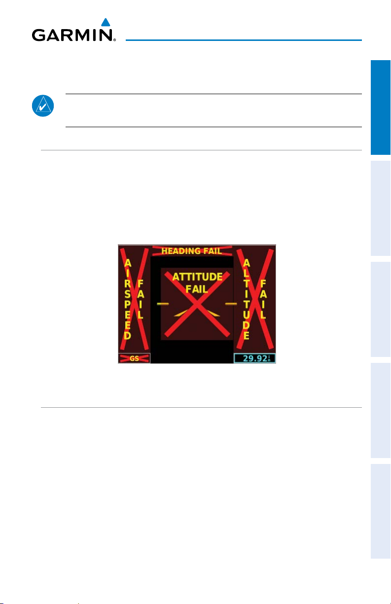
1.4.1 G5 ANNUNCIATIONS
When a G5 function fails, a Red-X is typically displayed over the instrument(s) or
data experiencing the failure. Upon G5 power-up, certain instruments remain invalid
as equipment begins to initialize. All instruments should be operational within
one minute of power-up. If any instrument remains flagged, and it is not likely an
installation related problem, the G5 should be serviced by a Garmin-authorized repair
facility .
Figure 1-2 G5 Failure Annunciations
1.4.2 G5 ATTITUDE
The G5 calculates aircraft attitude using information from its built-in inertial sensors.
Any failure of the inertial sensors results in loss of attitude and information (indicated
by Red-X flags over the PFD attitude display). If the G5 senses that the attitude solution
is valid, but not yet within the internal accuracy limits, "ALIGNING" is displayed. The
G5 can align itself both while taxiing and during level flight.
The G5 will also use GPS and airspeed data to provide the most accurate attitude
information. If none of these additional sources of information are available, attitude
calculations will still be valid but accuracy may be slightly affected.
190-02072-00 Rev. G 7
G5 Electronic Flight Instrument Pilot's Guide for Non-Certified Aircraft
Page 20

System Overview
1.4.3 G5 HEADING
Magnetic heading is available in a standalone installation with a magnetometer,
and when the G5 is configured as a backup in a G3X/G3X Touch system and the G5
is receiving magnetic heading data from an ADAHRS unit. If magnetic heading input
data is not available, the G5 will display GPS-derived ground track instead.
System OverviewFlight InstrumentsAFCSAdditional FeaturesIndex
The G5 corrects for shifts and variations in the Earth’s magnetic field by applying the
Magnetic Field Variation Database. The Magnetic Field Variation Database is derived
from the International Geomagnetic Reference Field (IGRF). The IGRF is a mathematical
model that describes the Earth’s main magnetic field and its annual rate of change.
The database is updated approximately every 5 years via a software update. Failure to
update this database could lead to erroneous heading information being displayed to
the pilot.
If the G5 senses that the magnetic heading measurement is valid, but possibly
outside of the internal accuracy limits, the numeric heading is displayed in yellow.
1.4.4 BACKLIGHT INTENSITY
When set to Auto, the backlight is automatically adjusted according to ambient
light conditions. When set to Manual, the backlight level is set by the pilot.
Adjusting backlight intensity:
1)
While the unit is turned on, press the Power Button.
2)
Turn the Knob to adjust the backlight intensity.
3)
Press the Knob to close the backlight page.
Setting the backlight intensity to automatic:
1)
While the unit is turned on, press the Power Button.
2)
Press the Power Button again to select Auto.
3)
Press the Knob to close the backlight page.
8
G5 Electronic Flight Instrument Pilot's Guide for Non-Certified Aircraft
190-02072-00 Rev. G
Page 21
System Overview
1.5 ACCESSING FUNCTIONALITY
1.5.1 PAGES
NOTE: The G5 will automatically return to the PFD Page when the aircraft
enters an unusual attitude (if enabled in the system configuration). Refer to
the Installation Manual section for more information.
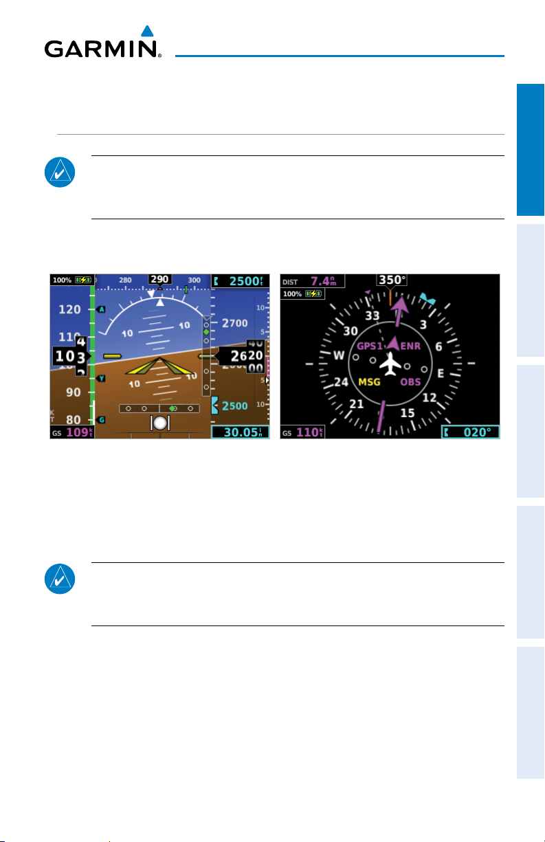
The G5 has two main pages, the HSI Page and the PFD Page. The HSI Page can be
accessed from the PFD Page (unless it has been disabled in configuration).
Figure 1-3 PFD Page Figure 1-4 HSI Page
System Overview Flight Instruments AFCS Additional Features Index
Displaying the HSI page from the PFD page:
1)
From the PFD Page press the Knob to display the Menu.
2)
Use the Knob to select HSI.
NOTE: The G5 can be configured to power-up on either the PFD or HSI page
(if allowed by the current system configuration). Refer to the Installation
Manual section for more information.
190-02072-00 Rev. G 9
G5 Electronic Flight Instrument Pilot's Guide for Non-Certified Aircraft
Page 22
System Overview
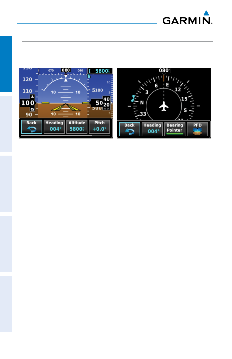
1.5.2 MENU
Press the Knob to access the G5 Menu. Navigate the menu by rotating the Knob
and make selections by pressing the Knob.
System OverviewFlight InstrumentsAFCSAdditional FeaturesIndex
Figure 1-5 PFD Page Menu Figure 1-6 HSI Page Menu
10
G5 Electronic Flight Instrument Pilot's Guide for Non-Certified Aircraft
190-02072-00 Rev. G
Page 23
Flight Instruments
SECTION 2 FLIGHT INSTRUMENTS
System Overview Flight Instruments AFCS Additional Features Index
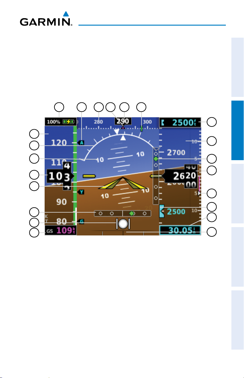
2.1 PFD PAGE
The G5 PFD Page displays a horizon, airspeed, attitude, altitude, vertical speed,
heading, and course deviation information. The following flight instruments and
supplemental flight data are displayed on the PFD Page.
18 172021 1922
16
1
2
3
4
5
6
7
8
15
14
13
12
11
10
9
Figure 2-1 G5 PFD Flight Instruments
190-02072-00 Rev. G 11
G5 Electronic Flight Instrument Pilot's Guide for Non-Certified Aircraft
Page 24
Flight Instruments
1
Airspeed Indicator
2
Attitude Indicator
3
Pitch Scale
4
Current Airspeed
5
System OverviewFlight InstrumentsAFCSAdditional FeaturesIndex
Aircraft Symbol
6
Course Deviation Indicator
7
Slip/Skid Indicator
8
Ground Speed (GS)
9
Turn Rate Indicator
Altimeter Barometric Setting
10
Selected Altitude Bug
11
2.1.1 AIRSPEED INDICATOR
NOTE: The G5 Vspeed Reference values depend upon the aircraft’s specific
system configuration and may vary from the examples discussed in this section.
Vertical Speed Indicator
12
Current Altitude
13
VNAV Indicator or Vertical
14
Deviation Indicator
Altimeter
15
Selected Altitude
16
Navigation Course
17
Current Heading or Ground Track
18
Ground Track
19
Heading or Ground Track
20
Vspeed Reference
21
Battery Status Indicator
22
The Airspeed Indicator displays airspeed on a rolling number gauge using a moving
tape. The numeric labels and major tick marks on the moving tape are marked at
intervals of 10 knots. Speed indication starts at 30 knots, with 60 knots of airspeed
viewable at any time. The actual airspeed is displayed inside the black pointer. The
pointer remains black until reaching never-exceed speed (VNE), at which point it turns
red.
A color-coded (red, white, green, yellow, and red/white “barber pole”) speed range
strip is located on the moving tape. The colors denote flaps operating range, normal
operating range, caution range, and never-exceed speed (VNE). A red range is also
present for low speed awareness.
12
G5 Electronic Flight Instrument Pilot's Guide for Non-Certified Aircraft
190-02072-00 Rev. G
Page 25
Flight Instruments
The Airspeed Trend Vector is a vertical, magenta line, extending up or down on the
airspeed scale, shown to the right of the color-coded speed range strip. The end of
System Overview Flight Instruments AFCS Additional Features Index
the trend vector corresponds to the predicted airspeed in 6 seconds if the current rate
of acceleration is maintained. If the trend vector crosses VNE, the text of the actual
airspeed readout changes to yellow. The trend vector is absent if the speed remains
constant or if any data needed to calculate airspeed is not available due to a system
failure.
Airspeed Color Ranges
Actual Airspeed
Ground Speed
Figure 2-2 Airspeed Indicator
Airspeed Trend Vector
Vspeed References
2.1.1.1 VNE ADJUSTED FOR TRUE AIRSPEED OR MACH
NUMBER (OPTIONAL)
NOTE: Mach number data is only available when the G5 is installed as part
of a G3X/G3X Touch system and is receiving air temperature data from an
ADAHRS.
The airspeed indicator can optionally be configured to display VNE adjusted for true
airspeed or maximum Mach number (MMO). This is useful in aircraft where true
airspeed or Mach number must be kept below a certain limit. If configured, the G5
can display VNE based on TAS or Mach in addition to IAS, which will cause the displayed
value for VNE to be reduced at high altitudes. A solid red band is used between the TAS
or Mach limit and the actual indicated value for VNE.
190-02072-00 Rev. G 13
G5 Electronic Flight Instrument Pilot's Guide for Non-Certified Aircraft
Page 26
Flight Instruments
2.1.1.2 VSPEED REFERENCE
Vspeed references including VNE, Vno, Vso, Vs1, Vfe, Va, Vx, Vy, V
, Vg, Vr, can be configured
Yse
to display on the G5, refer to the Installation Manual section for more information.
When airspeed is present, the Vspeeds configured are displayed at their respective
locations to the right of the airspeed scale, otherwise the Vspeeds are displayed at the
System OverviewFlight InstrumentsAFCSAdditional FeaturesIndex
bottom of the airspeed indicator.
Vspeed References
Figure 2-3 Vspeed References
14
G5 Electronic Flight Instrument Pilot's Guide for Non-Certified Aircraft
190-02072-00 Rev. G
Page 27
Flight Instruments
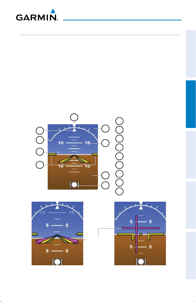
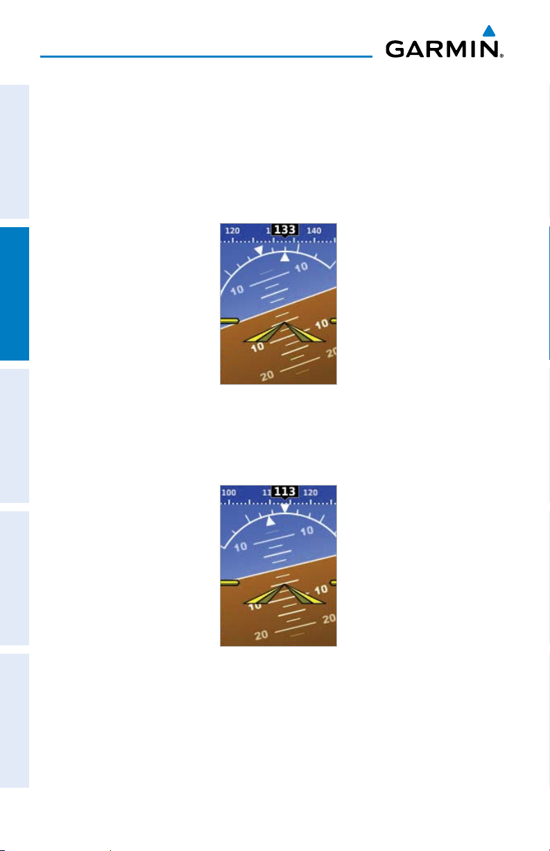
2.1.2 ATTITUDE INDICATOR
System Overview Flight Instruments AFCS Additional Features Index
Attitude information is displayed over a virtual blue sky and brown ground with a
white horizon line. The Attitude Indicator displays the pitch (indicated by the yellow
symbolic aircraft on the pitch scale), roll, and slip/skid information.
The horizon line is part of the pitch scale. Pitch markings occur at 2.5˚ intervals
through all pitch ranges. Refer to the Installation Manual section to configure the
pitch scale.
The inverted white triangle indicates zero on the roll scale. Major tick marks at 30˚
and 60˚ and minor tick marks at 10˚, 20˚, and 45˚ are shown to the left and right of the
zero. Angle of bank is indicated by the position of the pointer on the roll scale.
Slip/skid is indicated by the location of the ball.
9
1
2
3
4
Figure 2-4 Attitude Indicator
1
Roll Pointer
8
2
Roll Scale
3
7
6
5
Horizon Line
4
Aircraft Symbol
5
Slip/Skid Indicator
6
Land Representation
7
Pitch Scale
8
Sky Representation
9
Roll Scale Zero
Flight Director
Figure 2-5 Attitude Indicator with
Flight Director (Single Cue)
190-02072-00 Rev. G 15
G5 Electronic Flight Instrument Pilot's Guide for Non-Certified Aircraft
Figure 2-6 Attitude Indicator with
Flight Director (Dual Cue)
Page 28
Flight Instruments
2.1.2.1 ATTITUDE CONFIGURATION
The roll (bank angle) indication may be configured to be a Ground Pointer (default)
or a Sky Pointer. Refer to the G5 Installation Manual for configuration information.
The Ground Pointer configuration displays both the roll arc and the pitch ladder
anchored to the horizon and the roll pointer beneath the roll arc pointing to the
System OverviewFlight InstrumentsAFCSAdditional FeaturesIndex
present roll angle.
Figure 2-7 Ground Pointer Configuration
The Sky Pointer configuration displays the pitch ladder moving with the horizon, but
the roll arc remains fixed and centered in the display. The roll pointer beneath the roll
arc moves with the horizon and in the opposite direction of aircraft roll.
Figure 2-8 Sky Pointer Configuration
16
G5 Electronic Flight Instrument Pilot's Guide for Non-Certified Aircraft
190-02072-00 Rev. G
Page 29
Flight Instruments
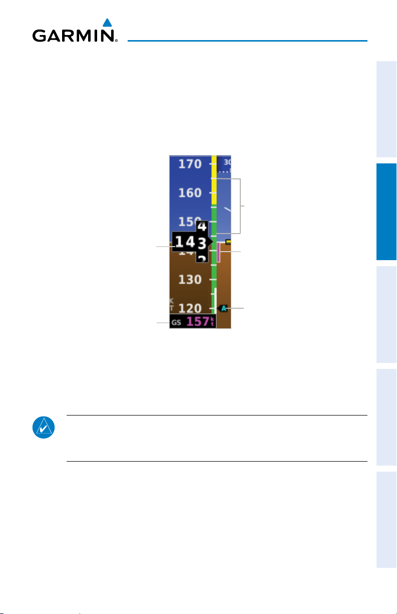
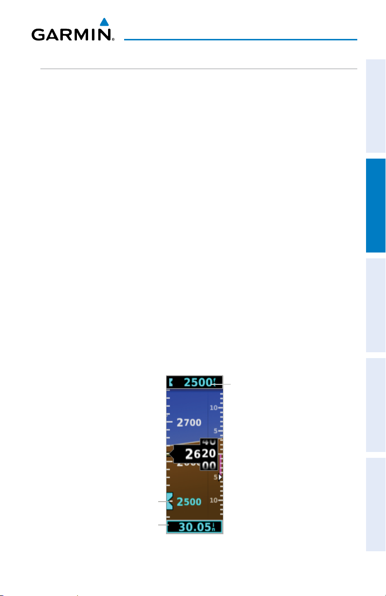
2.1.3 ALTIMETER
System Overview Flight Instruments AFCS Additional Features Index
The Altimeter displays 400 feet of barometric altitude values at a time on a rolling
number gauge using a moving tape. Numeric labels and major tick marks are shown
at intervals of 100 feet. Minor tick marks are at intervals of 20 feet. The current
altitude is displayed in the black pointer.
The Selected Altitude is displayed above the Altimeter in the box indicated by a
selection bug symbol. A bug corresponding to this altitude is shown on the tape; if
the Selected Altitude exceeds the range shown on the tape, the bug appears at the
corresponding edge of the tape.
The Selected Altitude is synchronized between the G5 and the other displays in a
G3X/G3X Touch system.
Setting the selected altitude:
Rotate the ALT SEL Knob on the GMC 307.
Or
1)
Press the Knob to display the Menu.
2)
Select Altitude and use the Knob to change the Selected Altitude.
Syncing to the current altitude:
Press the ALT SEL Knob on the GMC 307.
Or
1)
Press the Knob to display the Menu.
2)
Select Altitude and press and hold the Knob to sync the Selected Altitude
to the current altitude
Selected
Altitude
Selected
Altitude Bug
Barometric
Setting
Figure 2-9 Altimeter
190-02072-00 Rev. G 17
G5 Electronic Flight Instrument Pilot's Guide for Non-Certified Aircraft
Page 30

Flight Instruments
2.1.3.1 BAROMETRIC PRESSURE
The barometric pressure setting is displayed below the Altimeter in inches of mercury
(in Hg) or hectopascals (hPa) when metric units are selected. The barometric pressure
setting is synchronized between the G5 and the other displays in a G3X/G3X Touch
system.
System OverviewFlight InstrumentsAFCSAdditional FeaturesIndex
Selecting the altimeter barometric pressure setting:
Turn the Knob to set the barometric pressure.
2.1.3.2 ALTITUDE ALERTING
The Altitude Alerting function provides the pilot with a visual alert when approaching
the Selected Altitude. Whenever the Selected Altitude is changed, the Altitude Alerter
is reset. The following will occur when approaching the Selected Altitude:
•Passing within 1,000 feet of the Selected Altitude, the Selected Altitude (shown
above the Altimeter) flashes for 5 seconds.
•When the aircraft passes within 200 feet of the Selected Altitude, the Selected
Altitude flashes for 5 seconds to indicate that the aircraft is approaching the
selected altitude.
•After reaching the Selected Altitude, if the pilot flies outside the deviation band
(±200 Feet of the Selected Altitude), the Selected Altitude changes to yellow text
on a black background, flashes for 5 seconds.
Deviation of ±200 feet
Figure 2-10 Altitude Alerting Visual Annunciation
18
G5 Electronic Flight Instrument Pilot's Guide for Non-Certified Aircraft
190-02072-00 Rev. G
Page 31

Flight Instruments
2.1.4 TURN RATE INDICATOR
The Turn Rate Indicator is located at the bottom of the PFD Page. Tick marks to
the left and right of the displayed heading denote standard turn rates (3 deg/sec).
A magenta Turn Rate Trend Vector shows the current turn rate. A standard-rate turn
is shown on the indicator by the trend vector stopping at the standard turn rate tick
mark.
Turn Rate
Trend Vector
System Overview Flight Instruments AFCS Additional Features Index
Turn Rate Indicator
(Standard Rate Tick Marks)
Figure 2-11 Turn Rate Indicator
2.1.5 HEADING/GROUND TRACK (PFD PAGE)
NOTE: Heading is displayed if magnetometer data is available from a magnetometer via the CAN network. Otherwise, Ground Track is displayed.
A Heading/Ground Track Tape is displayed at the top of the PFD Page and displays
numeric labels every 10°. Major tick marks are at 5° intervals and minor tick marks
at 1° intervals. The current track is represented by a magenta triangle. The Heading/
Ground Track Tape also displays the navigation course.
190-02072-00 Rev. G 19
G5 Electronic Flight Instrument Pilot's Guide for Non-Certified Aircraft
Page 32

Flight Instruments
When displaying the Selected Heading, a light blue bug on the tape corresponds to
the Selected Heading. When displaying Ground Track, a magenta bug is displayed on
the tape. The selected heading is synchronized between the G5 and the other displays
in a G3X/G3X Touch system.
Adjusting the selected heading or ground track:
System OverviewFlight InstrumentsAFCSAdditional FeaturesIndex
Use the HDG Knob on the GMC 307.
O
r
1)
Press the Knob to display the Menu.
2)
Select Heading or Track and use the Knob to change the Selected
Heading or Track.
Syncing to the current heading or ground track:
Press the HDG Knob on the GMC 307.
O
r
1)
Press the Knob to display the Menu.
2)
Select Heading or Track and press and hold the Knob to sync the selected
heading or ground track to the current heading or ground track.
Current
Heading
Selected
Heading
Bug
Ground
Track
Figure 2-12 PFD Page - Selected Heading
20
G5 Electronic Flight Instrument Pilot's Guide for Non-Certified Aircraft
190-02072-00 Rev. G
Page 33

Flight Instruments
Current
Ground
Track
Figure 2-13 PFD Page - Selected Ground Track
Selected
Ground
Track Bug
System Overview Flight Instruments AFCS Additional Features Index
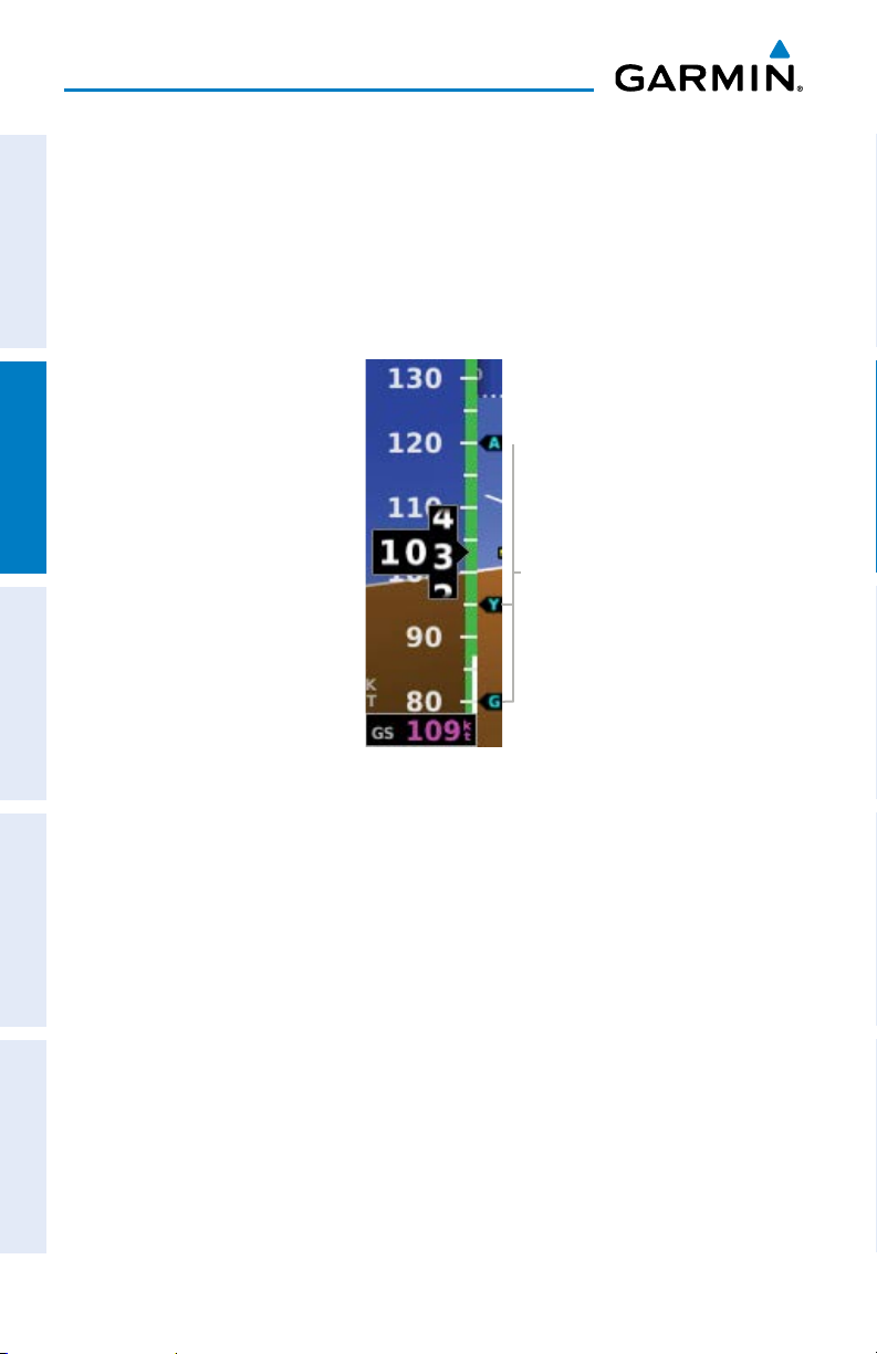
2.1.6 VERTICAL SPEED INDICATOR (VSI)
The Vertical Speed Indicator displays the aircraft vertical speed using a non-moving
tape with minor tick marks every 100 feet. The current vertical speed is displayed
using a white arrow along the tape. From the Air Data Page in configuration mode,
the Vertical Speed Indicator can be configured to display ± 1500 fpm, ± 2000 fpm, or
± 3000 fpm (refer to the Installation Manual section for more information).
Current Vertical Speed
Figure 2-14 Vertical Speed Indicator
190-02072-00 Rev. G 21
G5 Electronic Flight Instrument Pilot's Guide for Non-Certified Aircraft
Page 34

Flight Instruments
2.1.7 PFD PITCH ATTITUDE OFFSET
NOTE: PFD Pitch Attitude Offset can be configured as disabled in configuration
mode.
The Pitch attitude offset function allows the yellow aircraft symbol on the attitude
System OverviewFlight InstrumentsAFCSAdditional FeaturesIndex
indicator to be adjusted up or down much like the aircraft on a mechanical attitude
indicator. The pitch attitude can be adjusted as much as ± 5°. The pitch offset is
synchronized between the G5 and the other displays in a G3X/G3X Touch system. This
function can be disabled in configuration mode.
Changing the PFD pitch attitude offset:
1)
From the PFD Page, press the Knob to display the Menu.
2)
Select Pitch and use the Knob to select the desired Pitch Offset.
Cen
tering the PFD pitch attitude offset:
1)
From the PFD Page, press the Knob to display the Menu.
2)
Select Pitch and press and hold the Knob to center the Pitch Offset.
Figure 2-15 Pitch Offset
22
G5 Electronic Flight Instrument Pilot's Guide for Non-Certified Aircraft
190-02072-00 Rev. G
Page 35

Flight Instruments
BATT
2.1.8 BATTERY STATUS INDICATOR
System Overview Flight Instruments AFCS Additional Features Index
The current charge level of the battery is indicated by the filled-in portion of the
battery icon. The battery icon turns yellow or red to indicate a low-battery condition.
3:15
1:31
0:38
41%-100%
21%-40%
0%-20%
When the G5 is powered by the battery, the estimated time until the battery is empty
is displayed. Otherwise, the current charge level of the battery in percent is displayed
as a numeric value.
When the G5 is connected to external power and the battery is being charged, a
lightning bolt symbol appears over the battery icon.
92%
Charging
Other battery indications:
Battery charger hardware fault, or temperature too high/low to
safely charge the battery. The system is running on external power
but cannot charge the battery.
Battery fault.
NO BATT
190-02072-00 Rev. G 23
Battery is not present (appears only when the battery status field
has been configured to always appear).
G5 Electronic Flight Instrument Pilot's Guide for Non-Certified Aircraft
Page 36

Flight Instruments
2.2 HSI PAGE
NOTE: The HSI Page can be configured as disabled in configuration mode.
14
13
System OverviewFlight InstrumentsAFCSAdditional FeaturesIndex
1
2
3
4
5
6
7
1
Distance To Waypoint
2
Battery Status Indicator
3
Navigation Source
4
Aircraft Symbol
5
Navigator Messages
6
Rotating Compass Rose
7
Ground Speed
Selected Heading or
8
Ground Track
9
OBS Annunciator
Course Deviation Indica-
10
tor (CDI)
11
GPS CDI Scale
Selected Heading/Ground
12
Track Bug
Current Heading/Ground
13
Track
14
Current Track
Figure 2-16 Horizontal Situation Indicator (HSI)
12
11
10
9
8
24
G5 Electronic Flight Instrument Pilot's Guide for Non-Certified Aircraft
190-02072-00 Rev. G
Page 37

Flight Instruments
Table 2-1 Annunciations
Nav Source Annunciations
3
GPS CDI Scale Annunciations
11
System Overview Flight Instruments AFCS Additional Features Index
LP LPV LNAV
GPS/
GPS1/
GPS2
VLOC/
VLOC1/
VLOC2
VOR/
VOR1/
VOR2
LOC/
LOC1/
LOC2
LNAV/VNAV LNAV+V APR
TERM ENR OCN
VFR (0.25nm, 1.25nm, 5.00nm)
Navigator Messages Annunciations
5
LOI Loss of GPS Integrity MSG Pending Nav Message
DR GPS Dead-Reckoning Mode WPT Waypoint Arrival
NOTE: The VFR CDI Scale is displayed when the G5 is connected to a GPS
navigator via RS-232 only, or if ARINC 429 GPS navigation data is unavailable.
2.2.1 HORIZONTAL SITUATION INDICATOR (HSI)
The Horizontal Situation Indicator (HSI) on the HSI Page displays a rotating compass
card in a heading-up orientation. Letters indicate the cardinal points and numeric
labels occur every 30˚. Major tick marks are at 10˚ intervals and minor tick marks at
5˚ intervals. The current track is represented on the HSI by magenta triangle and a
dashed line. The HSI also presents course deviation, bearing, and navigation source
information.
Displaying the HSI page from the PFD page:
1)
From the PFD Page press the Knob to display the Menu.
2)
Select HSI.
190-02072-00 Rev. G 25
G5 Electronic Flight Instrument Pilot's Guide for Non-Certified Aircraft
Page 38

Flight Instruments
2.2.1.1 BEARING POINTER
A bearing pointer can be displayed on the HSI for NAV (VOR) and GPS sources. The
bearing pointer is light blue. The bearing pointer never overrides the CDI and is visually
separated from the CDI by a white ring (shown when the bearing pointer is selected
but not necessarily visible due to data unavailability).
System OverviewFlight InstrumentsAFCSAdditional FeaturesIndex
Bearing
Pointer
Figure 2-17 HSI Page with Bearing Pointer
Enabling/disabling the bearing pointer:
1)
From the HSI Page, press the Knob to display the Menu.
2)
Turn the Knob to highlight Bearing Pointer.
3)
Press the Knob to enable or disable the Bearing Pointer.
26
G5 Electronic Flight Instrument Pilot's Guide for Non-Certified Aircraft
190-02072-00 Rev. G
Page 39

Flight Instruments
Figure 2-18 Bearing Pointer Menu Option
2.2.1.2 COURSE DEVIATION INDICATOR (CDI)
The HSI contains a Course Deviation Indicator (CDI) with a Course Pointer. The
course pointer (GPS or VLOC) points in the direction of the selected course.
System Overview Flight Instruments AFCS Additional Features Index
The Course Deviation Indicator (CDI) moves left or right from the course pointer
along a lateral deviation scale to display aircraft position relative to the course. If the
course deviation data is not valid, the CDI is not displayed.
The CDI is capable of displaying multiple sources of navigation (GPS, VLOC, or both)
depending on the external navigator(s) configured (refer to the G5 Installation Manual
Section for more information). Color indicates the current navigation source: magenta
(for GPS) or green (for VOR and LOC). The full-scale limits for the CDI are defined by a
GPS-derived distance when coupled to GPS. When coupled to a VOR or localizer (LOC),
the CDI has the same angular limits as a mechanical CDI.
190-02072-00 Rev. G 27
G5 Electronic Flight Instrument Pilot's Guide for Non-Certified Aircraft
Page 40

Flight Instruments
2.2.2 HEADING/GROUND TRACK (HSI PAGE)
The Selected Heading or Ground Track is shown to the right of the HSI. The light blue
bug (heading) or magenta bug (ground track) on the compass rose corresponds to the
Selected Heading or Ground Track.
System OverviewFlight InstrumentsAFCSAdditional FeaturesIndex
NOTE: Heading is displayed if magnetometer data is available from a magnetometer via the CAN network. Otherwise, Ground Track is displayed.
Adj
usting the selected heading or ground track from the HSI page:
Use the HDG Knob on the GMC 307.
O
r
From the HSI Page, turn the Knob to adjust the selected heading or ground
track.
Syn
cing to the current heading or ground track from the HSI page:
Press the HDG Knob on the GMC 307.
O
r
From the HSI Page, press and hold the Knob to sync to the current heading
or ground track.
28
G5 Electronic Flight Instrument Pilot's Guide for Non-Certified Aircraft
190-02072-00 Rev. G
Page 41

Flight Instruments
2.3 NAVIGATION
System Overview Flight Instruments AFCS Additional Features Index
A G5 installed as part of a G3X system with multiple navigation sources will only
display data from the #1 navigation source. If the navigation source is a GNS/GTN
unit, both GPS and VLOC data can be displayed. Displayed navigation information is
also dependent upon the selection on the navigation configuration page.
Table 2-2 Navigation Data Functions
Installation Type Setting Navigation Data Behavior
G3X System Backup (with
Navigation Data configuration
mode set to 'Auto')
Displays navigation data from the external
navigator selected on the G3X PFD. Navigation
data from the G3X internal flight plan is not
displayed on the G5.
If multiple navigation sources are configured and
no G3X displays are present, the G5 can select
which source is displayed.
G3X System Backup (with
Navigation Data configuration
mode set to 'Always Display')
Always displays navigation data from navigation
source #1. This configuration is only applicable
when a single external navigator is configured.
Displays navigation data only when the
navigation data source selected on the G3X PFD
is the same as the navigation data available to
the G5. (If no G3X displays are present, this will
function as if Navigation Data is set to Always)
Standalone Instrument
Always displays navigation data. If multiple
navigation sources are configured, the G5 can
select which source is displayed.
190-02072-00 Rev. G 29
G5 Electronic Flight Instrument Pilot's Guide for Non-Certified Aircraft
Page 42

Flight Instruments
2.3.1 COURSE DEVIATION INDICATOR (CDI)
The PFD Page displays the Course Deviation Indicator (CDI) below the slip/skid
indicator. The HSI Page displays the CDI on the Horizontal Situation Indicator.
The Course Deviation Indicator (CDI) move left or right along a lateral deviation
scale to display the aircraft position relative to the course. If the course deviation data
System OverviewFlight InstrumentsAFCSAdditional FeaturesIndex
is not valid, the CDI is not displayed.
The CDI is capable of displaying multiple sources of navigation (GPS, VLOC, or both)
depending on the external navigator(s) configured (refer to the G5 Installation Manual
Section for more information). Color indicates the current navigation source: magenta
(for GPS) or green (for VOR and LOC). The full-scale limits for the CDI are defined by a
GPS-derived distance when coupled to GPS. When coupled to a VOR or localizer (LOC),
the CDI has the same angular limits as a mechanical CDI.
Course
Deviation
Indicator
Figure 2-19 Course Deviation Indicator (PFD Page)
Figure 2-20 Course Deviation Indicator (HSI Page)
30
G5 Electronic Flight Instrument Pilot's Guide for Non-Certified Aircraft
Course
Deviation
Indicator
190-02072-00 Rev. G
Page 43

Flight Instruments
Changing the navigation source on the external navigator (GPS,
VOR, LOC, or VLOC):
Use the associated external navigator to toggle between GPS and VOR/LOC
source types. Refer to the appropriate external navigator Pilot's Guide for
more information.
Changing the navigation source on the G5 (GPS, VOR, LOC, or
VLOC):
Refer to the G5 Installation Manual for information on configuring multiple
navigation sources.
1)
From the PFD Page, press the Knob to display the Menu.
2)
Turn the knob to select Source.
3)
Press the knob to cycle through available navigation sources.
System Overview Flight Instruments AFCS Additional Features Index
Navigation
Source
Figure 2-21 Navigation 'Source' Menu Option (PFD Page)
190-02072-00 Rev. G 31
G5 Electronic Flight Instrument Pilot's Guide for Non-Certified Aircraft
Page 44

Flight Instruments
2.3.2 VERTICAL DEVIATION INDICATOR AND VNAV
INDICATOR
NOTE: An external navigator (i.e. GTN/GNS, GNC 255, or SL30 Nav/Comm
Transceiver) must be configured to receive glideslope and/or glidepath vertical
System OverviewFlight InstrumentsAFCSAdditional FeaturesIndex
deviation indications.
Vertical
Deviation
Indicator
Vertical
Deviation
Indicator
Figure 2-22 Vertical Deviation
Indicator Position (PFD Page)
32
G5 Electronic Flight Instrument Pilot's Guide for Non-Certified Aircraft
Figure 2-23 Vertical Deviation
Indicator Position (HSI Page)
190-02072-00 Rev. G
Page 45

Flight Instruments
2.3.2.1 GLIDESLOPE - ILS SOURCE
The Vertical Deviation (Glideslope) Indicator (VDI) appears to the left of the altimeter
whenever an ILS frequency is tuned in the active NAV field of an external navigator.
A green diamond acts as the VDI Indicator, like a glideslope needle on a conventional
indicator. If a localizer frequency is tuned and there is no glideslope signal, “NO GS”
is annunciated.
Vertical
Deviation
Indicator
Figure 2-24 Vertical Deviation
Indicator (Glideslope-ILS Source)
System Overview Flight Instruments AFCS Additional Features Index
190-02072-00 Rev. G 33
G5 Electronic Flight Instrument Pilot's Guide for Non-Certified Aircraft
Page 46

Flight Instruments
2.3.2.2 GLIDEPATH - GPS SOURCE
The Vertical Deviation (Glidepath) Indicator (VDI) also appears to the left of the
altimeter during a GPS approach. The glidepath is analogous to the glideslope for
GPS approaches supporting WAAS vertical guidance (LNAV+V, L/VNAV, LPV). The
Glidepath Indicator appears on the G5 as a magenta diamond. If the approach type
System OverviewFlight InstrumentsAFCSAdditional FeaturesIndex
downgrades past the final approach fix (FAF), “NO GP” is annunciated.
Vertical
Deviation
Source
Vertical
Deviation
Indicator
Figure 2-25 Vertical Deviation
Indicator (Glidepath-GPS Source)
34
G5 Electronic Flight Instrument Pilot's Guide for Non-Certified Aircraft
190-02072-00 Rev. G
Page 47

Flight Instruments
2.3.2.3 VNAV INDICATOR
NOTE: VNAV deviation is only displayed when the G5 is receiving NMEA
RS-232 data from a portable GPS.
The magenta chevron (VNAV Indicator) to the left of the altimeter on the Vertical
Deviation Scale displays the VNAV profile.
VNAV
Indicator
Figure 2-26 VNAV Indicator
System Overview Flight Instruments AFCS Additional Features Index
190-02072-00 Rev. G 35
G5 Electronic Flight Instrument Pilot's Guide for Non-Certified Aircraft
Page 48

Flight Instruments
2.3.3 COURSE SELECTION
When the G5 is receiving VOR, LOC, or GPS data, a Course menu option is displayed.
Setting the course for a VOR or localizer:
1)
From the PFD Page, press the Knob to display the Menu.
System OverviewFlight InstrumentsAFCSAdditional FeaturesIndex
2)
Select Course and use the Knob to adjust the course.
Figure 2-27 VLOC Course on PFD Page
Setting the OBS course:
1)
From the PFD Page, press the Knob to display the Menu.
2)
Select Course and use the Knob to adjust the course.
36
G5 Electronic Flight Instrument Pilot's Guide for Non-Certified Aircraft
190-02072-00 Rev. G
Page 49

AFCS
SECTION 3 AUTOMATIC FLIGHT CONTROL
System Overview Flight Instruments AFCS Additional Features Index
SYSTEM (OPTIONAL)
NOTE: The approved Pilot’s Operating Handbook (POH) always supersedes
the information in this Pilot’s Guide.
NOTE: Refer to the approved Pilot’s Operating Handbook (POH) for emergency
procedures.
NOTE: A GMC controller is required for G5 AFCS functionality.
3.1 AFCS SYSTEM ARCHITECTURE
An Automatic Flight Control System (AFCS) is typically comprised of two major
components: A Flight Director (FD) and Autopilot servos. The Flight Director provides
pitch and roll commands to the autopilot servos. These pitch and roll commands are
displayed on the PFD Page as Command Bars. When the Flight Director is active the
pitch and roll commands can be hand-flown by the pilot or when coupled with the
autopilot, the autopilot servos drive the flight controls to follow the commands issued
by the Flight Director. The Flight Director operates independently of the autopilot
servos, but in most cases the autopilot servos can not operate independent of the
Flight Director.
3.1.1 AUTOPILOT AND YAW DAMPER OPERATION
The autopilot and optional yaw damper operate the flight control surface servos
to provide automatic flight control. The autopilot controls the aircraft pitch and roll
attitudes following commands received from the flight director. Pitch, Roll, and Yaw
(if installed) autotrim provides trim commands to each servo to relieve any sustained
effort required by the servo(s). Autopilot operation is independent of the optional yaw
damper.
190-02072-00 Rev. G 37
G5 Electronic Flight Instrument Pilot's Guide for Non-Certified Aircraft
Page 50

AFCS
The optional yaw damper reduces Dutch roll tendencies, coordinates turns, and
provides a steady force to maintain directional trim. It can operate independently
of the autopilot and may be used during normal hand-flight maneuvers. Yaw rate
commands are limited to 6 deg/sec by the yaw damper.
3.1.2 FLIGHT CONTROL
System OverviewFlight InstrumentsAFCSAdditional FeaturesIndex
Pitch and roll commands are provided to the servos based on the active flight
director modes. Yaw commands are provided by the yaw servo. Servo motor control
limits the maximum servo speed and torque. This allows the servos to be overridden
in case of an emergency.
3.1.3 PITCH AXIS AND TRIM
The autopilot pitch axis uses pitch rate to stabilize the aircraft pitch attitude during
flight director maneuvers. Flight director pitch commands are rate and attitude-limited,
combined with pitch damper control, and sent to the pitch servo motor. The pitch servo
measures the output effort (torque) and optionally provides this signal to the pitch trim
motor. The pitch servo commands the pitch trim motor to reduce the average pitch
servo effort.
3.1.4 ROLL AXIS
The autopilot roll axis uses roll rate to stabilize aircraft roll attitude during flight
director maneuvers. The flight director roll commands are rate- and attitude-limited,
combined with roll damper control, and sent to the roll servo motor.
3.1.5 YAW AXIS
The yaw damper uses yaw rate and roll attitude to dampen the aircraft’s natural
Dutch roll response. It also uses lateral acceleration to coordinate turns and reduce
or eliminate the need for the pilot to use rudder pedal force to maintain coordinated
flight during climbs and descents.
38
G5 Electronic Flight Instrument Pilot's Guide for Non-Certified Aircraft
190-02072-00 Rev. G
Page 51

AFCS
3.1.6 CONTROL WHEEL STEERING (CWS) (OPTIONAL)
Control Wheel Steering allows the aircraft to be hand-flown without disengaging the
AFCS. Press and hold the autopilot CWS Button (if equipped) to temporarily disengage
the pitch and roll servos from the flight control surfaces and hand-fly the aircraft.
The G5 autopilot control is synchronized to the aircraft attitude during Control Wheel
Steering. The green ‘AP’ annunciation is temporarily replaced by a white ‘CW’ for the
duration of Control Wheel Steering maneuvers.
In most scenarios, releasing the CWS Button reengages the Autopilot with a new
reference. Refer to (Vertical Modes) and (Lateral Modes) for Control Wheel Steering
behavior in each mode.
3.1.7 G5 AFCS STATUS BOX
The AFCS status box displays Autopilot (AP) and Flight Director (FD) mode
annunciations on the PFD Page.
Autopilot (AP) status is displayed middle of the G5 Autopilot Status Box. Lateral
modes are displayed on the left, and vertical modes are displayed on the right. Armed
modes are displayed in white and active in green.
Autopilot
Status
Active
Active Armed
System Overview Flight Instruments AFCS Additional Features Index
Figure 3-1 Autopilot Status Box
190-02072-00 Rev. G 39
G5 Electronic Flight Instrument Pilot's Guide for Non-Certified Aircraft
Page 52

AFCS
3.1.8 G5 AFCS CONFIGURATION
The G5 can be configured as a standalone unit or as a backup unit for a G3X or G3X
Touch system.
When configured as a standalone unit with a GMC controller and GSA servos:
• The G5 supports the following modes: LVL, PIT, ROL, HDG (for installations with a
System OverviewFlight InstrumentsAFCSAdditional FeaturesIndex
magnetometer), TRK (for installations without a magnetometer), GPS, VS, IAS, ALT, ALTS,
GP, and VNAV.
• GP mode requires ARINC 429 data from an IFR navigator.
• VNAV mode requires RS-232 data from a portable GPS.
When configured as a backup unit for a G3X or G3X Touch system:
• The G5 supports the following modes: LVL, PIT, ROL, HDG, TRK, GPS, VS, IAS,
ALT, ALTS, TO, GA, and GP.
• GP mode requires ARINC 429 data from an IFR navigator.
• TRK mode is selected using the HDG Button on the GMC and is only available
when magnetic heading is unavailable.
3.1.9 AFCS OPERATION
NOTE: When the G5 is configured as part of a G3X/G3X Touch system, the
G5 can be used to drive the autopilot and flight director only when all GDUs
are removed from the network.
AFCS functionality is distributed across the following Line Replaceable Units (LRUs):
•GMC305/307AFCSModeControlUnit
•GSA 28 AFCS Pitch/Roll/Yaw Damper (optional) servos.
The AFCS system can be divided into these main operating functions:
• Flight Director (FD) — Flight director commands are displayed on the display
The flight director provides:
– Command Bars showing pitch/roll guidance
– Vertical/lateral mode selection and processing
– Autopilot communication
40
G5 Electronic Flight Instrument Pilot's Guide for Non-Certified Aircraft
190-02072-00 Rev. G
Page 53

AFCS
•Autopilot (AP) — Autopilot operation occurs within the pitch and roll servos.
It also provides servo monitoring and automatic flight control in response to flight
System Overview Flight Instruments AFCS Additional Features Index
director steering commands, Air Data and Attitude and Heading Reference System
(ADAHRS) attitude, rate information, and airspeed.
•Yaw Damper (YD) — The yaw servo (optional), is self-monitoring and provides
Dutch roll damping and turn coordination in response to yaw rate, roll angle, lateral
acceleration, and airspeed. If installed the YD comes on when the autopilot is engaged
and stays on after disengaging the autopilot. The YD can be turned on/off independent
of the autopilot using the YD Key.
•Manual Electric Trim (MET) — Manual electric trim may provide trim capability
for any properly configured axis (pitch, roll, or yaw) when the autopilot is not engaged.
NOTE: Refer to the G5 Installation Manual Section for information on installing and configuring the G5 Integrated Autopilot Interface.
3.1.10 AFCS PRE-FLIGHT ACTIONS (STANDALONE
INSTALLATION)
To ensure that the Automatic Flight Control System (AFCS) is operating properly
prior to flight, perform the following Garmin recommended preflight checks.
Before takeoff checklist:
1)
Autopilot - ENGAGE (using AP/CWS button, or AP button on mode
controller)
2)
Flight controls - CHECK (verify autopilot can be overpowered in both pitch
and roll)
3)
AP DISC button - PRESS (verify autopilot disengages)
4)
Yaw damper - OFF (if installed) (verify yaw damper disengages)
5)
Flight director - SET FOR TAKEOFF (select IAS or VS mode or push FD Button
to turn off the Flight Director)
6)
Flight controls - CHECK (verify autopilot servos are disengaged from pitch,
roll, and yaw controls, and all controls move freely)
7)
Elevator trim control - SET FOR TAKEOFF
190-02072-00 Rev. G 41
G5 Electronic Flight Instrument Pilot's Guide for Non-Certified Aircraft
Page 54

AFCS
3.1.11 AFCS CONTROLS
3.1.11.1 GMC 305/307 AFCS CONTROLS
The GMC 305/307 AFCS Control Units have the following controls:
System OverviewFlight InstrumentsAFCSAdditional FeaturesIndex
Table 3-1 AFCS Controls
1
HDG Key Selects/deselects Heading Select Mode. (Used for TRK
Mode in installations without a magnetometer)
2
NAV Key Selects/deselects Navigation Mode. Cancels GP Mode if
GPS Mode is either active or armed.
3
AP Key Engages/disengages the autopilot
4
LVL (Level) Key Engages the autopilot (if the autopilot is disengaged) in
level vertical and lateral modes
5
NOSE UP/DN
Wheel
6
IAS Key Selects/deselects Indicated Airspeed Mode
7
ALT Key Selects/deselects Altitude Hold Mode
8
VNV Key Selects/deselects Vertical Path Tracking Mode for Vertical
Adjusts the vertical mode reference in Pitch Hold, Vertical
Speed, Indicated Airspeed, and Altitude Hold modes
Navigation flight control
9
VS Key Selects/deselects Vertical Speed Mode
10
YD Key (if installed) Engages/disengages the yaw damper
11
FD Key Activates/deactivates the flight director only
Pressing once turns on the director in the default vertical
and lateral modes. Pressing again deactivates the
flight director and removes the Command Bars. If the
autopilot is engaged, the key is disabled.
12
APR Key Selects/deselects Approach Mode (GP mode only)
13
HDG Knob Selects the desired Heading*
14
ALT SEL Knob Selects the desired Altitude setting*
*GMC 307 only
42
G5 Electronic Flight Instrument Pilot's Guide for Non-Certified Aircraft
190-02072-00 Rev. G
Page 55

AFCS
1 2 3 4 5 6 7
Active
Mode
10 912 11
Figure 3-2 GMC 305 AFCS Control Unit
13 12 3 4 5 14
6
System Overview Flight Instruments AFCS Additional Features Index
8
710 91 11
82
Figure 3-3 GMC 307 AFCS Control Unit
190-02072-00 Rev. G 43
G5 Electronic Flight Instrument Pilot's Guide for Non-Certified Aircraft
Page 56

AFCS
The following AFCS controls are located separately from the G5 and GMC 305/307
AFCS Control Unit:
Table 3-2 Other AFCS Controls
CWS/AP DISC Button
(Autopilot Disconnect)
System OverviewFlight InstrumentsAFCSAdditional FeaturesIndex
An AP DISC/CWS Button is located on the pilot’s control
stick. This button combines the functions of Autopilot
Disconnect and Control Wheel Steering. (Note: the Control
Wheel Steering function can be disabled in configuration
mode, which causes the button to perform the Autopilot
Disconnect function only)
Press and release the AP DISC/CWS Button to disengage
the autopilot.
Pressing and holding the AP DISC/CWS Button when
the autopilot is engaged will temporarily disengage the
pitch and roll servos and interrupt autotrim operation.
The pilot can then hand-fly the aircraft to a new attitude
and release the AP DISC/CWS button to re-engage the
autopilot servos and synchronize the flight director to the
aircraft’s new attitude. The ability to use Control Wheel
Steering may be disabled in configuration mode if desired.
If the configuration supports it, pressing and holding the
AP DISC/CWS button while the autopilot is not engaged
will cause the autopilot to engage. If the flight director
was previously off, the default FD modes (PIT and ROL)
will be selected. The ability to engage the autopilot using
the CWS button may be disabled in configuration mode if
desired.
TO/GA Button
(Takeoff/Go Around)
Selects flight director Takeoff or Go Around Mode (only
applies to a G5 installed as part of a G3X/G3X Touch
system).
MET Switch
(Manual Electric Trim)
Used to command manual electric trim for any properly
configured servo (pitch, roll, or yaw).
44
G5 Electronic Flight Instrument Pilot's Guide for Non-Certified Aircraft
190-02072-00 Rev. G
Page 57

AFCS
3.1.11.2 ENGAGING THE AUTOPILOT
System Overview Flight Instruments AFCS Additional Features Index
Selection of the control listed below (when the Autopilot is not engaged) will engage
the Autopilot with the listed lateral and vertical modes (some modes may require an
external navigator):
Table 3-3 Engaging the Autopilot
Modes Selected
Control
Lateral Vertical
Mode/Annunciation Mode/Annunciation
CWS Button (if equipped)
(press and hold)
Roll Hold ROL Pitch Hold PIT
HDG Heading HDG Pitch Hold PIT
NAV Navigation GPS Pitch Hold PIT
ALT Roll Hold ROL Altitude Hold A LT
VS Roll Hold ROL Vertical Speed VS
VNAV Roll Hold ROL Vertical Navigation VNAV
APPR Approach GPS Glidepath GP
Navigation and Approach Modes must have an active GPS course to activate the
autopilot.
3.1.11.2.1 enGaGinG the autopiLot (GmC 305/307)
An initial press of the AP Key on the GMC 305/307 will activate the Flight Director
and engage the autopilot in the default PIT and ROL modes.
190-02072-00 Rev. G 45
G5 Electronic Flight Instrument Pilot's Guide for Non-Certified Aircraft
Page 58

AFCS
3.1.11.3 DISENGAGING THE AUTOPILOT
The Autopilot is manually disengaged by pressing the autopilot disconnect button
on the control stick or yoke or by pressing the AP Key on the GMC 305/307. Manual
disengagement is indicated by a five-second flashing yellow ‘AP’ annunciation. Cancel
the aural alert by pressing and releasing the AP/CWS Button again.
System OverviewFlight InstrumentsAFCSAdditional FeaturesIndex
Automatic disengagement is indicated by a flashing red ‘AP’ annunciation. Automatic
disengagement occurs due to:
•System failure
•Invalid sensor data
•Inability to compute default autopilot modes
•Detection of a GDU display on the CAN network (when installed as part of a G3X/
G3X Touch system).
3.1.11.3.1 diSenGaGinG the autopiLot when a maLfunCtion iS
SuSpeCted
If an autopilot failure or trim failure is suspected to have occurred, perform the
following steps:
1)
Firmly grasp the control wheel.
2)
Press and hold the AP DISC Switch. The autopilot will disconnect and power
is removed from the trim motor. Power is also removed from all primary
servo motors and engaged solenoids. Note the visual alerting indicating
autopilot disconnect.
3)
Retrim the aircraft as needed. Substantial trim adjustment may be needed.
4)
Pull the appropriate circuit breaker(s) to electrically isolate the servo and
solenoid components.
5)
Release the AP DISC Switch.
46
G5 Electronic Flight Instrument Pilot's Guide for Non-Certified Aircraft
190-02072-00 Rev. G
Page 59

AFCS
3.1.11.3.2 overpowerinG autopiLot ServoS
System Overview Flight Instruments AFCS Additional Features Index
In the context of this discussion, “overpowering” refers to any pressure or force
applied to the pitch controls when the autopilot is engaged. A small amount of
pressure or force on the pitch controls can cause the autopilot automatic trim to run to
an out-of-trim condition. Therefore, any application of pressure or force to the controls
should be avoided when the autopilot is engaged.
Overpowering the autopilot during flight will cause the autopilot’s automatic trim to
run, resulting in an out-of-trim condition or cause the trim to hit the stop if the action
is prolonged. In this case, larger than anticipated control forces may be required after
the autopilot is disengaged.
The following steps should be added to the preflight check:
1)
Check for proper autopilot operation and ensure the autopilot can be
overpowered.
2)
Note the forces required to overpower the autopilot servo clutches.
3.1.12 FLIGHT DIRECTOR OPERATION
NOTE: Refer to the Installation Manual section for AFCS setup information.
The flight director function provides pitch and roll commands to the pilot and
autopilot, which are displayed on the PFD Page. With the flight director active, the
aircraft can be hand-flown to follow the path shown by the Command Bars. The Flight
Director has the following maximum commands: pitch (-15°, +20°) and roll (30°)
angles.
190-02072-00 Rev. G 47
G5 Electronic Flight Instrument Pilot's Guide for Non-Certified Aircraft
Page 60

AFCS
3.1.12.1 ACTIVATING THE FLIGHT DIRECTOR
An initial press of a key listed in the table below (when the flight director is not
active) activates the flight director in the listed modes. The flight director may be
turned off and the Command Bars removed from the display by pressing the FD Key
again. The FD Key is disabled when the autopilot is engaged.
System OverviewFlight InstrumentsAFCSAdditional FeaturesIndex
Table 3-4 Flight Director Activation (GMC 305/307)
Control Pressed
Modes Selected
Lateral Vertical
FD Key Roll Hold (default) ROL Pitch Hold (default) PIT
AP Key Roll Hold (default) ROL Pitch Hold (default) PIT
TO/GA Button
Takeoff (on-ground)
Go Around (in-air)
TO GATakeoff (on-ground)
Go Around (in-air)
TO
GA
ALT Key Roll Hold (default) ROL Altitude Hold ALT
VS Key Roll Hold (default) ROL Vertical Speed VS
VNV Key Roll Hold (default) ROL Vertical Navigation* VNV
IAS Key Roll Hold (default) ROL Indicated Airspeed IAS
APR Key Approach** GPS Pitch Hold (default) PIT
NAV Key Navigation** GPS Pitch Hold (default) PIT
HDG Key Heading Select HDG*** Pitch Hold (default) PIT
LVL Key Level Hold LVL Level Hold LVL
*Must be receiving VNAV data from a portable GPS via RS-232 before VNV Key press activates flight
director.
**The selected navigation receiver must have an active GPS course before
activates flight director.
*** HDG mode is only available when magnetic heading data is being received from an ADAHRS unit,
when the G5 is installed as a backup unit in a G3X/G3X Touch system.
NAV
or
APR
Key press
48
G5 Electronic Flight Instrument Pilot's Guide for Non-Certified Aircraft
190-02072-00 Rev. G
Page 61

AFCS
3.1.12.2 FLIGHT DIRECTOR MODES
System Overview Flight Instruments AFCS Additional Features Index
Flight director modes are normally selected independently for the pitch and roll axes.
Unless otherwise specified, all mode keys are alternate action (i.e., press on, press off).
In the absence of specific mode selection, the flight director reverts to the default pitch
and/or roll modes.
Armed modes are annunciated in white and active in green in the AFCS Status Box.
Under normal operation, when the control for the active flight director mode is pressed,
the flight director reverts to the default mode(s) for the axis(es). Automatic transition
from armed to active mode is indicated by the white armed mode annunciation moving
to the green active mode field and flashing for 10 seconds.
If the information required to compute a flight director mode becomes invalid or
unavailable, the flight director automatically reverts to the default mode for that axis.
A flashing yellow mode annunciation and annunciator light indicate loss of sensor or
navigation data required to compute commands. When such a loss occurs, the system
automatically begins to roll the wings level (enters Roll Hold Mode) or maintain the
pitch angle (enters Pitch Hold Mode), depending on the affected axis. The flashing
annunciation stops when the affected mode key is pressed or another mode for the
axis is selected. If after 10 seconds no action is taken, the flashing annunciation stops.
The flight director is automatically disabled if the attitude information required to
compute the default flight director modes becomes invalid or unavailable.
190-02072-00 Rev. G 49
G5 Electronic Flight Instrument Pilot's Guide for Non-Certified Aircraft
Page 62

AFCS
3.1.12.3 COMMAND BARS
Upon activation of the flight director, Command Bars are displayed in magenta on
the PFD Page. If the aircraft is being flown by hand, the command bars are displayed
hollow. The Command Bars do not override the Aircraft Symbol. The Command Bars
move together vertically to indicate pitch commands and bank left or right to indicate
System OverviewFlight InstrumentsAFCSAdditional FeaturesIndex
roll commands.
Hollow Command Bars (Pilot Hand Flying Aircraft, FD Only)
Solid Command Bars (Autopilot Engaged)
Aircraft Symbol
Figure 3-4 Command Bars (Single Cue Flight Director)
Flight
Director
Figure 3-5 Flight Director (Dual Cue)
If the attitude information being sent to the flight director becomes invalid or
unavailable, the Command Bars are removed from the display.
50
G5 Electronic Flight Instrument Pilot's Guide for Non-Certified Aircraft
190-02072-00 Rev. G
Page 63

AFCS
3.1.12.4 FLIGHT DIRECTOR ALTITUDE CONTROLS
CAUTION: The following settings change the Flight Director operation. Before
changing these settings become familiar with how these changes affect the
use of the Flight Director.
NOTE: Refer to the Installation Manual section for information on changing
the Flight Director Altitude Controls.
The Flight Director Altitude Controls allow the user to select Normal or Simplified.
When Altitude Controls are set to Normal, the following additional selections
appear:
• ALT Mode User Select Action: Determines the behavior of the Flight Director
when the user selects Altitude Hold Mode by pressing the ALT key on the GMC.
The following two options are available:
• Normal: The Flight Director enters Altitude Hold (ALT) Mode.
• Sync Selected Altitude: The Flight Director enters Altitude Hold (ALT)
Mode and the Selected Altitude (Altitude Bug) changes to the current
aircraft altitude.
• ALT Mode User Up/Down Action: Determines the behavior of the Flight
Director when the Flight Director is in Altitude Hold (ALT) Mode and the user
moves the pitch wheel on the GMC. The following two options are available:
System Overview Flight Instruments AFCS Additional Features Index
• Normal: Adjusts the Target Altitude in 10-foot increments, up to ±200
feet from the original Target Altitude.
• Select VS Mode: The Flight Director changes from Altitude Hold (ALT)
Mode to Vertical Speed (VS) Mode and initiates a climb or descent.
Subsequent vertical speed adjustments are in increments of 100 fpm. The
Default Vertical Speed that is used for the initial climb or descent is set
using a pair of fields that appear when Select VS Mode is selected.
When Altitude Controls are set to Simplified, Altitude Hold (ALT) Mode behavior
differs in the following ways:
190-02072-00 Rev. G 51
G5 Electronic Flight Instrument Pilot's Guide for Non-Certified Aircraft
Page 64

AFCS
NOTE: With Altitude Controls set to Simplified, the user will not be able to
pre-select a new altitude while ALT mode is already active.
• Selecting Altitude Hold (ALT) Mode causes the Selected Altitude (Altitude Bug)
to change to the current aircraft altitude.
System OverviewFlight InstrumentsAFCSAdditional FeaturesIndex
• There is no longer a difference between the Selected Altitude (Altitude Bug) and
the Target Altitude for Altitude Hold (ALT) Mode.
• After Altitude Hold (ALT) Mode captures the Selected Altitude, subsequent
changes to the Selected Altitude will cause ALT Mode to climb or descend
towards the new Selected Altitude.
• Subsequent vertical speed adjustments are in increments of 100 fpm, with
the exception that the user cannot adjust the target vertical speed to a
value that would cause the aircraft to fly away from the Selected Altitude.
• Unlike Select VS Mode described previously, this option does not switch
to VS mode. Instead, it displays a vertical speed bug.
• The initial vertical speed used for climb or descent towards the new altitude
is determined by the Default Vertical Speed fields as described previously.
• When Altitude Hold (ALT) Mode has captured the Selected Altitude, the vertical
speed bug is removed and vertical speed adjustments have no effect.
3.1.13 VERTICAL MODES
The table lists the vertical modes with their corresponding controls and annunciations.
The mode reference is displayed next to the active mode annunciation for Altitude
Hold, Vertical Speed, and Indicated Airspeed modes. The NOSE UP/DN Wheel can be
used to change the vertical mode reference while operating under Pitch Hold, Vertical
Speed, Indicated Airspeed, or Altitude Hold modes. Increments of change of values for
each of these references using the NOSE UP/DN Wheel, are also listed in the table.
52
G5 Electronic Flight Instrument Pilot's Guide for Non-Certified Aircraft
190-02072-00 Rev. G
Page 65

AFCS
Table 3-5 Flight Director Vertical Modes
Vertical
Mode
Description Control Annunciation
Reference
Change
Increment
Holds the current aircraft pitch
Pitch Hold
attitude; may be used to climb/
(default) PIT 0.5°
descend to the Selected Altitude
Selected
Altitude
Capture
Altitude
Hold
Captures the Selected Altitude * ALTS
10 ft
Holds the current Altitude ALT Key A LT
Maintains the current aircraft
Vertical
Speed
vertical speed; may be used to
climb/descend to the Selected
VS Key VS 100 fpm
Altitude
Indicated
Airspeed
(IAS)
Vertical
Navigation
Glidepath
Maintains the current aircraft
airspeed in IAS while the aircraft
is climbing/descending to the
Selected Altitude
Captures and tracks descent legs
of an active vertical profile
Captures and tracks the SBAS
glidepath on approach
IAS Key IAS 1 kt
VNV Key
(GMC
VNV***
305/307)
APR Key
(GMC
GP
305/307)
Commands a constant pitch
Takeoff
Go Around
* ALTS armed automatically when PIT, VS, IAS, or GA active, and under VNAV when Selected Altitude
is to be captured instead of VNV Target Altitude
** TO and GA modes are only displayed when the G5 is configured as a backup unit in a G3X/G3X
Touch system.
*** VNV mode (only available as part of a standalone G5 installation when receiving NMEA RS-232
data from a portable GPS).
angle and wings level on-ground
in preparation for takeoff
Commands a constant pitch
angle and wings level in the air
TO**
GA Button
GA**
System Overview Flight Instruments AFCS Additional Features Index
190-02072-00 Rev. G 53
G5 Electronic Flight Instrument Pilot's Guide for Non-Certified Aircraft
Page 66

AFCS
3.1.13.1 PITCH HOLD MODE (PIT)
When the flight director is activated (FD key pressed) or when the Autopilot is
activated, Pitch Hold Mode is selected by default. Pitch Hold Mode is indicated as the
active vertical mode by the green ‘PIT’ annunciation. This mode may be used for climb
or descent to the Selected Altitude (shown above the Altimeter), since Selected Altitude
System OverviewFlight InstrumentsAFCSAdditional FeaturesIndex
Capture Mode is automatically armed when Pitch Hold Mode is activated.
In Pitch Hold Mode, the flight director maintains a constant pitch attitude. The pitch
reference is set to the aircraft pitch attitude at the moment of mode selection. If the
aircraft pitch attitude exceeds the flight director pitch command limitations, the flight
director commands a pitch angle equal to the nose-up/down limit.
Changing the pitch reference:
When operating in Pitch Hold Mode, the pitch reference can be adjusted by
using the
Or
Hold the Control Wheel Steering (CWS) Button (if equipped, and the
autopilot unit supports CWS), establish the desired pitch attitude, then
release the CWS Button.
NOSE UP/DN
Wheel.
Pitch Hold
Mode Active
Selected Altitude
Capture Mode
Armed
Figure 3-6 Pitch Hold & Selected Altitude Capture Modes
54
G5 Electronic Flight Instrument Pilot's Guide for Non-Certified Aircraft
Selected
Altitude
190-02072-00 Rev. G
Page 67

AFCS
3.1.13.2 SELECTED ALTITUDE CAPTURE MODE (ALTS)
System Overview Flight Instruments AFCS Additional Features Index
Selected Altitude Capture Mode is automatically armed with activation of the
following modes:
•PitchHold
•VerticalSpeed
•TO/GoAround
•VerticalPathTracking
•IndicatedAirspeed
The white ‘ALTS’ annunciation indicates Selected Altitude Capture Mode is armed.
Figure 3-7 Selected Altitude Capture Mode (Armed)
As the aircraft nears the Selected Altitude, the flight director automatically transitions
to Selected Altitude Capture Mode with Altitude Hold Mode armed. This automatic
transition is indicated by the green ‘ALTS’ annunciation flashing for up to 10 seconds
and the appearance of the white ‘ALTS’ annunciation.
At 50 feet from the Selected Altitude, the flight director automatically transitions
from Selected Altitude Capture to Altitude Hold Mode and holds the reference altitude.
As Altitude Hold Mode becomes active, the white ‘ALTS’ annunciation moves to the
active vertical mode field and flashes green for 10 seconds to indicate the automatic
transition.
Setting the selected altitude:
Use the ALT SEL Knob on the GMC 307 to adjust the selected altitude.
O
r
1)
Press the Knob to display the Menu.
2)
Select Altitude and use the Knob to change the Selected Altitude.
Syncing to the current altitude:
Press the Knob on the GMC 307.
O
r
1)
Press the Knob to display the Menu.
2)
Select Altitude and press and hold the Knob to sync the Selected Altitude
to the current altitude
190-02072-00 Rev. G 55
G5 Electronic Flight Instrument Pilot's Guide for Non-Certified Aircraft
Page 68

AFCS
Changing the Selected Altitude while Selected Altitude Capture Mode is active
causes the autopilot to revert to Pitch Hold Mode with Selected Altitude Capture Mode
armed for the new Selected Altitude.
3.1.13.3 ALTITUDE HOLD MODE (ALT)
Altitude Hold Mode can be activated by pressing the
System OverviewFlight InstrumentsAFCSAdditional FeaturesIndex
ALT
Key; the AFCS maintains
the current aircraft altitude (to the nearest 10 feet) as the Altitude Reference. Altitude
Hold Mode active is indicated by a green ‘ALT’ annunciation in the G5 Autopilot Status
Box.
Altitude Hold Mode is automatically armed when in Selected Altitude Capture Mode.
Selected Altitude Capture Mode automatically transitions to Altitude Hold Mode when
within 50 feet of the Selected Altitude. In this case, the Selected Altitude becomes the
Altitude Reference.
3.1.13.3.1 ChanGinG the aLtitude referenCe
When operating in Altitude Hold Mode, the Altitude Reference can be adjusted in
the following ways:
•The Altitude Reference can be adjusted up or down in 10-foot increments
by rolling the NOSE UP/DN Wheel. Using this method, up to 200 feet of
altitude change can be commanded. To change the Altitude Reference by
more the 200 feet, use the CWS button (if equipped) as described below, or
climb/descend using another vertical mode (PIT, VS) to capture the desired
Selected Altitude.
•If the aircraft is equipped with a CWS Button, pressing the CWS Button allows
the aircraft to be hand-flown to a new Altitude Reference. When the CWS
Button is released at the desired altitude, the new altitude is established as
the Altitude Reference.
Altitude Hold
Mode Active
Figure 3-8 Altitude Hold Mode
56
G5 Electronic Flight Instrument Pilot's Guide for Non-Certified Aircraft
190-02072-00 Rev. G
Page 69

AFCS
3.1.13.4 VERTICAL SPEED MODE (VS)
System Overview Flight Instruments AFCS Additional Features Index
In Vertical Speed Mode, the flight director acquires and maintains a Vertical Speed
Reference. Current aircraft vertical speed (to the nearest 100 fpm) becomes the Vertical
Speed Reference at the moment of Vertical Speed Mode activation. This mode may be
used for climb or descent to the Selected Altitude (shown above the Altimeter) since
Selected Altitude Capture Mode is automatically armed when Vertical Speed Mode is
selected.
When Vertical Speed Mode is activated by pressing the VS Key, ‘VS’ is annunciated
in green in the Autopilot Status Box. The Vertical Speed Reference is also displayed
below the Vertical Speed Indicator. A Vertical Speed Reference Bug corresponding to
the Vertical Speed Reference is shown on the indicator.
Vertical Speed
Reference Bug
Vertical Speed
Reference
Figure 3-9 Vertical Speed Reference on PFD Page
190-02072-00 Rev. G 57
G5 Electronic Flight Instrument Pilot's Guide for Non-Certified Aircraft
Page 70

AFCS
3.1.13.4.1 ChanGinG the vertiCaL Speed referenCe
The Vertical Speed Reference may be adjusted in the following ways:
•Use the
NOSE UP/DN
Wheel to adjust the Vertical Speed Reference in
increments of 100 fpm.
•
System OverviewFlight InstrumentsAFCSAdditional FeaturesIndex
Press the CWS Button (if equipped) and hand-fly the aircraft to a new
Vertical Speed Reference. When the CWS Button is released, the aircraft’s
vertical speed (to the nearest 100 fpm) is established as the new Vertical
Speed Reference.
Vertical
Speed
Mode
Active
Figure 3-10 Vertical Speed Mode
3.1.13.5 INDICATED AIRSPEED MODE (IAS)
Indicated Airspeed
This mode acquires and maintains the Airspeed Reference (IAS) while climbing or
descending. When Indicated Airspeed Mode is active, the flight director continuously
monitors Selected Altitude, airspeed and altitude.
The Airspeed Reference is set to the current airspeed upon mode activation.
Indicated Airspeed Mode is indicated by a green ‘IAS’ annunciation in the Autopilot
Status Box. The Airspeed Reference is also displayed as a light blue bug corresponding
to the Airspeed Reference along the airspeed tape.
Mode is selected by pressing the
IAS
Key on the GMC.
Engine power must be adjusted to allow the autopilot to fly the aircraft at a pitch
attitude corresponding to the desired flight profile (climb or descent) while maintaining
the Airspeed Reference.
58
G5 Electronic Flight Instrument Pilot's Guide for Non-Certified Aircraft
190-02072-00 Rev. G
Page 71

AFCS
3.1.13.5.1 ChanGinG the airSpeed referenCe
The Airspeed Reference (shown in both the Autopilot Status Box and above the
Airspeed Indicator) may be adjusted by using the
Indicated
Airspeed
Reference
Indicated
Airspeed
Reference Bug
Figure 3-11 Indicated Airspeed Reference on PFD Page
NOSE UP/DN
Wheel.
3.1.13.6 VERTICAL NAVIGATION MODE (VNV)
NOTE: If another vertical mode is touched while VNV Mode is selected, VNV
Mode reverts to armed.
System Overview Flight Instruments AFCS Additional Features Index
NOTE: Pressing the CWS Button (if equipped) while VNV Mode is active does
not cancel the mode. The autopilot guides the aircraft back to the descent
path upon release of the CWS Button.
Vertical Navigation (VNV) Mode is available for enroute/terminal cruise and descent
operations any time that VNAV input data is being received.
Vertical
Navigation
Mode Active
Figure 3-12 Vertical Navigation Mode
190-02072-00 Rev. G 59
G5 Electronic Flight Instrument Pilot's Guide for Non-Certified Aircraft
Page 72

AFCS
Activating vertical navigation mode:
1)
When
a flight plan is active, VNAV data is valid, and the VNV Key is selected, VNV
mode is armed in preparation for descent path capture. ‘VNV’ is annunciated in
white in the G5 Autopilot Status Box.
2)
When a descent leg is captured (i.e., vertical deviation becomes valid), VNV Mode is
System OverviewFlight InstrumentsAFCSAdditional FeaturesIndex
activated and tracks the descent profile.
3)
Level off when approaching the Selected Altitude.
If the altimeter’s barometric setting is adjusted while VNV mode is active, the
autopilot increases/decreases the descent rate by up to 500 fpm to re-establish the
aircraft on the descent path (without commanding a climb). For large changes, it may
take several minutes for the aircraft to reestablish on the descent path.
3.1.13.6.1 automatiC reverSion to pitCh hoLd mode
Several situations can occur while VNV Mode is active which cause the AFCS
to revert to Pitch Hold Mode:
•
The aircraft does not level off at the selected altitude.
•
Vertical deviation exceeds 200 feet during an overspeed condition.
•
Vertical deviation becomes invalid (the Deviation Indicator is removed
from the PFD Page).
Following a reversion to Pitch Hold Mode, VNV Mode becomes armed to
allow for possible profile recapture.
60
G5 Electronic Flight Instrument Pilot's Guide for Non-Certified Aircraft
190-02072-00 Rev. G
Page 73

AFCS
3.1.13.7 GLIDEPATH MODE (GP) (WITH EXTERNAL WAAS
ENABLED IFR NAVIGATOR ONLY)
Glidepath Mode is used to track a WAAS or other satellite-based augmentation
system SBAS generated glidepath. When Glidepath Mode is armed, ‘GP’ is annunciated
in white in the Autopilot Status Box.
Selecting glidepath mode:
1)
EXTERNAL NAVIGATOR: Ensure a GPS approach with vertical guidance
(LPV, LNAV/VNAV, LNAV +V) is loaded into the active flight plan. The active
waypoint must be part of the flight plan (cannot be a direct-to a waypoint
not in the flight plan).
2)
Ensure that GPS is the selected navigation source.
3)
Press the APR Key.
NOTE: Some RNAV (GPS) approaches provide a vertical descent angle as an
aid in flying a stabilized approach. These approaches are NOT considered
Approaches with Vertical Guidance (APV). Approaches that are annunciated
on the HSI as LNAV or LNAV+V are considered Non-precision Approaches
(NPA) and are flown to an MDA even though vertical glidepath (GP) information may be provided.
WARNING: When flying an LNAV approach (with vertical descent angle)
with the autopilot coupled, the aircraft will not level off at the MDA even if
the MDA is set in the altitude preselect.
System Overview Flight Instruments AFCS Additional Features Index
Upon reaching the glidepath, the flight director transitions to Glidepath Mode and
begins to capture and track the glidepath.
Once the following conditions have been met, the glidepath can be captured:
•Theactivewaypointisatorafterthenalapproachx(FAF).
•Verticaldeviationisvalid.
•TheCDIisatlessthanfull-scaledeviation.
•Automaticsequencingofwaypointshasnotbeensuspended.
Glidepath
Mode Active
Figure 3-13 Glidepath Mode
190-02072-00 Rev. G 61
G5 Electronic Flight Instrument Pilot's Guide for Non-Certified Aircraft
Page 74

AFCS
3.1.13.8 GO AROUND (GA) AND TAKEOFF (TO) MODES
NOTE: TO and GA modes are only available when the G5 is configured as a
backup unit in a G3X/G3X Touch system.
Go Around and Takeoff modes are coupled pitch and roll modes and are annunciated
System OverviewFlight InstrumentsAFCSAdditional FeaturesIndex
as both the vertical and lateral modes when active. In these modes, the flight director
commands a constant set pitch attitude and keeps the wings level. The GA Switch
is used to activate both modes. The mode entered by the flight director depends on
whether the aircraft is on the ground or in the air.
Takeoff Mode provides an attitude reference during rotation and takeoff. This mode
can be selected only while on the ground by pushing the TO/GA Button. The flight
director Command Bars assume a wings-level, pitch-up attitude.
Pressing the TO/GA Button while in the air activates the flight director in a wingslevel, pitch-up attitude, allowing the execution of a missed approach or a go around.
Go Around Mode arms Selected Altitude Capture Mode automatically, and attempts to
modify the aircraft attitude (i.e., with the
to Pitch and Roll Hold modes.
NOSE UP/DN
Wheel) will result in reversion
62
G5 Electronic Flight Instrument Pilot's Guide for Non-Certified Aircraft
190-02072-00 Rev. G
Page 75

AFCS
3.1.14 LATERAL MODES
The following table lists the lateral modes and respective control(s) and annunciation.
Refer to the vertical modes section for information regarding Takeoff and Go Around
Modes.
Table 3-6 Flight Director Lateral Modes
Lateral Mode Description Control Annunciation
Holds the current aircraft roll
Roll Hold
Heading
(Installations with a
magnetometer)
Track
(Installations without a
magnetometer)
Navigation, GPS
Approach, GPS
Takeoff
Go Around
* TO, and GA modes are only available when the G5 is configured as a backup unit in a G3X/G3X
Touch system.
attitude or rolls the wings level,
depending on the commanded
bank angle
Captures and tracks the
Selected Heading
Captures and tracks the
Selected Ground Track
Captures and tracks the
selected navigation source
(GPS)
Captures and tracks the
selected navigation source
(GPS)
Commands a constant pitch
angle and wings level onground in preparation for
takeoff
Commands a constant pitch
angle and wings level in the air
(default) ROL
HDG Key HDG
HDG Key TRK
NAV Key GPS
APR Key GPS
TO*
TO/GA
Button
GA*
System Overview Flight Instruments AFCS Additional Features Index
190-02072-00 Rev. G 63
G5 Electronic Flight Instrument Pilot's Guide for Non-Certified Aircraft
Page 76

AFCS
The CWS Button (if equipped) does not change lateral references for HDG or NAV
modes. The autopilot guides the aircraft back to the Selected Heading/Course upon
release of the CWS Button.
3.1.14.1 ROLL HOLD MODE (ROL)
System OverviewFlight InstrumentsAFCSAdditional FeaturesIndex
NOTE: If Roll Hold Mode is activated as a result of a mode reversion, the
flight director rolls the wings level.
When the flight director is activated or switched, Roll Hold Mode is selected by
default. This mode is annunciated as ‘ROL’ in the Autopilot Status Box. The current
aircraft bank angle is held, subject to the bank angle condition.
Figure 3-14 Roll Hold Mode Annunciation
Table 3-7 Roll Hold Mode Responses
Bank Angle Flight Director Response
< 6° Rolls wings level
6 to 20° Maintains current aircraft roll attitude
> 20° Limits bank to 20°
3.1.14.1.1 ChanGinG the roLL referenCe
When operating in Roll Hold Mode, the roll reference can be adjusted in the following
ways:
•
Hold the CWS Button (if equipped), establish the desired bank angle,
then release the CWS Button.
64
G5 Electronic Flight Instrument Pilot's Guide for Non-Certified Aircraft
190-02072-00 Rev. G
Page 77

AFCS
3.1.14.2 HEADING SELECT MODE (HDG)
NOTE: HDG mode is available in a standalone installation with a magnetom-
eter and when the G5 is configured as a backup in a G3X/G3X Touch system
and the G5 is receiving magnetic heading data from an ADAHRS unit.
Heading Select Mode is activated by pressing the
acquires and maintains the Selected Heading. The Selected Heading is shown by a
light blue bug on the HSI and in the box on the bottom right of the HSI.
Changing the selected heading:
1)
Press the Knob to display the Menu.
2)
Select Heading and use the Knob to change the Selected Heading.
Or
Rotate the HDG Knob (GMC 307 only).
Activating heading mode:
Press the HDG Key on the GMC.
Holding the CWS Button (if equipped) and hand-flying the aircraft does not change
the Selected Heading. The autopilot guides the aircraft back to the Selected Heading
upon release of the CWS Button.
HDG Key
. Heading Select Mode
System Overview Flight Instruments AFCS Additional Features Index
Turns are commanded in the same direction as Selected Heading Bug movement,
even if the bug is turned more than 180˚ from the present heading (e.g., a 270˚ turn
to the right). However, Selected Heading changes of more than 330˚ at a time result
in turn reversals.
Figure 3-15 Heading Mode Annunciation
190-02072-00 Rev. G 65
G5 Electronic Flight Instrument Pilot's Guide for Non-Certified Aircraft
Page 78

AFCS
3.1.14.3 TRACK MODE (TRK)
NOTE: TRK Mode is only available if a magnetometer is not configured.
Track Mode is activated by pressing the
maintains the Selected Ground Track. The Selected Ground Track is displayed as a
System OverviewFlight InstrumentsAFCSAdditional FeaturesIndex
magenta bug on the HSI and in the box on the bottom right of the HSI.
Changing the selected ground track:
1)
Press the Knob to display the Menu.
2)
Select Track and use the Knob to change the Selected Ground Track.
Or
Rotate the HDG Knob on the GMC.
Activating track mode:
Press the HDG Key on the GMC.
Holding the CWS Button (if equipped) and hand-flying the aircraft does not change
the Selected Ground Track. The autopilot guides the aircraft back to the Selected
Ground Track upon release of the CWS Button.
HDG Key
. Track Mode acquires and
Turns are commanded in the same direction as Selected Ground Track Bug movement,
even if the bug is turned more than 180˚ from the present heading (e.g., a 270˚ turn
to the right). However, Selected Ground Track changes of more than 330˚ at a time
result in turn reversals.
Figure 3-16 Track Mode Annunciation
66
G5 Electronic Flight Instrument Pilot's Guide for Non-Certified Aircraft
190-02072-00 Rev. G
Page 79

AFCS
3.1.14.4 NAVIGATION MODE (GPS)
NOTE: The navigation receiver must have an active GPS course for the flight
director to enter Navigation Mode.
NOTE: When intercepting a flight plan leg, the flight director gives commands to capture the active leg at approximately a 45° angle to the track
between the waypoints defining the active leg. The flight director does not
give commands fly to the starting waypoint of the active leg.
System Overview Flight Instruments AFCS Additional Features Index
Pressing the NAV Key selects Navigation Mode. Navigation Mode acquires and
tracks the navigation source. The flight director follows GPS roll steering commands
when GPS is the navigation source. Navigation Mode can also be used to fly nonprecision GPS approaches where vertical guidance is not required.
If the Course Deviation Indicator (CDI) shows greater than one dot when the NAV
Key is pressed, the selected mode is armed. If the CDI is less than one dot, Navigation
Mode is automatically captured when the NAV Key is pressed. The armed annunciation
appears in white to the left of the active roll mode.
Figure 3-17 Navigation Mode Annunciation
If Navigation Mode is active and either of the following occur, the AFCS reverts to
Roll Hold Mode (wings rolled level):
• Active navigation source manually switched
•Active flight plan is deleted
•GPS reception is lost
190-02072-00 Rev. G 67
G5 Electronic Flight Instrument Pilot's Guide for Non-Certified Aircraft
Page 80

AFCS
3.1.14.5 GPS APPROACHES WITHOUT VERTICAL GUIDANCE
NOTE: The selected navigation receiver must have an active GPS course for
the flight director to enter Approach Mode.
Press the NAV Key to arm/activate GPS (LNAV only) lateral mode. The lateral
System OverviewFlight InstrumentsAFCSAdditional FeaturesIndex
mode acquires and tracks the selected navigation source, depending on the loaded
approach. Press
(annunciated in white). Press
NAV
when the CDI is greater than one dot to arm the selected mode
NAV
when the CDI deviation is less than one dot to
activate, capture and track the selected navigation source.
Table 3-8 Approach without Vertical Guidance
Example Control Lateral Mode Annunciation Description
Captures and tracks
LNAV NAV Key Approach, GPS GPS
the selected navigation
source (GPS)
3.1.14.6 GPS APPROACH WITHOUT VERTICAL GUIDANCE
A GPS approach without vertical guidance (LNAV) is flown using GPS NAV Mode.
Selecting a GPS Approach without vertical guidance:
1)
EXTERNAL NAVIGATOR: Ensure a GPS approach without vertical guidance
(LNAV) is loaded into the active flight plan.
2)
EXTERNAL NAVIGATOR: Ensure the ‘GPS’ indication is showing in the
lower-left corner
3)
EXTERNAL NAVIGATOR: Select and activate the GPS approach using the
PROC Key.
4)
Press the NAV Key.
5)
Adjust the aircraft’s pitch axis as required.
68
G5 Electronic Flight Instrument Pilot's Guide for Non-Certified Aircraft
. If not, press the CDI Key.
190-02072-00 Rev. G
Page 81

AFCS
3.1.14.7 GPS APPROACHES WITH LATERAL + VERTICAL
GUIDANCE
Press the APR Key to arm/activate both lateral and vertical modes for approach.
When Glidepath (GP) Mode is armed for a GPS approach with vertical guidance, GPS
Mode is automatically armed. Press the APR Key when the CDI is greater than one
dot to arm the selected modes (annunciated in white). Press the APR Key when the
CDI deviation is less than one dot to activate, capture and track the selected navigation
source.
Table 3-9 Lateral + Vertical Approaches
Example Control Modes Annunciation Description
LPV,
LNAV/
VNAV,
LNAV+V
APR Key
NOTE: To cancel Glidepath (GP) Mode without cancelling GPS Mode, NAV
once. Pressing it a second time cancels GPS Mode.
Lateral:
GPS
Vertical:
Glidepath
GPS
GP
When Glidepath (GP) Mode is armed for a GPS approach with vertical guidance, GPS
Mode is automatically armed.
Captures and tracks the
lateral portion of a GPS
approach
Captures and tracks a
WAAS approach glidepath
System Overview Flight Instruments AFCS Additional Features Index
Selecting a GPS approach with vertical guidance:
1)
EXTERNAL NAVIGATOR: Ensure a GPS approach with vertical guidance
(LPV, LNAV/VNAV, LNAV+V) is loaded into the active flight plan.
2)
EXTERNAL NAVIGATOR: Ensure the ‘GPS’ indication is showing in the
lower-left corner
3)
EXTERNAL NAVIGATOR: Select and activate the GPS approach using the
PROC Key.
4)
Press the
190-02072-00 Rev. G 69
. If not, press the CDI Key.
APR Key.
G5 Electronic Flight Instrument Pilot's Guide for Non-Certified Aircraft
Page 82

AFCS
3.1.14.8 LEVEL MODE
Level Mode is coupled in pitch and roll modes and is annunciated as both the vertical
and lateral modes when active. Pressing the LV L Key engages the autopilot in Level
vertical and lateral modes. Level Mode does not track altitude or heading. When the
LVL Key is pressed all armed and active modes are cancelled and the autopilot and
System OverviewFlight InstrumentsAFCSAdditional FeaturesIndex
flight director revert to LVL mode for pitch and roll. While in level mode, all other
modes are available by pressing the corresponding button.
70
G5 Electronic Flight Instrument Pilot's Guide for Non-Certified Aircraft
190-02072-00 Rev. G
Page 83

AFCS
3.2 SYSTEM MESSAGES
Table 3-10 System Messages
Message Comments
Critical battery fault!
Powering off...
Battery fault
Battery charger fault
Low battery
Unable to
Hardware fault
Power supply fault
Unit temperature limit
exceeded
Network address conflict
Communication error
Factory calibration data
invalid
Magnetic field model
database out of date
Using external GPS data
Servo clutch fault
Battery has a critical fault condition and the unit is
about to power off to avoid damage to the battery.
Battery has a fault condition - examine fault display
in configuration mode and contact Garmin if it
persists.
Battery charger has a fault condition - examine fault
display in configuration mode and contact Garmin if
it persists.
Battery charge level is low
Unit has a hardware fault - contact Garmin for
service
Unit power supply fault detected - contact Garmin
for service if it persists
Unit is too hot or too cold
Another G5 with the same address is detected on
the network (most commonly a wiring error on one
of the units)
General communication error (most commonly
appears in conjunction with Network Address
Conflict message)
Unit calibration data not valid - return to Garmin
Internal magnetic field database is out of date software update required
GPS data from another network LRU is being used.
The unit's internal GPS receiver is enabled, but
unable to establish a GPS fix
An autopilot servo is reporting a clutch monitor
fault
System Overview Flight Instruments AFCS Additional Features Index
190-02072-00 Rev. G 71
G5 Electronic Flight Instrument Pilot's Guide for Non-Certified Aircraft
Page 84

AFCS
3.3 AFCS ALERTS (OPTIONAL)
System OverviewFlight InstrumentsAFCSAdditional FeaturesIndex
Figure 3-18 AFCS Alerts
3.3.1 STATUS ALERTS
If the commanded operation cannot be achieved due to the limitations
configured, the following messages can be displayed over the pitch ladder.
The annunciation is removed once the condition is resolved.
Alert Condition Annunciation Description
Up-elevator Trim Required TRIM UP
Down-elevator Trim Required TRIM DOWN
The autopilot does not have the
required elevator authority to
reach the desired flight condition.
Table 3-11 Status Alerts
3.3.2 SPEED ALERTS
If the remote autopilot unit supports speed alerts and the airspeed limitations
configured have been reached, the following messages can be displayed over the pitch
ladder. The annunciation is removed once the condition is resolved.
Alert Condition Annunciation Description
High speed
Protection
Low speed
Protection
72
G5 Electronic Flight Instrument Pilot's Guide for Non-Certified Aircraft
MAX SPEED
MIN SPEED
Table 3-12 Speed Alerts
Autopilot unit will raise the nose to limit the
aircraft’s speed.
Autopilot unit will lower the nose to prevent
the aircraft’s speed from decreasing.
190-02072-00 Rev. G
Page 85

Additional Features
SECTION 4 ADDITIONAL FEATURES
System Overview Flight Instruments AFCS Additional Features Index
4.1 ELECTRONIC STABILITY & PROTECTION (ESP)
WARNING: Do not assume ESP will provide stability protection in all circumstances. There are in-flight situations that can exceed the capabilities of ESP
technology.
Electronic Stability and Protection (ESP) is a feature that is intended to monitor the
aircraft and provide control input feedback when necessary to discourage operating
the aircraft at potentially unsafe attitudes and/or airspeeds. If enabled, this feature
will automatically arm when the aircraft is above 500 feet AGL and the autopilot is not
engaged, and disarm when below 200 feet AGL.
When selected, ESP engages automatically when the aircraft approaches or exceeds
one or more predetermined airspeed or attitude limitations. Stability protection
for each flight axis is provided by the autopilot servos, which apply force to the
appropriate control surface(s) to discourage pilot control inputs that would cause the
aircraft to exceed the normal or "protected" flight envelope. This is perceived by the
pilot as resistance to control movement in the undesired direction when the aircraft
approaches a steep attitude, and/or the airspeed is below the minimum or above the
maximum configured airspeed.
As the aircraft deviates further from the normal attitude and/or airspeed, the
force increases proportionally (up to an established maximum) to encourage control
movement in the direction necessary to return to the normal attitude and/or airspeed
range.
When ESP has been engaged for more than fifteen seconds (cumulative; not
necessarily consecutive seconds) of a 30-second interval, the autopilot can be configured
to engage with the flight director in Level Mode, bringing the aircraft into level flight.
An aural “Autopilot” alert is played and the flight director mode annunciation will
indicate ‘LVL’ for vertical and lateral modes.
Level mode as activated by ESP is limited by altitude. ESP will not be able to activate
Level mode until the aircraft climbs above 2000 feet AGL. ESP will be locked out of
automatically activating Level mode after the aircraft descends below 1500 feet AGL
as well. Also note that Level mode as activated by ESP is different than manually
selected Level mode. Manually selected Level mode is not limited by altitude at all.
190-02072-00 Rev. G 73
G5 Electronic Flight Instrument Pilot's Guide for Non-Certified Aircraft
Page 86

Additional Features
NOTE: If AGL height data is unavailable (i.e., GPS altitude or terrain data is
unavailable), automatic engagement of Level mode is not supported.
ESP is enabled or disabled from the PFD Page Menu.
Enabling/Disabling ESP using the G3X Touch Autopilot Interface:
System OverviewFlight InstrumentsAFCSAdditional FeaturesIndex
1)
From the PFD Page, press the Knob to display the Menu.
2)
Turn the Knob to highlight ESP.
3)
Press the Knob to enable or disable ESP.
ESP Roll Engage-
ment Indication
(ESP NOT Engaged)
PDF Page
Menu
Figure 4-1 AFCS (ESP Enabled)
74
G5 Electronic Flight Instrument Pilot's Guide for Non-Certified Aircraft
Touch To
Enable/
Disable ESP
190-02072-00 Rev. G
Page 87

Additional Features
4.1.1 ROLL ENGAGEMENT
System Overview Flight Instruments AFCS Additional Features Index
Roll Limit Indicators displayed on the roll scale are configurable between 45º and
60º right and left, indicating where ESP will engage. As roll attitude exceeds the
configured limit, ESP will engage and the Roll Limit Indicators will move to 15º less
than the configured ESP bank limit. The Roll Limit Indicator now indicates where ESP
will disengage as roll attitude decreases.
Roll Limit Indicator
ESP Engage (45º)
(Configurable)
Figure 4-2 ESP Roll Engagement Indication
(ESP Enabled but NOT Engaged)
ESP Engage (45º)(Configurable)
Aircraft Roll Attitude = 35º
Figure 4-3 Roll Increasing to ESP Engagement
190-02072-00 Rev. G 75
G5 Electronic Flight Instrument Pilot's Guide for Non-Certified Aircraft
ESP Disengage (30º)
(15º < Configured Bank Limit)
Page 88

Additional Features
0º
10º
10º
20º
20º
30º
30º
45º
45º
60º
60º
75º
75º
90º
90º
Once engaged, the torque applied by ESP is at its maximum when bank angle is
15º more than the configured bank limit, and tapers to the minimum applied torque
when the bank angle is 15º less than the configured bank limit. The force increases
as roll attitude increases and decreases as roll attitude decreases. The applied force is
intended to encourage pilot input to return the airplane to a more normal roll attitude.
When beyond 15º of the configured bank limit, the maximum torque is held until the
System OverviewFlight InstrumentsAFCSAdditional FeaturesIndex
aircraft returns inside the protected envelope.
Minimum
ESP Torque
(30
º)
Minimum
ESP Torque
(30
º)
Configured
Bank Limit
(45
º)
Maximum
ESP Torque
(60
º)
Figure 4-4 ESP Roll Operating Range When Engaged
(Force Increases as Roll Increases & Decreases as Roll Decreases)
Configured
Bank Limit
(45
º)
Maximum
ESP Torque
(60
º)
4.1.2 PITCH ENGAGEMENT
ESP pitch engagement is configurable between 10º and 25º nose-up and between
5º and 25º nose-down. Once engaged, the torque applied by ESP is at its maximum
when pitch is 5º more than the configured nose-up and nose-down pitch limits, and
tapers to the minimum applied torque when pitch is 5º less than the configured noseup and nose-down pitch limits. When beyond 5º of the configured pitch limit, the
maximum torque is held until the aircraft returns inside the protected envelope.
The opposing force increases or decreases depending on the pitch angle and the
direction of pitch travel. This force is intended to encourage movement in the pitch axis
in the direction of the normal pitch attitude range for the aircraft.
76
G5 Electronic Flight Instrument Pilot's Guide for Non-Certified Aircraft
190-02072-00 Rev. G
Page 89

Additional Features
30˚
25˚
20˚
15˚
10˚
5˚
0˚
5˚
10˚
15˚
20˚
25˚
30˚
30˚
25˚
20˚
15˚
10˚
5˚
0˚
5˚
10˚
15˚
20˚
25˚
30˚
35˚
40˚
45˚
50˚
35˚
40˚
45˚
50˚
50˚
45˚
40˚
35˚
50˚
45˚
40˚
35˚
ESPESP
The presence of yellow chevrons indicate that ESP is engaged in these nose-up/
nose-down conditions.
Figure 4-5 ESP Engaged
(Nose-Low)
190-02072-00 Rev. G 77
Figure 4-7 ESP Pitch Operating Range When Engaged
(Force Increases as Pitch Increases & Decreases as Pitch Decreases)
G5 Electronic Flight Instrument Pilot's Guide for Non-Certified Aircraft
Figure 4-6 ESP Engaged
(Nose-High)
System Overview Flight Instruments AFCS Additional Features Index
Page 90

Additional Features
4.1.3 AIRSPEED PROTECTION
NOTE: If AGL height data is unavailable (i.e., GPS altitude or terrain data is
unavailable), low-airspeed protection is not supported.
An airspeed below the minimum configured airspeed or above maximum configured
airspeed will result in ESP applying force to raise or lower the nose of the aircraft.
System OverviewFlight InstrumentsAFCSAdditional FeaturesIndex
When the high or low airspeed condition is remedied, ESP force is no longer applied.
Figure 4-8 ESP Engaged
(Low Airspeed)
78
G5 Electronic Flight Instrument Pilot's Guide for Non-Certified Aircraft
190-02072-00 Rev. G
Page 91

Index
A
Airspeed Indicator 12
Altimeter 17–18
Altitude Alerting 18
Altitude Hold Mode (ALT) 56
Approach Mode 68
Attitude and Heading Reference System
(AHRS) 7, 8
Attitude Indicator 15
Automatic Reversion 60
Autopilot Disconnect 44
B
Barometric setting, Altimeter 12,
16–17, 18–19
Bearing Pointers 26
C
Command Bars 50
Control Wheel Steering (CWS) 39
D
Display
Overview 5
Heading Strip 19
Horizontal Situation Indicator (HSI) 28
I
Integrated Autopilot
Disengaging 46
Engaging 45
M
MENU Key 6
Menus 9, 10
Messages
Miscellaneous 71, 72
N
Navigation Mode 67–68
NRST Key 6
P
Pitch Hold Mode 54
Power-up 6
R
Roll Hold Mode 64
System Overview Flight Instruments AFCS Additional Features Index
F
Flight director (FD) 40
Modes, vertical 52–66
Flight Level Change Mode 58
G
Glidepath Mode (GP) 61
H
Heading 12
Heading Select Mode 65, 66
190-02072-00 Rev. G
G5 Electronic Flight Instrument Pilot's Guide for Non-Certified Aircraft
S
Secure Digital (SD) Cards 6
Installing 6
Selected Altitude 54, 55, 57
Selected Altitude Capture Mode 54, 55,
57, 62
Selected Heading 28, 65, 66
System
Annunciations 7
Functionality 9
Initialization 6
Power-up 6
Index-1
Page 92

Index
T
Takeoff Mode 62
Transponder
Status Box 12
True Airspeed (TAS) 12
System OverviewFlight InstrumentsAFCSAdditional FeaturesIndex
V
Vertical Deviation Indicator (VDI) 32
Vertical Speed Indicator (VSI) 21, 30
Vertical Speed Mode 57
Index-2
G5 Electronic Flight Instrument Pilot's Guide for Non-Certified Aircraft
190-02072-00 Rev. G
Page 93

Blank Page
190-02072-00 Rev. G
G5 Electronic Flight Instrument Pilot's Guide for Non-Certified Aircraft
Page 94

Garmin International, Inc.
1200 East 151st Street
Olathe, Kansas 66062, U.S.A.
Garmin AT, Inc.
2345 Turner Road SE
Salem, OR 97302, U.S.A.
Garmin (Europe) Ltd.
Liberty House, Hounsdown Business Park
Southampton, Hampshire SO40 9LR U.K.
Garmin Corporation
No. 68, Zhangshu 2nd Road
Xizhi District, New Taipei City, Taiwan
Contact Garmin Product Support at
www.flygarmin.com
© 2017 Garmin Ltd. or its subsidiaries
190-02072-00 Rev. G
 Loading...