

Page 1

G3X Pilot’s Guide
™
Page 2

Page 3

SYSTEM OVERVIEW
FLIGHT INSTRUMENTS
EIS
COM INTERFACE
GPS NAVIGATION
FLIGHT PLANNING
HAZARD AVOIDANCE
ADDITIONAL FEATURES
INTEGRATED AUTOPILOT
ANNUNCIATIONS & ALERTS
APPENDIX
INDEX
Page 4

Page 5

Copyright © 2009, 2010 Garmin Ltd. or its subsidiaries. All rights reserved.
This manual reflects the operation of System Software version 0003.00 or later. Some differences
in operation may be observed when comparing the information in this manual to earlier or later
software versions.
Garmin International, Inc., 1200 East 151st Street, Olathe, Kansas 66062, U.S.A.
Toll free: 800/800.1020 or 866/739.5687 Tel: 913/397.8200 Fax: 913/397.8282
Garmin AT, Inc., 2345 Turner Road SE, Salem, OR 97302, U.S.A.
Tel: 503/391.3411 Fax 503/364.2138
Garmin (Europe) Ltd, Liberty House, Bulls Copse Road, Hounsdown Business Park,
Southampton, SO40 9RB, U.K.
Tel: 44/0870.8501241 Fax: 44/0870.8501251
Garmin Corporation, No. 68, Jangshu 2nd Road, Shijr, Taipei County, Taiwan
Tel: 886/02.2642.9199 Fax: 886/02.2642.9099
Web Site Address: www.garmin.com
Except as expressly provided herein, no part of this manual may be reproduced, copied,
transmitted, disseminated, downloaded or stored in any storage medium, for any purpose without
the express written permission of Garmin. Garmin hereby grants permission to download a
single copy of this manual and of any revision to this manual onto a hard drive or other electronic
storage medium to be viewed for personal use, provided that such electronic or printed copy
of this manual or revision must contain the complete text of this copyright notice and provided
further that any unauthorized commercial distribution of this manual or any revision hereto is
strictly prohibited.
®
, FliteCharts®, SafeTaxi®, and MapSource® are registered trademarks of Garmin Ltd. or its
Garmin
subsidiaries. G3X™ is a trademark of Garmin Ltd. or its subsidiaries. These trademarks may not be
used without the express permission of Garmin.
®
Jeppesen
NavData
XM
is a registered trademark of Jeppesen, Inc.
™
is a trademark of Jeppesen, Inc.
®
is a registered trademark of XM Satellite Radio, Inc.
June 2010 190-01115-00 Rev. D Printed in the U.S.A.
Page 6

Warnings, Cautions & Notes
WARNING: Navigation and terrain separation must NOT be predicated upon the
use of the terrain function. The G3X Terrain Proximity feature is NOT intended to
be used as a primary reference for terrain avoidance and does not relieve the pilot
from the responsibility of being aware of surroundings during flight. The Terrain
Proximity feature is only to be used as an aid for terrain avoidance and is not certified
for use in applications requiring a certified terrain awareness system. Terrain data
is obtained from third party sources. Garmin is not able to independently verify
the accuracy of the terrain data.
WARNING: To reduce the risk of unsafe operation, carefully review and understand
all aspects of the G3X Pilot’s Guide documentation and the Pilot’s Operating
Handbook of the aircraft. Thoroughly practice basic operation prior to actual use.
During flight operations, carefully compare indications from the G3X to all available
navigation sources, including the information from other NAVAIDs, visual sightings,
charts, etc. For safety purposes, always resolve any discrepancies before continuing
navigation.
WARNING: The displayed minimum safe altitudes (MSAs) are only advisory in
nature and should not be relied upon as the sole source of obstacle and terrain
avoidance information. Always refer to current aeronautical charts for appropriate
minimum clearance altitudes.
WARNING: The altitude calculated by G3X internal GPS receivers is geometric height
above Mean Sea Level and could vary significantly from the altitude displayed by
pressure altimeters. Always use pressure altitude displayed by the G3X PFD when
determining or selecting aircraft altitude.
WARNING: Do not use outdated database information. Databases used in the G3X
system must be updated regularly in order to ensure that the information remains
current. Pilots using any outdated database do so entirely at their own risk.
WARNING: XM Weather should not be used for hazardous weather penetration.
Weather information is approved only for weather avoidance, not penetration.
WARNING: NEXRAD weather data is to be used for long-range planning purposes
only. Due to inherent delays in data transmission and the relative age of the data,
NEXRAD weather data should not be used for short-range weather avoidance.
WARNING: The data contained in the terrain and obstacle databases comes from
government agencies. Garmin accurately processes and cross-validates the data,
but cannot guarantee the accuracy and completeness of the data.
Garmin G3X Pilot’s Guide
190-01115-00 Rev. D
Page 7

Warnings, Cautions & Notes
WARNING: The illustrations in this guide are only examples. Never use the G3X
to attempt to penetrate a thunderstorm. Both the FAA Advisory Circular, Subject:
Thunderstorms, and the Aeronautical Information Manual (AIM) recommend
avoiding “by at least 20 miles any thunderstorm identified as severe or giving an
intense radar echo.”
WARNING: For safety reasons, G3X operational procedures must be learned on
the ground.
WARNING:
the following areas could result in loss of reliable attitude and heading indications. North
of 72° North latitude at all longitudes; South of 70° South latitude at all longitudes;
North of 65° North latitude between longitude 75° W and 120° W. (Northern Canada);
North of 70° North latitude between longitude 70° W and 128° W. (Northern Canada);
North of 70° North latitude between longitude 85° E and 114° E. (Northern Russia);
South of 55° South latitude between longitude 120° E and 165° E. (Region south of
Australia and New Zealand)
WARNING: The Garmin G3X has a very high degree of functional integrity. However,
the pilot must recognize that providing monitoring and/or self-test capability for all
conceivable system failures is not practical. Although unlikely, it may be possible
for erroneous operation to occur without a fault indication shown by the G3X. It is
thus the responsibility of the pilot to detect such an occurrence by means of crosschecking with all redundant or correlated information available in the cockpit.
Because of variation in the earth’s magnetic field, operating the G3X within
WARNING: The United States government operates the Global Positioning System
and is solely responsible for its accuracy and maintenance. The GPS system is subject
to changes which could affect the accuracy and performance of all GPS equipment.
Portions of the Garmin G3X utilize GPS as a precision electronic NAVigation AID
(NAVAID). Therefore, as with all NAVAIDs, information presented by the G3X can
be misused or misinterpreted and, therefore, become unsafe.
WARNING: Do not use basemap (land and water data) information for primary
navigation. Basemap data is intended only to supplement other approved
navigation data sources and should be considered as an aid to enhance situational
awareness.
WARNING: Do not use the approach information provided by the VFR navigation
database residing within the G3X as a means of navigating any instrument
approach. The G3X VFR navigation database is limited to present only the waypoints
for the final approach leg of a published procedure. These waypoints and associated
course line are made available for monitoring purposes only.
190-01115-00 Rev. D
Garmin G3X Pilot’s Guide
Page 8
Warnings, Cautions & Notes
CAUTION: The display uses a lens coated with a special anti-reflective coating that
is very sensitive to skin oils, waxes, and abrasive cleaners. CLEANERS CONTAINING
AMMONIA WILL HARM THE ANTI-REFLECTIVE COATING. It is very important to
clean the lens using a clean, lint-free cloth and an eyeglass lens cleaner that is
specified as safe for anti-reflective coatings.
CAUTION: The Garmin G3X does not contain any user-serviceable parts. Repairs
should only be made by an authorized Garmin service center. Unauthorized repairs
or modifications could void both the warranty and the pilot’s authority to operate
this device under FAA/FCC regulations.
NOTE: All visual depictions contained within this document, including screen images
of the G3X panel and displays, are subject to change and may not reflect the most
current G3X system and aviation databases. Depictions of equipment may differ
slightly from the actual equipment.
NOTE: This product, its packaging, and its components contain chemicals known
to the State of California to cause cancer, birth defects, or reproductive harm. This
notice is being provided in accordance with California’s Proposition 65. If you have
any questions or would like additional information, please refer to our web site at
www.garmin.com/prop65.
NOTE: Interference from GPS repeaters operating inside nearby hangars can cause
an intermittent loss of attitude and heading displays while the aircraft is on the
ground. Moving the aircraft more than 100 yards away from the source of the
interference should alleviate the condition.
NOTE: Use of polarized eyewear may cause the flight displays to appear dim or
blank.
NOTE: Temporary Flight Restriction (TFR) data is provided by the FAA and may
not be updated outside of normal business hours. Confirm data currency through
alternate sources and contact your local FSS for interpretation of TFR data.
NOTE: The Garmin G3X system includes products like the GDU 37X and the GSU
73 that are not TSO-certified products and have not received FAA approval or
endorsement. Consequently the G3X system is not suitable for installation in
type-certificated aircraft.
Garmin G3X Pilot’s Guide
190-01115-00 Rev. D
Page 9
Part Number Change Summary
190-01115-00 Initial release
Revision Date of Revision Affected Pages Description
A August, 2009 All Production Release
B January, 2010 All Added 2.50 system software
parameters.
C March, 2010 All Added 2.65 system software
parameters.
D June, 2010 All Added 3.00 system software
parameters.
190-01115-00 Rev. D RR-1
Garmin G3X Pilot’s Guide
Page 10

Blank Page
RR-2
Garmin G3X Pilot’s Guide
190-01115-00 Rev. D
Page 11

Table of Contents
Section 1 System Overview ........................................................................... 1
1.1 Line Replaceable Units .............................................................................................1
G3X Standard Panel (Single Display) ..................................................................................... 4
G3X Upgraded Panel (Dual-Display) ...................................................................................... 5
External Navigators (Optional) .............................................................................................. 6
Integrated Autopilot (Optional) ............................................................................................. 7
1.2 Display Overview ......................................................................................................8
1.3 Secure Digital (SD) Cards .........................................................................................9
1.4 G3X Controls ............................................................................................................10
1.5 System Power-up ....................................................................................................12
1.6 System Operation ...................................................................................................13
Display Operation ............................................................................................................... 13
G3X System Annunciations ................................................................................................. 16
AHRS Operation ................................................................................................................. 16
1.7 Accessing System Functionality .............................................................................18
Menus ...............................................................................................................................18
Data Entry .......................................................................................................................... 19
Pages ................................................................................................................................. 21
Softkey Function ................................................................................................................. 26
1.8 Accessing the Information (INFO) Page ................................................................34
Viewing GPS Receiver Status .............................................................................................. 34
Position .............................................................................................................................. 37
Data Fields and Layout (Dual Display - MFD) ....................................................................... 38
1.9 System Settings .......................................................................................................39
Data Bar Fields ................................................................................................................... 40
Display ............................................................................................................................... 41
Sound ................................................................................................................................ 43
Units .................................................................................................................................. 43
Date & Time ....................................................................................................................... 44
Position .............................................................................................................................. 45
Alarms ............................................................................................................................... 46
Setting Airport Criteria ........................................................................................................ 47
Utilities .............................................................................................................................. 48
Section 2 Flight Instruments ........................................................................ 49
2.1 Flight Instruments ...................................................................................................49
Airspeed Indicator .............................................................................................................. 51
Attitude Indicator ............................................................................................................... 52
Altimeter ............................................................................................................................ 53
Vertical Speed Indicator (VSI) .............................................................................................. 56
Vertical Deviation Indicator (VDI) (Optional) ........................................................................ 56
Horizontal Situation Indicator (HSI) ..................................................................................... 58
Heading Strip and Turn Rate Indicator ................................................................................. 67
OBS Mode ......................................................................................................................... 68
190-01115-00 Rev. D i
Garmin G3X Pilot’s Guide
Page 12

Table of Contents
2.2 Supplemental Flight Data ......................................................................................69
Outside Air Temperature ..................................................................................................... 69
Wind Data ......................................................................................................................... 70
2.3 Vertical Navigation (VNAV) ....................................................................................71
Using the VNAV Feature .....................................................................................................72
Section 3 Engine Indication System ............................................................ 75
3.1 EIS Display & ENG Page ..........................................................................................75
ENG Page Softkeys (Example Configuration) ....................................................................... 79
3.2 Lean Assist Mode (Optional) ..................................................................................79
3.3 Fuel Calculator (Optional) ......................................................................................83
Fuel Calculator Softkeys...................................................................................................... 84
3.4 CAS Messages (Optional) .......................................................................................85
Section 4 COM Interface .............................................................................. 87
4.1 Auto-tuning Frequencies (Optional) ......................................................................87
Section 5 GPS Navigation ............................................................................. 91
5.1 Introduction .............................................................................................................91
Compass Arc ...................................................................................................................... 91
5.2 Using Map Displays .................................................................................................92
Map Page Setup ................................................................................................................. 93
Map Range ........................................................................................................................ 97
Map Panning ..................................................................................................................... 98
Fuel Range Ring ............................................................................................................... 100
Measuring Bearing and Distance ......................................................................................101
Topography ...................................................................................................................... 102
Satellite View ................................................................................................................... 103
Map Symbols ................................................................................................................... 104
5.3 Airways ..................................................................................................................105
5.4 Waypoints ..............................................................................................................108
Nearest Information ......................................................................................................... 113
Weather Information ........................................................................................................ 115
Intersections .................................................................................................................... 116
NDBs ................................................................................................................... 116
VORs ...............................................................................................................................117
User Waypoints ................................................................................................................ 118
Automatic Waypoint Selection .......................................................................................... 122
5.5 Airspace..................................................................................................................122
Airspace Alert Messages ................................................................................................... 123
Smart Airspace ................................................................................................................. 124
5.6 Direct-to Navigation .............................................................................................124
ii
Garmin G3X Pilot’s Guide
190-01115-00 Rev. D
Page 13

Table of Contents
Section 6 Flight Planning ............................................................................ 129
6.1 Introduction ...........................................................................................................129
Flight Plan Data Fields ...................................................................................................... 130
6.2 Flight Plan Creation ..............................................................................................131
6.3 Flight Plan Storage ...............................................................................................132
6.4 Flight Plan Activation ...........................................................................................134
6.5 Flight Plan Editing .................................................................................................135
Adding Waypoints to an Existing Flight Plan ...................................................................... 135
Editing Flight Plan Speed, Fuel, and/or Name .................................................................... 137
Copying Flight Plans ......................................................................................................... 140
Deleting Flight Plans ........................................................................................................ 140
Inverting a Flight Plan ...................................................................................................... 142
6.6 Approaches ............................................................................................................143
Selecting an Approach ...................................................................................................... 144
Activating Vectors-to-Final ................................................................................................ 146
6.7 Trip Planning ..........................................................................................................148
Section 7 Hazard Avoidance ....................................................................... 149
7.1 XM® Satellite Weather ..........................................................................................149
Activating Services ...........................................................................................................149
XM Satellite Weather Products .......................................................................................... 150
Using XM Satellite Weather Products ................................................................................ 161
7.2 Terrain ....................................................................................................................165
Synthetic Vision ................................................................................................................ 166
Terrain Information ........................................................................................................... 166
Terrain Views .................................................................................................................... 167
Terrain Alerts & Setup ....................................................................................................... 168
7.3 Traffic Information Service (TIS) (Optional) ........................................................171
TIS Symbology .................................................................................................................. 171
Traffic Annunciations ........................................................................................................ 171
Traffic Ground Track ......................................................................................................... 173
Displaying Traffic Data ...................................................................................................... 173
Section 8 Additional Features .................................................................... 175
8.1 Synthetic Vision (SVX) ..........................................................................................176
Synthetic Vision Operation ................................................................................................ 178
8.2 SafeTaxi® ................................................................................................................185
SafeTaxi Cycle Number and Revision ................................................................................. 186
8.3 FliteCharts® ...........................................................................................................187
Chart Range ..................................................................................................................... 189
FliteCharts Cycle Number and Expiration Date .................................................................. 189
8.4 AOPA Data ..............................................................................................................190
190-01115-00 Rev. D iii
Garmin G3X Pilot’s Guide
Page 14

Table of Contents
8.5 XM® Radio Entertainment (Optional) ..................................................................191
Activating XM Satellite Radio Services .............................................................................. 191
Using XM Radio ............................................................................................................... 192
Section 9 Integrated Autopilot (Optional) ................................................ 197
9.1 Integrated Autopilot Operation ..........................................................................198
Controls ........................................................................................................................... 198
G3X Autopilot Status BOX ................................................................................................ 201
Integrated Autopilot Modes .............................................................................................. 202
9.2 Vertical Modes .......................................................................................................204
Pitch Hold Mode (PIT)....................................................................................................... 205
Selected Altitude Capture mode (ALTS) ............................................................................. 206
Altitude Hold Mode (ALT) ................................................................................................. 207
Vertical Speed Mode (VS) ................................................................................................. 209
Vertical Navigation Mode (VNAV) ..................................................................................... 211
GlidePath Mode (GP) (WAAS Only) ................................................................................... 216
9.3 Lateral Modes ........................................................................................................217
Roll Hold Mode (ROL) ....................................................................................................... 217
Heading Mode (HDG) ....................................................................................................... 218
Navigation Mode (GPS) .................................................................................................... 219
9.4 Integrated Autopilot Alerts .................................................................................221
Section 10 Annunciations & Alerts ............................................................ 223
10.1 Miscellaneous Message Advisories ...................................................................223
10.2 System Status Messages (INFO Page) ...............................................................225
10.3 Aural Alerts ..........................................................................................................229
10.4 PFD Annunciations and Alerting Functions .......................................................230
External Navigator Messages (Optional)............................................................................ 230
CAS Messages (Optional) ................................................................................................. 230
Terrain Annunciations ....................................................................................................... 232
Traffic Annunciations ........................................................................................................ 233
Integrated Autopilot Alerts (Optional) ...............................................................................233
Section 11 Appendices ............................................................................... 235
Appendix A: Data Field Options .................................................................................235
Appendix B: Utilities ...................................................................................................239
Flight Log ......................................................................................................................... 239
Track Log ......................................................................................................................... 241
Heading Line .................................................................................................................... 245
Weight & Balance ............................................................................................................246
EPE Circle ........................................................................................................................ 248
Proximity Waypoints ......................................................................................................... 248
iv
Garmin G3X Pilot’s Guide
190-01115-00 Rev. D
Page 15

Table of Contents
Appendix C: SD Card Use and Databases ..................................................................251
Installing and Removing SD Cards ....................................................................................251
G3X Databases ................................................................................................................ 252
Updating G3X Databases ................................................................................................. 255
Appendix D: Map Datum and Location Formats ......................................................259
Map Datums .................................................................................................................... 259
Location Formats .............................................................................................................. 259
Appendix E: General TIS Information ........................................................................261
TIS vs. TAS/TCAS ............................................................................................................... 261
TIS Limitations ................................................................................................................. 261
Appendix F: Abnormal Operation ..............................................................................265
Loss of GPS Position ......................................................................................................... 265
Hazard Display with Loss of GPS Position .......................................................................... 265
G3X System Failure Annunciations .................................................................................... 266
Unusual Attitudes ............................................................................................................. 267
Reversionary Mode (Dual Display) ..................................................................................... 267
Synthetic Vision Troubleshooting ....................................................................................... 268
Appendix G: Display Symbols ....................................................................................269
VFR Symbols .................................................................................................................... 269
IFR Symbols ..................................................................................................................... 270
Airspace Symbols ............................................................................................................. 272
Appendix H: Glossary ..................................................................................................275
Appendix I: License Agreement and Warranty .........................................................281
Contact Garmin................................................................................................................ 281
Software License Agreement ............................................................................................. 281
Limited Warranty .............................................................................................................. 281
AOPA Airport Directory Notice .......................................................................................... 282
XM Satellite Radio Service Agreement ............................................................................... 283
Weather Data Warranty .................................................................................................... 283
190-01115-00 Rev. D v
Garmin G3X Pilot’s Guide
Page 16

Table of Contents
Blank Page
vi
Garmin G3X Pilot’s Guide
190-01115-00 Rev. D
Page 17

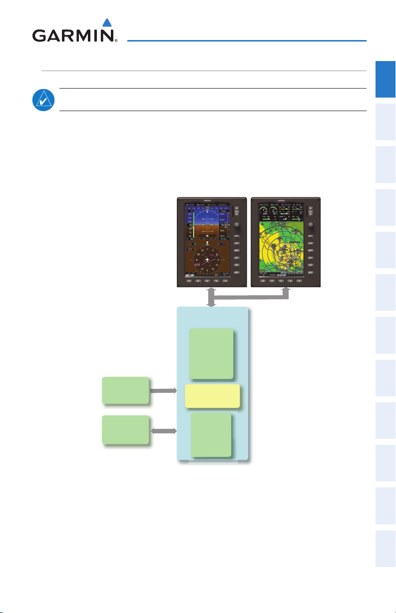
SECTION 1 SYSTEM OVERVIEW
System Overview
Overview
System
The G3X System presents flight instrumentation, position, navigation, communication,
and identification information to the pilot using a single display or multi-display (2 or
3) 7” Wide VGA (800x480) flat-panel color display(s).
1.1 LINE REPLACEABLE UNITS
The system is distributed across the following Line Replaceable Units (LRUs):
• Garmin Display Unit (GDU) 375 (with XM)
Single Display: Split Primary Flight Display (PFD) & Multi Function Display (MFD) –
Multiple Displays: MFD (recommended) –
• GDU 370 (without XM)
Single Display: Split Primary Flight Display (PFD) & Multi Function Display (MFD) –
Multiple Displays: MFD or PFD –
Instruments EIS
Flight
Interface
COM
Navigation
GPS
Planning
Flight
Avoidance
Hazard
Additional
Features
GDU 37X
190-01115-00 Rev. D 1
Garmin G3X Pilot’s Guide
Autopilot Annun/Alerts Appendix Index
Integrated
Page 18
System Overview
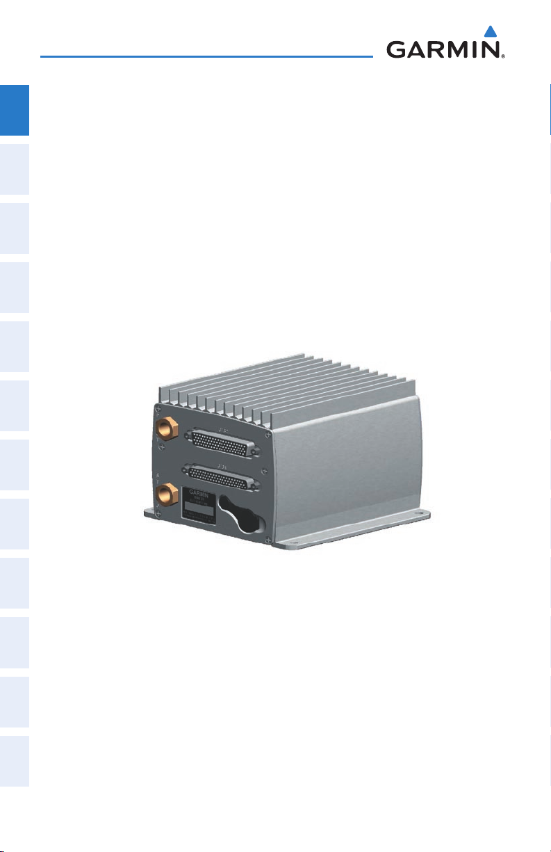
• GSU 73
System
Overview
Flight
InstrumentsEIS
COM
Interface
GPS
Navigation
Flight
Planning
Hazard
Avoidance
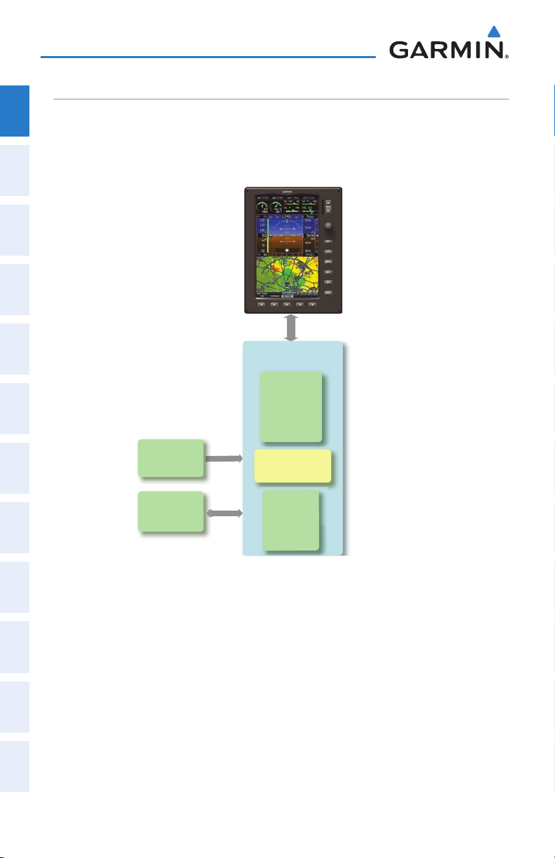
– Garmin Sensor Unit sub-system for the G3X (Air Data Computer (ADC), Engine/
Airframe Unit, and the Attitude and Heading Reference System (AHRS))
ADC: Processes data from the pitot-static system and outside air tem- –
perature (OAT) sensor.
Engine/Airframe Unit: Receives and processes signals from the engine –
and airframe sensors.
AHRS: Provides aircraft attitude and heading information to the PFD. –
The AHRS contains advanced sensors (including accelerometers and rate
sensors) and interfaces with the Magnetometer to obtain magnetic field
information, with the ADC to obtain air data, and with the GDU to obtain
GPS information. AHRS operation is discussed later in this section.
Features
Additional
AutopilotAnnun/AlertsAppendixIndex
Integrated
• GMU 44
2
GSU 73
– Magnetometer: Measures the local magnetic field and sends data to the AHRS
for processing to determine aircraft magnetic heading. This unit receives power
directly from the AHRS and communicates with it via an RS-485 digital interface.
Garmin G3X Pilot’s Guide
190-01115-00 Rev. D
Page 19

GMU 44
System Overview
Overview
System
Instruments EIS
Flight
• GTP 59
– Temperature Probe: Provides raw air temperature data.
GTP 59
Interface
COM
Navigation
GPS
Planning
Flight
Avoidance
Hazard
Additional
Features
Integrated
Autopilot Annun/Alerts Appendix Index
190-01115-00 Rev. D 3
Garmin G3X Pilot’s Guide
Page 20
System Overview
GMU 44
Magnetometer
Heading
GSU 73
Garmin Sensor Unit
GDU 370 or 375 (XM)
AHRS
Attitude
Heading
Rate of Tu rn
Slip/Skid
GTP 59
Temperature
Probe
Air Data
Computer
OAT
Airspeed
Altitude
Ve rtical Speed
Engine/Airframe
Unit
Split PFD/MFD
G3X STANDARD PANEL (SINGLE DISPLAY)
System
In the standard ‘single display’ configuration, the Primary Flight Display (PFD) and
Overview
the Multi Function Display (MFD) share a single GDU.
Flight
InstrumentsEIS
COM
Interface
GPS
Navigation
Flight
Planning
Hazard
Avoidance
Features
Additional
AutopilotAnnun/AlertsAppendixIndex
Integrated
4
Garmin G3X Pilot’s Guide
G3X Standard Panel
(Single Display)
190-01115-00 Rev. D
Page 21
System Overview
GMU 44
Magnetometer
Heading
GSU 73
Garmin Sensor Unit
GDU 370 (PFD)
AHRS
Heading
Attitude
Rate of Tu rn
Slip/Skid
GTP 59
Temperature
Probe
Air Data
Computer
OAT
Airspeed
Altitude
Ve rtical Speed
Engine/Airframe
Unit
GDU 375 (MFD)
G3X UPGRADED PANEL (DUAL-DISPLAY)
NOTE:
With the upgraded ‘dual display’ configuration the left GDU is configured as a PFD
and the right GDU is configured as a MFD. The following is an example of a dual
display system using a GDU 370 and a GDU 375; however, two GDU 370s can be used
in a dual display system if XM is not needed.
The G3X System can be configured with more than two displays.
Overview
System
Instruments EIS
Flight
Interface
COM
Navigation
GPS
Planning
Flight
Avoidance
Hazard
190-01115-00 Rev. D 5
G3X Upgraded Panel
(Dual Display)
Garmin G3X Pilot’s Guide
Additional
Features
Integrated
Autopilot Annun/Alerts Appendix Index
Page 22
System Overview
EXTERNAL NAVIGATORS (OPTIONAL)
System
The G3X can also communicate with the following optional external navigators:
Overview
•SL30Nav/CommTransceiver
Flight
•GNS400/500SeriesUnits
InstrumentsEIS
USING THE G3X WITH AN EXTERNAL GPS NAVIGATOR
WARNING: Do not use the approach information provided by the VFR
COM
Interface
GPS
Navigation
Flight
Planning
Hazard
Avoidance
navigation database residing within the G3X as a means of navigating any
instrument approach. The G3X VFR navigation database is limited to present
only the waypoints for the final approach leg of a published procedure. These
waypoints and associated course line are made available for monitoring
purposes only.
In a configuration which includes one or more external GPS navigators (i.e., GNS
400/500 Series), the G3X displays the selected external GPS Navigator’s flight plan and
guidance information. When using an external GPS navigator with the G3X, changes
to the active flight plan must be entered on the external GPS unit, and the following
G3X functions are disabled:
•Direct-to Key (Section 1.4)
•OBSModeactivationfromtheG3X(i.e.,the‘SetOBSandHold’PFDmenuoption
Features
Additional
is disabled) (Section 2.1)
•VerticalNavigation(Section2.3)
•Flightplanwaypointaddition,deletion,orchange(Section6.1)
AutopilotAnnun/AlertsAppendixIndex
Integrated
•FlightPlanList(LIST)Page(Section6.3)
•Approachselection(ActiveFlightPlan(ACTV)Page)(Section6.6)
6
Garmin G3X Pilot’s Guide
190-01115-00 Rev. D
Page 23

System Overview
Ch a n g i n g t h e na v i g a t i o n So u r C e
Overview
When an external navigator that supports both GPS and VOR/ILS capabilities (i.e.,
GNS 430/530) is selected, the external navigator’s CDI Key is used to switch the G3X
Instruments EIS
HSI between GPS and VOR/ILS navigation.
Se l e C t i o n Be t w e e n Mu l t i p l e na v i g a t o r S
The G3X CDI SRC Softkey (refer to Section 1.7) becomes available when more than
one source of navigation data is configured. The CDI SRC Softkey toggles between
the available navigation sources (e.g., between the internal G3X GPS and external
Interface
SL30 VLOC sources, between an SL30 and a GNS 430, or between two GNS 430s, etc).
Refer to the Flight Instruments section for more information.
Navigation
EXTERNAL GPS NAVIGATOR FAILURE
In the event that all configured external GPS navigators fail, the G3X reverts to it’s
internal VFR GPS for navigation and flight plan modification via the G3X is allowed.
Planning
INTEGRATED AUTOPILOT (OPTIONAL)
Avoidance
The G3X can also communicate with various third-party external autopilot units.
With the Integrated Autopilot configured, the G3X issues pitch and roll steering
commands to the external autopilot unit. Refer to Section 9 (Integrated Autopilot) for
more information.
Features
System
Flight
COM
GPS
Flight
Hazard
Additional
190-01115-00 Rev. D 7
Garmin G3X Pilot’s Guide
Autopilot Annun/Alerts Appendix Index
Integrated
Page 24
System Overview
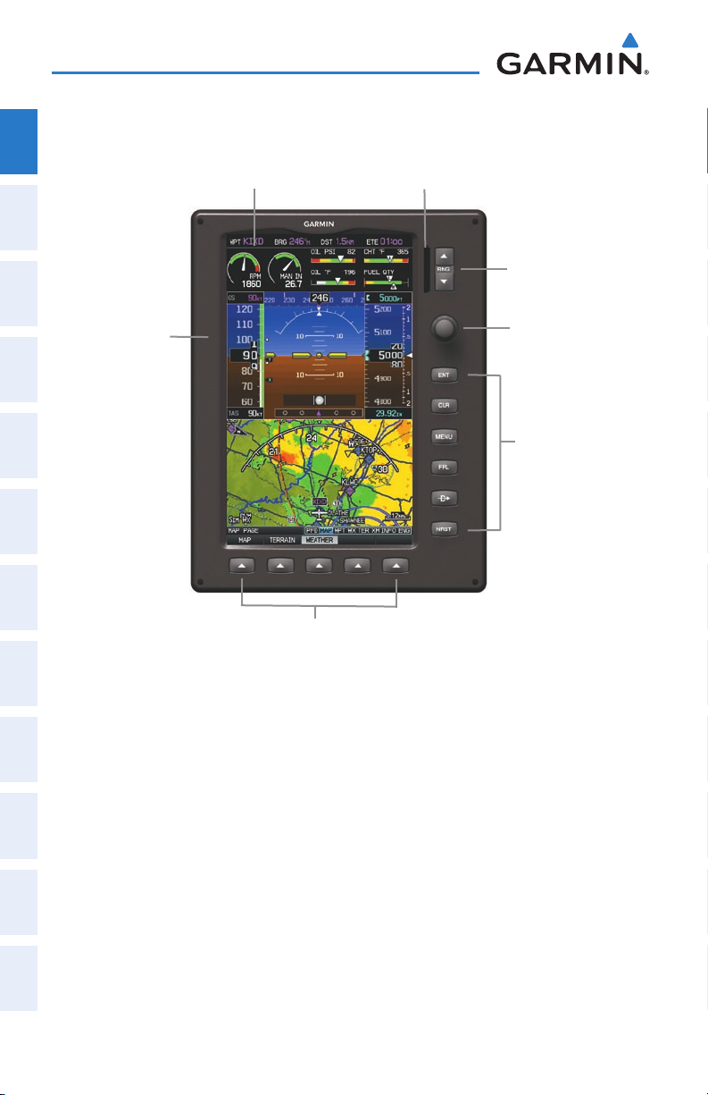
1.2 DISPLAY OVERVIEW
System
Overview
Flight
InstrumentsEIS
7” WVGA (800x480)
Color Display
SD Card Slot
Range (RNG) Key
COM
Interface
GPS
Navigation
Flight
Planning
Hazard
Avoidance
Features
Additional
AutopilotAnnun/AlertsAppendixIndex
Integrated
Display Bezel
FMS Joystick
Hardkeys
Softkeys
Display Overview (Single Display-Map Page)
8
Garmin G3X Pilot’s Guide
190-01115-00 Rev. D
Page 25
1.3 SECURE DIGITAL (SD) CARDS
System Overview
Overview
System
NOTE:
Refer to Appendix C for more information on SD Card use and
databases.
The G3X data card slot uses Secure Digital (SD) cards and is located on the upper
right side of the display bezel(s).
Installing an SD Card:
1)
Insert the SD card in the SD card slot with the card contacts facing the
display (the card should be flush with the face of the bezel).
2)
To eject the card, gently press on the SD card to release the spring latch.
SD Card Slot
Instruments EIS
Flight
Interface
COM
Navigation
GPS
Planning
Flight
Avoidance
Hazard
Additional
Features
Display Bezel SD Card Slot
190-01115-00 Rev. D 9
Garmin G3X Pilot’s Guide
Autopilot Annun/Alerts Appendix Index
Integrated
Page 26
System Overview
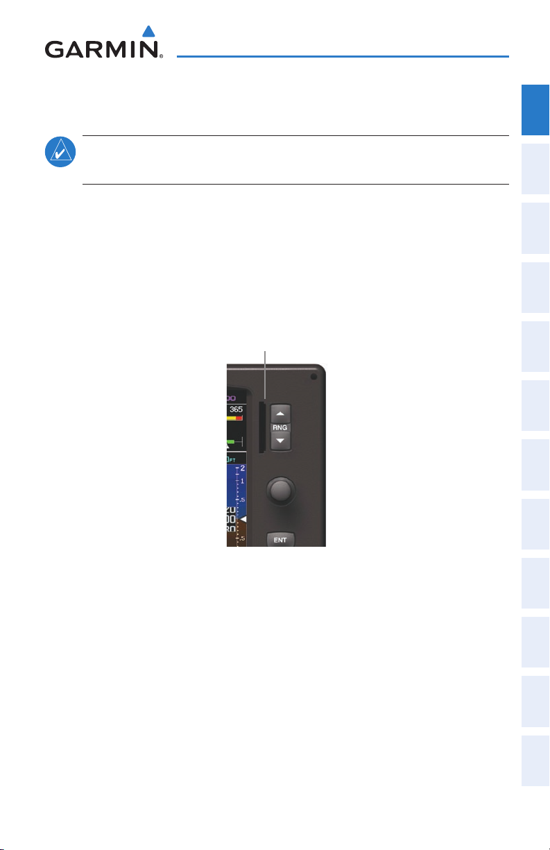
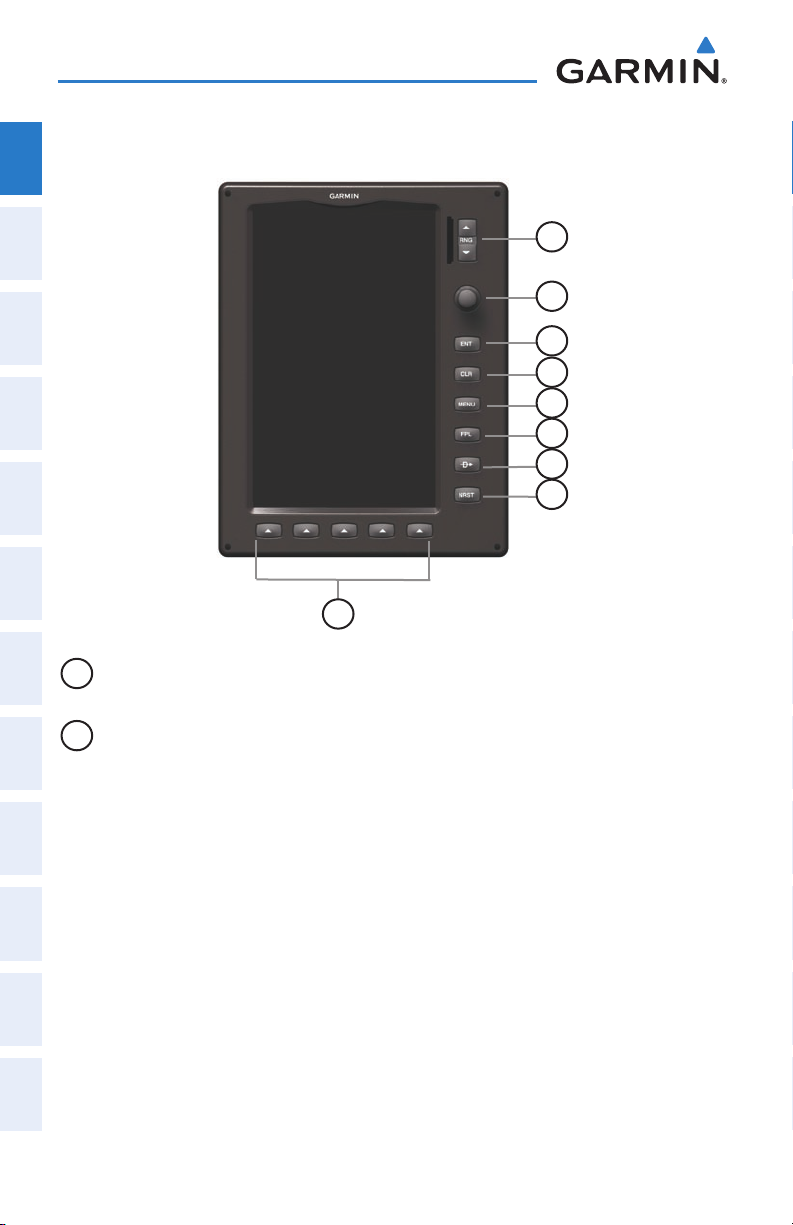
1.4 G3X CONTROLS
System
Overview
Flight
InstrumentsEIS
COM
Interface
GPS
Navigation
Flight
Planning
Hazard
Avoidance
Features
Additional
AutopilotAnnun/AlertsAppendixIndex
Integrated
1
2
3
4
5
6
7
8
9
1
RNG Key Press to increase or decrease the viewing range of the map
Press to increase or decrease the HSI Scale on the PFD or PFD Page
2
FMS
Joystick
Press the FMS Joystick to toggle input focus between user
interaction with the current page and the page navigation bar
Turn the FMS Joystick clockwise to access a drop down menu
within the highlighted field
Turn the FMS Joystick to change the selected value within the
highlighted field
Move the FMS Joystick (up, down, left, or right) to highlight a field
Move the FMS Joystick (up, down, left, right, or diagonally) to move
the map pointer
With the HDG
or HDG/ROLL
Softkey selected, press and hold the
FMS Joystick to sync to the current heading
With the appropriate autopilot mode selected, move the FMS
Joystick (up/down) to adjust the mode reference for Vertical Speed,
Altitude Hold, and Pitch Hold modes, or move the FMS Joystick to
decrease the mode reference for Roll Hold mode.
10
Garmin G3X Pilot’s Guide
190-01115-00 Rev. D
Page 27

System Overview
3
ENT Key Press to confirm menu selection or data entry
Press to acknowledge messages
Press and hold to mark a waypoint
4
CLR Key Press to cancel an entry, revert to the previous value in a data entry
field or remove menus
Press and hold to return to the default page
5
MENU Key Press once to view the Page Menu
Press twice to view the Main Menu
Press a third time to clear the Main Menu
6
FPL Key Press to display the Flight Plan Page
7
Direct-To
Key
8
NRST Key Press to display the Nearest Page for viewing the nearest airports,
Press to activate the Direct-To function, enter a destination
waypoint and establish a direct course to the selected destination
intersections, NDBs, VORs, waypoints, frequencies, and airspaces
9
Softkey
Press to select softkey shown above the bezel key on the display
Selection
Keys
Overview
System
Instruments EIS
Flight
Interface
COM
Navigation
GPS
Planning
Flight
Avoidance
Hazard
Additional
Features
190-01115-00 Rev. D 11
Garmin G3X Pilot’s Guide
Autopilot Annun/Alerts Appendix Index
Integrated
Page 28
System Overview
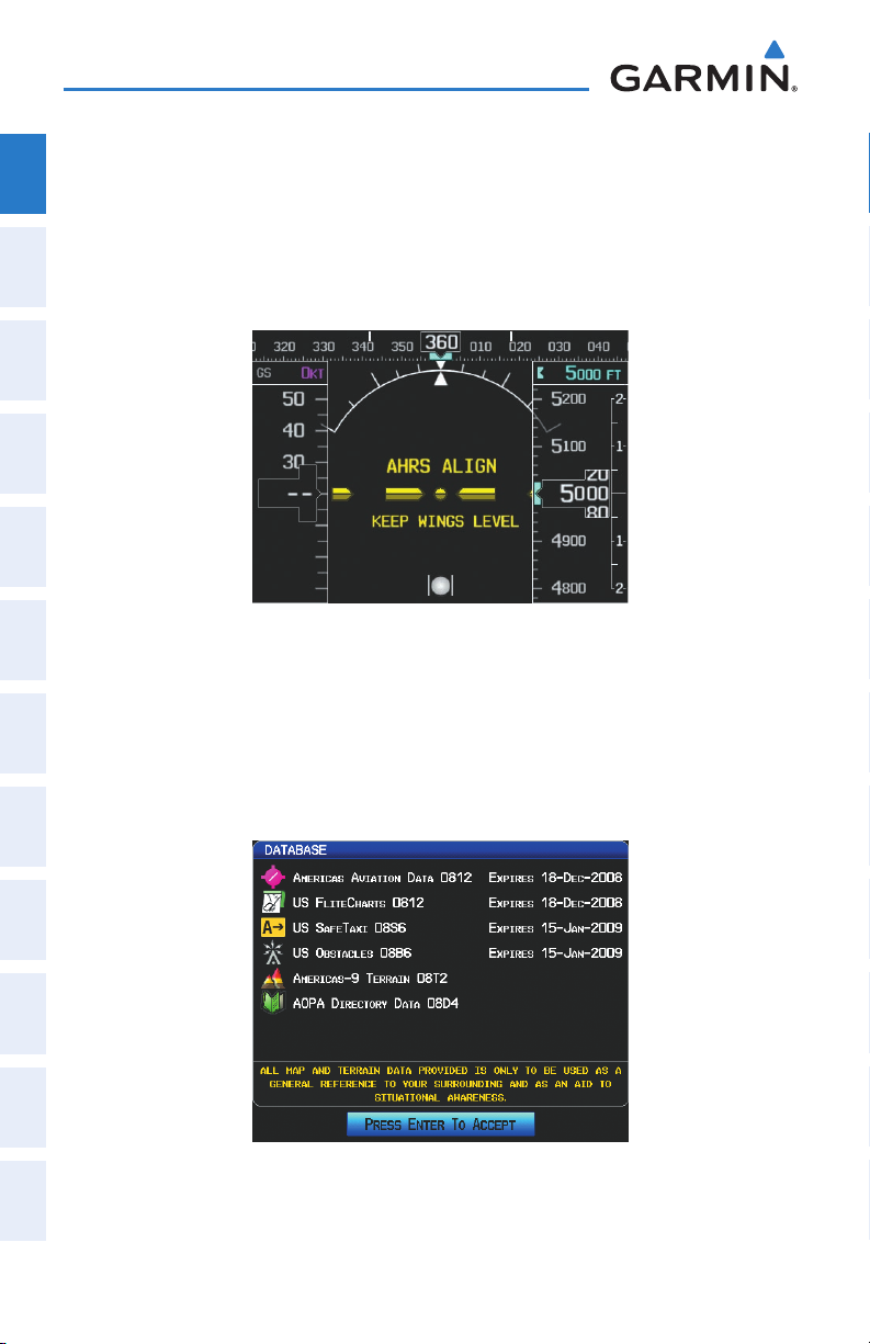
1.5 SYSTEM POWER-UP
System
Overview
During system initialization, the AHRS displays the message ‘AHRS ALIGN, KEEP
WINGS LEVEL’ over the attitude indicator. The AHRS should display valid attitude and
heading fields typically within the first minute of power-up. The AHRS can align itself
Flight
InstrumentsEIS
both while taxiing and during level flight.
COM
Interface
GPS
Navigation
Flight
Planning
System Initialization
Current database information is also displayed during power-up including valid
operating dates, cycle number, and database type. When this information has been
reviewed for currency (to ensure that no databases have expired), the pilot is prompted
Hazard
Avoidance
to continue.
Pressing the ENT Key acknowledges this information.
Features
Additional
AutopilotAnnun/AlertsAppendixIndex
Integrated
Database Information
12
Garmin G3X Pilot’s Guide
190-01115-00 Rev. D
Page 29
1.6 SYSTEM OPERATION
System Overview
Overview
System
This section discusses normal and reversionary G3X display operation, G3X System
Annunciations, and AHRS Operation.
DISPLAY OPERATION
In normal operating mode, the PFD presents graphical flight instrumentation
(attitude, heading, airspeed, altitude, vertical speed), replacing the traditional flight
instrument cluster.
• Single Display
The single display PFD occupies the top portion of the display at all times, and –
a full display PFD can be accessed by navigating to the PFD Page (see Section
1.7, Accessing System Functionality).
The single display MFD occupies the bottom portion of the display. –
Instruments EIS
Flight
Interface
COM
Navigation
GPS
Planning
Flight
Avoidance
Hazard
Additional
Features
G3X Single Display Normal Mode
• Dual Display (Normal Mode)
In normal mode the Dual Display system has a dedicated PFD and MFD. –
190-01115-00 Rev. D 13
Garmin G3X Pilot’s Guide
Autopilot Annun/Alerts Appendix Index
Integrated
Page 30
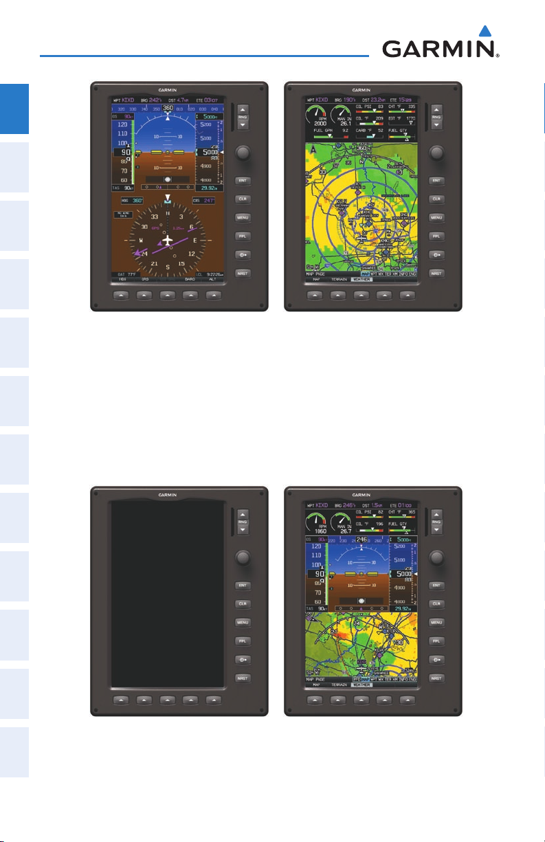
System Overview
System
Overview
Flight
InstrumentsEIS
COM
Interface
G3X Dual Display Normal Mode
GPS
Dual Display (• Reversionary Mode)
Navigation
In the event of a display failure, the G3X System automatically switches to
reversionary (backup) mode. In reversionary mode, all flight information is presented
Flight
Planning
on the remaining display in the same format as the Single Display system.
If a display failure occurs with the GDU 375, the WX and XM Pages will no longer
Hazard
be available since the XM receiver resides in the GDU 375.
Avoidance
Features
Additional
AutopilotAnnun/AlertsAppendixIndex
Integrated
G3X Dual Display Reversionary Mode (Failed PFD)
14
Garmin G3X Pilot’s Guide
190-01115-00 Rev. D
Page 31

System Overview
• Multi-Display (Normal Mode)
In normal mode an example Multi-Display system includes a pilot-side PFD –
(PFD1), MFD, and co-pilot side PFD (PFD2).
PFD1 PFD2MFD
G3X Multi-display Normal Mode (example)
Multi-Display (• Reversionary Mode)
If the system detects a failure in PFD1, the MFD enters reversionary mode. If the MFD
fails, PFD2 enters reversionary mode. A failure of PFD2 is not considered an emergency
and will not cause either of the remaining displays to enter reversionary mode.
Overview
System
Instruments EIS
Flight
Interface
COM
Navigation
GPS
Planning
Flight
Avoidance
Hazard
190-01115-00 Rev. D 15
Garmin G3X Pilot’s Guide
Additional
Features
Integrated
Autopilot Annun/Alerts Appendix Index
Page 32

System Overview
G3X SYSTEM ANNUNCIATIONS
System
When an LRU or an LRU function fails, a large red ‘X’ is typically displayed over
Overview
the instrument(s) or data experiencing the failure (Refer to Appendix F, Abnormal
Operation). Upon G3X power-up, certain instruments remain invalid as equipment
Flight
begins to initialize. All instruments should be operational within one minute of power-
InstrumentsEIS
up. If any instrument remains flagged, and it is not likely an installation related
problem, the G3X should be serviced by a Garmin-authorized repair facility .
COM
Interface
GPS
Navigation
Flight
Planning
PFD Initialization
AHRS OPERATION
Hazard
Avoidance
The Attitude and Heading Reference System (AHRS) performs attitude, heading, and
vertical acceleration calculations for the G3X System, utilizing GPS, magnetometer,
Features
and air data in addition to information from its internal sensors. Attitude and heading
Additional
information are updated on the PFD while the AHRS receives appropriate combinations
of information from the external sensor inputs.
AutopilotAnnun/AlertsAppendixIndex
Integrated
16
Garmin G3X Pilot’s Guide
190-01115-00 Rev. D
Page 33

AHRS Operation
Attitude/Heading Invalid
AHRS
no-GPS
Mode
AHRS Normal
Operation
AHRS no-
Mag Mode
AHRS no-Mag/
no-Air Mode
Heading Invalid
available
available
unavailable
unavailable
available
unavailable
unavailable
available
e
Air Data
e
Magnetometer Data
unavailable
available
l
GPS Data
l
e
Magnetometer Data
e
un
Air Data
System Overview
Overview
System
Instruments EIS
Flight
Interface
COM
Navigation
GPS
Planning
Flight
Avoidance
Hazard
Loss of GPS, magnetometer, or air data inputs is communicated to the pilot by
message advisory alerts. Any failure of the internal AHRS inertial sensors results in loss
of attitude and heading information (indicated by red ‘X’ flags over the corresponding
flight instruments).
If GPS input fails, the AHRS can continue to provide attitude and heading information
to the PFD as long as magnetometer and airspeed data are available and valid.
If the magnetometer input fails, the AHRS continues to output valid attitude
information; however, the heading output on the PFD Page is flagged as invalid with
a red ‘X’.
Failure of the air data input has no effect on the AHRS output while AHRS is receiving
valid GPS information. Invalid/unavailable airspeed data in addition to GPS failure
results in loss of all attitude and heading information. Likewise, loss of magnetometer
(heading) data, in combination with loss of GPS data results in a loss of all attitude
and heading information.
190-01115-00 Rev. D 17
Garmin G3X Pilot’s Guide
Additional
Features
Integrated
Autopilot Annun/Alerts Appendix Index
Page 34

System Overview
1.7 ACCESSING SYSTEM FUNCTIONALITY
System
Overview
MENUS
Flight
InstrumentsEIS
COM
Interface
GPS
Navigation
Flight
Planning
Hazard
Avoidance
Features
Additional
NOTE:
Flight Log and Track Log must be accessed from the MFD in a Multiple
Display system.
The G3X has a dedicated MENU Key that when pressed once displays a contextsensitive list of options for the page (Page Menu) or the PFD (dual display), and when
pressed twice displays the Main Menu.
The Page Menu allows the user to access additional features or make setting changes
which specifically relate to the currently displayed window/page. The menu will display
‘No Options’ when there are no options for the window/page selected.
Navigating the page menu:
1)
Press the MENU Key once to display the Page Menu.
2)
Turn or move the FMS Joystick to scroll through a list of available options
(a scroll bar always appears to the right of the window/box when the
option list is longer than the window/box).
3)
Press the ENT Key to select the desired option.
4)
Press the FMS Joystick, CLR Key, or press the MENU Key twice to remove
the menu and cancel the operation.
AutopilotAnnun/AlertsAppendixIndex
Integrated
Page Menu (No Options)
TER Page Menu
Navigating the main menu:
1)
Press the MENU Key twice to display the Main Menu.
2)
Turn or move the FMS Joystick to scroll through a list of available options
(a scroll bar always appears to the right of the window/box when the
option list is longer than the window/box).
18
Garmin G3X Pilot’s Guide
190-01115-00 Rev. D
Page 35

System Overview
3)
Press the ENT Key to select the desired option.
4)
Press the FMS Joystick, CLR Key, EXIT Softkey, or press the MENU Key to
remove the menu and cancel the operation.
Overview
System
Instruments EIS
Flight
Interface
COM
Main Menu (Single Display)
Main Menu (Dual Display - MFD)Main Menu (Dual Display - PFD)
DATA ENTRY
The FMS Joystick can be used for directly entering alphanumeric data into the G3X.
In some instances, such as when entering an identifier, the G3X tries to predict the
desired identifier based on the characters being entered. In this case, if the desired
identifier appears, use the ENT Key to confirm the entry without entering the rest of
the identifier manually. This can save the pilot from having to enter all the characters
of the identifier.
Besides character-by-character data entry, the system also provides a shortcut
for entering waypoint identifiers. When the cursor is on a field awaiting entry of a
waypoint identifier, turning the FMS Joystick counter-clockwise accesses a menu
with three different lists of identifiers for quick selections: recent waypoints (RECENT
WPTS), nearest airports (NRST APTS), and flight plan waypoints (FPL WPTS). The G3X
automatically fills in the identifier, facility, and city fields with the information for the
selected waypoint.
Navigation
GPS
Planning
Flight
Avoidance
Hazard
Additional
Features
Integrated
Autopilot Annun/Alerts Appendix Index
190-01115-00 Rev. D 19
Garmin G3X Pilot’s Guide
Page 36

System Overview
Using the FMS Joystick to enter data:
1)
System
Overview
Flight
InstrumentsEIS
Press the FMS Joystick to activate the cursor.
2)
Move the FMS Joystick to highlight the desired field.
3)
Begin entering data.
a)
To quickly enter a waypoint identifier, turn the FMS Joystick counterclockwise to display a list of recent waypoints (RECENT WPTS), nearest
airports (NRST APTS) or flight plan waypoints (FPL WPTS).
b)
Move the FMS Joystick to highlight the desired waypoint from the list
and press the ENT Key.
COM
Interface
GPS
Navigation
Flight
Planning
Hazard
Additional
Integrated
Avoidance
Features
AutopilotAnnun/AlertsAppendixIndex
20
Or
a)
b)
Waypoint Entry (Waypoint Page - Single Display)
:
Turn the FMS Joystick clockwise to select a character for the first
placeholder.
Data Entry
Turning the FMS Joystick clockwise scrolls through the alphabet (where
appropriate) toward the letter Z, starting in the middle at K (US only),
and the digits zero through nine. Turning the FMS Joystick counterclockwise scrolls in the opposite direction.
Use the FMS Joystick to move the cursor to the next placeholder in the
field.
Garmin G3X Pilot’s Guide
190-01115-00 Rev. D
Page 37

c)
d)
Or:
PAGES
System Overview
Repeat, turning the FMS Joystick to select a character and then moving
the FMS Joystick to move the cursor, until the fields are complete.
Press the ENT Key to confirm entry.
Press the FMS Joystick or the CLR Key to cancel data entry (the field
reverts back to its previous information).
Overview
System
Instruments EIS
Flight
The Main Pages, Flight Plan Pages, and Nearest Pages are linked together in a series
that you can cycle through using the FMS Joystick. A page navigation bar is displayed
on the lower portion of the display, directly above the softkey bar. The right side of the
page navigation bar shows a list of abbreviated names for each of the pages, and the
left side shows the name of the current page.
Press the FMS Joystick to toggle input focus between the Page Navigation Bar and
interaction with the current page (i.e., turning the page cursor on/off). When the Page
Navigation Bar is highlighted blue, the user can cycle through the pages using the
FMS Joystick. If the Page Navigation Bar is not highlighted blue, the user can interact
with the current page (if available).
The Single Display PFD occupies the top portion of the display while the selected
page occupies the bottom portion of the display.
Selected Page
Input Focus on Page Navigation Bar
Active Page Title
(Page Cursor Off)
Input Focus on Current Page
(Page Cursor On)
Interface
COM
Navigation
GPS
Planning
Flight
Avoidance
Hazard
Additional
Features
Integrated
Autopilot Annun/Alerts Appendix Index
Page Navigation (Single Display)
190-01115-00 Rev. D 21
Garmin G3X Pilot’s Guide
Page 38

System Overview
MAIN PAGES
System
Overview
NOTE:
Flight
InstrumentsEIS
There are up to eight Main Pages (seven for the dual display) that can be navigated
using the FMS Joystick.
Selecting a main page using the FMS Joystick:
1)
COM
Interface
2)
GPS
Navigation
Flight
Planning
In the Dual Display configuration, the Main Pages are only available
from the MFD.
If necessary, press the FMS Joystick to begin interaction with the Page
Navigation Bar.
Turn the FMS Joystick until the desired page is selected (PFD (single
display), MAP, WPT, WX, TER, XM, INFO, ENG).
Hazard
Additional
Integrated
Avoidance
Features
AutopilotAnnun/AlertsAppendixIndex
22
Garmin G3X Pilot’s Guide
190-01115-00 Rev. D
Page 39

System Overview
•
Main Pages
PFD Page (PFD) (single display)
Map Page (MAP) XM Audio Page (XM) (optional)
Waypoint Page (WPT) Info Page (INFO)
Weather Page (WX) (optional)
Terrain Page (TER)
Engine Page (ENG)
Overview
System
Instruments EIS
Flight
Interface
COM
Navigation
GPS
Planning
Flight
Avoidance
Hazard
Main Pages (Single Display)
190-01115-00 Rev. D 23
Garmin G3X Pilot’s Guide
Additional
Features
Integrated
Autopilot Annun/Alerts Appendix Index
Page 40

System Overview
FLIGHT PLAN AND NEAREST PAGES
System
Overview
NOTE:
external GPS navigator is configured.
Flight
InstrumentsEIS
There are also several pages which are selected first by pressing the FPL Key or
NRST Key.
Selecting the FPL or NRST pages:
1)
Press the FPL or NRST Key.
2)
COM
Interface
GPS
Navigation
Turn the FMS Joystick until the desired page is selected.
3)
To return to the Main Pages, press the EXIT Softkey.
The Nearest Pages contain the following information.
APT (Airport)• —identifier, bearing, distance, length of the longest runway, and
common traffic advisory (CTAF) or tower frequency.
The Flight Plan List Page and the VNAV Page are not available when an
Flight
Hazard
Additional
Integrated
WX (Airport Weather) (GDU 375 Only)• —identifier, bearing, distance, METAR text,
Planning
and ATIS, AWOS, or ASOS frequency.
VOR (VHF Omnidirectional Radio Beacon)• —identifier, facility type (symbol),
bearing, distance, and frequency.
Avoidance
NDB (Non Directional Beacons)• —identifier, facility, type (symbol), bearing,
distance, and frequency.
Features
INT (Intersection)• —identifier, bearing, and distance.
VRP (Visual Reporting Point) (Atlantic)• —identifier, bearing, and distance.
AutopilotAnnun/AlertsAppendixIndex
USR (User Waypoints)• —name, bearing, and distance.
CTY (City)• —name, bearing, and distance.
ATC (Air Route Traffic Control Center)• —bearing, distance, and frequency.
FSS (Flight Service Station)• —name, bearing, distance, frequency, and VOR (if
applicable).
ASPC (Airspace)• —name, time to entry (when applicable), and status.
24
Garmin G3X Pilot’s Guide
190-01115-00 Rev. D
Page 41

System Overview
•
Nearest Pages (NRST)
Nearest Airports (APT) Nearest User Waypoints (USR)
Nearest Airport Weather (WX) (GDU 375) Nearest Cities (CTY)
Nearest VORs (VOR) Nearest ARTCC (ATC)
Nearest NDBs (NDB) Nearest FSS (FSS)
Nearest Intersections (INT) Nearest Airspace (ASPC)
Visual Reporting Point (VRP) (Atlantic)
Overview
System
Instruments EIS
Flight
Interface
COM
Navigation
GPS
Planning
Flight
Avoidance
Hazard
Nearest Pages (Single Display)
190-01115-00 Rev. D 25
Garmin G3X Pilot’s Guide
Additional
Features
Integrated
Autopilot Annun/Alerts Appendix Index
Page 42

System Overview
•Flight Planning Pages (FPL)
System
Overview
Flight
InstrumentsEIS
COM
Interface
GPS
Navigation
Active Flight Plan (ACTV) Vertical Navigation (VNAV)
Flight Plan List (LIST)
Flight
Planning
Flight Planning Pages (Single Display)
SOFTKEY FUNCTION
Hazard
The softkeys are located along the bottom of the display(s). The softkeys shown
Avoidance
depend on the softkey level or page being displayed. The bezel keys below the softkeys
can be used to select the appropriate softkey. When a softkey is selected, its color
Features
undergoes a momentary change to black text on blue background then automatically
Additional
switches to black text on gray background and remains this way until it is turned off,
at which time it reverts to white text on black background. When a softkey function is
AutopilotAnnun/AlertsAppendixIndex
Integrated
disabled, the softkey label is subdued (dimmed).
Softkey
On
Softkey Names
(Displayed)
Bezel Mounted
Softkeys (Press)
Softkeys (WPT Page)
26
Garmin G3X Pilot’s Guide
190-01115-00 Rev. D
Page 43

System Overview
HDG
CRS CDI SRC
BARO
ALT
HDG/ROLL
CRS CDI SRC
BARO
ALT/PTCH
PFD PAGE (SINGLE DISPLAY) & PFD (DUAL DISPLAY)
SOFTKEYS
HDG Allows the pilot to adjust the heading bug
CRS/OBS Allows the pilot to adjust the course in OBS mode
CDI SRC Toggles between available NAV sources (when configured)
BARO Allows the pilot to adjust the barometric pressure setting
ALT Allows the pilot to adjust the selected altitude
PFD PAGE (SINGLE DISPLAY) & PFD (DUAL DISPLAY)
SOFTKEYS (INTEGRATED AUTOPILOT CONFIGURED)
HDG/ROLL Allows the pilot to adjust the heading bug and displays lateral
mode softkeys
CRS/OBS Allows the pilot to adjust the course in OBS mode
CDI SRC Toggles between available NAV sources (when configured)
BARO Allows the pilot to adjust the barometric pressure setting
ALT/PTCH Allows the pilot to adjust the selected altitude and displays
vertical mode softkeys
Overview
System
Instruments EIS
Flight
Interface
COM
Navigation
GPS
Planning
Flight
Avoidance
Hazard
Additional
Features
Integrated
Autopilot Annun/Alerts Appendix Index
190-01115-00 Rev. D 27
Garmin G3X Pilot’s Guide
Page 44

System Overview
HDG/ROLL
HDG/ROLL
ALT/PTCH
AP HDG AP NAV
ALT/PTCH
AP ALTAP VSAP VNAVHDG/ROLL
ALT/PTCH
(AP APPR)
System
Overview
Flight
InstrumentsEIS
COM
Interface
GPS
Navigation
HDG/ROLL Softkey selected
HDG/ROLL Initial press allows the pilot to adjust the heading bug
Flight
Planning
AP HDG Selects/deselects heading mode
Hazard
AP NAV Selects/deselects navigation mode
Avoidance
ALT/PTCH Initial press allows the pilot to adjust the selected altitude
Features
Additional
ALT/PTCH Softkey selected
and displays lateral mode softkeys; subsequent press
returns to top-level softkeys
and displays the vertical mode softkeys; subsequent
press returns to top-level softkeys
AutopilotAnnun/AlertsAppendixIndex
Integrated
HDG/ROLL Initial press allows the pilot to adjust the heading bug
AP VNAV
and displays lateral mode softkeys; subsequent press
returns to top-level softkeys
Selects/deselects altitude hold mode
or
AP APPR
AP VS Selects/deselects vertical speed mode
Selects/deselects approach mode
AP ALT Selects/deselects altitude hold mode
ALT/PTCH Initial press allows the pilot to adjust the selected altitude
28
and displays the vertical mode softkeys; subsequent
press returns to top-level softkeys
Garmin G3X Pilot’s Guide
190-01115-00 Rev. D
Page 45

System Overview
MAP
TERRAIN
WEATHER
MAP
VFR MAP
BACK
IFR MAP TOPO
BACK
Press the BACK Softkey to
return to the top-level softkeys.
SAT VIEW
HIGH AWYLOW AWYIFR MAPVFR MAP
MAP PAGE SOFTKEYS
MAP Enables second-level Map Page softkeys
TERRAIN Displays/removes terrain awareness information
WEATHER Displays/removes weather information
Overview
System
Instruments EIS
Flight
Interface
COM
Navigation
GPS
Planning
Flight
Avoidance
Hazard
VFR MAP Softkey selected
IFR MAP Displays IFR map information and softkeys
TOPO Displays/removes topographical terrain shading
SAT VIEW Displays/removes satellite imagery (above 20nm scale)
BACK Returns to top-level softkeys
IFR MAP Softkey selected
VFR MAP Displays VFR map information and softkeys
LOW AWY Low Altitude (Victor) Airways displayed
HIGH AWY High Altitude Airways (Jet Routes) displayed
BACK Returns to top-level softkeys
190-01115-00 Rev. D 29
Garmin G3X Pilot’s Guide
Additional
Features
Integrated
Autopilot Annun/Alerts Appendix Index
Page 46

System Overview
INFO
RUNWAY CHART AOPA WEATHER
INFO
CHART AOPA WEATHER
PAN MAP
ANIMATE
LEGEND INFO
WAYPOINT PAGE SOFTKEYS
System
Overview
Flight
InstrumentsEIS
COM
Interface
GPS
Navigation
Flight
Planning
Hazard
Avoidance
Features
Additional
Waypoint (WPT) Page Softkeys
(Single Display)
Waypoint (WPT) Page Softkeys
(Dual Display)
INFO Displays waypoint information
RUNWAY Displays runway information (Single Display)
CHART Displays optional FliteCharts
AOPA Displays AOPA information
WEATHER Displays METAR and TAF text (optional)
WEATHER PAGE SOFTKEYS (OPTIONAL)
AutopilotAnnun/AlertsAppendixIndex
Integrated
30
PAN MAP Activates the map pointer for panning the map
ANIMATE Animates NEXRAD Radar and Satellite Mosaic weather
INFO Displays XM Information
LEGEND Displays weather legends
Garmin G3X Pilot’s Guide
190-01115-00 Rev. D
Page 47

System Overview
MAP
PROFILE
INFO
CHANNEL
VOLUME
CATEGORY
FAVORITE
VOL +
BACK VOL -
MUTE
VOLUME
Press the BACK Softkey to
return to the top-level softkeys.
TERRAIN PAGE SOFTKEYS (SINGLE DISPLAY)
MAP Displays the Terrain Page Map View
PROFILE Displays the Terrain Page Profile View.
XM AUDIO PAGE SOFTKEYS (OPTIONAL)
INFO Displays XM Information
CATEGORY Highlights the Category field
CHANNEL Highlights the Channels field
FAVORITE Displays a list of favorite channels
VOLUME Enables second-level VOLUME softkeys
Press and hold to toggle Mute on/off.
Overview
System
Instruments EIS
Flight
Interface
COM
Navigation
GPS
Planning
Flight
Avoidance
Hazard
VOL - Decreases XM audio volume
VOL + Increases XM audio volume
MUTE Toggles XM audio on/off
BACK Returns to top-level softkeys
190-01115-00 Rev. D 31
Garmin G3X Pilot’s Guide
Additional
Features
Integrated
Autopilot Annun/Alerts Appendix Index
Page 48

System Overview
MESSAGES
MAIN LEAN FUEL
(optional)
(optional)
(optional)
AUX, ELEC,
TRIM
(optional)
INFO PAGE SOFTKEY
System
Overview
Flight
InstrumentsEIS
MESSAGES Displays system status messages
ENG PAGE SOFTKEYS (EXAMPLE CONFIGURATION)
COM
Interface
NOTE:
configuration. Refer to the G3X Installation Manual for information on
The Engine (ENG) Page softkeys displayed are dependant on the
configuring the Engine Page.
If the Engine Page information configured exceeds one page, additional engine
GPS
Navigation
gauges may be distributed among the 1st, 2nd, and 3rd softkeys as required.
Flight
Planning
Hazard
Additional
MAIN Displays main engine gauges (optional)
Avoidance
AUX, AUX1, AUX2, ELEC,
TRIM, TEMPS
Features
LEAN Activates/deactivates Lean Assist (optional)
Displays additional engine gauges as required
(optional)
FUEL Displays Fuel Calculator (optional)
AutopilotAnnun/AlertsAppendixIndex
Integrated
32
Garmin G3X Pilot’s Guide
190-01115-00 Rev. D
Page 49

System Overview
XX GAL
XX GAL XX GAL
FUEL
FUEL
RESET
(optional) (optional)
(optional)
RESET Resets fuel used to zero and fuel remaining to full
tanks
XX GAL Sets fuel remaining to the full tank quantity where XX
is the airframe specific full fuel quantity
XX GAL Sets fuel remaining to a partial tank quantity (i.e., filler
neck tab) where XX is an airframe specific partial
fuel quantity (optional)
XX GAL Sets fuel remaining to a partial tank quantity (i.e., filler
neck tab) where XX is an airframe specific partial
fuel quantity (optional)
FUEL Returns to top-level softkeys
Overview
System
Instruments EIS
Flight
Interface
COM
Navigation
GPS
Planning
Flight
Avoidance
Hazard
Additional
Features
Various softkeys revert to the previous level after 45 seconds of inactivity (e.g.,
PAN MAP, VOLUME, etc), other softkeys require manual de-selection (e.g., TERRAIN,
WEATHER, PANEL, etc.).
190-01115-00 Rev. D 33
Garmin G3X Pilot’s Guide
Autopilot Annun/Alerts Appendix Index
Integrated
Page 50

System Overview
1.8 ACCESSING THE INFORMATION (INFO) PAGE
System
Overview
VIEWING GPS RECEIVER STATUS
Internal system checking is performed to ensure the GPS receiver is providing
Flight
InstrumentsEIS
accurate data to the GDU(s).
The Dual Display System can be configured to share GPS information (refer to the
G3X Installation Manual for configuration information). For example, a GDU can be
configured to share its GPS position, velocity, and time data with another GDU. If a
GDU is not using its own GPS receiver, the name of the GDU providing the data (i.e.,
COM
Interface
‘3D GPS Location (PFD)’ or ‘3D GPS Location (MFD)’) is displayed following the GPS
Status text on the INFO Page.
GPS
The GPS Status will display one of the following conditions:
Navigation
•Autolocate—Receiver is looking for any satellite whose almanac has been
collected, which can take up to 5 minutes
Flight
Planning
•SearchingtheSky—Receiverislookingforsatellites
•Acquiring Satellites—Receiver islooking forandcollecting datafrom satellites
Hazard
visible at its last known or initialized location, but has not acquired a fix
Avoidance
•2D GPS Location—At least three satellites have been acquired and a two-
dimensional location fix has been calculated. “2D Differential” appears when
Features
Additional
you are receiving DGPS corrections in 2D mode
•3D GPS Location—At least four satellites have been acquired and a three-
Integrated
receiving DGPS corrections in 3D mode
dimensional fix has been calculated. “3D Differential” appears when you are
AutopilotAnnun/AlertsAppendixIndex
•LostSatelliteReception—thereceiverisnolongertrackingenoughsatellitesfora
2D or 3D fix
GPS Status, Position, and Data Fields (Dual Display only) can be accessed from the
Information Page.
34
Garmin G3X Pilot’s Guide
190-01115-00 Rev. D
Page 51

System Overview
Overview
System
Instruments EIS
Flight
INFO Page (Single Display)
Data Fields
Constellation
Diagram
PRN Number
Receiver Status
Signal Strength Bars
45° Above
Horizon
Horizon
Reference Waypoint
INFO Page (Dual Display - MFD)
Viewing GPS receiver status information:
1)
If necessary press the FMS Joystick to begin interaction with the Navigation
Bar.
Interface
COM
Navigation
GPS
Planning
Flight
Avoidance
Hazard
Additional
Features
Integrated
Autopilot Annun/Alerts Appendix Index
2)
Turn the
190-01115-00 Rev. D 35
FMS Joystick
until the Info Page is selected.
Garmin G3X Pilot’s Guide
Page 52

System Overview
NEW LOCATION
System
The ‘New Location’ menu option on the INFO Page is used when the GPS Receiver
Overview
is having trouble finding the satellites it expects to be there.
Flight
Entering a new location:
InstrumentsEIS
1)
From the
INFO
Page, while the unit is searching for satellites, press the
MENU Key.
2)
COM
Interface
GPS
Navigation
With ‘New Location’ menu option highlighted, press the
3)
Move the
the
4)
After selecting your approximate position using the map pointer or entering
an identifier, press the
5)
The GPS Receiver will begin a new search based on the location entered.
ENT
FMS
Joystick to highlight ‘Use Map’ or ‘Use Identifier’, and press
Key.
ENT
Key.
INFO
Key.
ACQUIRING SATELLITES
When the receiver is in the process of acquiring enough satellite signals for
Flight
Planning
navigation, the receiver uses satellite orbital data (collected continuously from the
satellites) and last known position to determine the satellites that should be in view.
“Acquiring Satellites” is indicated as the solution until a sufficient number of satellites
Hazard
Avoidance
have been acquired for computing a solution.
When the receiver is in the process of acquiring a 3D differential GPS solution, “3D
Features
Additional
GPS Location” is indicated as the solution until the 3D differential fix has finished
acquisition.
SATELLITE INFORMATION
AutopilotAnnun/AlertsAppendixIndex
Integrated
Satellites currently in view are shown at their respective positions on a satellite
constellation diagram. The outer circle of the constellation diagram represents the
horizon, the inner circle represents 45° above the horizon, and the center point shows
the position directly overhead. Each satellite is represented by a square containing the
Pseudo-Random Noise (PRN) number (i.e., satellite identification number).
36
Garmin G3X Pilot’s Guide
190-01115-00 Rev. D
Page 53

System Overview
The INFO Page can be helpful in troubleshooting weak (or missing) signal levels
due to poor satellite coverage or installation problems. As the GPS receiver locks
onto satellites, a signal strength bar is displayed for each satellite in view, with the
appropriate satellite PRN number (01-32 or 33-64 for WAAS) below each bar. The
progress of satellite acquisition is shown in three stages, as indicated by signal bar
appearance:
- No bar—Receiver is looking for the indicated satellite
- Gray bar—Receiver has collected the necessary data and the satellite signal can
be used
- Green bar—Satellite is being used for the GPS solution
POSITION
The Position box on the INFO Page displays latitude, longitude, accuracy (in feet),
reference waypoint, type, distance, direction, and bearing. The reference waypoint is
designed to display the current position in relation to a prominent landmark. The pilot
can change the reference waypoint ‘Nearest Type’ using the ‘Change Nearest Type’
page menu option. By default the Nearest Type is set to ‘Automatic’, which will display
the nearest large airport, enroute VOR, or city (in that order).
Overview
System
Instruments EIS
Flight
Interface
COM
Navigation
GPS
Planning
Flight
Avoidance
Hazard
Reference
Waypoint
Position Information (INFO Page - Single Display)
Changing the Nearest Type:
1)
From the Info Page press the MENU Key.
2)
Turn or move the FMS Joystick to highlight ‘Change Nearest Type’ and
press the ENT Key.
3)
Move the FMS Joystick to highlight the desired nearest type option
(Automatic, Airport, VOR, NDB, Intersection, City, Waypoint), and press the
ENT Key.
190-01115-00 Rev. D 37
Garmin G3X Pilot’s Guide
Additional
Features
Integrated
Autopilot Annun/Alerts Appendix Index
Page 54

System Overview
System
Overview
Flight
InstrumentsEIS
COM
Interface
INFO Page Menu Nearest Type Menu
SHOW/HIDE LAT/LON ON THE INFO PAGE
GPS
Navigation
If the Location Format selected on the Position Setup Page (refer to Appendix D,
Map Datum and Location Formats) is not set to a Lat/Lon format, a new menu option
‘Show/Hide Lat/Lon’ will appear on the INFO Page. Selecting ‘Show Lat/Lon’ allows
Flight
Planning
simultaneous display of the current position in both the selected location format as
well as Lat/Lon format.
Hazard
Avoidance
DATA FIELDS AND LAYOUT (DUAL DISPLAY - MFD)
The page layout and Data Fields of the Dual Display Info Page can be independently
configured by the user. Refer to the Annunciations and Alerts Section for a list of
Features
Additional
available Info Page Data Field options.
Changing the Info Page Data Fields (Dual Display):
AutopilotAnnun/AlertsAppendixIndex
Integrated
1)
From the Info Page press the MENU Key.
2)
Turn or move the FMS Joystick to highlight ‘Change Data Fields’ and press
the ENT Key. The cursor is displayed on the first Data Field.
3)
Move the FMS Joystick to highlight the desired Data Field.
4)
Turn the FMS Joystick to access a list of available Data Field options.
5)
Turn or move the FMS Joystick to highlight the desired Data Field, and
press the ENT Key.
38
Garmin G3X Pilot’s Guide
190-01115-00 Rev. D
Page 55

INFO Page Menu Data Field Options
Changing the Info Page layout:
1)
From the Info Page press the MENU Key.
2)
Turn or move the FMS Joystick to highlight ‘Select Page Layout’ and press
the ENT Key.
3)
Move the FMS Joystick to highlight the desired page layout option (1 Row,
2 Rows, 3 Rows), and press the ENT Key.
1.9 SYSTEM SETTINGS
System Overview
Overview
System
Instruments EIS
Flight
Interface
COM
Navigation
GPS
Planning
Flight
Avoidance
Hazard
The System Setup option in the Main Menu allows management of the following
system parameters:
•DataBarFields
•Display
•Sound
•Units
System Setup Menu (Single Display)
190-01115-00 Rev. D 39
Garmin G3X Pilot’s Guide
•Date&Time
•Position
•Alarms
Additional
Features
Integrated
Autopilot Annun/Alerts Appendix Index
Page 56

System Overview
Restoring system setting defaults:
1)
System
Overview
Press the MENU Key twice to display the Main Menu.
2)
Turn or move the FMS Joystick to highlight ‘System Setup...’ and press the
ENT Key.
Flight
3)
InstrumentsEIS
Turn or move the FMS Joystick to highlight the desired menu option (Data
Bar Fields, Display, Date & Time, Position, or Alarms), and press the ENT
Key.
4)
Press the MENU Key.
5)
With the ‘Restore Default’ highlighted press the ENT Key.
COM
Interface
GPS
Navigation
DATA BAR FIELDS
Flight
Planning
Restore Default Window
The content of the four data bar fields are independently configured by the user. The
Dual Display MFD and PFD Data Bar Fields are independently configured from each
display.
Hazard
Avoidance
Data Bar
Features
Additional
Data Bar (PFD Page - Single Display)
AutopilotAnnun/AlertsAppendixIndex
Integrated
Data Bar
Fields
Data Bar Setup Page (Single Display)
40
Garmin G3X Pilot’s Guide
190-01115-00 Rev. D
Page 57

System Overview
By default, the Single Display and the Dual Display PFD data bar fields are set to
display Next Waypoint (WPT), Bearing to Waypoint (BRG), Distance to Waypoint (DIS),
and Estimated Time Enroute (ETE). The Dual Display MFD data bar fields default to
Ground Speed (GS), Ground Track (TRK), Minimum Safe Altitude (MSA), and Vertical
Speed Required (VSR). These four data fields can be changed to display any of the
Data Bar Field Options. Refer to the Annunciations and Alerts Section for a list of
available Data Bar Field options.
Changing the information shown in the data bar fields:
1)
Press the MENU Key twice to display the Main Menu.
2)
Turn or move the FMS Joystick to highlight ‘System Setup...’ and press the
ENT Key.
3)
With ‘Data Bar Fields’ highlighted, press the ENT Key.
4)
Move the FMS Joystick to highlight the desired ‘Field’.
5)
Turn the FMS Joystick to access the list of options, then turn or move the
FMS Joystick to highlight the desired option and press the ENT Key.
6)
To restore defaults, press the MENU Key. With ‘Restore Default’
highlighted, press the ENT Key.
If more than one GPS Navigator is configured, the active GPS Navigator is displayed
in the upper left corner of the Data Bar.
Data Fields
Using External
Navigator 1
(GPS1)
Overview
System
Instruments EIS
Flight
Interface
COM
Navigation
GPS
Planning
Flight
Avoidance
Hazard
Additional
Features
Data Bar (GPS1)
DISPLAY
The Backlight Intensity (display brightness) can be set to ‘Auto’ or ‘Manual’. ‘Auto’
sets the Backlight Intensity based on the aircraft’s instrument lighting bus voltage.
With ‘Manual’ selected, the pilot can manually adjust the desired backlight intensity
(1-10). After each power cycle the Backlight Intensity is set to the default, which is
configurable. Refer to the G3X Installation Manual for more information.
190-01115-00 Rev. D 41
Garmin G3X Pilot’s Guide
Autopilot Annun/Alerts Appendix Index
Integrated
Page 58

System Overview
System
Overview
Flight
InstrumentsEIS
COM
Interface
GPS
Navigation
Flight
Planning
Hazard
Avoidance
Features
Additional
AutopilotAnnun/AlertsAppendixIndex
Integrated
Display Setup Page (Single Display)
Adjusting backlight intensity:
1)
Press the MENU Key twice to display the Main Menu.
2)
Turn or move the FMS Joystick to highlight ‘System Setup...’ and press the
ENT Key.
3)
Turn or move the FMS Joystick to highlight ‘Display’, and press the ENT
Key.
4)
Turn the FMS Joystick to highlight ‘Auto’.
Or:
a)
Turn the FMS Joystick to highlight ‘Manual’.
b)
Move the FMS Joystick to highlight the desired Backlight Intensity (1-
10).
5)
Press the FMS Joystick, the CLR Key, the EXIT Softkey or the MENU Key to
return to the previous page.
Adjusting the color mode:
1)
Press the MENU Key twice to display the Main Menu.
2)
Turn or move the FMS Joystick to highlight ‘System Setup...’ and press the
ENT Key.
3)
Turn or move the FMS Joystick to highlight ‘Display’, and press the ENT
Key.
4)
Move the FMS Joystick to highlight the Color Mode field.
5)
Turn the FMS Joystick to highlight ‘Day’, ‘Night’, or ‘Auto’.
6)
Press the FMS Joystick, the CLR Key, the EXIT Softkey or the MENU Key to
return to the previous page.
42
Garmin G3X Pilot’s Guide
190-01115-00 Rev. D
Page 59

System Overview
SOUND
The pilot can manually adjust the desired XM Volume (0-10) or Message Volume
(Off or 1-10). Message Volume controls the banner message tones (e.g., “Approaching
Airspace” or “Arriving at Waypoint”). Alert Volume (e.g., terrain, traffic, autopilot,
etc.) is set in configuration mode (refer to the G3X Installation Manual for more
information).
Sound Setup Page (Single Display)
Adjusting XM and/or Message Volume:
1)
Press the MENU Key twice to display the Main Menu.
2)
Turn or move the FMS Joystick to highlight ‘System Setup...’ and press the
ENT Key.
3)
Turn or move the FMS Joystick to highlight ‘Sound’, and press the ENT Key.
4)
Move the FMS Joystick to highlight the desired field (XM Volume or
Message Volume), and select the desired volume by turning the FMS
Joystick.
5)
Press the FMS Joystick, the CLR Key, the EXIT Softkey or the MENU Key to
return to the previous page.
Overview
System
Instruments EIS
Flight
Interface
COM
Navigation
GPS
Planning
Flight
Avoidance
Hazard
Additional
Features
UNITS
Changing unit settings:
1)
Press the MENU Key twice to display the Main Menu.
2)
Turn or move the FMS Joystick to highlight ‘System Setup...’ and press the
ENT Key.
3)
Turn or move the FMS Joystick to highlight ‘Units’ and press the ENT Key.
4)
Move the FMS Joystick to highlight the desired field, and select the desired
unit by turning the FMS Joystick.
5)
Press the FMS Joystick, the CLR Key, the EXIT Softkey or the MENU Key to
return to the previous page.
190-01115-00 Rev. D 43
Garmin G3X Pilot’s Guide
Autopilot Annun/Alerts Appendix Index
Integrated
Page 60

System Overview
System
Overview
Flight
InstrumentsEIS
DATE & TIME
Changing date & time settings:
1)
COM
Interface
GPS
Navigation
Flight
Planning
Hazard
Avoidance
Press the MENU Key twice to display the Main Menu.
2)
Turn or move the FMS Joystick to highlight ‘System Setup...’ and press the
ENT Key.
3)
Turn or move the FMS Joystick to highlight ‘Date & Time’ and press the
ENT Key.
4)
Move the FMS Joystick to highlight the desired field, and select the desired
option by turning the FMS Joystick.
5)
Press the FMS Joystick, the CLR Key, the EXIT Softkey or the MENU Key to
return to the previous page.
Units Setup Page (Single Display)
Features
Additional
AutopilotAnnun/AlertsAppendixIndex
Integrated
Date & Time Setup Page (Single Display)
44
Garmin G3X Pilot’s Guide
190-01115-00 Rev. D
Page 61

System Overview
POSITION
NOTE:
NOTE: ‘
Changing position settings:
1)
2)
3)
4)
5)
Refer to Appendix D for more information on Map Datums and Location
Formats.
Heading’ and ‘Mag. Variation’ settings have no effect on the HSI or the
Heading Tape.
Press the MENU Key twice to display the Main Menu.
Turn or move the FMS Joystick to highlight ‘System Setup...’ and press the
ENT Key.
Turn or move the FMS Joystick to highlight ‘Position’ and press the ENT
Key.
Move the FMS Joystick to highlight the desired field, and select the desired
option by turning the FMS Joystick.
Press the FMS Joystick, the CLR Key, the EXIT Softkey or the MENU Key to
remove the menu.
Overview
System
Instruments EIS
Flight
Interface
COM
Navigation
GPS
Planning
Flight
Avoidance
Hazard
Position Setup Page (Single Display)
190-01115-00 Rev. D 45
Garmin G3X Pilot’s Guide
Additional
Features
Integrated
Autopilot Annun/Alerts Appendix Index
Page 62

System Overview
ALARMS
System
The Alarms Page allows the pilot to turn airspace alarms On/Off, set an Altitude
Overview
Buffer, Arrival Alarm, Next Waypoint Alarm, Proximity Alarm, and Fuel Tank Reminder
Alarm.
Flight
InstrumentsEIS
Changing alarm settings:
1)
Press the MENU Key twice to display the Main Menu.
2)
Turn or move the FMS Joystick to highlight ‘System Setup...’, and press the
ENT Key.
3)
COM
Interface
GPS
Navigation
Flight
Planning
Turn or move the FMS Joystick to highlight ‘Alarms’ and press the ENT
Key. Pressing the AIRSPACE Softkey displays the Airspace Alarms Page.
Pressing the NAV Softkey displays the Arrival Alarm, Next Waypoint Alarm,
Proximity Alarm, and Fuel Tank Reminder (Single Display Only).
4)
Move the FMS Joystick to highlight the desired field, and select the desired
option by turning the FMS Joystick.
5)
Press the FMS Joystick, the CLR Key, the EXIT Softkey or the MENU Key to
remove the menu.
Hazard
Additional
Integrated
Avoidance
Features
AutopilotAnnun/AlertsAppendixIndex
46
Airspace Alarms (Single Display)
Nav Alarms (Single Display)
Garmin G3X Pilot’s Guide
Alarms (Dual Display - MFD)
190-01115-00 Rev. D
Page 63

System Overview
SETTING AIRPORT CRITERIA
The Page Menu on the Nearest Airports Page allows the pilot to filter out airports
that do not meet a defined criteria. Specific surface types and runway lengths can be
defined, as well as the option to include private airports and/or heliports.
• Runway Surface
runway.
Any: Shows any runway, regardless of surface type, including water landing facili- –
ties.
Hard Only: Shows only runways with a concrete, asphalt, or similar sealed surface. –
Hard or Soft: Shows all runways except water landing facilities. –
Water Only: Shows only water landing facilities. –
• Minimum Runway Length
shortest runway allowed.
•
Include Private Airports: Allows the pilot include Private Airports in the search
criteria.
Entering airport criteria:
1)
Press the NRST Key.
2)
Turn the FMS Joystick to select the Nearest Airports Page.
3)
Press the MENU Key to display the Page Menu.
4)
Turn or move the FMS Joystick to select ‘Set Airport Criteria’, and then
press the ENT Key. The Airport Criteria Window appears with the current
settings.
: Allows the pilot to set criteria for the type of surface on the
: Allows the pilot to enter a specific length for the
Overview
System
Instruments EIS
Flight
Interface
COM
Navigation
GPS
Planning
Flight
Avoidance
Hazard
Additional
Features
Integrated
Autopilot Annun/Alerts Appendix Index
Nearest Airports Page Menu
5)
Move the FMS Joystick to highlight the desired field and turn the FMS
Joystick to select the desired option from the menu. Press the ENT Key if
necessary to highlight the next field.
190-01115-00 Rev. D 47
Garmin G3X Pilot’s Guide
Page 64

System Overview
System
Overview
Flight
InstrumentsEIS
6)
With ‘Done’ highlighted press the ENT Key.
Restoring airport criteria defaults:
COM
GPS
Interface
Navigation
1)
Press the NRST Key.
2)
Turn the FMS Joystick to select the Nearest Airports Page.
3)
Press the MENU Key to display the Page Menu.
4)
Turn or move the FMS Joystick to select ‘Set Airport Criteria’, and then
press the ENT Key. A window appears with the current settings.
5)
Flight
Planning
Press the MENU Key.
6)
With ‘Restore Default’ highlighted press the ENT Key.
Airport Criteria Window
UTILITIES
Hazard
Avoidance
Refer to Appendix B for Flight Log,Track Log, and Weight & Balance information.
Features
Additional
AutopilotAnnun/AlertsAppendixIndex
Integrated
48
Garmin G3X Pilot’s Guide
190-01115-00 Rev. D
Page 65

Flight Instruments
SECTION 2 FLIGHT INSTRUMENTS
2.1 FLIGHT INSTRUMENTS
Overview
System
Instruments EIS
Flight
NOTE:
Refer to Section 9 for Integrated Autopilot information.
Increased situational awareness is provided by replacing the traditional instruments
on the panel with an easy-to-scan Primary Flight Display (PFD) that features a horizon,
airspeed, attitude, altitude, vertical speed, heading, and course deviation information.
The single display system has a dedicated PFD that occupies the top portion of the
display at all times. Select the PFD Page in order to view the Horizontal Situation
Indicator (HSI), Outside Air Temperature (OAT), System Time, selected course, and
selected heading.
Interface
COM
Navigation
GPS
Planning
Flight
Avoidance
Hazard
Additional
Features
Integrated
Autopilot Annun/Alerts Appendix Index
PFD Page (Single Display) PFD (Dual Display)
Selecting the PFD Page (single display system):
1)
Press the FMS Joystick if necessary to begin interaction with the Page
Navigation Bar.
2)
Turn the FMS Joystick to select the PFD Page.
The following flight instruments and supplemental flight data are displayed on the
PFD and/or PFD Page (single display system).
190-01115-00 Rev. D 49
Garmin G3X Pilot’s Guide
Page 66

Flight Instruments
System
Overview
Flight
InstrumentsEIS
COM
Interface
GPS
Navigation
Flight
Planning
Hazard
Avoidance
272829 232526
1
2
3
4
5
6
7
8
9
Airspeed Indicator
1
Lateral Deviation Scale & Course Deviation
2
True Airspeed
3
24
Vertical Speed Indicator (VSI)
16
Altimeter
17
Current Vertical Speed
18
22
21
20
19
18
17
16
15
14
13
12
11
10
4
Features
Additional
AutopilotAnnun/AlertsAppendixIndex
Integrated
Current Track Indicator (HSI)
Selected Heading
5
6
Wind Data
7
Selected Heading Bug (HSI)
Course Deviation Indicator (CDI)
8
Outside Air Temperature (OAT)
9
System Time
10
Horizontal Situation Indicator ( HSI)
11
Course Deviation Indicator (CDI) Scale
12
Selected Course
13
Slip/Skid Indicator
14
Altimeter Barometric Setting
15
50
Garmin G3X Pilot’s Guide
Required Vertical Speed Indicator (RVSI)
19
Vertical Deviation Scale
20
Selected Altitude Bug
21
Selected Altitude
22
VNAV or Vertical Deviation Indicator
23
Heading Strip
24
Turn Rate Indicator
25
Current Heading
26
Current Track Indicator (Heading Strip)
27
Selected Heading Bug
28
Attitude Indicator
29
190-01115-00 Rev. D
Page 67

Flight Instruments
AIRSPEED INDICATOR
NOTE:
The Airspeed Indicator displays airspeed on a rolling number gauge using a moving
tape. The true airspeed (TAS) is displayed in knots below the Airspeed Indicator. The
numeric labels and major tick marks on the moving tape are marked at intervals of 10
knots. Speed indication starts at 20 knots, with 60 knots of airspeed viewable at any
time. The actual airspeed is displayed inside the black pointer. The pointer remains
black until reaching never-exceed speed (VNE), at which point it turns red.
A color-coded (red, white, green, yellow, and red/white “barber pole”) speed range
strip is located on the moving tape. The colors denote flaps operating range, normal
operating range, caution range, and never-exceed speed (VNE). A red range is also
present for low speed awareness.
The Airspeed Trend Vector is a vertical, magenta line, extending up or down on the
airspeed scale, shown to the right of the color-coded speed range strip. The end of
the trend vector corresponds to the predicted airspeed in 6 seconds if the current rate
of acceleration is maintained. If the trend vector crosses VNE, the text of the actual
airspeed readout changes to yellow. The trend vector is absent if the speed remains
constant or if any data needed to calculate airspeed is not available due to a system
failure.
The G3X Vspeed Reference values and Flaps Tick Mark values depend
upon the aircraft’s specific system configuration and may vary from the
examples discussed in this section.
Ground Speed
Flaps 10° Tick Mark
Overview
System
Instruments EIS
Flight
Interface
COM
Navigation
GPS
Planning
Flight
Avoidance
Hazard
Additional
Features
Integrated
Autopilot Annun/Alerts Appendix Index
Flaps 25° Tick Mark
Airspeed Trend Vector
Actual Airspeed
Vspeed References
Airspeed Color Ranges
True Airspeed
Airspeed Indicator
190-01115-00 Rev. D 51
Garmin G3X Pilot’s Guide
Page 68

Flight Instruments
VSPEED REFERENCE
System
When airspeed is present, the Vspeeds (Vx and Vy) are also displayed at their respective
Overview
locations to the right of the airspeed scale, otherwise the Vspeeds are displayed at the
bottom of the airspeed indicator.
Flight
InstrumentsEIS
Vspeed References
COM
Interface
GPS
Navigation
Vspeed References
(with airspeed)
Vspeed References
(without airspeed)
Vspeed References
ATTITUDE INDICATOR
Flight
Attitude information is displayed over a virtual blue sky and brown ground with a
Planning
white horizon line. The Attitude Indicator displays the pitch (indicated by the yellow
symbolic aircraft on the pitch scale), roll, and slip/skid information.
Hazard
Avoidance
The horizon line is part of the pitch scale. Pitch markings occur at 2.5˚ intervals
through all pitch ranges.
The inverted white triangle indicates zero on the roll scale. Major tick marks at 30˚
Features
Additional
and 60˚ and minor tick marks at 10˚, 20˚, and 45˚ are shown to the left and right of the
zero. Angle of bank is indicated by the position of the pointer on the roll scale.
AutopilotAnnun/AlertsAppendixIndex
Slip/skid is indicated by the location of the ball.
Integrated
52
Garmin G3X Pilot’s Guide
190-01115-00 Rev. D
Page 69

Flight Instruments
9
Roll Pointer
1
8
2
7
3
4
6
5
1
Roll Scale
2
Horizon Line
3
4
Aircraft Symbol
Slip/Skid Indicator
5
6
Land Representation
7
Pitch Scale
Sky Representation
8
Roll Scale Zero
9
Attitude Indicator
ALTIMETER
The Altimeter displays 400 feet of barometric altitude values at a time on a rolling
number gauge using a moving tape. Numeric labels and major tick marks are shown
at intervals of 100 feet. Minor tick marks are at intervals of 20 feet. The current
altitude is displayed in the black pointer.
The Selected Altitude is displayed above the Altimeter in the box indicated by a
selection bug symbol. A bug corresponding to this altitude is shown on the tape; if
the Selected Altitude exceeds the range shown on the tape, the bug appears at the
corresponding edge of the tape.
Overview
System
Instruments EIS
Flight
Interface
COM
Navigation
GPS
Planning
Flight
Avoidance
Hazard
Additional
Features
Integrated
Autopilot Annun/Alerts Appendix Index
190-01115-00 Rev. D 53
Garmin G3X Pilot’s Guide
Page 70

Flight Instruments
System
Overview
Flight
InstrumentsEIS
Selected Altitude
COM
Interface
GPS
Navigation
Selected Altitude Bug
Barometric Setting
Vertical Speed Indicator
Altimeter
Flight
Setting the selected altitude:
Planning
1)
From the PFD Page (one display) or PFD (two display), press the ALT (or
ALT/PTCH if the Integrated Autopilot is configured) Softkey
Hazard
Avoidance
2)
Turn the FMS Joystick to set the Selected Altitude in 100-ft increments
Syncing to the current altitude:
1)
Features
Additional
AutopilotAnnun/AlertsAppendixIndex
Integrated
From the PFD Page (one display) or PFD (two display), press the ALT (or
ALT/PTCH if the Integrated Autopilot is configured) Softkey
2)
Press and hold the FMS Joystick. The current altitude is now displayed as
the Selected Altitude.
The barometric pressure setting is displayed below the Altimeter in inches of mercury
(in Hg) or hectopascals (hPa) when metric units are selected.
Selecting the altimeter barometric pressure setting:
1)
From the PFD Page (one display) or PFD (two display), press the BARO
Softkey to highlight the barometric pressure setting.
2)
Turn the FMS Joystick to display the desired barometric pressure setting
and press the ENT Key.
54
Garmin G3X Pilot’s Guide
190-01115-00 Rev. D
Page 71

Flight Instruments
ALTITUDE ALERTING
The Altitude Alerting function provides the pilot with visual and aural alerts when
approaching the Selected Altitude. Whenever the Selected Altitude is changed, the
Altitude Alerter is reset. The following will occur when approaching the Selected
Altitude:
•Passing within 1000 feet of the Selected Altitude, the Selected Altitude (shown
above the Altimeter) flashes for 5 seconds and an aural tone is generated.
•When the aircraft passes within 200 ft of the Selected Altitude, the Selected
Altitude flashes for 5 seconds to indicate that the aircraft is approaching the
selected altitude.
•After reaching the Selected Altitude, if the pilot flies outside the deviation band
(±200 Feet of the Selected Altitude), the Selected Altitude changes to yellow text
on a black background, flashes for 5 seconds, and an aural tone is generated.
Deviation of ±200 ft
Overview
System
Instruments EIS
Flight
Interface
COM
Navigation
GPS
Planning
Flight
Avoidance
Hazard
Altitude Alerting Visual Annunciation
Turning the altitude alert tone on/off:
1)
Press the MENU Key twice to display the Main Menu.
2)
Turn or move the FMS Joystick to highlight ‘System Setup...’ and press the
ENT Key.
3)
Turn or move the FMS Joystick to highlight ‘Sound’, and press the ENT Key.
4)
Move the FMS Joystick to highlight the Altitude Alert field, and select ‘On/
Off’ by turning the FMS Joystick.
190-01115-00 Rev. D 55
Garmin G3X Pilot’s Guide
Additional
Features
Integrated
Autopilot Annun/Alerts Appendix Index
Page 72

Flight Instruments
VERTICAL SPEED INDICATOR (VSI)
System
The Vertical Speed Indicator displays the aircraft vertical speed using a non-moving
Overview
tape labeled at 500, 1000 and 2000 fpm with minor tick marks every 100 feet up
to 1000 fpm. The current vertical speed is displayed using a white arrow along the
Flight
tape.
InstrumentsEIS
Selected Altitude
COM
Interface
GPS
Navigation
Flight
Planning
Hazard
Avoidance
Altimeter
Current Vertical Speed
Indicated Altitude
Vertical Speed Indicator
Features
Additional
VERTICAL DEVIATION INDICATOR (VDI) (OPTIONAL)
AutopilotAnnun/AlertsAppendixIndex
Integrated
NOTE:
GNS 400/500 Series Units) must be configured to receive vertical deviation
An external navigator (i.e., SL30 Nav/Comm Transceiver and/or the
indications (i.e., glideslope or glidepath).
The Vertical Deviation (Glideslope) Indicator (VDI) appears to the left of the altimeter
whenever an ILS frequency is tuned in the active NAV field of an external navigator.
A green diamond acts as the VDI Indicator, like a glideslope needle on a conventional
indicator. If a localizer frequency is tuned and there is no glideslope signal, “NO GS”
is annunciated.
56
Garmin G3X Pilot’s Guide
190-01115-00 Rev. D
Page 73

Vertical
Deviation
Source
Vertical
Deviation
Indicator
Flight Instruments
Overview
System
Instruments EIS
Flight
Interface
COM
Vertical Deviation Indicator
(Glideslope-ILS Source)
The glidepath is analogous to the glideslope for GPS approaches supporting WAAS
vertical guidance (LNAV+V, L/VNAV, LPV). The Glidepath Indicator appears on the G3X
as a magenta diamond. If the approach type downgrades past the final approach fix
(FAF), “NO GP” is annunciated.
Vertical
Deviation
Source
Vertical
Deviation
Indicator
Vertical Deviation Indicator
(Glidepath-GPS Source)
Navigation
GPS
Planning
Flight
Avoidance
Hazard
Additional
Features
Integrated
Autopilot Annun/Alerts Appendix Index
190-01115-00 Rev. D 57
Garmin G3X Pilot’s Guide
Page 74

Flight Instruments
HORIZONTAL SITUATION INDICATOR (HSI)
System
The Horizontal Situation Indicator (HSI) displays a rotating compass card in a
Overview
heading-up orientation at the bottom of the page. Letters indicate the cardinal points
and numeric labels occur every 30˚. Major tick marks are at 10˚ intervals and minor tick
Flight
marks at 5˚ intervals. The current track is represented on the HSI by a magenta triangle
InstrumentsEIS
and dashed line. The HSI also presents course deviation, bearing, and navigation
source information.
The Selected Heading is shown to the left of the HSI The light blue bug on the
compass rose corresponds to the Selected Heading.
COM
GPS
Flight
Hazard
Adjusting the selected heading:
Interface
1)
From the PFD Page (one display) or PFD (two display), press the HDG (or
HDG/ROLL if the Integrated Autopilot is configured) Softkey (if necessary).
Navigation
The Heading Box is highlighted.
2)
Turn the FMS Joystick to select the desired heading, and press the ENT Key.
The Selected Course is shown to the right of the HSI.
Planning
Syn
cing to the current heading:
1)
From the PFD Page (one display) or PFD (two display), press the HDG (or
HDG/ROLL if the Integrated Autopilot is configured) Softkey (if necessary).
Avoidance
2)
Press and hold the FMS Joystick. The current heading is now displayed as
the Selected Heading.
Features
Additional
AutopilotAnnun/AlertsAppendixIndex
Integrated
58
Garmin G3X Pilot’s Guide
190-01115-00 Rev. D
Page 75

Flight Instruments
1
2
3
4
5
6
Lubber Line
1
Current Track Indicator
2
Course Pointer
3
4
Navigation Source
Course Deviation Indicator
5
(CDI)
6
Rotating Compass Rose
Horizontal Situation Indicator (HSI)
11 10
7
8
9
10
11
To/From Indicator
Aircraft Symbol
Lateral Deviation Scales
Selected Heading Bug
Course Deviation & To/From
Indicator
Overview
System
Instruments EIS
Flight
9
8
Interface
COM
7
Navigation
GPS
Planning
Flight
Avoidance
Hazard
Additional
Features
190-01115-00 Rev. D 59
Garmin G3X Pilot’s Guide
Autopilot Annun/Alerts Appendix Index
Integrated
Page 76

Flight Instruments
HSI ANNUNCIATIONS
System
Overview
NOTE:
Flight
InstrumentsEIS
COM
Interface
GPS
Navigation
Flight
Planning
BC: Backcourse selected on the
VFR: An external GPS source is
configured but there is not enough
Hazard
Avoidance
REV: Reverted to internal VFR
MSG: External navigation source
Features
Additional
Some or all HSI annunciations may appear in the four quadrants of the
G3X HSI depending on the external navigator(s) configured (i.e., SL30 Nav/
Comm Transceiver and/or the GNS 400/500 Series Units).
LOI: Loss of GPS integrity.
external navigation source.
guidance data for IFR use.
has a pending message.
‘1’ or ‘2’ will appear
after the Naviga-
tion Source if more
than one external
navigation source is
configured.
GPS for navigation.
Navigation
Source: GPS
or NAV (VOR,
Localizer)
LOI, BC, VFR,
REV, or MSG
VFR CDI scale
Flight Phase
OBS
VFR CDI Scales:
0.25nm, 1.25nm,
5.00nm
Flight Phase
(IFR): APR, TERM,
ENR, OCN, LNAV,
L/VNAV, LNAV+V,
or LPV
HSI Annunciations
AutopilotAnnun/AlertsAppendixIndex
Integrated
60
Garmin G3X Pilot’s Guide
190-01115-00 Rev. D
Page 77

Flight Instruments
BEARING POINTERS AND INFORMATION WINDOWS
Two bearing pointers and associated information can be displayed on the HSI for NAV
and GPS sources. The bearing pointers are light blue and are single-line (Bearing Pointer
1) or double-line (Bearing Pointer 2). A pointer symbol is shown in the information
windows to indicate the navigation source. The bearing pointers never override the
CDI and are visually separated from the CDI by a white ring (shown when the bearing
pointers are selected but not necessarily visible due to data unavailability).
When a bearing pointer is displayed, its associated information window is also
displayed. The Bearing Information Windows are displayed at the lower sides of the HSI.
The following information may be displayed in the Bearing Information Windows:
•Bearingsource(NAV,GPS)
• Pointer icon (single lined or double
lined)
•Frequency(NAV)
If an external NAV radio is the bearing source and it is tuned to an ILS frequency,
the bearing source and the bearing pointer is removed from the HSI and the frequency
is replaced with “ILS”. When VLOC1 or VLOC2 is the selected bearing source, the
frequency is replaced by the station identifier when the station is within range. If GPS
is the bearing source, the active waypoint identifier is displayed in lieu of a frequency.
The bearing pointer is removed from the HSI and “NO DATA” is displayed in the
information window if:
•The NAV radio is not receiving
the tuned VOR station
•Station/waypointidentier(NAV,
GPS)
•GPS-derivedgreatcircledistance
to bearing source
•GPSisthebearingsourceandan
active waypoint is not selected
Overview
System
Instruments EIS
Flight
Interface
COM
Navigation
GPS
Planning
Flight
Avoidance
Hazard
Additional
Features
Integrated
Autopilot Annun/Alerts Appendix Index
190-01115-00 Rev. D 61
Garmin G3X Pilot’s Guide
Page 78

Flight Instruments
System
Overview
Flight
InstrumentsEIS
COM
Interface
GPS
Navigation
Flight
Planning
Hazard
Avoidance
Features
Additional
AutopilotAnnun/AlertsAppendixIndex
Integrated
Bearing
Pointer 2
Bearing 1 Information Window
-Identifier
-Bearing Source
Bearing
Pointer 1
Bearing 2 Information Window
-Identifier
-Distance
HSI with Bearing Pointers
Enabling/disabling the bearing pointer and changing sources:
1)
From the PFD (dual display) or PFD Page (single display), press the MENU
Key.
2)
With the ‘Set Up PFD’ menu option highlighted, press the ENT Key. Skip to
step 3 if at least one external navigator is configured.
3)
Move the FMS Joystick to highlight the desired Bearing Pointer.
4)
Turn the FMS Joystick to highlight the desired source (dependant on the
external navigators configured), or to remove the bearing pointer and
information window, highlight ‘Off’.
62
Set Bearing Pointer
Garmin G3X Pilot’s Guide
190-01115-00 Rev. D
Page 79

Flight Instruments
COURSE DEVIATION INDICATOR (CDI)
The HSI contains a Course Deviation Indicator (CDI), with a Course Pointer, To/From
Indicator, and a sliding deviation bar and scale. The course pointer is a single line
arrow (GPS1, VOR1, and LOC1) or a double line arrow (GPS2, VOR2, and LOC2) which
points in the direction of the set course. The To/From arrow rotates with the course
pointer and is displayed when the active NAVAID is received.
The Course Deviation Indicator (CDI) moves left or right from the course pointer
along a lateral deviation scale to display aircraft position relative to the course. If the
course deviation data is not valid, the CDI is not displayed.
Another Lateral Deviation Scale and combination Course Deviation and To-From
Indicator is located below the slip/skid indicator.
Course Deviation &
To/From Indicator
Lateral Deviation Scale
The CDI is capable of displaying two sources of navigation: GPS or NAV (VOR,
localizer) depending on the external navigator(s) configured (refer to the G3X
Installation Manual for more information). Color indicates the current navigation
source: magenta (for GPS) or green (for VOR and LOC). The full-scale limits for the CDI
are defined by a GPS-derived distance when coupled to GPS. When coupled to a VOR
or localizer (LOC), the CDI has the same angular limits as a mechanical CDI. If the
CDI exceeds the maximum deviation on the scale (two dots) while coupled to GPS, the
crosstrack error (XTK) is displayed below the white aircraft symbol.
Lateral
Deviation
Scale
Overview
System
Instruments EIS
Flight
Interface
COM
Navigation
GPS
Planning
Flight
Avoidance
Hazard
Additional
Features
Integrated
Autopilot Annun/Alerts Appendix Index
Changing the external navigator:
1)
If more than one navigator is configured, press the CDI SRC Softkey to
toggle between available navigation sources.
2)
Verify the external navigation source by the indication in the upper left
quadrant of the HSI and on the external navigator.
190-01115-00 Rev. D 63
Garmin G3X Pilot’s Guide
Page 80

Flight Instruments
Changing the navigation source (GPS, VOR, LOC, or VLOC):
System
Overview
Flight
InstrumentsEIS
COM
Interface
GPS
Navigation
Flight
Planning
Hazard
Avoidance
Features
Additional
Use the associated external navigator to toggle between GPS and VOR/LOC
source types. Refer to the appropriate external navigator Pilot’s Guide (e.g.,
SL30 Nav/Comm Transceiver Pilot’s Guide, or the GNS 400/500 Series Pilot’s
Guides) for more information.
GPS
Navigator 1
GPS
Navigator 2
Toggle the
External
Navigator
Toggle the
External
Navigator
LOC
Navigator 1
LOC
Navigator 2
(e.g., if the external navigator
is a GNS 430, press the CDI
AutopilotAnnun/AlertsAppendixIndex
Integrated
Key on the GNS 430 to toggle
between GPS1 and LOC1 or
GPS2 and LOC2)
CDI Source
64
Garmin G3X Pilot’s Guide
190-01115-00 Rev. D
Page 81

Flight Instruments
au t o M a t i C CDi SC a l e Se l e C t i o n (in t e r n a l gpS on l y )
NOTE:
Three factors determine the default distance from the center of the CDI to full left
or right limits:
CDI scale = 1.25 nm - within 30 nm of any airport in the active route.•
CDI scale = 0.25 nm - on an approach leg or within 2 nm of the FAF or MAP.•
CDI scale = 5.0 nm - if the previous two conditions do not exist.•
When an external GPS navigator is in use, the pilot cannot change the
CDI scale.
Ma n u a l CDi SC a l e Se l e C t i o n (in t e r n a l gpS on l y )
Adjusting the CDI scale:
From the PFD (dual display) or PFD Page (single display), press the RNG Key
down arrow to zoom in (decrease CDI scale), or the up arrow to zoom out
(increase CDI scale).
The current CDI scale appears in the upper right corner of the HSI.
Overview
System
Instruments EIS
Flight
Interface
COM
Navigation
GPS
Planning
Flight
Avoidance
Hazard
Current
CDI Scale
Horizontal Situation Indicator (HSI)
The Automatic CDI Scale Selection will resume once the default determining factor
for the current phase of flight matches the user-selected CDI scale.
190-01115-00 Rev. D 65
Garmin G3X Pilot’s Guide
Additional
Features
Integrated
Autopilot Annun/Alerts Appendix Index
Page 82

Flight Instruments
au t o -Sl e w i n g
System
Overview
NOTE:
The G3X will automatically slew the LOC course pointer to the correct final approach
Flight
InstrumentsEIS
course when an ILS, LOC, LOC BC, LDA, or SDF approach is active in the external
navigator and the appropriate CDI and navigation source are selected on the G3X.
Setting up Auto-Slew:
1)
COM
Interface
2)
GPS
Navigation
When flying a localizer backcourse approach, verify that the selected course matches
the charted backcourse. The course selected can be manually changed by pressing the
G3X CRS Softkey. A ‘Set APPR CRS’ message will appear if the course selection is not
Flight
Planning
within 5
Auto-Slew is only available when configured with the GNS 430/530.
With the desired approach activated in the external navigator, verify the
appropriate CDI Source is selected (i.e., GPS1 or GPS2).
Once inside the FAF (Final Approach Fix), the course pointer will change
from magenta to green and the course pointer will move, or slew, to the
final approach course as received from the external GPS navigator.
° of either the front or back course for the selected approach.
Hazard
Additional
Integrated
Avoidance
Features
AutopilotAnnun/AlertsAppendixIndex
66
Auto-Slewing Message
Garmin G3X Pilot’s Guide
‘SET APPR
CRS’ Message
190-01115-00 Rev. D
Page 83

Flight Instruments
HEADING STRIP AND TURN RATE INDICATOR
The Heading Strip displays the Current Heading, Selected Heading Bug, Current
Heading, and Current Track Indicator. Numeric labels occur every 10˚. Major tick marks
are at 5˚ intervals and minor tick marks at 1˚ intervals. A digital reading of the current
heading appears in the center of the Heading Strip.
The Turn Rate Indicator is located above the Heading Strip. Tick marks to the left and
right of the displayed heading denote standard turn rates (3 deg/sec). A magenta Turn
Rate Trend Vector shows the current turn rate. The end of the trend vector gives the
heading predicted in 6 seconds, based on the present turn rate. A standard-rate turn
is shown on the indicator by the trend vector stopping at the standard turn rate tick
mark, corresponding to a predicted heading of 18˚ from the current heading. At rates
greater than 4 deg/sec, an arrowhead appears at the end of the magenta trend vector
and the prediction is no longer valid.
Turn Rate Indicator
(Standard Rate Tick Marks)
Turn Rate Trend
Current Heading
Selected Heading
Vector
Bug
Heading Strip
Current Track
Indicator
Heading Strip/Turn Rate Indicator
Overview
System
Instruments EIS
Flight
Interface
COM
Navigation
GPS
Planning
Flight
Avoidance
Hazard
Additional
Features
190-01115-00 Rev. D 67
Garmin G3X Pilot’s Guide
Autopilot Annun/Alerts Appendix Index
Integrated
Page 84

Flight Instruments
OBS MODE
System
Overview
NOTE:
Flight
InstrumentsEIS
Enabling Omni-bearing Selector (OBS) Mode suspends the automatic sequencing
of waypoints in a GPS flight plan, but retains the current “active-to” waypoint as the
navigation reference even after passing the waypoint. ‘OBS’ is annunciated to the left
of the aircraft symbol when OBS Mode is selected.
While OBS Mode is enabled, a course line is drawn through the “active-to” waypoint
COM
on the moving map. If desired, the course to/from the waypoint can now be adjusted.
Interface
When OBS Mode is disabled, the GPS flight plan returns to normal operation with
automatic sequencing of waypoints, following the course set in OBS Mode. The flight
GPS
path on the moving map retains the modified course line.
Navigation
If configured, the selected external GPS navigator (i.e., GNS 400/500
Series Units) is used to set the OBS Mode.
Flight
Hazard
Additional
Integrated
Extended Course Line
Planning
Avoidance
Features
OBS Mode Annunciation OBS Mode Box
Omni-bearing Selector (OBS) Mode (Single Display)
AutopilotAnnun/AlertsAppendixIndex
Enabling/disabling OBS Mode (without external GPS navigator):
1)
From the PFD Page (single display), PFD (dual display), or the MAP Page on
the MFD (dual display), press the MENU Key while navigating a flight plan
or Direct-to.
2)
With ‘Set OBS and Hold’ highlighted, press the ENT Key. The OBS Mode
Box is highlighted. In OBS Mode the subdued CRS Softkey becomes the
OBS Softkey (PFD and PFD Page).
OBS Softkey
68
Garmin G3X Pilot’s Guide
190-01115-00 Rev. D
Page 85

Flight Instruments
3)
Turn the FMS Joystick to select the desired course to/from the waypoint.
4)
To cancel OBS Mode and return to automatic waypoint sequencing, press
the MENU Key, with ‘Release Hold’ highlighted, press the ENT Key. The
OBS Softkey returns to the subdued CRS Softkey (PFD and PFD Page).
PFD or PFD Page Menu
(Set OBS Mode)
PFD or PFD Page Menu
(Release OBS Mode)
Enabling/disabling OBS Mode (with external GPS navigator configured):
1)
Press the OBS Key on the external navigator. The ‘Set OBS and Hold’ PFD
menu option is not available.
2)
Turn the FMS Joystick on the G3X to select the desired course to/from the
waypoint.
Overview
System
Instruments EIS
Flight
Interface
COM
Navigation
GPS
Planning
Flight
Avoidance
Hazard
Syncing to the current aircraft location (without external GPS
navigator):
1)
With OBS Mode enabled, press the OBS Softkey (if necessary).
2)
Press and hold the FMS Joystick.
2.2 SUPPLEMENTAL FLIGHT DATA
In addition to the flight instruments, the PFD or PFD Page also displays various
supplemental information, including the Outside Air Temperature (OAT), wind data,
and Vertical Navigation (VNAV) indications.
OUTSIDE AIR TEMPERATURE
The Outside Air Temperature (OAT) is displayed in degrees Fahrenheit (°F) in the
lower left of the PFD or PFD Page.
190-01115-00 Rev. D 69
Garmin G3X Pilot’s Guide
Additional
Features
Integrated
Autopilot Annun/Alerts Appendix Index
Page 86

Flight Instruments
Outside Air Temperature
System
Overview
Flight
InstrumentsEIS
Outside Air Temperature (PFD Page - Single Display)
WIND DATA
Wind direction and speed (relative to the aircraft) in knots can be displayed in a
COM
window to the upper left of the HSI. When the window is selected for display, but wind
Interface
information is invalid or unavailable, the window displays “No Wind Data”.
GPS
Navigation
Flight
Planning
Hazard
Avoidance
Features
Additional
AutopilotAnnun/AlertsAppendixIndex
Integrated
Showing/hiding wind data:
1)
From the PFD (dual display) or PFD Page (single display), press the MENU
Key.
2)
With the ‘Set Up PFD’ menu option highlighted, press the ENT Key. Skip to
step 3 if at least one external navigator is configured.
3)
Move the FMS Joystick to highlight the Wind Vector field.
4)
Turn the FMS Joystick to highlight ‘On’ or ‘Off’.
70
Wind Data (Single Display)
Garmin G3X Pilot’s Guide
190-01115-00 Rev. D
Page 87

2.3 VERTICAL NAVIGATION (VNAV)
Flight Instruments
Overview
System
CAUTION:
instrument approaches.
VNAV is only a VFR navigation aid and is not intended for
NOTE: VNAV is disabled when an external GPS navigator is configured.
The Vertical Navigation Page provides settings for the vertical navigation feature.
These settings create a three-dimensional profile from the present location and altitude
to a final (target) altitude at a specified location.
When the VNAV profile is defined, the pilot is informed of the progress by message
alerts. A magenta chevron (VNAV Indicator) to the left of the altimeter on the Vertical
Deviation Scale shows the VNAV profile, and a magenta chevron (Required Vertical
Speed Indicator (RVSI)) on the Vertical Speed Indicator indicates the required vertical
speed to reach the target altitude.
The Vertical Navigation feature is only available when navigating a Direct-to or flight
plan, and the ground speed is greater than 35 knots.
One minute prior to the initial descent point the “Approaching VNAV Profile”
message appears and the ‘Estimated Time to VNAV’ (on Active Flight Plan Page) goes
blank. The descent angle locks to prevent changes in speed from altering the profile.
The VNAV feature does not take into account any changes in ground speed that occur
during the transition from level flight to descent or climb.
Instruments EIS
Flight
Interface
COM
Navigation
GPS
Planning
Flight
Avoidance
Hazard
Additional
Features
Integrated
Autopilot Annun/Alerts Appendix Index
At 200 ft above the target altitude, the “Approaching Target Altitude” message
appears, and the VNAV indicator disappears from the PFD.
190-01115-00 Rev. D 71
Garmin G3X Pilot’s Guide
Page 88

Flight Instruments
VNAV Profile
Glide Ratio to Target
Distance to Target
Distance to Profile
Target Altitude
Airport
System
Overview
Flight
InstrumentsEIS
COM
Interface
Visual Representation of VNAV
USING THE VNAV FEATURE
GPS
Use the VNAV (Vertical Navigation) feature to ensure the aircraft is at the proper
Navigation
altitude. The magenta VNAV Indicator appears on the PFD. A message appears when
approaching the VNAV Profile. When the VNAV Indicator is in the vertical center of the
Flight
Planning
Vertical Deviation Scale, the aircraft is at the proper altitude for the VNAV Profile.
Vertical Deviation ScaleVNAV Indicator
Hazard
Avoidance
Required Vertical
Features
Additional
AutopilotAnnun/AlertsAppendixIndex
Integrated
VNAV Indications (PFD)
Speed Indicator
72
Garmin G3X Pilot’s Guide
190-01115-00 Rev. D
Page 89

Flight Instruments
Configuring a VNAV profile:
1)
Press the FPL Key.
2)
Turn the FMS Joystick to select the Vertical Navigation Page.
3)
Press the FMS Joystick to activate the cursor.
4)
Enter the desired profile into the fields, and press the EXIT Softkey.
Vertical Navigation Page (Single Display)
•
Waypoint—Enter any waypoint along the currently active route as the
reference waypoint. The reference waypoint defines the target location.
Overview
System
Instruments EIS
Flight
Interface
COM
Navigation
GPS
Planning
Flight
Avoidance
Hazard
•
Profile—Enter the descent rate.
•
Altitude—Enter the desired reference waypoint altitude. Select ‘Above
Waypoint’ to use field elevation for airports in the Jeppesen database or ‘MSL’
to specify an exact MSL altitude target.
•
By—Enter the target location with settings of distance ‘Before’ or ‘After’ a
reference waypoint. To set a target location at a reference waypoint, enter a
distance of zero.
•
VNAV Messages—Select ‘On’ or ‘Off’ to enable/disable VNAV alert messages.
190-01115-00 Rev. D 73
Garmin G3X Pilot’s Guide
Additional
Features
Integrated
Autopilot Annun/Alerts Appendix Index
Page 90

Flight Instruments
Enabling/disabling the VNAV indicator:
1)
System
Overview
Flight
InstrumentsEIS
From the PFD (dual display) or PFD Page (single display), press the MENU
Key.
2)
With the ‘Set Up PFD’ menu option highlighted, press the ENT Key. Skip to
step 3 if at least one external navigator is configured.
3)
Move the FMS Joystick to highlight the VNAV Indicator field.
4)
Turn the FMS Joystick to highlight ‘On’ or ‘Off’.
Capturing/cancelling VNAV profile:
1)
Enter a valid VNAV profile and begin navigation.
2)
COM
Interface
From the PFD Page (one display) or PFD (two display), press the MENU Key.
3)
Turn or move the FMS Joystick to highlight ‘Capture VNAV Profile’ or
‘Cancel Capture’, and press the ENT Key. Selecting ‘Capture VNAV Profile’
GPS
Navigation
centers the VNAV indicator (must be navigating a Flight Plan or Direct-to).
If the VNAV Profile is canceled, the VNAV Indicator, Vertical Deviation Scale and the
Required Vertical Speed Indicator (RVSI) are removed from the PFD.
Flight
Planning
Hazard
Additional
Integrated
Avoidance
Features
AutopilotAnnun/AlertsAppendixIndex
74
Garmin G3X Pilot’s Guide
190-01115-00 Rev. D
Page 91

SECTION 3 ENGINE INDICATION SYSTEM
3.1 EIS DISPLAY & ENG PAGE
EIS
Overview
System
Instruments EIS
Flight
NOTE:
The display of the G3X Engine Indication System depends upon the
current configuration and may vary from the examples discussed in this
section.
The G3X Engine Indication System (EIS) displays critical engine, electrical, and other
system parameters on the top portion of the display (single display & dual display
MFD). Additional EIS information can be viewed by selecting the ENG Page.
1
Fuel Flow
Indicator
(GPH)
Engine Instrument Display - Dual Display MFD (Except ENG Page)
2 3 4
6
Engine Instrument Display
(Single Display)
5
Exhaust Gas
Temperature
Indicator
Fuel Quantity
Indicator
Carburetor
Temperature
Indicator
Interface
COM
Navigation
GPS
Planning
Flight
Avoidance
Hazard
Additional
Features
Integrated
Autopilot Annun/Alerts Appendix Index
190-01115-00 Rev. D 75
Garmin G3X Pilot’s Guide
Page 92

EIS
If the Engine Page information configured exceeds one page, additional engine
gauges may be distributed among the 1st, 2nd, and 3rd softkeys as required.
System
Overview
10
Flight
InstrumentsEIS
COM
Interface
GPS
Navigation
Flight
Planning
8
9
7
Engine (ENG) Page - MAIN Softkey Selected (Single Display)
Hazard
Additional
Integrated
Avoidance
Features
AutopilotAnnun/AlertsAppendixIndex
76
11
12 13
Engine (ENG) Page - ELEC Softkey Selected (Single Display)
Garmin G3X Pilot’s Guide
190-01115-00 Rev. D
14
Page 93

EIS
1
21
2
22
3
23
4
20
5
17
6
24
7
19
8
25
9
18
10 16
Tachometer (RPM) Displays propeller speed in revolutions per
minute (rpm)
Engine Manifold Pressure
(MAN IN)
Oil Pressure Indicator (OIL
PSI)
Cylinder Head Temperature
Indicator (CHT °F)
Displays manifold pressure in inches of
Mercury (in Hg) to indicate engine power
Displays oil pressure in pounds per square
inch (psi)
Displays the head temperature of the
hottest cylinder
Fuel Quantity Indicator Displays the fuel quantity
Oil Temperature Indicator
(OIL °F)
Exhaust Gas Temperature
Indicator (EGT °F)
Carburetor Temperature
Indicator
Displays oil temperature in degrees
Fahrenheit (°F)
Displays the Exhaust Gas Temperature in
°F
Displays carburetor temperature in °F; the
yellow range indicates where carburetor
icing is most likely to occur
Fuel Flow Indicator (GPH) Displays fuel flow in gallons per hour.
Fuel Pressure Indicator
(FUEL PSI)
Displays fuel pressure in pounds per
square inch (psi)
Overview
System
Instruments EIS
Flight
Interface
COM
Navigation
GPS
Planning
Flight
Avoidance
Hazard
Additional
Features
14 28
12 26
13 27
11 15
Total Hours (HRS) Based on RPM > 600
Voltmeter Displays the main bus voltage
Ammeter Displays the battery load in amperes
Engine Hours (Tach) (ENG
HRS)
Counted whenever a valid RPM is
detected. The count is proportional to the
current RPM setting. For example, two
hours at 1250 RPM will be recorded as
one engine hour, and one hour spent at
2500 RPM (normal cruise RPM) will also
be recorded as one engine hour.
190-01115-00 Rev. D 77
Garmin G3X Pilot’s Guide
Autopilot Annun/Alerts Appendix Index
Integrated
Page 94

EIS
System
Overview
Flight
InstrumentsEIS
COM
Interface
GPS
Navigation
Flight
Planning
Hazard
Avoidance
21
20
19
18
17
22
23
24
25
26
27
16
Features
Additional
15
28
Engine (ENG) Page (Dual Display MFD)
AutopilotAnnun/AlertsAppendixIndex
Integrated
Green bands on the instruments indicate normal ranges of operation; yellow and red
bands indicate caution and warning, respectively. When unsafe operating conditions
occur, the corresponding caution readout will display solid yellow and the warning
readout will flash red. If sensory data to an instrument becomes invalid or unavailable,
a red “X” is displayed across the instrument.
78
Garmin G3X Pilot’s Guide
190-01115-00 Rev. D
Page 95

EIS
MAIN LEAN FUEL
(optional)
(optional)
(optional)
AUX, ELEC,
TRIM
(optional)
ENG PAGE SOFTKEYS (EXAMPLE CONFIGURATION)
NOTE:
configuration. Refer to the G3X Installation Manual for information on
configuring the Engine Page.
If the Engine Page information configured exceeds one page, additional engine
gauges may be distributed among the 1st, 2nd, and 3rd softkeys as required.
MAIN Displays main engine gauges (optional)
AUX, AUX1, AUX2, ELEC,
TRIM, TEMPS
LEAN Activates/deactivates Lean Assist (optional)
FUEL Displays Fuel Calculator (optional)
The Engine (ENG) Page softkeys displayed are dependant on the
Displays additional engine gauges as required
(optional)
3.2 LEAN ASSIST MODE (OPTIONAL)
Overview
System
Instruments EIS
Flight
Interface
COM
Navigation
GPS
Planning
Flight
Avoidance
Hazard
NOTE:
The pilot should follow the engine manufacturer’s recommended
leaning procedures as described in the Pilot’s Operating Handbook (POH).
A LEAN Softkey is displayed on the ENG Page if Lean Assist Mode is enabled and
at least one Exhaust Gas Temperature (EGT) or Turbine Inlet Temperature (TIT) input is
configured (refer to the G3X Installation Manual for more information).
Using Lean Assist Mode:
From the ENG Page, press the LEAN Softkey. As the mixture is leaned, one of
the cylinder’s exhaust temperature will peak. Continuing to lean the mixture
will cause each additional cylinder to peak (if applicable) until the last of the
cylinders peaks. To cancel Lean Assist Mode, press the LEAN Softkey again.
190-01115-00 Rev. D 79
Garmin G3X Pilot’s Guide
Additional
Features
Integrated
Autopilot Annun/Alerts Appendix Index
Page 96

EIS
When the LEAN Softkey is selected, the Lean Assist Mode waits for a cylinder’s EGT
to reach a peak temperature and decrease by at least 10°F. To prevent detection of
System
Overview
false peaks, the system waits for a cylinder’s EGT to increase by at least 15°F before
detecting a peak. In addition, if the cylinder temperature rises above a previously
detected peak by more than 100°F, the previous peak is considered false.
Flight
InstrumentsEIS
A cylinder temperature bar graph appears if CHT/EGT data is configured on 4 or
more cylinders and at least a two display system is configured. A readout showing
the temperature deviation from peak (DEGT) is displayed in place of the normal
EGT temperature number. The temperature deviation of the first cylinder to peak is
highlighted light blue. A light blue outline appears around the temperature deviation
COM
of the last cylinder to peak. A light blue hollow box appears above the cylinder’s bar
Interface
to represent the peak EGT for that cylinder.
GPS
Navigation
Flight
Planning
CHT
Cylinder Peak
Temperature
Hazard
Additional
Integrated
Avoidance
Features
AutopilotAnnun/AlertsAppendixIndex
80
Indicates Difference Between Present
1st
and Peak Temperature
Cylinder
to Peak
Leaning to First Peak (ENG Page - Dual Display MFD)
Garmin G3X Pilot’s Guide
190-01115-00 Rev. D
Page 97

EIS
Fuel Flow
Corresponding
to Peak EGT
Last
Cylinder
to Peak
Leaning to Last Peak (ENG Page - Dual Display MFD)
If a fuel flow sensor is configured, the fuel flow value detected as the first cylinder
peaks is saved (see above). The fuel flow corresponding to peak EGT is drawn on the
fuel flow gauge as a hollow blue pointer. This can be used to determine if you are on
the rich side of peak (ROP) or the lean side of peak (LOP). Rich of Peak (ROP) if the fuel
flow pointer is above the blue triangle, or Lean of Peak (LOP) if the fuel flow pointer is
below the blue triangle.
Overview
System
Instruments EIS
Flight
Interface
COM
Navigation
GPS
Planning
Flight
Avoidance
Hazard
The EIS Display (See Section 3.1) and the Single Display ENG Page will display
only the first cylinder to peak as a white pointer with the cylinder number. The peak
temperature is depicted by a hollow blue pointer, and the temperature deviation from
peak (DEGT or DTIT) is displayed in place of the normal temperature number in light
blue text.
Difference
Between
Present and
Peak Temperature
Cylinder Peak
1st
Cylinder
to Peak
Engine Instrument Display
(Single Display)
190-01115-00 Rev. D 81
Garmin G3X Pilot’s Guide
Temperature
Additional
Features
Integrated
Autopilot Annun/Alerts Appendix Index
Page 98

EIS
Difference
Between
System
Overview
Present and
Peak Tem-
perature
Cylinder Peak
Flight
COM
InstrumentsEIS
Interface
Temperature
1st Cylinder to
Peak
Lean Assist Mode - ENG Page
(Single Display)
GPS
Navigation
If Turbine Inlet Temperature (TIT) inputs are configured, the first and last TIT to peak
are not identified.
Flight
Planning
Hazard
Additional
Integrated
Avoidance
Features
AutopilotAnnun/AlertsAppendixIndex
82
Lean Assist Mode - Turbine Inlet Temperature (ENG Page)
Garmin G3X Pilot’s Guide
190-01115-00 Rev. D
Page 99

3.3 FUEL CALCULATOR (OPTIONAL)
EIS
Overview
System
WARNING:
The G3X Fuel Calculator and/or Fuel Range Rings are NOT intended
to be relied upon as the primary fuel indicator(s), and does not relieve the pilot
from the responsibility of proper flight planning. G3X fuel calculations do not
use the aircraft fuel quantity indicators and are calculated from the last time
the fuel was reset.
NOTE:
An optional Fuel Flow Sensor must be configured for the FUEL Softkey
to appear on the ENG Page. Refer to the Installation Manual for more
information.
Refer to the Section 5.2, Using Map Displays, for information on displaying fuel
range rings on the Navigation Map.
Instruments EIS
Flight
Interface
COM
Navigation
GPS
Planning
Flight
Avoidance
Hazard
Additional
Features
Fuel Calculator
(Single Display)
Adjusting the Fuel Remaining or Fuel Used quantity:
1)
From the ENG Page, press the FUEL Softkey.
2)
Press the FMS Joystick to activate the cursor.
3)
Move the FMS Joystick to the Fuel Remaining or Fuel Used Field (if
necessary).
4)
Turn the FMS Joystick to adjust the desired quantity.
190-01115-00 Rev. D 83
Garmin G3X Pilot’s Guide
Autopilot Annun/Alerts Appendix Index
Integrated
Page 100

System
XX GAL
XX GAL XX GAL
FUEL
FUEL
RESET
(optional) (optional)
(optional)
Overview
Flight
InstrumentsEIS
EIS
Resetting the Fuel Used to zero and Fuel Remaining to full tanks:
1)
From the ENG Page, press the FUEL Softkey.
2)
Press the RESET Softkey; this resets Fuel Used to zero and Fuel Remaining
to the maximum fuel capacity for the aircraft.
Resetting Fuel Remaining only:
1)
From the ENG Page, press the FUEL Softkey.
2)
Press Softkey #2 (XX GAL); this resets only Fuel Remaining to the
maximum fuel capacity for the aircraft. XX is the airframe specific full fuel
quantity.
COM
GPS
Flight
Hazard
Additional
Integrated
Resetting Fuel Remaining to partial fuel quantities (optional):
Interface
1)
From the ENG Page, press the FUEL Softkey.
2)
Press Softkey #3 or #4 (XX GAL); this resets fuel remaining to a partial
Navigation
Planning
Avoidance
Features
AutopilotAnnun/AlertsAppendixIndex
tank quantity (i.e., filler neck tab). XX is the airframe specific partial fuel
quantity (if configured).
FUEL CALCULATOR SOFTKEYS
RESET Resets fuel used to zero and fuel remaining to full
XX GAL Sets fuel remaining to the full tank quantity where XX
XX GAL Sets fuel remaining to a partial tank quantity (i.e., filler
tanks
is the airframe specific full fuel quantity
neck tab) where XX is an airframe specific partial
fuel quantity (optional)
84
Garmin G3X Pilot’s Guide
190-01115-00 Rev. D
 Loading...