

Garmin G1000 NXi Pilot's Manual

®
Pilot’s Guide
Cirrus SR2x
Cessna Nav III


SYSTEM OVERVIEW
FLIGHT INSTRUMENTS
EIS
AUDIO PANEL & CNS
FLIGHT MANAGEMENT
HAZARD AVOIDANCE
AFCS
ADDITIONAL FEATURES
APPENDICES
INDEX


Copyright © 2017 Garmin Ltd. or its subsidiaries. All rights reserved.
This manual reflects the operation of System Software version 2501.00 or later for Cessna 172R, 172S, 182T, J182T, T182T, 206H, and
T206H aircraft. Some differences in operation may be observed when comparing the information in this manual to earlier or later software
versions.
NOTE: Cessna Nav III aircraft include the Cessna 172R, the Cessna 172S, the normally aspirated Cessna 182 (182),
the turbocharged Cessna 182 (T182), the normally aspirated Cessna 206 (206), and the turbocharged Cessna 206
(T206). Unless otherwise indicated, information in the G1000 Cockpit Reference Guide pertains to all Cessna Nav
III aircraft.
Garmin International, Inc.
1200 East 151st Street
Olathe, Kansas 66062, U.S.A.
Tel: 913.397.8200
Fax: 913.397.8282
Aircraft On Ground (AOG) Hotline: 913.397.0836
Aviation Dealer Technical Support: 888.606.5482
Garmin AT, Inc.
2345 Turner Road SE
Salem, OR 97302, U.S.A.
Tel: 503.581.8101
Fax 503.364.2138
Garmin (Europe) Ltd.
Liberty House, Hounsdown Business Park
Southampton, Hampshire SO40 9LR U.K.
Tel: +44 (0) 238 052 4000
Fax: +44 (0) 238 052 4004
Aviation Support: +44 (0) 370 850 1243
Garmin Corporation
No. 68, Zhangshu 2nd Road
Xizhi District, New Taipei City, Taiwan
Tel: 34-93-357-2608
Fax: 34-93-429-4484
Website Address: www.garmin.com
Except as expressly provided herein, no part of this manual may be reproduced, copied, transmitted, disseminated, downloaded or stored
in any storage medium, for any purpose without the express written permission of Garmin. Garmin hereby grants permission to download
a single copy of this manual and of any revision to this manual onto a hard drive or other electronic storage medium to be viewed for
personal use, provided that such electronic or printed copy of this manual or revision must contain the complete text of this copyright notice
and provided further that any unauthorized commercial distribution of this manual or any revision hereto is strictly prohibited.
Garmin®, G1000® NXi, FliteCharts®, and SafeTaxi® are registered trademarks of Garmin International, Inc. or its subsidiaries. Garmin
SVT™ is a trademark of Garmin International, Inc. or its subsidiaries. These trademarks may not be used without the express permission
of Garmin.
Stormscope® is registered trademarks of L-3 Communications. CO Guardian is a trademark of CO Guardian, Inc. AC-U-KWIK® is a
registered trademark of Penton Business Media Inc. Bendix/King® and Honeywell® are registered trademarks of Honeywell International,
Inc. NavData® is a registered trademark of Jeppesen, Inc.; Wi-Fi® is a registered trademark of the Wi-Fi Alliance. SiriusXM Weather and
SiriusXM Satellite Radio are provided by SiriusXM Satellite Radio, Inc.
AOPA Membership Publications, Inc. and its related organizations (hereinafter collectively “AOPA”) expressly disclaim all warranties,
with respect to the AOPA information included in this data, express or implied, including, but not limited to, the implied warranties
of merchantability and fitness for a particular purpose. The information is provided “as is” and AOPA does not warrant or make any
representations regarding its accuracy, reliability, or otherwise. Under no circumstances including negligence, shall AOPA be liable for any
incidental, special or consequential damages that result from the use or inability to use the software or related documentation, even if
AOPA or an AOPA authorized representative has been advised of the possibility of such damages. User agrees not to sue AOPA and, to
the maximum extent allowed by law, to release and hold harmless AOPA from any causes of action, claims or losses related to any actual
or alleged inaccuracies in the information. Some jurisdictions do not allow the limitation or exclusion of implied warranties or liability for
incidental or consequential damages so the above limitations or exclusions may not apply to you.
190-02177-00 Rev. A
Garmin G1000 NXi Pilot’s Guide for the Cessna Nav III

AC-U-KWIK and its related organizations (hereafter collectively “AC-U-KWIK Organizations”) expressly disclaim all warranties with
respect to the AC-U-KWIK information included in this data, express or implied, including, but not limited to, the implied warranties of
merchantability and fitness for a particular purpose. The information is provided “as is” and AC-U-KWIK Organizations do not warrant or
make any representations regarding its accuracy, reliability, or otherwise. Licensee agrees not to sue AC-U-KWIK Organizations and, to the
maximum extent allowed by law, to release and hold harmless AC-U-KWIK Organizations from any cause of action, claims or losses related
to any actual or alleged inaccuracies in the information arising out of Garmin’s use of the information in the datasets. Some jurisdictions
do not allow the limitation or exclusion of implied warranties or liability for incidental or consequential damages so the above limitations
or exclusions may not apply to licensee.
Printed in the U.S.A.
Garmin G1000 NXi Pilot’s Guide for the Cessna Nav III
190-02177-00 Rev. A

WARNINGS, CAUTIONS, AND NOTES
WARNING:
from terrain and obstacles. Garmin obtains terrain and obstacle data from third party sources and cannot
independently verify the accuracy of the information.
WARNING:
information. Displayed aeronautical data may not incorporate the latest NOTAM information.
WARNING:
primary barometric altimeter must be used for compliance with all air traffic control altitude regulations,
requirements, instructions, and clearances.
WARNING:
data is intended only to supplement other approved navigation data sources and should be considered only
an aid to enhance situational awareness.
WARNING:
within range of the aircraft. Due to lack of equipment, poor signal reception, and/or inaccurate information
from aircraft or ground stations, traffic may be present that is not represented on the display.
Do not use terrain avoidance displays as the sole source of information for maintaining separation
Always refer to current aeronautical charts and NOTAMs for verification of displayed aeronautical
Do not use geometric altitude for compliance with air traffic control altitude requirements. The
Do not use basemap information (land and water data) as the sole means of navigation. Basemap
Do not rely solely upon the display of traffic information to accurately depict all of the traffic
WARNING:
Do not use data link weather information for maneuvering in, near, or around areas of hazardous
weather. Information contained within data link weather products may not accurately depict current
weather conditions.
WARNING:
Do not use the indicated data link weather product age to determine the age of the weather
information shown by the data link weather product. Due to time delays inherent in gathering and processing
weather data for data link transmission, the weather information shown by the data link weather product
may be older than the indicated weather product age.
WARNING:
The displayed minimum safe altitude (MSAs) are only advisory in nature and should not be relied
upon as the sole source of obstacle and terrain avoidance information. Always refer to current aeronautical
charts for appropriate minimum clearance altitudes.
WARNING:
WARNING
Always obtain qualified instruction prior to operational use of this equipment.
:
Do not use a QFE altimeter setting with this system. System functions will not operate properly
with a QFE altimeter setting. Use only a QNH altimeter setting for height above mean sea level, or the
standard pressure setting, as applicable.
190-02177-00 Rev. A
Garmin G1000 NXi Pilot’s Guide for the Cessna Nav III
i

WARNINGS, CAUTIONS, AND NOTES
WARNING:
Do not use GPS to navigate to any active waypoint identified as a ‘NON WGS84 WPT’ by a
system message. ‘NON WGS84 WPT’ waypoints are derived from an unknown map reference datum that
may be incompatible with the map reference datum used by GPS (known as WGS84) and may be positioned
in error as displayed.
WARNING:
When using the autopilot to fly an approach with vertical guidance, the autopilot will not level
the aircraft at the MDA/DH even if the MDA/DH is set in the altitude preselect.
CAUTION:
Do not clean display surfaces with abrasive cloths or cleaners containing ammonia. They will
harm the anti-reflective coating.
CAUTION:
Repairs should only be made by an authorized Garmin service center. Unauthorized repairs or
modifications could void both the warranty and affect the airworthiness of the aircraft.
NOTE:
Do not rely solely upon data link services to provide Temporary Flight Restriction (TFR) information.
Always confirm TFR information through official sources such as Flight Service Stations or Air Traffic Control.
NOTE:
All visual depictions contained within this document, including screen images of the system panel
and displays, are subject to change and may not reflect the most current system and aviation databases.
Depictions of equipment may differ slightly from the actual equipment.
NOTE:
The United States government operates the Global Positioning System and is solely responsible for
its accuracy and maintenance. The GPS system is subject to changes which could affect the accuracy and
performance of all GPS equipment. Portions of the system use GPS as a precision electronic NAVigation
AID (NAVAID). Therefore, as with all NAVAIDs, information presented by the system can be misused or
misinterpreted and, therefore, become unsafe.
NOTE
:
This device complies with part 15 of the FCC Rules. Operation is subject to the following two
conditions: (1) this device may not cause harmful interference, and (2) this device must accept any
interference received, including interference that may cause undesired operation.
NOTE
:
Interference from GPS repeaters operating inside nearby hangars can cause an intermittent loss of
attitude and heading displays while the aircraft is on the ground. Moving the aircraft more than 100 yards
away from the source of the interference should alleviate the condition.
NOTE
:
Use of polarized eyewear may cause the flight displays to appear dim or blank.
NOTE
:
This product, its packaging, and its components contain chemicals known to the State of California
to cause cancer, birth defects, or reproductive harm. This notice is being provided in accordance with
California’s Proposition 65. If you have any questions or would like additional information, please refer to
our web site at www.garmin.com/prop65.
Garmin G1000 NXi Pilot’s Guide for the Cessna Nav III
190-02177-00 Rev. Aii

WARNINGS, CAUTIONS, AND NOTES
NOTE:
Operating the system in the vicinity of metal buildings, metal structures, or electromagnetic fields
can cause sensor differences that may result in nuisance miscompare annunciations during start up, shut
down, or while taxiing. If one or more of the sensed values are unavailable, the annunciation indicates no
comparison is possible.
NOTE:
The system responds to a terminal procedure based on data coded within that procedure in the
Navigation Database. Differences in system operation may be observed among similar types of procedures
due to differences in the Navigation Database coding specific to each procedure.
NOTE
:
The FAA has asked Garmin to remind pilots who fly with Garmin database-dependent avionics of the
following:
• It is the pilot’s responsibility to remain familiar with all FAA regulatory and advisory guidance and information
related to the use of databases in the National Airspace System.
• Garmin equipment will only recognize and use databases that are obtained from Garmin or Jeppesen. Databases
obtained from Garmin or Jeppesen that have a Type 2 Letter of Authorization (LOA) from the FAA are assured
compliance with all data quality requirements (DQRs). A copy of the Type 2 LOA is available for each applicable
database and can be viewed at http://fly.garmin.com by selecting ‘Aviation Database Declarations.’
• Use of a current Garmin or Jeppesen database in your Garmin equipment is required for compliance with
established FAA regulatory guidance, but does not constitute authorization to fly any and all terminal procedures
that may be presented by the system. It is the pilot’s responsibility to operate in accordance with established
POHs and regulatory guidance or limitations as applicable to the pilot, the aircraft, and installed equipment.
NOTE
:
The pilot/operator must review and be familiar with Garmin’s database exclusion list as discussed in
SAIB CE-14-04 to determine what data may be incomplete. The database exclusion list can be viewed at
www.flygarmin.com by selecting ‘Database Exclusions List.’
NOTE
:
The pilot/operator must have access to Garmin and Jeppesen database alerts and consider their
impact on the intended aircraft operation. The database alerts can be viewed at www.flygarmin.com by
selecting ‘Aviation Database Alerts.’
NOTE
:
If the pilot/operator wants or needs to adjust the database, contact Garmin Product Support.
NOTE:
Garmin requests the flight crew report any observed discrepancies related to database information.
These discrepancies could come in the form of an incorrect procedure; incorrectly identified terrain, obstacles
and fixes; or any other displayed item used for navigation or communication in the air or on the ground. Go
to FlyGarmin.com and select ‘Aviation Data Error Report’.
NOTE:
(EFB) electronic aeronautical chart applications. Possible additional requirements may make a secondary
source (traditional paper or additional electronic display) necessary onboard the aircraft. If the secondary
source is a Portable Electronic Device (PED), its use must be consistent with guidance in AC 120-76C.
190-02177-00 Rev. A
The system supports approval of AC 120-76C Hardware Class 3, Software Type B Electronic Flight Bag
Garmin G1000 NXi Pilot’s Guide for the Cessna Nav III
iii

REVISION INFORMATION
Record of Revisions
Part Number Revision Date Page Range Description
190-02177-00 A 01/06/2017 i - I-6 Production release with GDU software version 20.05.
Garmin G1000 NXi Pilot’s Guide for the Cessna Nav III
190-02177-00 Rev. Aiv

TABLE OF CONTENTS
SECTION 1 SYSTEM OVERVIEW
1.1 System Description ................................................. 1
Line Replaceable Units (LRU) ......................................... 1
1.2 System Controls....................................................... 4
PFD/MFD Controls ........................................................ 4
Secure Digital Cards ...................................................... 7
1.3 System Operation .................................................... 8
System Power-up .......................................................... 8
Normal Operation ......................................................... 9
Reversionary Mode ..................................................... 10
System Annunciations ................................................. 11
System Status ............................................................. 13
ADAHRS Operation ..................................................... 14
AHRS Operation ......................................................... 15
GPS Receiver Operation .............................................. 16
1.4 Accessing System Functionality .......................... 22
Softkey Function ......................................................... 22
Menus ....................................................................... 27
MFD Page Groups ....................................................... 28
System Settings .......................................................... 31
System Utilities ........................................................... 37
1.5 Display Backlighting ............................................. 42
SECTION 2 FLIGHT INSTRUMENTS
2.1 Flight Instruments ................................................. 46
Airspeed Indicator ...................................................... 46
Attitude Indicator ....................................................... 48
Altimeter ................................................................... 49
Vertical Speed Indicator (VSI) ....................................... 51
Vertical Deviation ....................................................... 51
Horizontal Situation Indicator (HSI) .............................. 53
Course Deviation Indicator (CDI) .................................. 56
2.2 Supplemental Flight Data .................................... 63
Temperature Display ................................................... 63
Wind Data ................................................................. 63
Generic Timer ............................................................. 64
Vertical Navigation (VNV) Indications ........................... 64
2.3 PFD Annunciations and Alerting Functions ........ 66
Marker Beacon Annunciations...................................... 66
Altitude Alerting ......................................................... 66
Low Altitude Annunciation .......................................... 67
Minimum Descent Altitude/Decision Height Alerting ...... 67
2.4 Abnormal Operations ........................................... 69
Abnormal GPS Conditions ........................................... 69
Unusual Attitudes ....................................................... 70
SECTION 3 ENGINE INDICATION SYSTEM
3.1 Engine Display ....................................................... 72
Engine Page ............................................................... 84
3.2 EIS Display (Reversionary Mode) ........................ 89
SECTION 4 AUDIO PANEL AND CNS
4.1 Overview ................................................................ 91
PFD Controls and Frequency Display ............................. 92
Audio Panel Controls ..................................................94
4.2 COM Operation ...................................................... 96
COM Tuning Boxes ...................................................... 96
COM Transceiver Manual Tuning .................................. 97
Auto-Tuning the COM Frequency ..................................97
Frequency Spacing .................................................... 100
4.3 NAV Operation ..................................................... 101
NAV Tuning Boxes..................................................... 101
NAV Radio Selection and Activation ........................... 102
NAV Receiver Manual Tuning ..................................... 102
Auto-Tuning a NAV Frequency from the MFD............... 103
Marker Beacon Receiver ............................................ 105
DME Tuning ............................................................. 106
4.4 Mode S Transponder ........................................... 107
Transponder Controls ................................................ 107
Transponder Mode Selection ...................................... 108
IDENT Function ........................................................ 110
Flight ID Reporting.................................................... 111
4.5 Additional Audio Panel Functions ..................... 112
Power-Up ................................................................. 112
Mono/Stereo Headsets .............................................. 112
Speaker ...................................................................112
Intercom .................................................................. 112
Split COM ................................................................ 114
Clearance Recorder and Player ................................... 114
Entertainment Inputs ................................................ 115
4.6 Audio Panels Preflight Procedure ...................... 116
4.7 Abnormal Operation ........................................... 117
Stuck Microphone ..................................................... 117
190-02177-00 Rev. A
Garmin G1000 NXi Pilot’s Guide for the Cessna Nav III
v

TABLE OF CONTENTS
COM Tuning Failure ................................................... 117
Audio Panel Fail-Safe Operation ................................. 117
Reversionary Mode ................................................... 117
SECTION 5 FLIGHT MANAGEMENT
5.1 Introduction ......................................................... 119
Navigation Status Box and Data Bar ........................... 120
5.2 Using Map Displays ............................................. 122
Map Orientation ....................................................... 122
Map Range .............................................................. 124
Map Panning ............................................................126
Measuring Bearing and Distance ................................ 128
Topography .............................................................. 129
Map Symbols ........................................................... 132
Airways ................................................................... 137
Additional Navigation Map Items ............................... 139
IFR/VFR Charts ......................................................... 142
5.3 Waypoints .............................................................145
Airports ................................................................... 146
Intersections ............................................................ 154
NDBs ....................................................................... 156
VORs ....................................................................... 158
VRPs ....................................................................... 160
User Waypoints ........................................................162
5.4 Airspaces .............................................................. 168
5.5 Direct-to-Navigation .......................................... 172
5.6 Flight Planning ..................................................... 177
Flight Plan Creation .................................................. 178
Flight Plan Import/Export........................................... 182
Adding Waypoints to an Existing Flight Plan ................ 187
Adding Airways to a Flight Plan ................................. 188
Adding Procedures to a Stored Flight Plan .................. 190
Flight Plan Storage ................................................... 195
Flight Plan Editing .................................................... 197
Along Track Offsets ................................................... 201
Parallel Track ............................................................ 202
Activating a Flight Plan Leg ....................................... 204
Inverting a Flight Plan ............................................... 204
Flight Plan Views ...................................................... 204
Closest Point of FPL ..................................................206
User-Defined Holding Patterns ................................... 206
5.7 Vertical Navigation .............................................210
Altitude Constraints .................................................. 212
5.8 Procedures ...........................................................215
Departures ............................................................... 218
Arrivals ................................................................... 220
Approaches ............................................................. 222
5.9 Trip Planning ........................................................ 232
Trip Planning ............................................................ 232
5.10 Abnormal Operation ........................................... 236
SECTION 6 HAZARD AVOIDANCE
6.1 Data Link Weather ............................................... 240
Activating Data Link Weather Services ........................ 240
Weather Product Age ................................................ 242
Displaying Data Link Weather Products ....................... 244
Weather Product Overview ........................................ 252
FIS-B Weather Status................................................. 284
6.2 Stormscope Lightning Detection System ......... 286
Using the Stormscope Page .......................................286
Setting Up Stormscope on the Navigation Map ........... 288
6.3 Terrain Displays ................................................... 290
Relative Terrain Symbology ........................................ 291
Terrain-SVT and TAWS-B Alerting Displays ................... 296
Forward Looking Terrain Avoidance ............................ 298
Additional TAWS-B Alerting .......................................299
System Status ........................................................... 301
6.4 Traffic Information Service (TIS) ........................ 304
Displaying Traffic Data .............................................. 305
Traffic Map Page .......................................................306
TIS Alerts ................................................................. 307
System Status ........................................................... 309
6.5 TAS Traffic ............................................................. 311
TAS Theory of Operation ............................................ 311
TAS Alerts ................................................................315
System Test .............................................................. 316
Operation ................................................................ 317
6.6 ADS-B Traffic ........................................................323
ADS-B System Overview ............................................ 323
Conflict Situational Awareness & Alerting (CSA) ..........325
Airborne and Surface Applications ..............................326
Traffic Description ..................................................... 327
Garmin G1000 NXi Pilot’s Guide for the Cessna Nav III
190-02177-00 Rev. Avi

TABLE OF CONTENTS
Operation ................................................................ 327
ADS-B System Status ................................................ 333
SECTION 7 AUTOMATIC FLIGHT CONTROL SYSTEM
7.1 AFCS Overview .................................................... 337
7.2 Flight Director Operation ................................... 341
Activating the Flight Director ..................................... 341
AFCS Status Box ....................................................... 342
Flight Director Modes ................................................ 343
Command Bars ......................................................... 343
7.3 AFCS MODES ........................................................ 344
Vertical Modes .........................................................344
Lateral Modes .......................................................... 350
Combination modes (VNV, APR, NAV, BC, GA) .............354
7.4 Autopilot .............................................................. 366
Flight Control ........................................................... 366
Engagement ............................................................. 367
Control Wheel Steering ............................................. 367
Disengagement ........................................................ 368
7.5 AFCS Annunciations and Alerts ......................... 369
Overspeed Protection ................................................ 370
Display Selection ...................................................... 414
Zoom/Range ............................................................ 415
8.9 Abnormal Operation ........................................... 416
SiriusXM Data Link Receiver Troubleshooting .............. 416
APPENDICES
Annunciations and Alerts ............................................. 417
Alert Level Definitions ............................................... 418
Audio Alerting System Test ........................................ 419
System Message Advisories ....................................... 419
Database Management ................................................ 431
Loading Updated Databases ...................................... 431
Magnetic Field Variation Database Update .................. 440
Garmin Aviation Glossary ............................................ 441
Frequently Asked Questions ........................................ 451
Map Symbols ................................................................. 455
INDEX
Index ................................................................................ I-1
SECTION 8 ADDITIONAL FEATURES
8.1 Synthetic Vision Technology (SVT) ..................... 372
SVT Operation .......................................................... 373
SVT Features ............................................................ 375
Field of View ............................................................ 383
8.2 SafeTaxi ................................................................ 385
8.3 Charts .................................................................... 387
ChartView ................................................................ 388
FliteCharts ............................................................... 397
8.4 Database Cycle number and revisions .............. 402
SafeTaxi Cycle Number and Revision .......................... 402
FliteCharts Cycle Number and Revision ....................... 402
Airport Directory Cycle Number and Revision .............. 404
8.5 SiriusXM Radio Entertainment .......................... 405
Activating SiriusXM Satellite Radio Services ................ 405
Using SiriusXM Radio ................................................ 406
8.6 Flight Data Logging ............................................ 409
8.7 Connext Setup ..................................................... 411
8.8 Auxiliary Video (Optional) .................................. 413
Video Setup .............................................................413
190-02177-00 Rev. A
Garmin G1000 NXi Pilot’s Guide for the Cessna Nav III
vii

TABLE OF CONTENTS
Blank Page
Garmin G1000 NXi Pilot’s Guide for the Cessna Nav III
190-02177-00 Rev. Aviii

SECTION 1 SYSTEM OVERVIEW
SYSTEM OVERVIEW
OVERVIEW
SYSTEM
1.1 SYSTEM DESCRIPTION
INSTRUMENTS
This section provides an overview of the G1000 NXi Integrated Avionics System as installed in the Cessna
Nav III. The system presents flight instrumentation, position, navigation, communication, and identification
information to the pilot through large-format displays.
The optional Flight Stream 510 device provides a Bluetooth® connection between the system and a mobile
EIS
device. GPS, ADAHRS/AHRS, ADS-B, traffic, SiriusXM audio, and weather data can then be shared with the
mobile device, and flight plans can be transferred to or from the mobile device. Also, database updates may also
be performed using the Flight Stream 510 WiFi link.
LINE REPLACEABLE UNITS (LRU)
& CNS
The system consists of the following Line Replaceable Units (LRUs):
•
GDU 1050
(1) – The GDU 1050 is configured as a Primary Flight Display (PFD). The display communicates
MANAGEMENT
with the MFD and with the #1 GIA 63W Integrated Avionics Unit through a High-Speed Data Bus (HSDB)
Ethernet connection.
•
GDU 1054
(1) – The GDU 1054 is configured as an MFD. The display communicates with the PFD and with
the #2 GIA 63W Integrated Avionics Unit through a High-Speed Data Bus (HSDB) Ethernet connection.
•
GIA 63W
(2) – Functions as the main communication hub, linking all LRUs with the PFD and MFD. Each
AVOIDANCE
GIA 63W contains a GPS SBAS receiver, VHF COM/NAV/GS receivers, a flight director (FD) and system
integration microprocessors. Each GIA 63W is paired with the PFD and MFD via HSDB connection. The
GIA 63Ws are not paired together and do not communicate with each other directly.
FLIGHT
AUDIO PANEL
FLIGHT
HAZARD
•
GSU 75
(1) – Processes data from the pitot/static system as well as the OAT probe to provide pressure
altitude, airspeed, vertical speed and OAT information to the system. This unit also provides aircraft attitude
and heading information via ARINC 429 to the PFD, MFD, and GIA 63W. The GSU 75 contains advanced
sensors (including accelerometers and rate sensors) and interfaces with the GMU 44 to obtain magnetic field
information, and with the GIA 63W to obtain GPS information. ADAHRS/AHRS modes of operation are
discussed later in this document.
•
GDC 72 / 74A
(1) (Optional) – Processes data from the pitot/static system as well as the OAT probe. This unit
provides pressure altitude, airspeed, vertical speed and OAT information to the system, and it communicates
with the GIA 63Ws, the displays, and the GRS 77/79, using an ARINC 429 digital interface (it also interfaces
directly with the GTP 59). The GDC 74A is designed to operate in Reduced Vertical Separation Minimum
(RVSM) airspace.
•
GRS 77 / 79
(1) (Optional) – Provides aircraft attitude and heading information via ARINC 429 to both
displays and both GIA 63Ws. The GRS 77/79 contains advanced sensors (including accelerometers and rate
sensors) and interfaces with the GMU 44 to obtain magnetic field information, with the GDC 74A to obtain
air data, and with both GIA 63/63Ws to obtain GPS information. AHRS modes of operation are discussed
later in this document.
AFCS
ADDITIONAL
FEATURES
APPENDICES INDEX
190-02177-00 Rev. A
Garmin G1000 NXi Pilot’s Guide for Cessna Nav III
1

SYSTEM OVERVIEW
•
GEA 71
SYSTEM
OVERVIEW
FLIGHT
INSTRUMENTS
EIS
with both GIA 63Ws using an RS-485 digital interface.
•
GMU 44
magnetic heading. The GMU 44 receives power directly from the GRS unit and communicates with the
GRS unit using an RS-485 digital interface.
•
GMA 1347
unit also enables the manual control of the display reversionary mode (red
communicates with the #1 GIA 63(W), using an RS-232 digital interface.
•
GTX 335R/345R/33ES
GTX 345R also provides ADS-B In/Out. The transponder can be controlled from the PFD. The transponder
communicates with the both GIA 63Ws through an RS-232 digital interface.
•
GSA 81
trim. These units interface with each GIA 63W.
(1) – Receives and processes signals from the engine and airframe sensors. This unit communicates
(1) – Measures local magnetic field. Data is sent to the GRS unit for processing to determine aircraft
(1) – Integrates NAV/COM digital audio, intercom system and marker beacon controls. This
DISPLAY BACKUP
button) and
(1) – Solid-state transponder that provides Mode A, C, S capability. The optional
(3), and
GSM 86
(3) – The GSA 81 servos are used for the automatic control of roll, pitch, and pitch
& CNS
AUDIO PANEL
FLIGHT
MANAGEMENT
HAZARD
AVOIDANCE
AFCS
FEATURES
ADDITIONAL
The GSM 86 servo gearbox is responsible for transferring the output torque of the GSA 81 servo actuator to
the mechanical flight-control surface linkage.
•
GDL 69A / GDL 69A SXM
(1) (Optional) – A satellite radio receiver that provides data link weather information
to the MFD (and, indirectly, to the PFD maps) as well as digital audio entertainment. The GDL 69A SXM
communicates with the MFD via HSDB connection. Subscriptions to the SiriusXM Weather or SiriusXM
Satellite Radio services are required to enable the GDL 69A SXM capability.
•
GTS 800
(Optional) – The GTS 800 Traffic Advisory System (TAS) uses active interrogations of Mode S and
Mode C transponders to provide Traffic Advisories to the pilot independent of the air traffic control system.
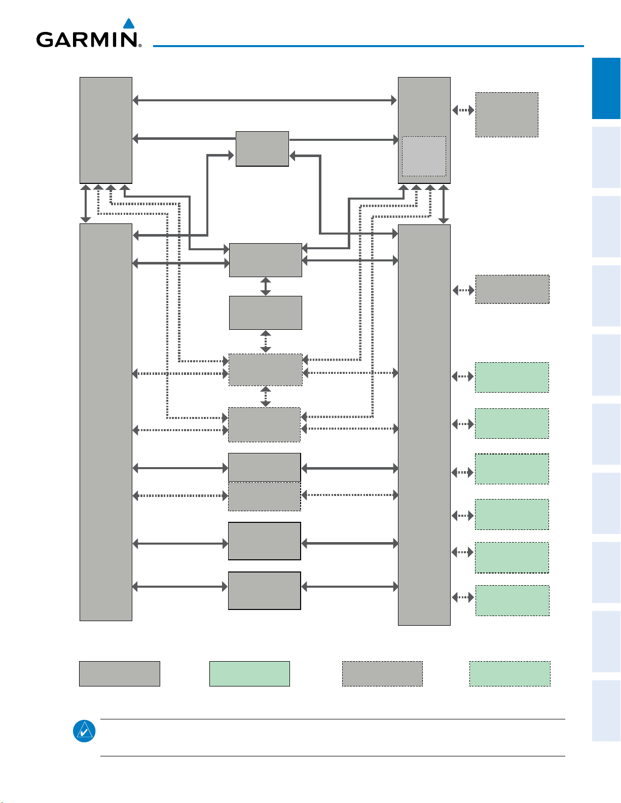
Figure 1-1 shows interactions between the LRUs. Additional/optional equipment are also shown in Figure
1-1. The system is capable of interfacing with the following optional equipment:
•
GDL 69A / GDL 69A SXM
•
GTS 800
•
L3 Stormscope Lightning Strike and Thunderstorm
Traffic Advisory System
Detection
Data Link Receiver
• KN 63 DME
• KR 87 ADF Receiver
• KTA 870 Traffic Avoidance System
• CO Guardian Carbon Monoxide Detection
APPENDICESINDEX
2
Garmin G1000 NXi Pilot’s Guide for Cessna Nav III
190-02177-00 Rev. A
SYSTEM OVERVIEW
Non-Garmin Equipment
Optional
Garmin Equipment
Optional
Non-Garmin Equipment
Garmin Equipment
GTX 345R
Or
#1
GDU 1050
(PFD)
GDL 69A/ GDL
69A SXM (XM
Weather/
Audio Datalink)
GMA 1347
(Audio
Panel)
#1 GIA 63W
(Integrated
Avionics
Unit)
VHF COM
GPS/SBAS
VOR/LOC
G/S
Flight
Director
AFCS Mode
Logic
Servo Logic
#2 GIA 63W
(Integrated
Avionics
Unit)
VHF COM
GPS/SBAS
VOR/LOC
G/S
Flight
Director
AFCS Mode
Logic
Servo Logic
#2
GDU 1054
(MFD)
GEA 71
(Engine &
Airframe I/F)
GTX 335R/33
(Transponder)
GSA 81 (3)
(Servos)
#2 GMU 44
(Magnetometer)
#2 GSU 75
(ADAHRS)
#1 GRS 77/79
(AHRS)
#2 GDC 74A / 72
(Air Data
Computer)
KTA 870
(Traffic
Avoidance)
GTS 800
(TAS)
CO Guardian
(Carbon Monoxide
Detection)
L-3
Stormscope
KN-63
(DME)
KR-87
(ADF Reciever)
ELT
(Emergency Locator
Transmitter)
FS 510
(SD Card
Bluetooth Link)
OVERVIEW
SYSTEM
INSTRUMENTS
FLIGHT
NOTE:
Figure 1-1 System (LRU Configuration)
For information on non-Garmin equipment, consult the applicable optional interface user’s guide.
This document assumes that the reader is already familiar with the operation of this additional equipment.
EIS
AUDIO PANEL
& CNS
MANAGEMENT
FLIGHT
AVOIDANCE
HAZARD
AFCS
ADDITIONAL
FEATURES
APPENDICES INDEX
190-02177-00 Rev. A
Garmin G1000 NXi Pilot’s Guide for Cessna Nav III
3
SYSTEM OVERVIEW
1.2 SYSTEM CONTROLS
SYSTEM
OVERVIEW
FLIGHT
INSTRUMENTS
EIS
& CNS
AUDIO PANEL
FLIGHT
MANAGEMENT
MFD are discussed within the following pages of this section.
NOTE:
The Audio Panel (GMA 1347) is described in the CNS & Audio Panel section.
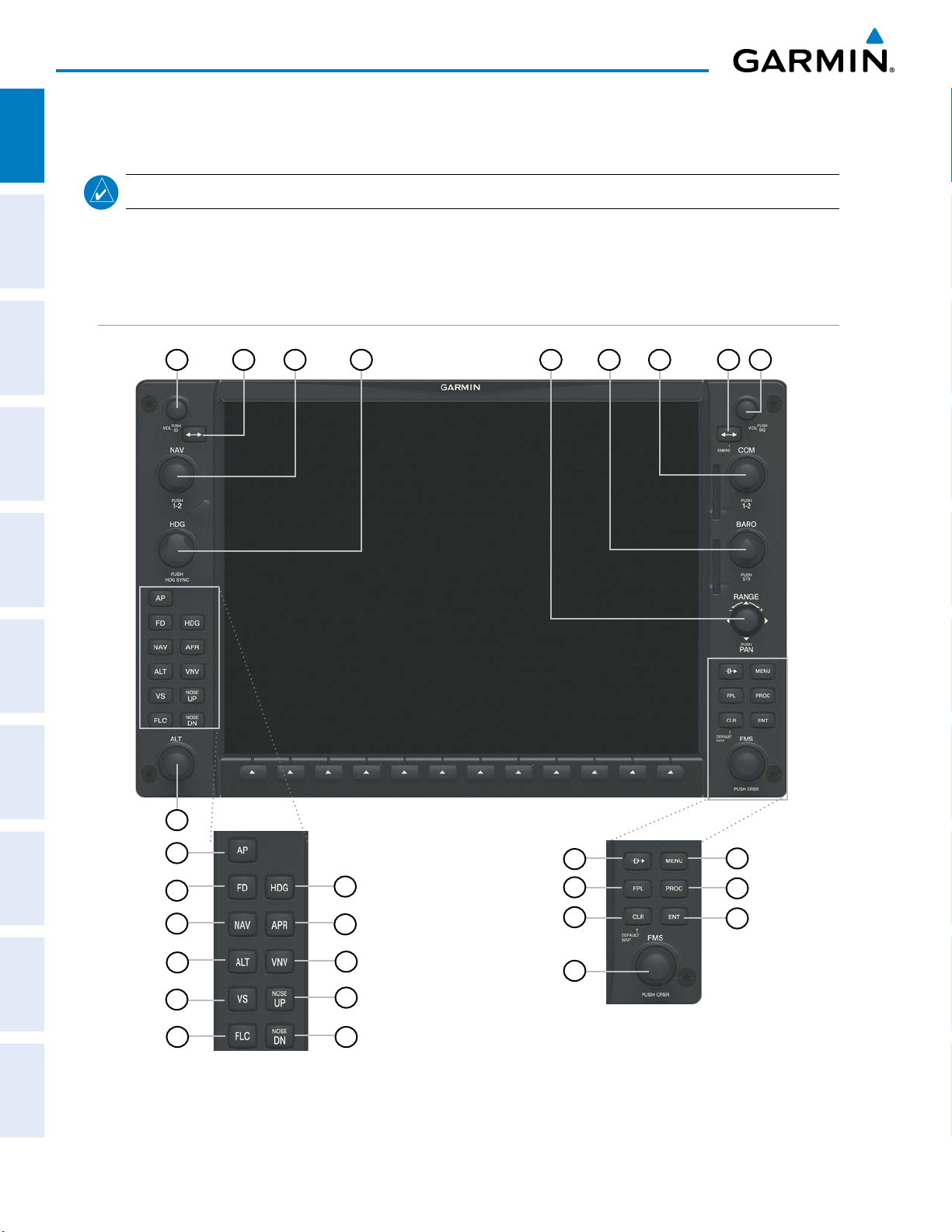
The system controls are located on the PFD and MFD bezels and audio panel. The controls for the PFD and
PFD/MFD CONTROLS
1
2
3
4
5
6
7
9
8
HAZARD
AVOIDANCE
AFCS
FEATURES
ADDITIONAL
APPENDICESINDEX
17
18
19
20
21
22
23
Only with Garmin AFCS
24
25
26
27
28
Figure 1-2 PFD/MFD Controls
10
11
12
16
13
14
15
4
Garmin G1000 NXi Pilot’s Guide for Cessna Nav III
190-02177-00 Rev. A

1
NAV VOL/ID Knob
2
NAV Frequency Transfer Key
3
NAV Knob
4
*Heading Knob
5
Joystick
6
CRS/BARO Knob
7
COM Knob
8
COM Frequency
Transfer Key (EMERG)
9
COM VOL/SQ Knob
SYSTEM OVERVIEW
OVERVIEW
SYSTEM
Turn to control NAV audio volume (shown in the NAV Frequency Box as a percentage)
Press to toggle Morse code identifier audio ON/OFF
Transfers the standby and active NAV frequencies
INSTRUMENTS
Turn to tune NAV receiver standby frequencies (large knob for MHz; small for kHz)
Press to toggle cyan tuning box between NAV1 and NAV2
Turn to manually select a heading. When operating in Heading Select mode, this knob provides the heading reference to the flight director.
Press to display a digital heading momentarily to the left of the HSI and synchronize the Selected Heading to the current heading
Turn to change map range
Press to activate Map Pointer for map panning
Turn large knob for altimeter barometric pressure setting
Turn the small knob to set the pilot-selected course on the HSI when the VOR1, VOR2, or
OBS/SUSP mode is selected. Pressing this knob centers the CDI on the currently selected
VOR. The pilot-selected course provides course reference to the pilot-side flight director
when operating in Navigation and Approach modes.
Press to re-center the CDI and return course pointer directly TO bearing of active waypoint/
station
Turn to tune COM transceiver standby frequencies (large knob for MHz; small for kHz)
Press to toggle cyan tuning box between COM1 and COM2
The selected COM (green) is controlled with the COM MIC Key (Audio Panel).
Transfers the standby and active COM frequencies
Press and hold two seconds to tune the emergency frequency (121.5 MHz) automatically into
the active frequency field
Turn to control COM audio volume level (shown as a percentage in the COM Frequency Box)
Press to turn the COM automatic squelch ON/OFF
FLIGHT
EIS
AUDIO PANEL
& CNS
MANAGEMENT
FLIGHT
AVOIDANCE
HAZARD
AFCS
10
Direct-to Key ( )
11
FPL Key
12
CLR Key
(DFLT MAP)
13
MENU Key
14
PROC Key
15
ENT Key
190-02177-00 Rev. A
Activates the direct-to function and allows the user to enter a destination waypoint and establish a direct course to the selected destination (specified by identifier, chosen from the
active route)
Displays flight plan information
Erases information, cancels entries, or removes menus
Press and hold to display the MFD Navigation Map Page (MFD only).
Displays a context-sensitive list of options for accessing additional features or making setting
changes
Gives access to IFR departure procedures (DPs), arrival procedures (STARs), and approach
procedures (IAPs) for a flight plan or selected airport
Validates/confirms menu selection or data entry
Garmin G1000 NXi Pilot’s Guide for Cessna Nav III
5
ADDITIONAL
FEATURES
APPENDICES INDEX

SYSTEM OVERVIEW
SYSTEM
OVERVIEW
FLIGHT
INSTRUMENTS
EIS
& CNS
AUDIO PANEL
FLIGHT
MANAGEMENT
16
FMS Knob
(Flight Management
System Knob)
Press to turn the selection cursor ON/OFF.
Data Entry: With cursor ON, turn to enter data in the highlighted field (large knob moves
cursor location; small knob selects character for highlighted cursor location)
Scrolling: When a list of information is too long for the window/box, a scroll bar appears,
indicating more items to view. With cursor ON, turn large knob to scroll through the list.
Page Selection: Turn knob on MFD to select the page to view (large knob selects a page
group; small knob selects a specific page from the group)
17
*ALT Knob
Sets the selected altitude in the Selected Altitude Box (the large knob selects the thousands,
the small knob selects the hundreds). In addition to providing the standard system altitude
alerter function, selected altitude provides an altitude setting for the Altitude Capture/Hold
mode of the AFCS
18
**AP Key
Engages/disengages the Autopilot and Flight Director in the default vertical and lateral
modes.
19
**FD Key Activates/deactivates the Flight Director only. Pressing the FD key turns on the Flight Direc-
tor in the default vertical and lateral modes. Pressing the FD key again deactivates the Flight
Director and removes the command bars, unless the Autopilot is engaged. If the Autopilot
is engaged, the FD key is disabled.
20
**NAV Key
21
**ALT Key
22
**VS Key
23
**FLC Key
Selects/deselects the Navigation mode.
Selects/deselects the Altitude Hold mode.
Selects/deselects the Vertical Speed mode.
Selects/deselects the Flight Level Change mode.
HAZARD
AVOIDANCE
AFCS
FEATURES
ADDITIONAL
APPENDICESINDEX
24
**HDG Key
25
**APR Key
26
**VNV Key
Selects/deselects the Heading Select mode.
Selects/deselects the Approach mode.
Selects/deselects Vertical Navigation mode
(if equipped)
27
**NOSE UP Key
Controls the active pitch reference for the Pitch Hold, Vertical Speed, and Flight Level
Change modes.
28
**NOSE DN Key
Controls the active pitch reference for the Pitch Hold, Vertical Speed, and Flight Level
Change modes.
*This Key only appears on the MFD.
**This Key only appears on the MFD with Garmin AFCS option.
6
Garmin G1000 NXi Pilot’s Guide for Cessna Nav III
190-02177-00 Rev. A

SECURE DIGITAL CARDS
SYSTEM OVERVIEW
OVERVIEW
SYSTEM
NOTE:
NOTE:
Refer to the Appendices for instructions on updating the aviation databases.
Ensure that the system is powered off before inserting the SD card.
The GDU 1050/1054 data card slots use Secure Digital (SD) cards and are located on the top right portion
of the display bezels. Each display bezel is equipped with two SD card slots. SD cards are used for aviation
database and system software updates as well as terrain database storage. Also, flight plans may be imported or
exported from an SD card in the MFD.
Installing and removing an SD card
Insert the SD card in the SD card slot, pushing the card in until the spring latch engages. The front of the card
should remain flush with the face of the display bezel. To remove, gently press on the SD card to release the
spring latch and eject the card.
INSTRUMENTS
FLIGHT
EIS
AUDIO PANEL
& CNS
MANAGEMENT
FLIGHT
AVOIDANCE
HAZARD
SD Card Slots
Figure 1-3 PFD/MFD Display Bezel SD Card Slots
AFCS
ADDITIONAL
FEATURES
APPENDICES INDEX
190-02177-00 Rev. A
Garmin G1000 NXi Pilot’s Guide for Cessna Nav III
7

SYSTEM OVERVIEW
1.3 SYSTEM OPERATION
SYSTEM
OVERVIEW
FLIGHT
INSTRUMENTS
This section discusses powering up the system, normal and reversionary display operation, system status,
ADAHRS/AHRS modes of operation, and GPS receiver operation.
SYSTEM POWER-UP
NOTE:
Refer to the Appendices for ADAHRS/AHRS initialization bank angle limitations.
EIS
& CNS
AUDIO PANEL
FLIGHT
MANAGEMENT
HAZARD
AVOIDANCE
AFCS
NOTE:
NOTE:
See the Appendices for additional information regarding system-specific annunciations and alerts.
See the Pilot’s Operating Handbook (POH) for specific procedures concerning avionics power
application and emergency power supply operation.
The system is integrated with the aircraft electrical system and receives power directly from electrical busses.
The PFD, MFD, and supporting sub-systems include both power-on and continuous built-in test features that
exercise the processor, RAM, ROM, external inputs and outputs to provide safe operation.
When powering up the system, test annunciations are displayed and key annunciator lights also become
momentarily illuminated on the audio panel and the display bezels. On the PFD, the ADAHRS/AHRS begins
to initialize and displays ‘ADAHRS/DG ALIGN: Remain Stationary’. All system annunciations should disappear
typically within one minute of power-up.
When the MFD powers up, the MFD Power-up Page displays the following information:
• System version • Navigation database name and effective dates
• Land database name and version • Airport Directory name and effective dates
• Safe Taxi database name and effective dates • FliteCharts/ChartView database information
• Terrain database name and version • Copyright
• Obstacle database name and effective dates
Current database information includes the valid operating dates, cycle number and database type. When this
information has been reviewed for currency (to ensure that no databases have expired), the pilot is prompted to
continue. Pressing the
ENT
Key acknowledges this information and displays the Navigation Map Page on the
MFD.
FEATURES
ADDITIONAL
APPENDICESINDEX
8
Garmin G1000 NXi Pilot’s Guide for Cessna Nav III
190-02177-00 Rev. A
SYSTEM OVERVIEW
OVERVIEW
SYSTEM
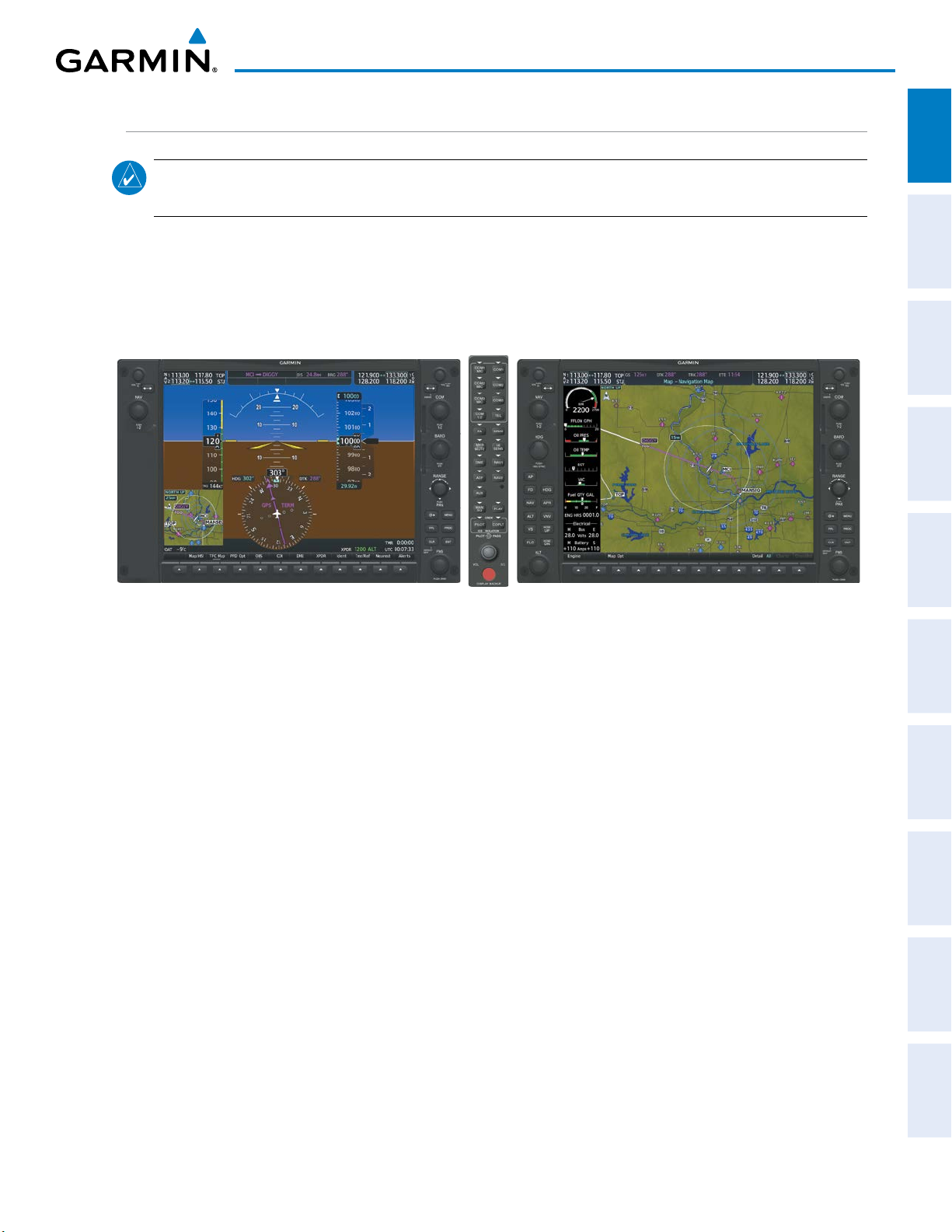
NORMAL OPERATION
NOTE:
In normal operating mode, backlighting can only be adjusted from the PFD (see Section 1.5). In
reversionary mode, it can be adjusted from the remaining display.
In normal operating mode, the PFD presents graphical flight instrumentation (attitude, heading, airspeed,
altitude, vertical speed), replacing the traditional flight instrument cluster (see the Flight Instruments Section
for more information). The MFD normally displays a full-color moving map with navigation information (see
the Flight Management Section), while the left portion of the MFD is dedicated to the Engine Indication System
(see the EIS Section). Both displays offer control for COM and NAV frequency selection.
INSTRUMENTS
FLIGHT
EIS
AUDIO PANEL
& CNS
Figure 1-4 System Normal Operation
MANAGEMENT
FLIGHT
AVOIDANCE
HAZARD
AFCS
ADDITIONAL
FEATURES
APPENDICES INDEX
190-02177-00 Rev. A
Garmin G1000 NXi Pilot’s Guide for Cessna Nav III
9
SYSTEM OVERVIEW
REVERSIONARY MODE
SYSTEM
OVERVIEW
NOTE:
further information regarding system-specific alerts.
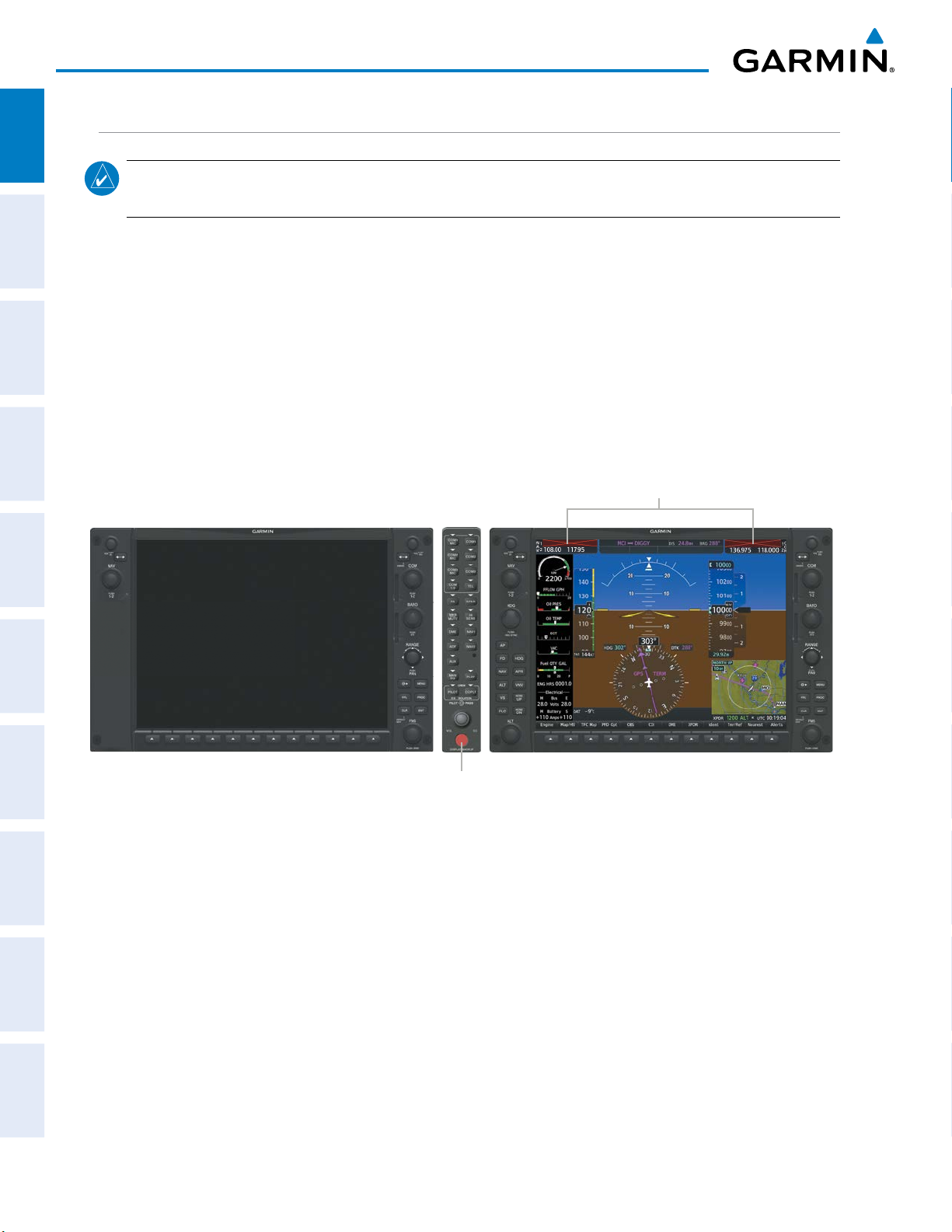
In the event of a display failure, the system can be manually switched to reversionary (backup) mode (all
FLIGHT
INSTRUMENTS
EIS
remaining displays enter reversionary mode). In reversionary mode, all important flight information is presented
on the remaining display(s) in the same format as in normal operating mode.
If a display fails, the appropriate IAU-display Ethernet interface is cut off. Thus, the IAU can no longer
communicate with the remaining display (refer to Figure 1-5), and the NAV and COM functions provided to the
failed display by the IAU are flagged as invalid on the remaining display. The system reverts to backup paths for
the ADAHRS/AHRS, ADC, Engine/Airframe Unit, and Transponder, as required. The change to backup paths
is completely automated for all LRUs and no pilot action is required.
The system alerts the pilot when backup paths are utilized by the LRUs. Refer to the Appendices for
& CNS
AUDIO PANEL
FLIGHT
MANAGEMENT
HAZARD
AVOIDANCE
AFCS
Reversionary mode may be manually activated by pressing the Audio Panel’s red
Pressing this button again deactivates reversionary mode.
NAV1 and COM1 Flagged Invalid (provided by the failed PFD)
Manually Activates/Deactivates Reversionary Mode on All Displays
DISPLAY BACKUP
Figure 1-5 Reversionary Mode (Failed PFD)
Button
DISPLAY BACKUP
Button.
FEATURES
ADDITIONAL
APPENDICESINDEX
10
Garmin G1000 NXi Pilot’s Guide for Cessna Nav III
190-02177-00 Rev. A

SYSTEM ANNUNCIATIONS
SYSTEM OVERVIEW
OVERVIEW
SYSTEM
NOTE:
Upon power-up, certain windows remain invalid as system equipment begins to initialize. All windows
should be operational within one minute of power-up. If any window continues to remain flagged, the
system should be serviced by a Garmin-authorized repair facility.
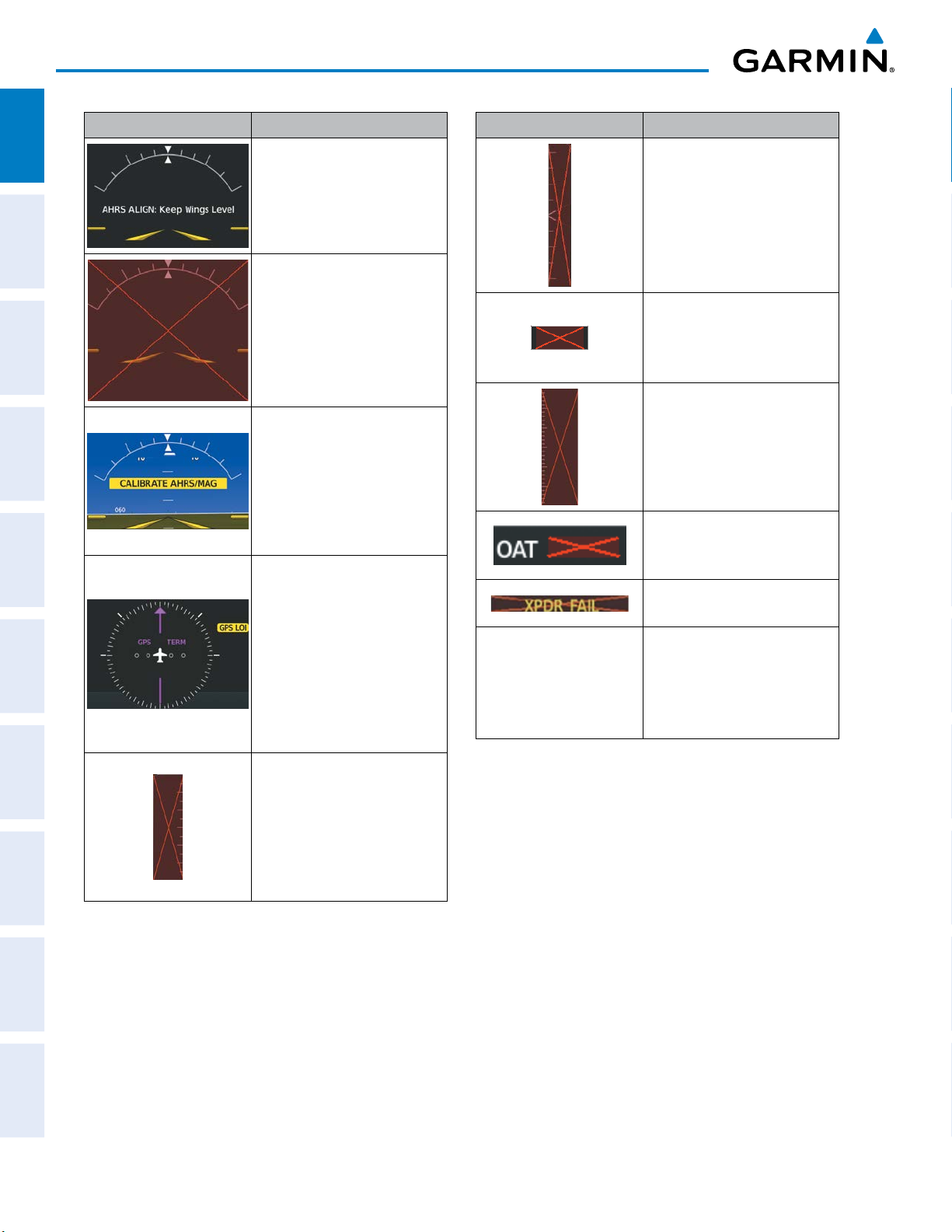
When an LRU or an LRU function fails, a large red ‘X’ is typically displayed on windows associated with the
failed data (refer to Table 1-1 for all possible flags and the responsible LRUs). Refer to the Pilot’s Operating
Handbook (POH) for additional information regarding pilot responses to these annunciations.
The status of detected LRUs can be checked on the Aux - System Status Page. Active LRUs are indicated by
green check marks; failed by red or amber ‘X’s. Failed LRUs should be noted and a service center or Garminauthorized dealer informed.
Viewing LRU information:
1) Use the FMS Knob to select the Aux - System Status Page.
2) To place the cursor in the ‘LRU Info’ Box,
Press the LRU Softkey.
Or:
a) Press the MENU Key.
b) With ‘Select LRU Window’ highlighted, press the ENT Key.
3) Use the FMS Knob to scroll through the box to view LRU status information.
INSTRUMENTS
FLIGHT
EIS
AUDIO PANEL
& CNS
MANAGEMENT
FLIGHT
AVOIDANCE
HAZARD
NOTE:
Refer to the POH for additional information regarding pilot responses to these annunciations.
AFCS
ADDITIONAL
FEATURES
APPENDICES INDEX
190-02177-00 Rev. A
Garmin G1000 NXi Pilot’s Guide for Cessna Nav III
11
SYSTEM OVERVIEW
SYSTEM
OVERVIEW
FLIGHT
INSTRUMENTS
EIS
& CNS
AUDIO PANEL
FLIGHT
MANAGEMENT
HAZARD
AVOIDANCE
System Annunciation Comment
Air Data, Attitude and Heading
Reference System is aligning.
Display system is not receiving
attitude information from the
ADAHRS/AHRS.
Air Data, Attitude, and Heading
calibration incomplete or
configuration module failure.
GPS information is either
not present or is invalid
for navigation use. Note
that ADAHRS/AHRS utilizes
GPS inputs during normal
operation. ADAHRS/AHRS
operation may be degraded
if GPS signals are not present
(see POH).
System Annunciation Comment
Display system is not receiving
vertical speed input from the
air data computer.
Display system is not
receiving valid heading input
from the ADAHRS/AHRS or
magnetometer.
Display system is not receiving
altitude input from the air data
computer.
Display system is not receiving
valid OAT information from the
air data computer.
Display system is not receiving
valid transponder information.
A red ‘X’ through any other
Other Various Red X
Indications
display field (such as engine
instrumentation fields)
indicates that the field is not
receiving valid data.
AFCS
FEATURES
ADDITIONAL
APPENDICESINDEX
12
Display system is not receiving
airspeed input from the air
data computer.
Table 1-1 System Annunciations
Garmin G1000 NXi Pilot’s Guide for Cessna Nav III
190-02177-00 Rev. A
SYSTEM OVERVIEW
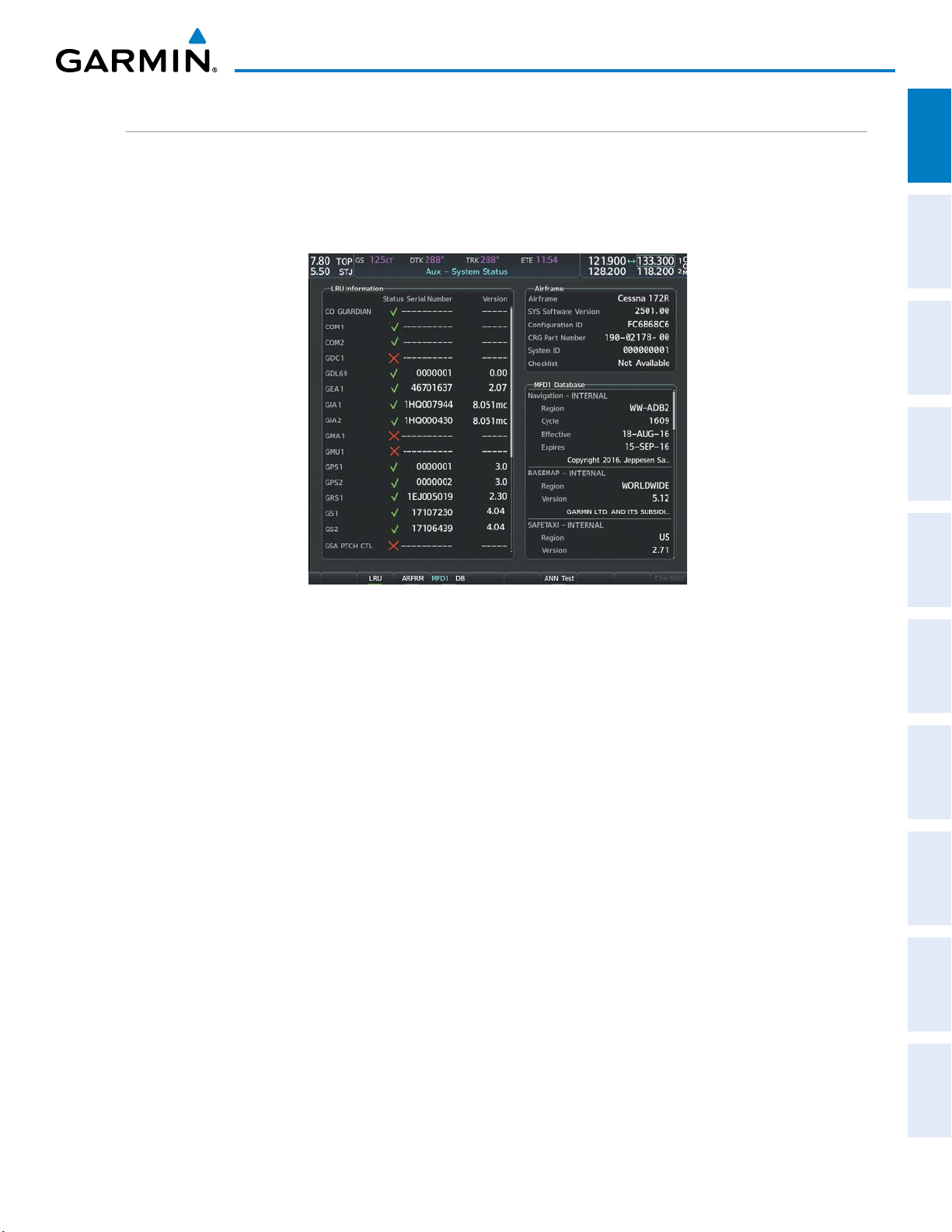
SYSTEM STATUS
The System Status Page displays the status and software version numbers for all detected system LRUs.
Pertinent information on all system databases is also displayed. Active LRUs are indicated by green check marks
and failed LRUs are indicated by red “X”s. Failed LRUs should be noted and a service center or Garmin dealer
informed.
OVERVIEW
SYSTEM
INSTRUMENTS
FLIGHT
EIS
AUDIO PANEL
& CNS
Figure 1-6 Example System Status Page
The LRU and ARFRM Softkeys on the System Status Page select the applicable list (LRU Information or
Airframe window) through which the FMS Knob can be used to scroll information within the selected window.
Pressing the MFD1 DB Softkey (label annunciator turns green indicting the softkey is selected) places the
cursor in the database window. Use the FMS Knob to scroll through database information for the MFD.
Pressing the softkey again will change the softkey label to PFD1 DB. PFD 1 database information is now
displayed in the database window. Pressing the softkey a third time will change the softkey label back to MFD1
DB. MFD database information is displayed again in the database window.
The ANN Test Softkey, when selected, causes an annunciation test tone to be played.
MANAGEMENT
FLIGHT
AVOIDANCE
HAZARD
AFCS
ADDITIONAL
FEATURES
APPENDICES INDEX
190-02177-00 Rev. A
Garmin G1000 NXi Pilot’s Guide for Cessna Nav III
13
SYSTEM OVERVIEW
ADAHRS OPERATION
SYSTEM
OVERVIEW
FLIGHT
INSTRUMENTS
EIS
& CNS
AUDIO PANEL
FLIGHT
MANAGEMENT
In addition to using internal sensors, the GSU 75 ADAHRS uses GPS information, magnetic field data and
air data to assist in attitude/heading calculations. In normal mode, the ADAHRS relies upon GPS and magnetic
field measurements. If either of these external measurements is unavailable or invalid, the ADAHRS uses air
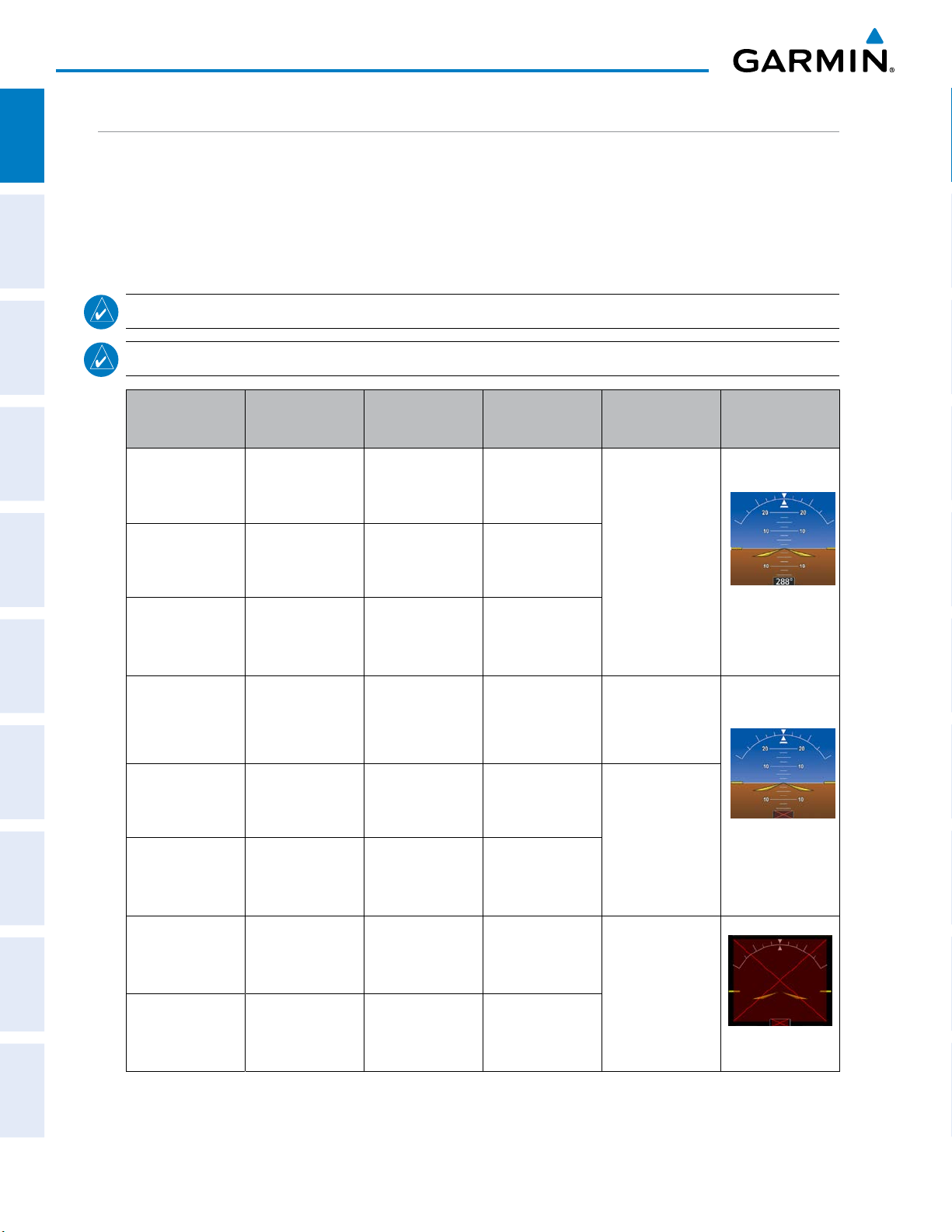
data information for attitude determination. Eight ADAHRS modes of operation are available (see Table 1-1)
and depend upon the combination of available sensor inputs. Loss of air data, GPS, or magnetometer sensor
inputs is communicated to the pilot by system messages.
NOTE:
NOTE:
Refer to the Appendices for specific AHRS and ADC system message information.
Aggressive maneuvering while the ADAHRS is not operating normally can degrade ADAHRS accuracy.
ADAHRS Mode GPS Data
Available
Magnetometer
Data Available
Air Data
Available
Condition Attitude
Indicator
ADAHRS Normal Yes Yes Yes
ADAHRS no-Air
Data
Yes Yes No
Valid Pitch/Roll/
Heading.
HAZARD
AVOIDANCE
AFCS
FEATURES
ADDITIONAL
APPENDICESINDEX
ADAHRS no-GPS No Ye s Ye s
ADAHRS no-GPS/
no-Mag
ADAHRS no-Mag
Data
ADAHRS no-Mag/
no-Air Data
No No Yes
Yes No Yes
Yes No No
ADAHRS coast-
on-gyros until
No Yes No
invalid
ADAHRS no-Mag/
coast-on-gyros
No No No
until invalid
Valid Pitch/Roll.
Heading will coast-
on-gyros until it
becomes invalid.
Valid Pitch/Roll.
Invalid Heading.
Invalid Pitch/Roll/
Heading.
14
Table 1-2 ADAHRS Operation
Garmin G1000 NXi Pilot’s Guide for Cessna Nav III
190-02177-00 Rev. A
AHRS OPERATION
SYSTEM OVERVIEW
OVERVIEW
SYSTEM
NOTE:
NOTE:
Refer to the Appendices for specific AHRS alert information.
INSTRUMENTS
FLIGHT
Aggressive maneuvering while AHRS is not operating normally may degrade AHRS accuracy.
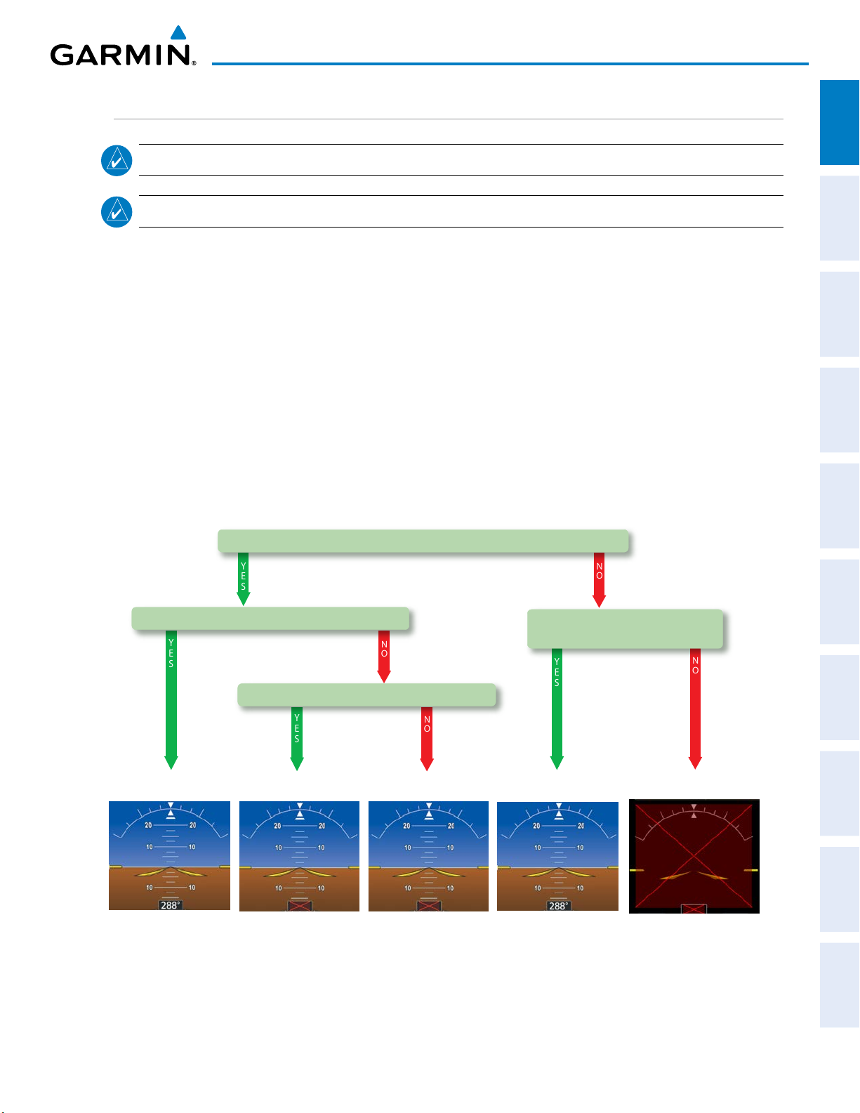
In addition to using internal sensors, the AHRS uses GPS information, magnetic field data and air data
to assist in attitude/heading calculations. In normal mode, the AHRS relies upon GPS and magnetic field
measurements. If either of these external measurements is unavailable or invalid, the AHRS uses air data
information for attitude determination. Four AHRS modes of operation are available and depend upon the
EIS
combination of available sensor inputs. Loss of air data, GPS, or magnetometer sensor inputs is communicated
to the pilot by message advisory alerts.
The AHRS corrects for shifts and variations in the Earth’s magnetic field by applying the Magnetic Field
Variation Database. The Magnetic Field Variation Database is derived from the International Geomagnetic
AUDIO PANEL
& CNS
Reference Field (IGRF). The IGRF is a mathematical model that describes the Earth’s main magnetic field and its
annual rate of change. The database is updated approximately every 5 years. See the Appendices for information
on updating the Magnetic Field Variation Database. The system will prompt you on startup when an update is
available. Failure to update this database could lead to erroneous heading information being displayed to the
MANAGEMENT
FLIGHT
pilot.
YES
GPS Data Available and Reliable?
NO
AVOIDANCE
HAZARD
Mag Data Available and Reliable?
YES
Air Data Available and Reliable?
YES
AHRS Normal
Mode
AHRS no-Mag
Mode
Heading Invalid Heading Invalid Attitude/Heading Invalid
NO
NO
AHRS no-Mag/
no-Air Mode
Figure 1-7 AHRS Operation
Mag Data AND Air Data
Available and Reliable?
YES
AHRS no-GPS
Mode
AHRS coast-on-gyros
NO
until invalid
AFCS
ADDITIONAL
FEATURES
APPENDICES INDEX
190-02177-00 Rev. A
Garmin G1000 NXi Pilot’s Guide for Cessna Nav III
15

SYSTEM OVERVIEW
GPS INPUT FAILURE
SYSTEM
OVERVIEW
NOTE:
true air speed values greater than approximately 200 knots, is not guaranteed. Under these rare conditions,
it is possible for in-flight ADAHRS/AHRS initialization to take an indefinite amount of time which would
result in an extended period of time where valid ADAHRS/AHRS outputs are unavailable.
FLIGHT
INSTRUMENTS
The system provides two sources of GPS information. If a single GPS receiver fails, or if the information
provided from one of the GPS receivers is unreliable, the ADAHRS/AHRS seamlessly transitions to using
the other GPS receiver. An alert message informs the pilot of the use of the backup GPS path. If both GPS
EIS
inputs fail, the ADAHRS/AHRS continues to operate in reversionary No-GPS mode so long as the air data and
magnetometer inputs are available and valid.
AIR DATA INPUT FAILURE
In-flight initialization of ADAHRS/AHRS, when operating without any valid source of GPS data and at
& CNS
AUDIO PANEL
FLIGHT
MANAGEMENT
HAZARD
AVOIDANCE
AFCS
FEATURES
ADDITIONAL
A failure of the air data input has no effect on ADAHRS/AHRS output while ADAHRS/AHRS is operating in
normal mode. A failure of the air data input while the ADAHRS/AHRS is operating in reversionary No-GPS
mode results in invalid attitude and heading information on the PFD (as indicated by red “X” flags).
MAGNETOMETER FAILURE
If the magnetometer input fails, the ADAHRS/AHRS transitions to one of the reversionary No-Magnetometer
modes and continues to output valid attitude information. However, if the aircraft is airborne, the heading
output on the PFD does become invalid (as indicated by a red “X”).
GPS RECEIVER OPERATION
Each GIA 63W Integrated Avionics Unit (IAU) contains a GPS receiver. Information collected by the specified
receiver (GPS1 for the #1 IAU or GPS2 for the #2 IAU) may be viewed on the Aux - GPS Status Page.
These GPS sensor annunciations are most often seen after system power-up when one GPS receiver has
acquired satellites before the other, or one of the GPS receivers has not yet acquired a SBAS signal. While
the aircraft is on the ground, the SBAS signal may be blocked by obstructions causing one GPS receiver to
have difficulty acquiring a good signal. Also, while airborne, turning the aircraft may result in one of the GPS
receivers temporarily losing the SBAS signal.
If the sensor annunciation persists, check for a system failure message in the Messages Window on the PFD.
If no failure message exists, check the GPS Status Page and compare the information for GPS1 and GPS2.
Discrepancies may indicate a problem.
APPENDICESINDEX
16
Garmin G1000 NXi Pilot’s Guide for Cessna Nav III
190-02177-00 Rev. A
 Loading...