

Garmin G1000 NAV III Line Maintenance Manual
G1000 NAV III
LINE MAINTENANCE MANUAL
190-00352-00 March 2008 Rev. L
© Copyright 2004-2008
Garmin Ltd. or its subsidiaries
All Rights Reserved
Except as expressly provided herein, no part of this manual may be reprod uced, copied, transmitted, disseminated,
downloaded or stored in any storage medium, for any purpose without the express prior written consent of Garmin. Garmin
hereby grants permission to download a single copy of this manual and of any revision to this manual onto a hard drive or
other electronic storage medium to be viewed and to print one copy of this manual or of any revision hereto, provided that
such electronic or printed copy of this manual or revision must contain the complete text of this copyright notice and
provided further that any unauthorized commercial distribution of this manual or any revision hereto is strictly prohibited.
Garmin International, Inc.
1200 E. 151
st
Street
Olathe, KS 66062 USA
Telephone: 913-397-8200
Aviation Panel-Mount Technical Support Line (Toll Free): 1-888-606-5482
www.garmin.com
Garmin (Europe) Ltd.
Liberty House, Bulls Copse Road, Hounsdown Business Park
Southampton, SO40 9RB, U.K.
Telephone: +44 (0) 870 8501241
RECORD OF REVISIONS
Revision Revision
Description
Date
A 6/24/04 Production release, no major changes
B 12/15/04 Made minor changes to software loading procedure (Section 4)
C 2/24/05 Made document Nav III specific and updated for new software
(GDU 4.03)
D 3/11/05 Changed GDU software version to 4.04
E 2/1/06
F 6/16/06
G 12/6/06
H 1/11/07
J 07/09/07
K 07/16/07
L 3/20/08
Updated manual for BP 2006
Expanded troubleshoot section
Updated manual for BP 2007
Expanded GDC testing section
Updated Manual per System Software v563.03
Added Power Interrupt Tests to Section 6
Updated for system software 0563.06
DOCUMENT PAGINATION
Section Pages
Table of Contents i-viii
Section 1 1-1 to 1-18
Section 2 2-1 to 2-92
Section 3 3-1 to 3-6
Section 4 4-1 to 4-48
Section 5 5-1 to 5-4
Section 6 6-1 to 6-6
Appendix A A-1 to A-30
Appendix B B-1 to B-34
Page A G1000 Nav III Line Maintenance Manual
Rev. L 190-00352-00

This manual was written for Cessna Nav III G1000 System Software version 0563.06 or later approved
software. Some differences in operation may be observed when comparing the information in this manual
to earlier or later software versions.
This manual is written for the following NAV III aircraft models:
• Cessna Skyhawk 172R and 172S
• Cessna Skylane 182T
• Cessna Turbo Skylane T182T
• Cessna Stationair 206H
• Cessna Turbo Stationair T206H
The following are General Safety Precautions that are not related to any specific procedure and therefore
do not appear elsewhere in this maintenance manual. These are recommended precautions that personnel
should understand and apply during the many phases of maintenance and repair.
KEEP AWAY FROM LIVE CIRCUITS. Maintenance personnel shall observe all safety regulations
at all times. Turn off system power before making or breaking electrical connections. Regard any exposed
connector, terminal board, or circuit board as a possible shock hazard. Components which retain a charge
shall be discharged only when such grounding does not result in equipment damage. If a test connection
to energized equipment is required, make the test equipment ground connection before probing the
voltage or signal to be tested.
DO NOT SERVICE ALONE. Personnel shall not under any circumstances reach into or enter any
enclosure for the purpose of servicing or adjusting the equipment without immediate presence or
assistance of another person capable of rendering aid.
INFORMATION SUBJECT TO EXPORT CONTROL LAWS
This document may contain information which is subject to the Export Administration Regulations
("EAR") issued by the United States Department of Commerce (15 CFR, Chapter VII, Subchapter C) and
which may not be exported, released, or disclosed to foreign nationals inside or outside of the United
States without first obtaining an export license. A violation of the EAR may be subject to a penalty of up
to 10 years imprisonment and a fine of up to $1,000,000 under Section 2410 of the Export Administration
Act of 1979. Include this notice with any reproduced portion of this document.
WARNING
This product, its packaging, and its components contain chemicals known to the State of
California to cause cancer, birth defects, or reproductive harm. This Notice is being
provided in accordance with California's Proposition 65. If you have any questions or
would like additional information, please refer to our web site at
www.garmin.com/prop65
.
G1000 Nav III Line Maintenance Manual Page i
190-00352-00 Rev. L

WARNING
The GDU 104X lamps contain mercury and must be recycled or disposed of according to
local, state, or federal laws. If you have any questions or would like additional
information, please refer to our web site at
www.garmin.com/aboutGarmin/environment/disposal.jsp
.
CAUTION
The GDU 104X lens is coated with a special anti-reflective coating which is very
sensitive to skin oils, waxes and abrasive cleaners. CLEANERS CONTAINING
AMMONIA WILL HARM THE ANTI-REFLECTIVE COATING. It is very important
to clean the lens using a clean, lint-free cloth and an eyeglass lens cleaner that is specified
as safe for anti-reflective coatings.
CAUTION
All G1000 screen shots used in this document are only intended to serve as a visual
reference. All information depicted in screen shots, including software version and part
numbers, is subject to change and may not be up to date.
Page ii G1000 Nav III Line Maintenance Manual
Rev. L 190-00352-00

TABLE OF CONTENTS
PARAGRAPH PAGE
1 GENERAL DESCRIPTION..............................................................................................................1-1
1.1 Introduction........................................................................................................................................1-1
1.2 LRU Description................................................................................................................................1-2
1.3 G1000 Block Diagrams .....................................................................................................................1-6
1.4 User Interface.....................................................................................................................................1-9
1.5 Recommended Tools .......................................................................................................................1-17
2 TROUBLESHOOTING.....................................................................................................................2-1
2.1 G1000 Alerting System .....................................................................................................................2-1
2.2 GDU 104X.......................................................................................................................................2-19
2.3 GMA 1347.......................................................................................................................................2-38
2.4 GIA 63/GIA 63W ............................................................................................................................2-43
2.5 GRS 77/GMU 44.............................................................................................................................2-55
2.6 GDC 74A.........................................................................................................................................2-59
2.7 GEA 71............................................................................................................................................2-61
2.8 GTX 33............................................................................................................................................2-74
2.9 GDL 69/69A....................................................................................................................................2-75
2.10 GDL 90 ............................................................................................................................................2-78
2.11 GFC 700 (BP 2007 and later only) ..................................................................................................2-79
2.12 Backshell Connectors ......................................................................................................................2-88
3 EQUIPMENT REMOVAL & INSTALLATION ............................................................................3-1
3.1 GDU 104X.........................................................................................................................................3-1
3.2 GMA 1347.........................................................................................................................................3-1
3.3 GIA 63/GIA 63W ..............................................................................................................................3-1
3.4 GRS 77/GMU 44 ..............................................................................................................................3-2
3.5 GDC 74A...........................................................................................................................................3-2
3.6 GEA 71..............................................................................................................................................3-2
3.7 GTX 33..............................................................................................................................................3-3
3.8 GDL 69/69A......................................................................................................................................3-3
3.9 GDL 90..............................................................................................................................................3-3
3.10 GSA 81..............................................................................................................................................3-3
3.11 GSM 85..............................................................................................................................................3-4
3.12 Configuration Module........................................................................................................................3-5
3.13 GEA 71 Backshell Thermocouple .....................................................................................................3-6
G1000 Nav III Line Maintenance Manual Page iii
190-00352-00 Rev. L

4 UPLOADING SOFTWARE, CONFIGURING, & TESTING .........................................................4-1
4.1 GDU 104X.........................................................................................................................................4-1
4.2 GMA 1347.........................................................................................................................................4-5
4.3 GIA 63/GIA 63W ..............................................................................................................................4-8
4.4 GRS 77/GMU 44.............................................................................................................................4-17
4.5 GDC 74A.........................................................................................................................................4-30
4.6 GEA 71............................................................................................................................................4-34
4.7 GTX 33............................................................................................................................................4-38
4.8 GDL 69A.........................................................................................................................................4-41
4.9 GDL 90............................................................................................................................................4-44
4.10 GSA 81............................................................................................................................................4-44
5 FINAL SYSTEM CHECKOUT........................................................................................................5-1
5.1 GPS Failure Test................................................................................................................................5-1
5.2 GIA Failure Test................................................................................................................................5-2
5.3 Display Failure Test...........................................................................................................................5-2
5.4 AHRS/Air Data Backup Path Test.....................................................................................................5-3
5.5 Flight Test..........................................................................................................................................5-3
6 PERIODIC MAINTENANCE ..........................................................................................................6-1
6.1 Introduction........................................................................................................................................6-1
6.2 GFC 700 Visual Inspection Procedure ..............................................................................................6-3
6.3 GSA 81 Greasing Procedure ..............................................................................................................6-3
6.4 GSM Slip Clutch Checking and Adjustment Procedure....................................................................6-3
6.5 Category A Long Term Power Interrupt Annual Inspection Procedure............................................6-4
APPENDIX A G1000 PINOUT LIST.....................................................................................................A-1
A.1 GIA 63/GIA 63W .............................................................................................................................A-1
A.2 GDU 104X......................................................................................................................................A-12
A.3 GRS 77............................................................................................................................................A-14
A.4 GMU 44..........................................................................................................................................A-15
A.5 GDC 74A........................................................................................................................................A-16
A.6 GEA 71...........................................................................................................................................A-18
A.7 GMA 1347......................................................................................................................................A-22
A.8 GTX 33...........................................................................................................................................A-26
A.9 GDL 69/69A...................................................................................................................................A-28
A.10 GSA 81 ...........................................................................................................................................A-30
Page iv G1000 Nav III Line Maintenance Manual
Rev. L 190-00352-00

APPENDIX B G1000 SYSTEM SOFTWARE & CONFIGURATION................................................. B-1
B.1 Initial Software & Configuration Overview..................................................................................... B-2
B.2 Final Configuration Items...............................................................................................................B-24
B.3 Software/Configuration Troubleshooting....................................................................................... B-26
B.4 System Communication Hierarchy................................................................................................. B-27
B.5 Aviation Database...........................................................................................................................B-28
B.6 TAWS Configuration......................................................................................................................B-29
B.7 SD Card Use ................................................................................................................................... B-31
G1000 Nav III Line Maintenance Manual Page v
190-00352-00 Rev. L

LIST OF FIGURES
FIGURE PAGE
1-1 Typical Cessna Nav III G1000 System Interconnect.........................................................................1-6
1-2 G1000 Flight Instrumentation Data Paths..........................................................................................1-7
1-3 G1000 Navigation/Communication Data Paths.................................................................................1-8
1-4 GDU 104X Control Interface ............................................................................................................1-9
1-5 GMA 1347 Control Interface.............................................................................................................1-9
1-6 FMS Control Knob..........................................................................................................................1-10
1-7 G1000 Softkeys ...............................................................................................................................1-11
1-8 Configuration Mode Navigation......................................................................................................1-11
1-9 G1000 Configuration Storage..........................................................................................................1-14
1-10 GRS/GDC Configuration Storage ...................................................................................................1-15
1-11 SET/ACTV Feature .........................................................................................................................1-16
1-12 Configuration Status ........................................................................................................................1-16
2-1 Red X’d Display Fields......................................................................................................................2-1
2-2 Alerts & Annunciations.....................................................................................................................2-6
2-3 System Status Page (AUX Group).....................................................................................................2-6
2-4 AFCS Annunciation Field .................................................................................................................2-7
2-5 RS-232/ARINC 429 CONFIG Page................................................................................................2-19
2-6 GDU STATUS Page........................................................................................................................2-20
2-7 GDU TEST Page .............................................................................................................................2-22
2-8 DIAGNOSTICS Page......................................................................................................................2-25
2-9 SERIAL/ETHERNET I/O Page.......................................................................................................2-26
2-10 ALERT CONFIGURATION Page..................................................................................................2-27
2-11 AIRFRAME CONFIGURATION Page ..........................................................................................2-27
2-12 GMA CONFIGURATION Page .....................................................................................................2-38
2-13 GMA 1347 Data Paths.....................................................................................................................2-42
2-14 RS-232/ARINC 429.........................................................................................................................2-43
2-15 CAN/RS-485 CONFIGURATION Page.........................................................................................2-44
2-16 GIA I/O CONFIGURATION Page.................................................................................................2-45
2-17 COM SETUP Page..........................................................................................................................2-46
2-18 GIA STATUS Page .........................................................................................................................2-47
2-19 AHRS/AIR DATA INPUT Page.....................................................................................................2-55
2-20 GRS 77 Data Paths..........................................................................................................................2-58
2-21 GDC 74A Data Paths.......................................................................................................................2-60
2-22 ENGINE DATA Page......................................................................................................................2-61
2-23 GEA STATUS Page........................................................................................................................2-62
2-24 GEA Configuration Page.................................................................................................................2-63
2-25 GEA 71 DATA Paths ......................................................................................................................2-65
2-26 MFD AUX – SYSTEM STATUS Page ..........................................................................................2-66
2-27 HSCM Offset Tool User Interface...................................................................................................2-67
2-28 CONFIGURATION UPLOAD Page (GDU software version 6.01 or earlier) ...............................2-68
Page vi G1000 Nav III Line Maintenance Manual
Rev. L 190-00352-00

2-29 CONFIGURATION UPLOAD Page (GDU software version 7.01 or later)...................................2-69
2-30 HSCM Offset Tool User Interface...................................................................................................2-70
2-31 Example Post-Calibration Email .....................................................................................................2-71
2-32 HSCM Calibration Page..................................................................................................................2-72
2-33 GTX 33 Data Paths..........................................................................................................................2-74
2-34 GDL 69 Page...................................................................................................................................2-75
2-35 GDL 69 Data Paths..........................................................................................................................2-78
2-36 GFC CONFIGURATION Page.......................................................................................................2-79
2-37 GFC STATUS Page.........................................................................................................................2-80
2-38 GIA 63/GIA 63W Backshell Connectors ........................................................................................2-88
2-39 GEA 71 Backshell Connectors........................................................................................................2-88
2-40 GMA 1347 Backshell Connectors...................................................................................................2-89
2-41 GTX 33 Backshell Connectors........................................................................................................2-89
2-42 GDU 104X Backshell Connector (P10001).....................................................................................2-89
2-43 GRS 77 Backshell Connector (P771)..............................................................................................2-89
2-44 GDC 74A Backshell Connector (P741)...........................................................................................2-90
2-45 GDL 69/69A Backshell Connector (P691)......................................................................................2-90
2-46 GDL 90 Backshell Connectors........................................................................................................2-90
2-47 GSA 81 Connector (P801)...............................................................................................................2-91
4-1 Marker Beacon Symbology...............................................................................................................4-7
4-2 Non-WAAS (GIA 63) System Status Page .......................................................................................4-8
4-3 WAAS (GIA 63W) System Status Page............................................................................................4-9
4-4 System Upload Page..........................................................................................................................4-9
4-5 AUX-GPS STATUS Page ...............................................................................................................4-15
4-6 Pitch/Roll Offset..............................................................................................................................4-21
4-7 Magnetometer Calibration...............................................................................................................4-23
4-8 Engine Run-Up................................................................................................................................4-25
4-9 Magnetometer Interference..............................................................................................................4-27
4-10 GEA CONFIGURATION ...............................................................................................................4-35
6-1 Backup Capacitor Test Selection.......................................................................................................6-2
6-2 Upload Complete Window ................................................................................................................ 6-3
6-3 BKUP CAPS Checkbox on GDU TEST Page...................................................................................6-3
B-1 Software/Configuration Overview (GDU Software Version 6.01 and earlier).................................B-2
G1000 Nav III Line Maintenance Manual Page vii
190-00352-00 Rev. L

LIST OF TABLES
TABLE PAGE
4-1 GRS 77/GMU 44 Calibration..........................................................................................................4-21
4-2 Example Magnetometer Interference Test Sequence ......................................................................4-28
6-1 Long Term Power Interrupt Category B (50 mS) Mod Status...........................................................6-1
6-2 T206H Slip Clutch Settings...............................................................................................................6-3
6-3 T182T Slip Clutch Settings................................................................................................................6-3
Page viii G1000 Nav III Line Maintenance Manual
Rev. L 190-00352-00

1 GENERAL DESCRIPTION
1.1 Introduction
This manual is intended to be a non-airframe specific top level maintenance manual that provides basic
troubleshooting, removal and replacement instructions, software and configuration instructions, and return to
service information for the G1000 system. Field service of the G1000 is limited to replacing LRUs (Line
Replaceable Unit).
The following outline describes the organization of this manual:
Section 1:
Section 2:
Section 3:
Section 4:
Section 5:
Section 6:
Appendix A:
Appendix B:
This section contains a brief description of each LRU and a basic overview of the
G1000 system’s normal, reversionary, and configuration modes. The
configuration mode user interface is described along with a brief summary of
configuration mode functionality.
This section contains basic troubleshooting instructions for the G1000.
This section contains basic removal and replacement instructions for G1000
LRUs.
This section contains basic instructions for uploading software, configuring, and
testing the G1000.
This section contains a checkout of the G1000 system. Only G1000-specific
elements are addressed.
This section contains basic periodic maintenance instructions for the G1000
system.
This section contains a list of G1000 pinouts.
The section serves as a complete reconfiguration of the G1000 system.
G1000 Nav III Line Maintenance Manual Page 1-1
190-00352-00 Rev. L
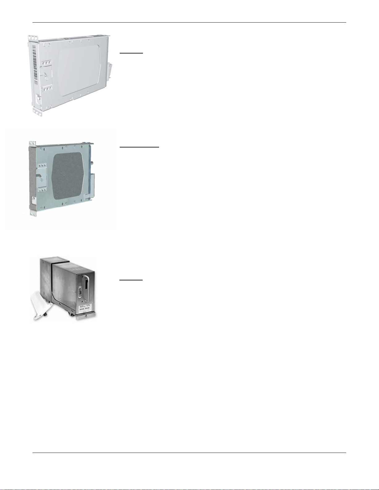
1.2 LRU Descriptions
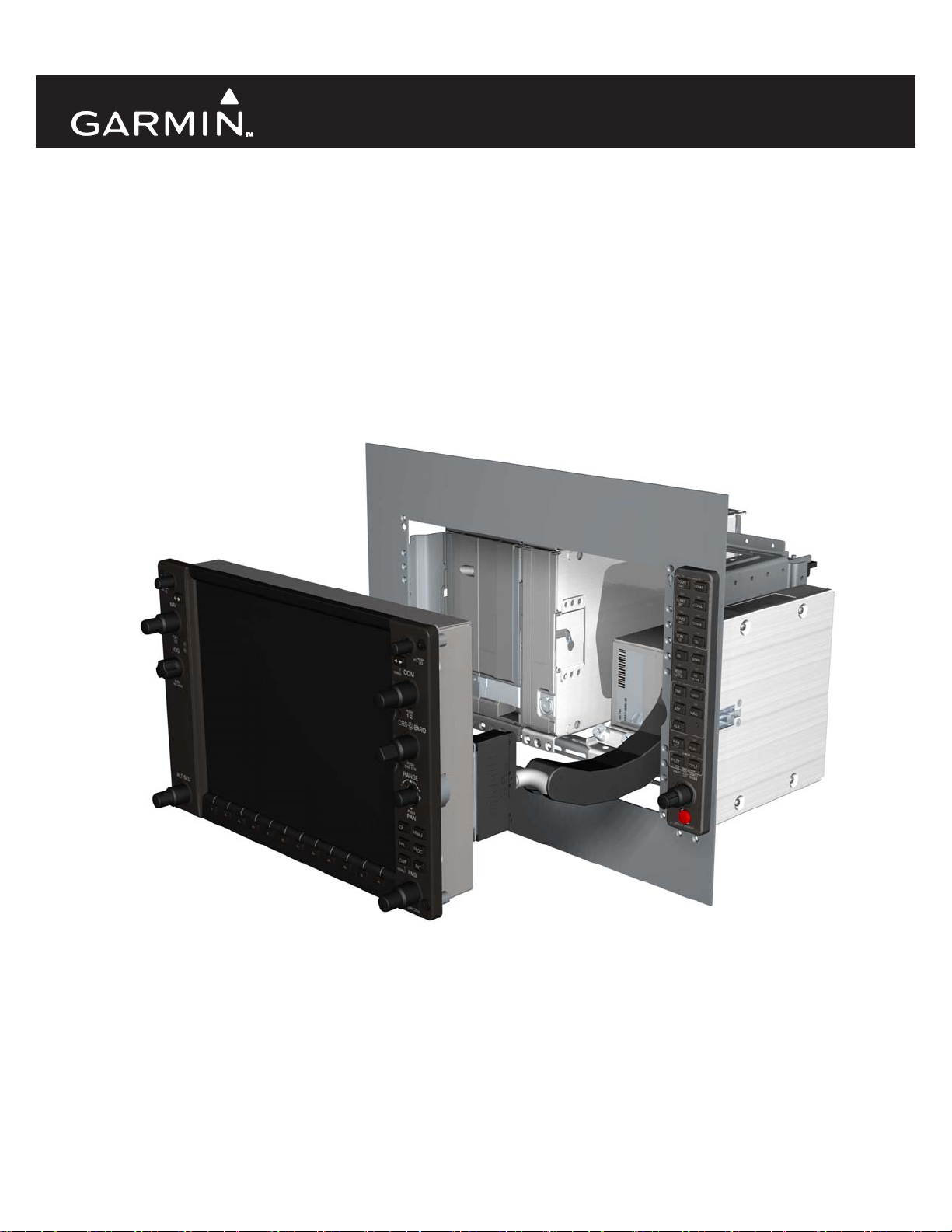
GDU 1040/1044B: The GDU 104X display is the most visible portion of the
G1000 system. The GDU 104X has a 10.4-inch LCD display with 1024 x 768
resolution. One is configured as a Primary Flight Display or PFD, the other is
configured as the Multi-Function Display or MFD. The MFD shows navigation
information and engine/airframe instrumentation. The PFD shows primary flight
information, in place of traditional gyro systems. Both GDU 104Xs link and
display all functions of the G1000 system during flight. The displays
communicate with each other and the GIA 63/63W units through a High-Speed
Data Bus (HSDB) Ethernet connection. The GDU 1044B provides autopilot
controls.
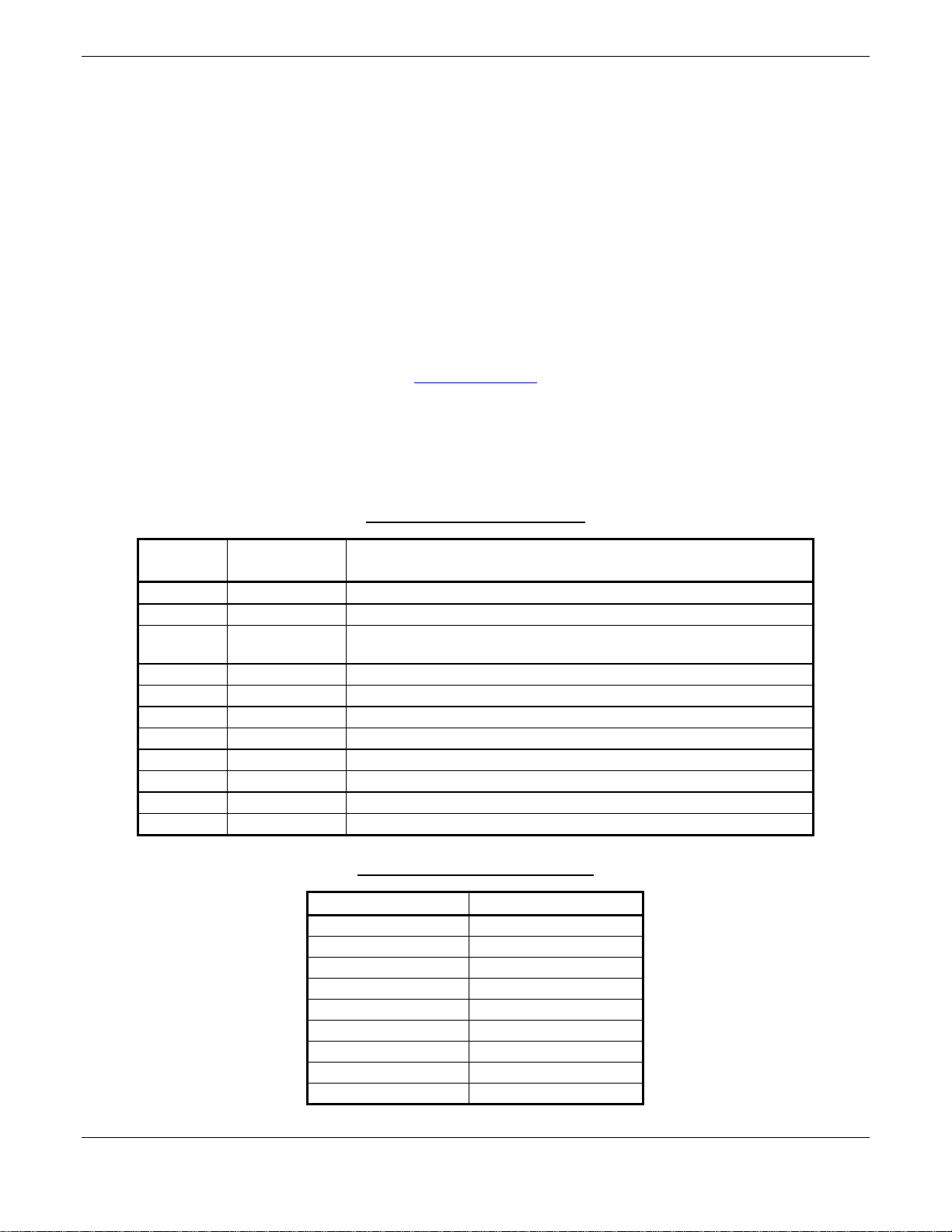
GMA 1347:
The GMA 1347 integrates NAV/COM digital audio, intercom
system and marker beacon controls. Manual display reversion is also controlled
by the GMA 1347. The GMA 1347 is normally installed between the MFD and
PFD. The GMA 1347 can also be installed in dual-audio panel applications
(usually paired with a dual-PFD setup). The GMA 1347 communicates with
both GIAs using RS-232 digital interface. Software and configuration settings
are received through RS-232 digital interface with the GIA.
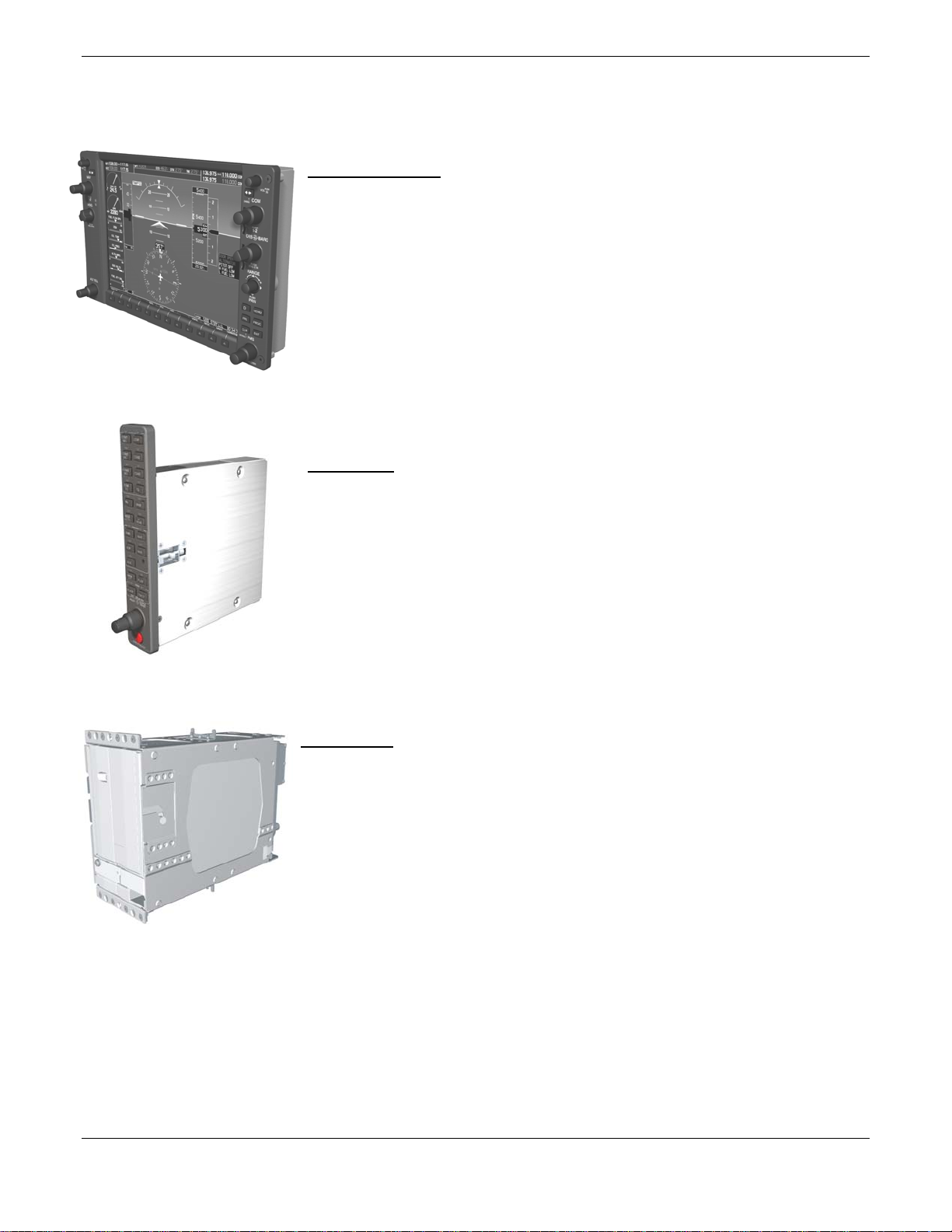
GIA 63/63W
: The GIA is the central ‘Integrated Avionics Unit’ (IAU) to the
G1000 system. The GIA functions as a main communications hub, linking all
LRUs with the PFD and MFD displays. The GIA contains the GPS receiver, VHF
COM/NAV receivers, and system integration microprocessors. The GIA
communicates directly with the GDU 104X displays using a HSDB Ethernet
connection. Software and configuration settings are sent from the displays
through the GIA to LRUs in the system. The GIA 63W contains a WAAS
certified GPS receiver.
Page 1-2 G1000 Nav III Line Maintenance Manual
Rev. L 190-00352-00
GRS 77: The GRS 77 is an attitude, heading, and reference, or AHRS, unit that
provides aircraft attitude and flight characteristics information to the G1000
displays and GIAs. The unit contains advanced tilt sensors, accelerometers, and
rate sensors. In addition, the GRS 77 interfaces with both the GDC 74A Air Data
computer and the GMU 44 magnetometer. The GRS 77 also utilizes GPS signals
sent from the GIA. Actual attitude and heading information is sent using ARINC
429 digital interface to both GDU 104Xs and GIAs.
GMU 44: The GMU 44 magnetometer senses magnetic field information. Data is
sent to the GRS 77 ARHS for processing to determine aircraft magnetic heading.
This unit receives power directly from the GRS 77 and communicates with the
GRS 77 using RS-485 digital interface.
GDC 74A: The GDC 74A air data computer compiles information from the
pitot/static system and various outside air temperature (OAT) and angle of attack
(AOA) sensors. The GDC 74A is responsible to provide pressure altitude,
airspeed, vertical speed, and OAT information to the G1000 system. The GDC
74A communicates with the GIA 63/GIA 63W, GDU 104X, and GRS 77 using
ARINC 429 digital interface. Software and configuration settings are received
through RS-232 digital interface with the GIA 63/GIA 63W.
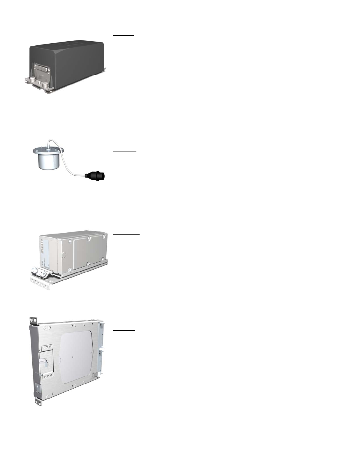
GEA 71
: The GEA 71 is a microprocessor-based LRU that is responsible for
receiving/processing signals from engine and airframe sensors. Sensor examples
include engine temperature and pressure sensors as well as fuel measurement and
pressure sensors. The GEA 71 communicates directly with both GIAs using RS485 digital interface. The GEA 71 can serve aircraft from basic single-engine
platforms to sophisticated turbine propulsion systems. Software and configuration
settings are received through RS-232 digital interface with the GIA.
G1000 Nav III Line Maintenance Manual Page 1-3
190-00352-00 Rev. L
GTX 33
: Solid-state Mode-S transponder. Provides Modes A, C, and S functions.
Control and operation is directed through the PFD. The transponder
communicates with both GIAs through RS-232 digital interface. Software and
configuration settings are received through RS-232 digital interface with the GIA.
GDL 69/69A:
The GDL 69/69A is an XM Satellite Radio data link receiver that
receives broadcast weather data. The GDL 69A is the same as the GDL 69 with
the addition of XM Satellite Radio audio entertainment. Weather data and control
of audio channel and volume is displayed on the GDU 104X MFD, via a HighSpeed Data Bus (HSDB) Ethernet connection. The GDL 69A is also interfaced to
the GMA 1347 Audio Panel for amplification and distribution of the audio signal.
GDL 90
The GDL 90 is a remote-mounted product that contains a GPS/WAAS
receiver and a Universal Access Transceiver. The GDL 90 will transmit
“ownship” data via the UAT data link. It will receive data from other UATequipped aircraft as well as FIS-B weather – the received data may be output to an
appropriate display.
Page 1-4 G1000 Nav III Line Maintenance Manual
Rev. L 190-00352-00

GSA 81 & GSM 85:
The GSA 81 servo actuator is an electromechanical LRU
that provides automatic control of pitch, roll, and pitch trim. It also provides
manual electric trim functionality. The GSA 81 contains a motor-control and
monitor circuit board, as well as a solenoid and a brushless DC motor. The GSA
81 receives serial RS-485 data packets from the GIA 63Ws.
The GSM 85 servo mount is mounted to the aircraft structure, via a custom
mounting bracket, and is responsible for transferring the output torque of the
GSA 81 servo actuator to the mechanical flight-control surface linkage.
GTP 59:
The GTP 59 OAT Probe provides outside air temperature measurement
which is used by the GDC 74A. Communication interface to the G1000 is
through the GDC 74A.
G1000 Nav III Line Maintenance Manual Page 1-5
190-00352-00 Rev. L

1.3 G1000 Block Diagrams
1.3.1 Typical System Interconnect
Figure 1-1 shows a typical Cessna Nav III G1000 system interconnect.
Figure 1-1. Typical Cessna Nav III G1000 System Interconnect
Page 1-6 G1000 Nav III Line Maintenance Manual
Rev. L 190-00352-00
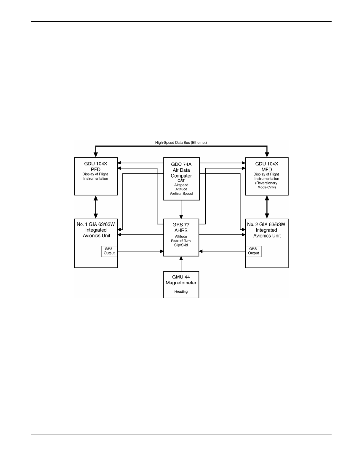
1.3.2 Flight Instrumentation
The GRS 77 AHRS, GDC 74A Air Data Computer, and GMU 44 Magnetometer are responsible for providing the
G1000 system with flight instrumentation. Data consist of aircraft attitude, heading, altitude, airspeed, vertical
speed, and outside air temperature information, all displayed on the PFD (data is displayed on the MFD in
reversionary mode).
Primary data outputs from the GRS and GDC are sent directly to the PFD via ARINC 429. Secondary data paths
connect the GRS to the MFD. Additional communications paths connect the GRS and GDC to both GIA units,
providing quadruple redundant interface.
The GRS 77 receives GPS data from both GIAs, airspeed data from the GDC, and magnetic heading from the
GMU. Using these three external sources, combined with internal sensor data, the GRS accurately calculates
aircraft attitude and heading.
Figure 1-2. G1000 Flight Instrumentation Data Paths
G1000 Nav III Line Maintenance Manual Page 1-7
190-00352-00 Rev. L
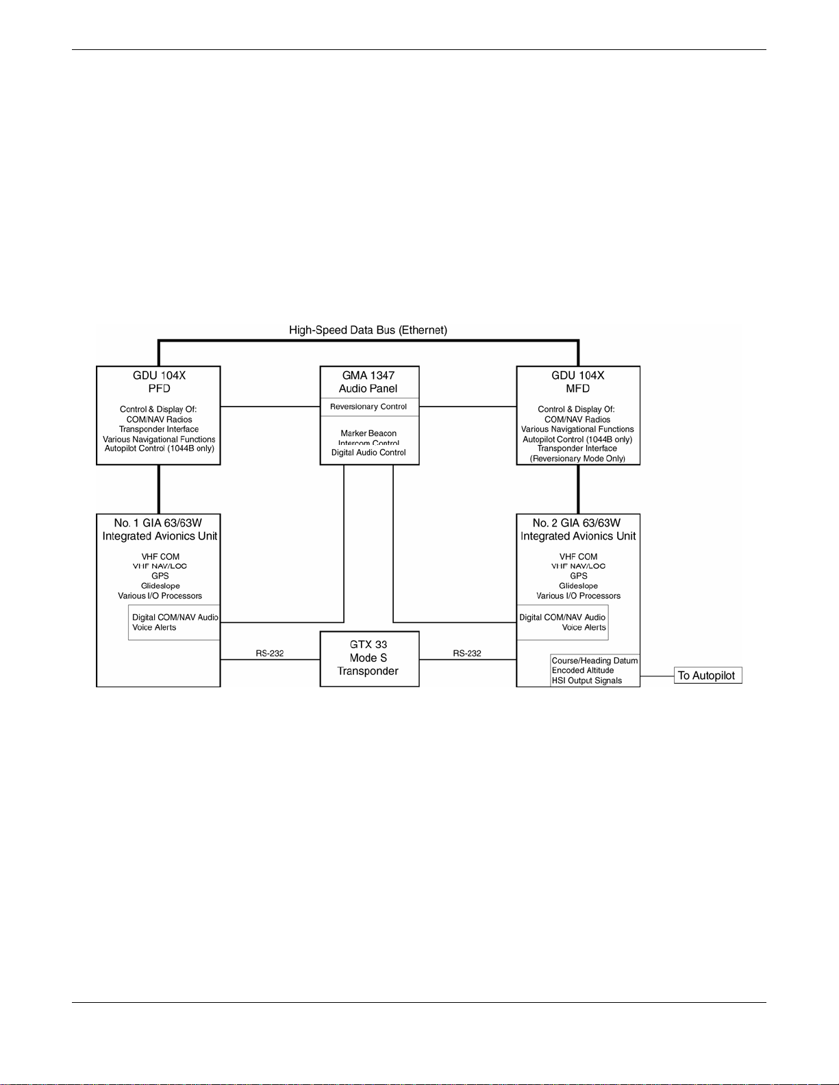
1.3.3 Navigation/Communication Systems
The GIAs contain VHF COM, VHF NAV, and GPS receivers. COM and NAV audio is sent via digital audio to
the GMA 1347 Audio Panel.
GPS information is sent to the GRS 77 AHRS and both displays for processing.
The GTX 33 Mode S Transponder communicates with both GIAs. Transponder data is sent from the GIAs to the
PFD.
The #2 GIA outputs analog HSI signals to the KAP 140 autopilot, if equipped. In the case of the GFC 700 both of
the GIAs communicate to the servos through RS-485, see Figure 1-1.
The GMA 1347 Audio Panel controls audio selections and the display reversionary mode.
Figure 1-3. G1000 Navigation/Communication Data Paths
Page 1-8 G1000 Nav III Line Maintenance Manual
Rev. L 190-00352-00
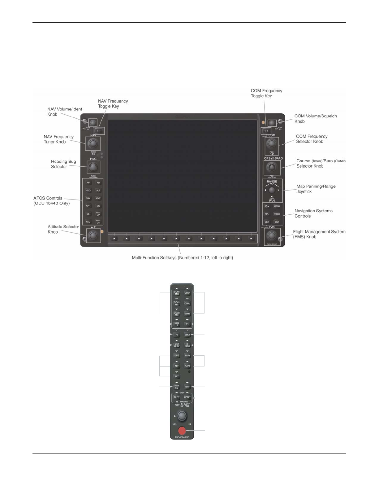
1.4 User Interface
1.4.1 Control & Operation
All control and operation of G1000 equipment as normally used in flight occurs through the PFD, MFD or
GMA 1347 audio panel. Figure 1-4 identifies various GDU 104X buttons. See the appropriate G1000 Nav III
Cockpit Reference Guide, as well as the appropriate AFMS for more detail on control and operation of the
G1000.
Figure 1-4. GDU 104X Control Interface
1.4.2 GMA 1347 Control
Transmitters
Split COM
Passenger Address
Marker Beacon/Mute
Navigation Radio Audio
Manual Squelch
Volume/Squelch
Control
Transceiver Audio
Cellular Telephone
Speaker
Marker Beacon Signal Sensitivity
Navigation Radio Audio
Digital Recording Playback
ICS Isolation
Display Backup
Reversionary Button
Figure 1-5. GMA 1347 Control Interface
G1000 Nav III Line Maintenance Manual Page 1-9
190-00352-00 Rev. L
1.4.3 Configuration Mode Operation
The configuration mode exists to provide the installer or technician with a means of configuring, checking, and
calibrating various G1000 sub-systems. Troubleshooting/diagnostics information can also be derived from this
mode.
To start the system in Configuration Mode:
1. Press and hold the ENT key on the PFD while applying power.
2. Release the ENT key after ‘INITIALIZING SYSTEM’ appears in the upper left corner of the PFD.
3. Power on the MFD in the same manner. It is best to have both displays in the same mode.
NOTE
Configuration settings for each G1000 LRU must be adjusted on the PFD.
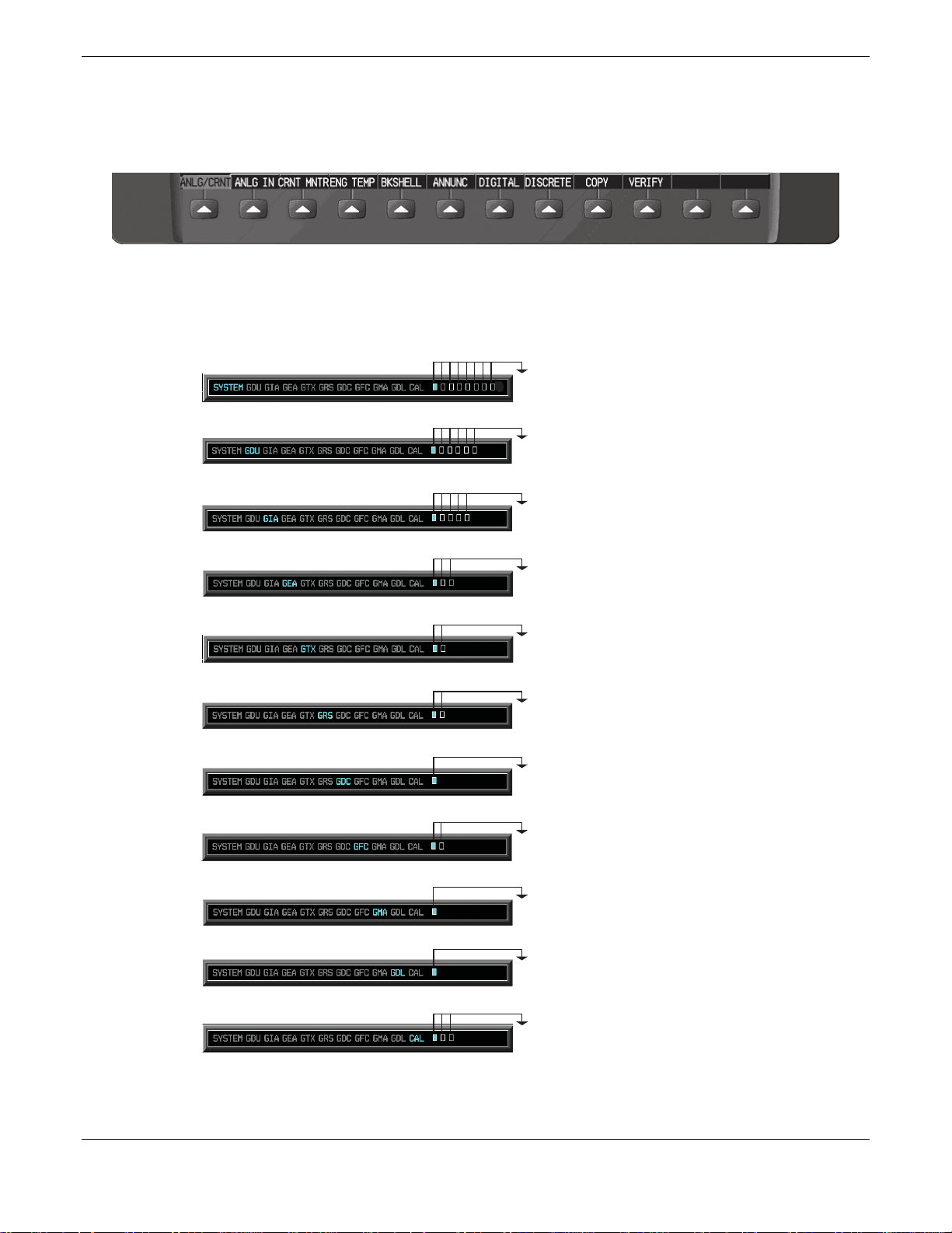
1.4.4 FMS Cursor
The FMS knob is the primary control for the G1000 system. Operation is similar to the Garmin 400/500 Series
units.
• To cycle through different configuration screens:
To change page groups:
To change pages in a group:
• To activate the cursor for a page, press the small FMS knob directly in, as one would push a regular
button.
• To cycle the cursor through different data fields, rotate the large FMS knob.
• To change the contents of a highlighted data field, rotate the small FMS knob. This action either brings
up an options menu for the particular field, or in some cases allows the operator to enter data for the field.
• To confirm a selection, press the ENT key.
• To cancel a selection, press the small FMS knob. Pressing the small FMS knob again, deactivates the
cursor. The CLR key may also be used to cancel a selection or deactivate the cursor.
Rotate the large FMS knob.
Rotate the small FMS knob.
Figure 1-6. FMS Control Knob
Page 1-10 G1000 Nav III Line Maintenance Manual
Rev. L 190-00352-00
1.4.5 Softkeys
Some configuration pages have commands or selections that are activated by the GDU 104X softkeys. If a
softkey is associated with a command, that command will be displayed directly above the key. A grayed-out
softkey shows a command that is unavailable. A softkey that is highlighted shows the current active selection.
Figure 1-7. G1000 Softkeys
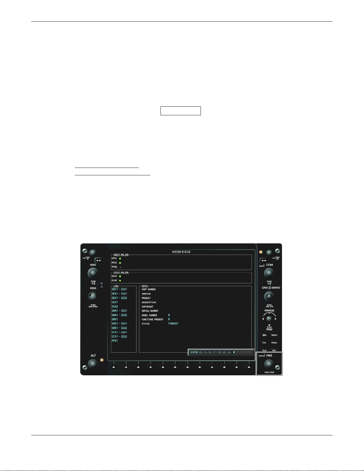
1.4.6 Configuration Mode Overview
The following diagram shows the layout and organization of various configuration mode page groups and pages.
1. System Status Page
2. Date/Time Setup page
3. Main Lighting Page
4. Audio Alert Configuration Page
5. Software Upload Page
1. RS-232 / ARINC 429 Config Page
2. GDU Status Page
3. GDU Test Page
4. Serial/Ethernet I/O Page
5. Alert Configuration Page
1. RS-232 / ARINC 429 Config Page
2. CAN / RS-485 Configuration Page
3. GIA I/O Configuration Page
4. COM Setup Page
5. GIA Status Page
1. Engine Data Page
2. GEA Status Page
3. GEA Configuration Page
1. RS-232 / ARINC 429 Config Page
2. Transponder Configuration Page
6. Configuration Upload Page
7. System Configuration Page
8. Manifest Configuration Page
6. Airframe Configuration Page
1. AHRS / Air Data Input Page
2. GRS / GMU Calibration Page
1. GDC Configuration Page
1. GFC Configuration Page
2. GFC STATUS Page
1. GMA Configuration Page
1. GDL Page
1. FUEL CALIBRATION Page
2. FUEL TANK CONFIGURATION Page
3. FLAPS AND TRIM CALIBRATION Page
Figure 1-8. Configuration Mode Navigation
G1000 Nav III Line Maintenance Manual Page 1-11
190-00352-00 Rev. L

1.4.7 Data Transmission Indicators
Several configuration screens utilize indicator light to show data and/or component status. Unless otherwise
noted, the following applies to all such indicators:
• Green Light: Expected discrete data is successfully received and true, or status is good.
• Red Light: Expected discrete data is not received or is invalid, or status is bad.
• No Light (Black): No discrete data is expected, or it is received successfully and off, or status is not
received or is invalid.
1.4.8 Configuration Page Protection
The configuration mode contains pages that display various settings that are critical to aircraft operation and
safety. At these pages, the technician is unable to modify or change settings unless they are authorized and
equipped to do so. However, most protected pages are viewable to allow technicians greater system awareness
for troubleshooting.
1.4.9 G1000 Loader Card Interface
The G1000 Loader Card interface exists to provide a means of loading software and configuration files to the
system. The G1000 Loader Card uses a 128 MB Secure Digital (SD) data card that contains all necessary files to
load software and configuration settings to all G1000 LRUs.
Nearly all software and configuration parameters are pre-determined by Garmin and/or Cessna. During removal
and replacement of LRUs, software and configuration files may need to be reloaded. To satisfy TC/STC
requirements for a specific aircraft, it is critical that the technician use the correct G1000 Loader Card part
number. Each Loader Card’s part number defines all files found on the card for a specific G1000 installation.
Note that certain configuration settings, such as aircraft registration number (‘N#’) must be entered manually. A
sample procedure for loading software and configuration settings can be found in Section 4 of this manual.
CAUTION
Always use caution when using G1000 Software Loader Cards during maintenance. The G1000
system is designed to immediately initialize the card upon power-up. On-screen prompts must be
given careful attention in order to avoid potential loss of data. Always read and thoroughly
understand all related information before attempting to use the G1000 Software Loader Cards.
Page 1-12 G1000 Nav III Line Maintenance Manual
Rev. L 190-00352-00

1.4.10 Configuration Files
A G1000 Loader Card typically contains the following configuration files:
• AIRFRAME: This file contains data such as airspeed parameters, engine/airframe sensor limitations,
fuel tank parameters and alerting system settings that tailor a G1000 PFD or MFD to a specific
airframe.
• SYSTEM: This file configures the G1000 Ethernet to communicate with a PFD, MFD, and GIAs.
• MANIFEST: This file loads a manifest of all software part numbers and versions associated with an
approved system configuration.
• MFD1: This file configures the MFD serial/discrete communications and alerting system settings.
• PFD1: This file configures the PFD serial/discrete communications and alerting system settings.
• GIA1/GIA2: These files configure GIA1 and GIA 2 serial/discrete communications settings.
• GMA1: This file configures the GMA 1347 audio and serial communications settings.
• GTX1: This file configures the GTX transponder and serial communications settings.
• GEA1: This file configures GEA 71 engine/airframe parameters.
• GDC1: This file configures the GDC 74A air data values.
• GDL69: This file configures the GDL 69A serial communications settings
• CALIBRATION: This file configures calibration values for various analog sensors connected to the
GEA (fuel quantity, fuel flow, etc.)
• AUDIO: This file configures all of the audio messages for the G1000 system. This includes both
tones and voice messages that are utilized for alerts, cautions, and warnings.
The above files are loaded during the configuration process. Each file is sent directly to the applicable LRU. The
same file is also stored into PFD internal configuration memory and configuration module. If the PFD is
replaced, the configuration module retains all configuration files in the aircraft.
NOTE
The GRS 77 AHRS and GMU 44 Magnetometer do not utilize a configuration file. However,
these LRUs do require several calibrations during installation and/or maintenance.
G1000 Nav III Line Maintenance Manual Page 1-13
190-00352-00 Rev. L
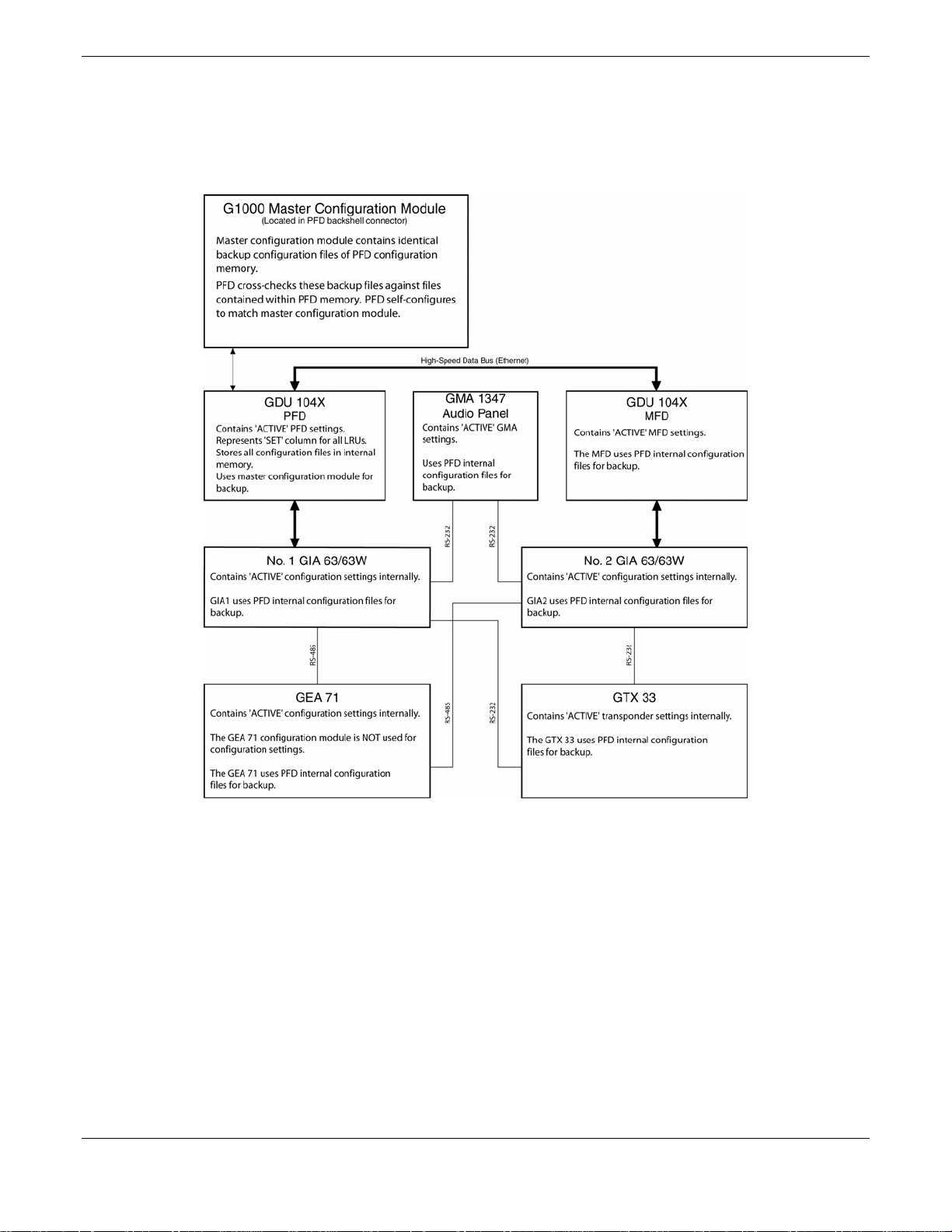
1.4.11 Configuration File Retention
The G1000 system is designed to store all configuration settings in various places so that the configuration of the
system is retained in the aircraft during maintenance. Since the G1000 Integrated Flight Deck is installed in a
variety of aircraft, it is imperative that aircraft-specific data be retained at the aircraft level. Figures 1-9 and 1-10
show a block diagram of how a typical G1000 system stores configuration settings.
Figure 1-9. G1000 Configuration Storage
Page 1-14 G1000 Nav III Line Maintenance Manual
Rev. L 190-00352-00
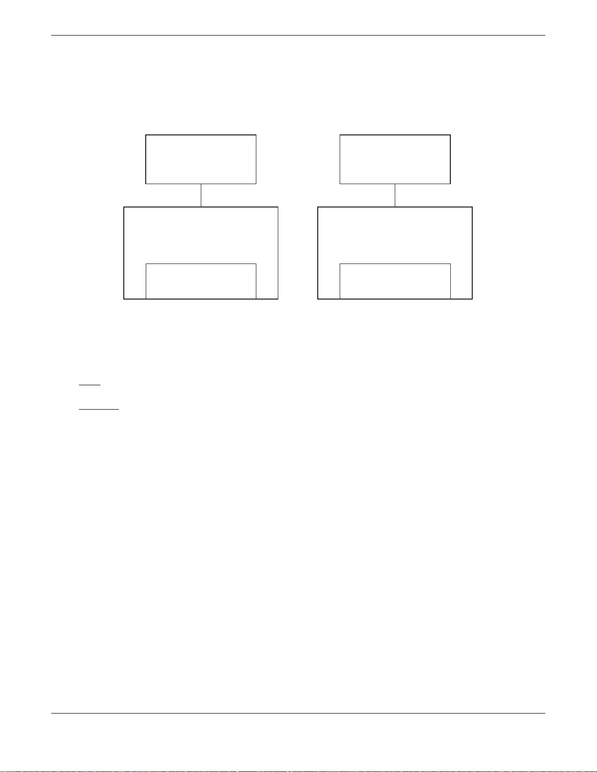
The GRS 77 and GDC 74A configuration modules function differently than the rest of the system. The
GDC 74A’s configuration file is loaded directly to GDC internal memory, a copy is also stored in the GDC
configuration module.
The GRS 77 configuration module stores calibration data recorded during installation calibration procedures, and
does not store configuration settings.
GRS 77 Config Module
(Located in GRS backshell connector)
Stores a copy of AHRS/Magnetometer calibration
values that are recorded upon completion of
post-installation calibration procedures.
GDC 74A Config Module
(Located in GDC backshell connector)
Stores a copy of the GDC 74A configuration file.
GRS 77
The GRS 77 stores calibration data internally.
The GRS 77 also stores factory calibration data internally.
Should internal memory or the configuration module fail,
AHRS ouput data flags invalid.
Contains internal sensor calibration data that is
not installation-specific. Data is stored from
factory calibrations.
AHRS
GRS Internal Memory
The GDC 74A stores the GDC1 configuration file internally.
The GDC 74A also stores factory calibration data internally.
Should internal memory or the configuration module
fail, loss of some or all airdata outputs will result.
Contains internal sensor calibration data that is
not installation-specific. Data is stored from
factory calibrations.
GDC 74A
Air Data Computer
GDC Internal Memory
Figure 1-10. GRS/GDC Configuration Storage
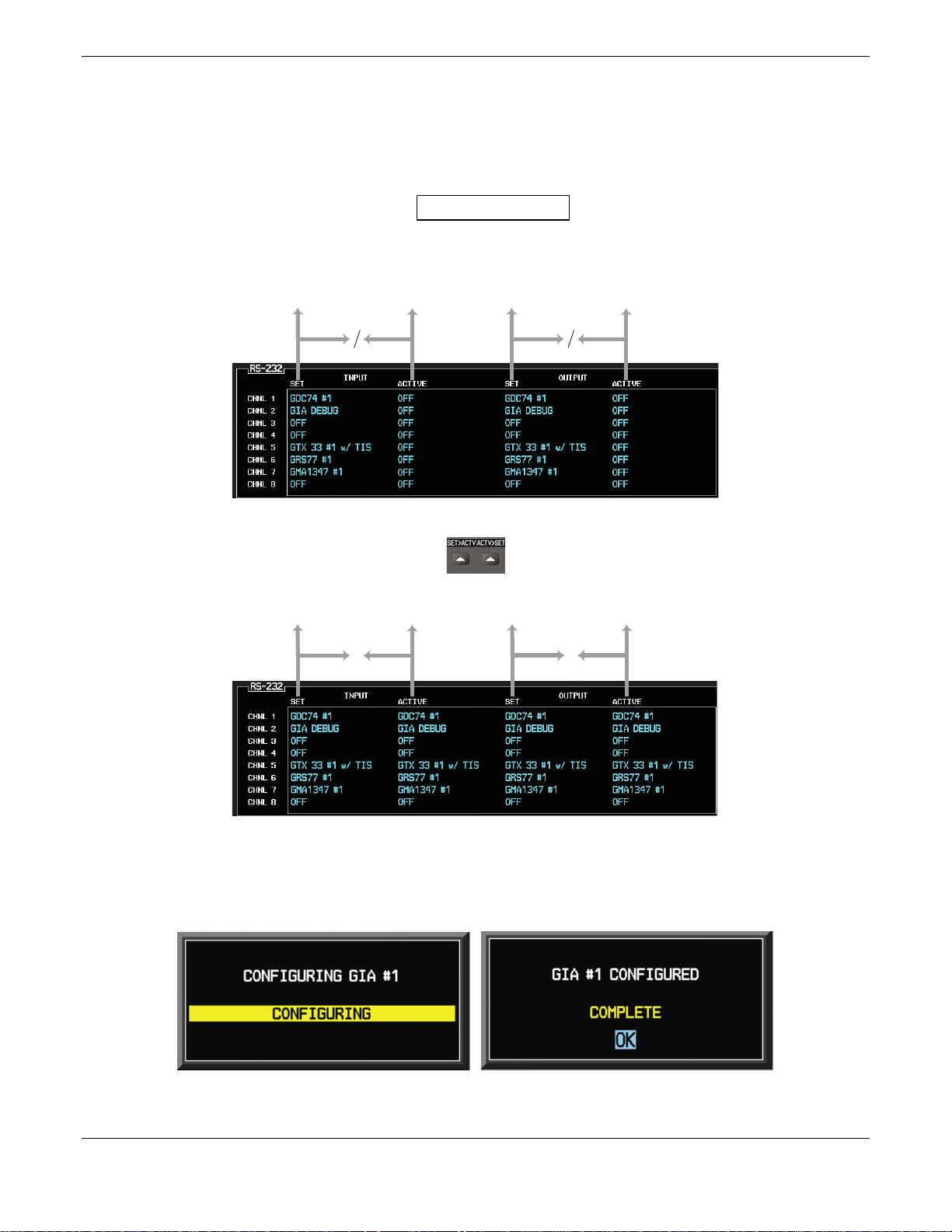
1.4.12 SET>ACTV / ACTV>SET
Throughout various configuration mode pages, there are SET and ACTIVE columns for input/output settings and
other parameters.
Refers to a setting or group of settings that reside in the PFD’s internal memory and/or master
SET:
configuration module (See Figure 1-11).
ACTIVE:
Refers to a current setting stored and used in a LRU. LRUs store the ‘active’ settings within
internal memory.
Data can be manually copied from one column to the other by using the following two softkeys:
• SET>ACTV (read ‘Set to Active’) softkey: Allows the installer to send the information in the SET
column (data stored in the master configuration module) to the ACTV column (data used by LRU).
• ACTV>SET (read ‘Active to Set’) softkey: Causes the LRUs current settings to be copied to the master
configuration module as SET items.
In the first example shown in Figure 1-11, the SET columns do not match the ACTIVE columns. The inequality
between SET and ACTIVE indicates a configuration mismatch. By pressing the SET>ACTV softkey, this copies
the SET column to the LRU unit’s configuration memory. The settings then become the ACTIVE settings for the
LRU being configured.
G1000 Nav III Line Maintenance Manual Page 1-15
190-00352-00 Rev. L
Configuration Mismatch
1.4.13 ACTV>SET Interface
The only time ACTV>SET should be used is when the master configuration module fails and must be replaced.
In this circumstance the ACTV>SET softkey may be used to reload correct configuration settings from previously
installed LRUs. Should a LRU be replaced along with the master configuration module, the LRU needs to be
reconfigured using the G1000 SW Loader Card.
WARNING
The ACTV>SET softkey must be used with caution! If an improperly configured unit is
installed, this softkey causes the wrong configuration to replace the correct aircraft configuration!
Master Configuration Module
Master Configuration Module
LRU Memory
=
Master Configuration Module
=
SET>ACTV Softkey
Configuration Correct
LRU Memory
Master Configuration Module
= =
LRU Memory
LRU Memory
Figure 1-11. SET/ACTV Feature
In most cases, when a setting is changed, the newer setting will automatically be transferred to the appropriate
LRU. The technician receives on-screen confirmation that the configuration is successful, as depicted in
Figure 1-12. Likewise, if a configuration error is detected, it too is shown in similar fashion.
Figure 1-12. Configuration Status
Page 1-16 G1000 Nav III Line Maintenance Manual
Rev. L 190-00352-00

1.5 Recommended Tools
The following tools are needed to perform various maintenance tasks on G1000 equipment:
• Voltmeter capable of measuring 0-32 Volts DC
• #2 Phillips Screwdriver
nd
• 3/32
• Digital Level with 0.25 degrees of accuracy capability
• VHF NAV/COM/ILS ramp tester
• Transponder ramp tester including Mode S capability for Mode S transponder equipped aircraft
• Air Data Test Set (ADTS) capable of simulating altitude up to the aircraft’s service ceiling
• GPS indoor repeater (if outside GPS signals cannot be acquired)
• Headset/Microphone
inch Hex Tool
G1000 Nav III Line Maintenance Manual Page 1-17
190-00352-00 Rev. L

Blank Page
Page 1-18 G1000 Nav III Line Maintenance Manual
Rev. L 190-00352-00
2 TROUBLESHOOTING
Begin troubleshooting by determining the specific failure. Follow guidance for the appropriate LRU provided in
this section. Reference applicable aircraft manufacturer provided wiring diagrams as an aid in troubleshooting.
NOTE
See Section 3 for instructions on removing and replacing. Once an LRU is replaced, a software
update and configuration may be required. See Section 4 for instructions on configuration and
uploading software.
NOTE
If PFD1, MFD1, GIA1 or GIA2 configuration files are loaded during troubleshooting, any
optional equipment files for equipment installed in the aircraft must also be loaded. Failure to
reload the optional configuration files may deactivate the equipment. Be sure to note any
optional equipment installed (by pre-inspection or by logbook entry) before loading PFD/MFD
and/or GIA 1/2 configuration files.
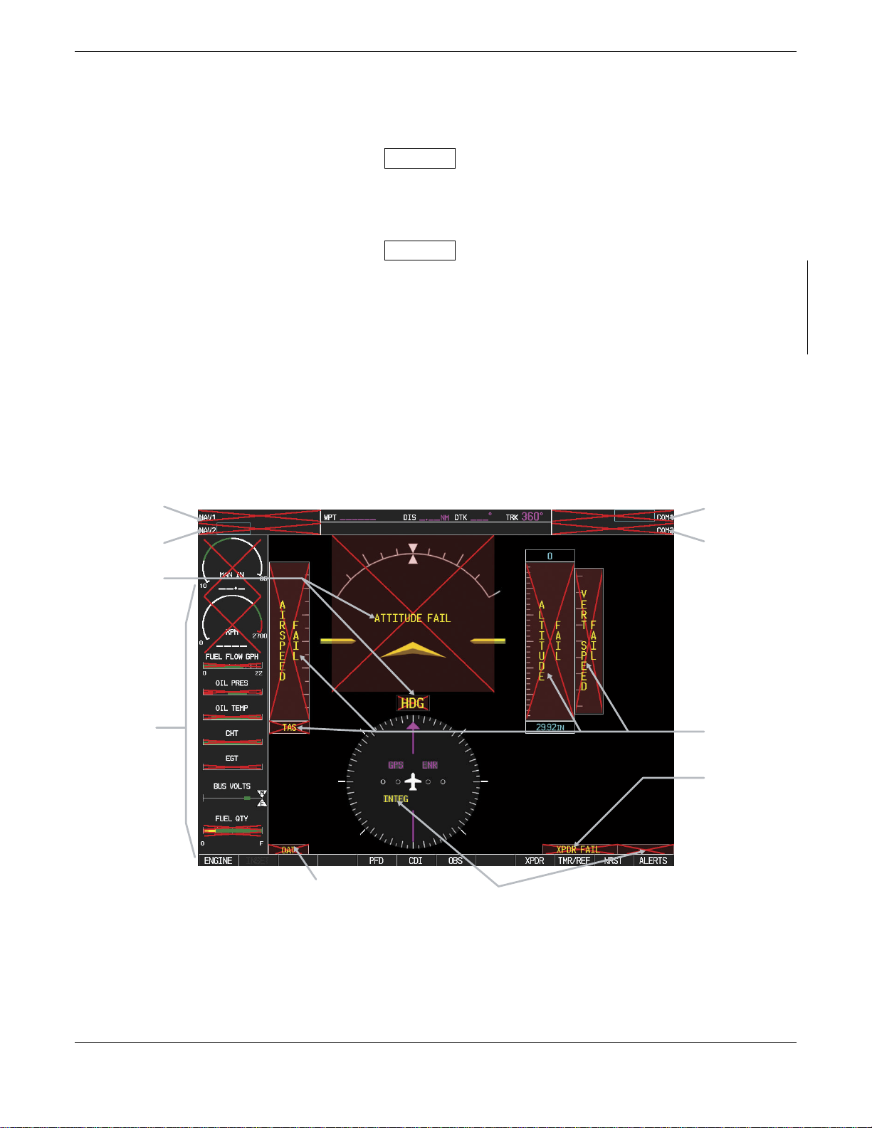
2.1 G1000 Alerting System
2.1.1 System Annunciations
A red X through a display field; such as Com frequencies, Nav frequencies, or engine data, indicates that display
field is not receiving valid data. Figure 2-1 shows display fields that are not receiving valid data and their
associated LRUs. See Section 2.1.1.1 for information on troubleshooting system annunciations.
No. 1 GIA 63
No. 1 GIA 63
No. 2 GIA 63
Attitude: GRS 77 AHRS
Heading: GRS 77 or GMU 44
No. 1 & 2 GIA 63
or GEA 71
or Equivalent
Engine/Airframe
Sensors
GTP 59 OAT Probe
or GDC 74A ADC
GIA 63 No. 1, 2
Figure 2-1. Red X’d Display Fields
No. 2 GIA 63
GDC 74A
Air Data Computer
GTX 33 Transponder or
#1 & 2 GIA 63
G1000 Nav III Line Maintenance Manual Page 2-1
190-00352-00 Rev. L
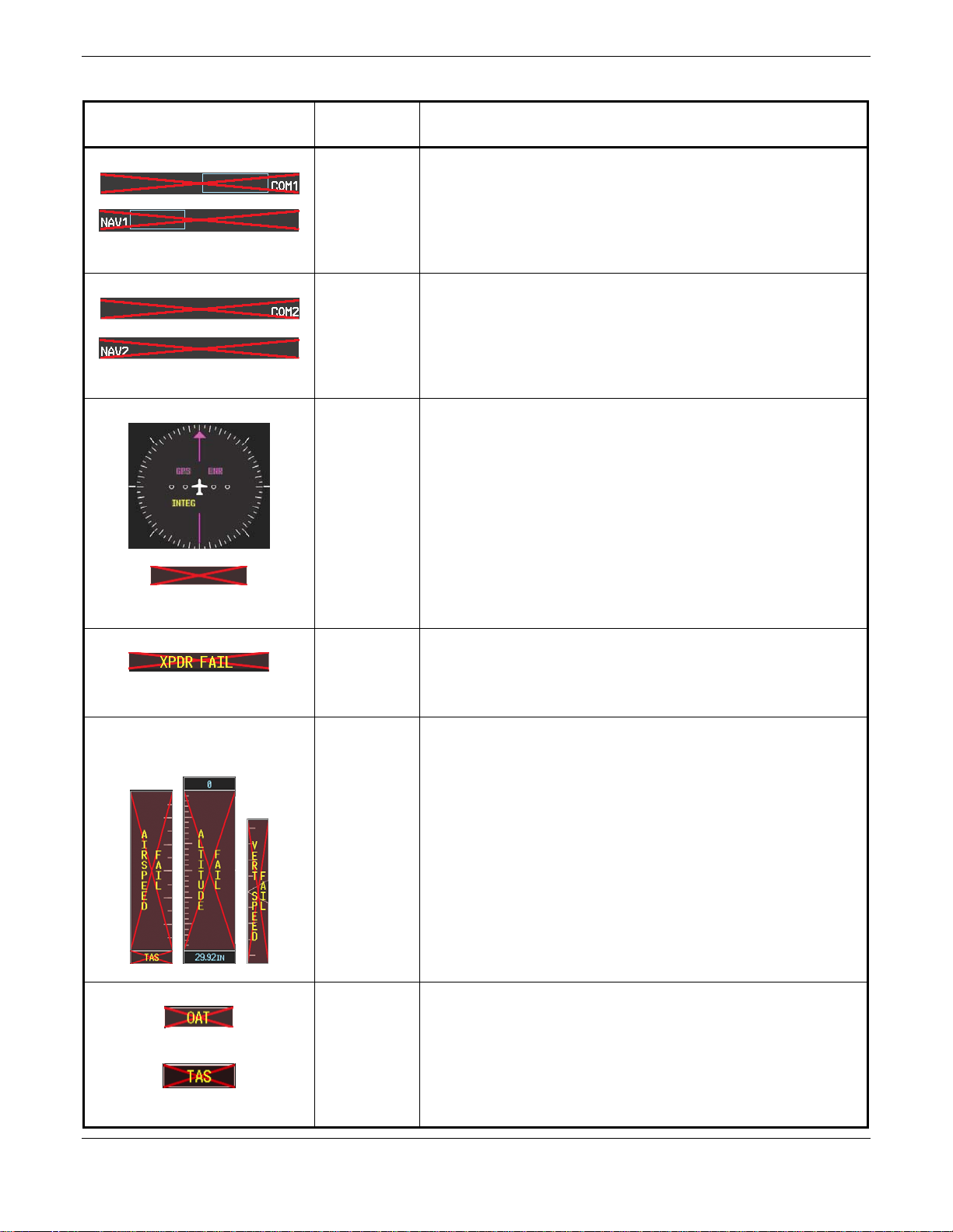
2.1.1.1 System Annunciation Troubleshooting
Annunciation
NAV1 or COM1
NAV2 or COM2
GPS INTEG or Time
XPDR FAIL
TAS, AIRSPEED FAIL,
ALTITUDE FAIL,
VERT SPEED FAIL
Associated
Solution
LRU
• Check configuration settings for GIA1 and the PFD
GIA1
• Check Ethernet interconnect from GIA1 to the PFD
• Switch GIA1 and GIA2, to verify location of problem:
o If problem follows GIA1, replace GIA1.
o If problem persists, replace PFD.
• Check configuration settings for GIA2 and the MFD
GIA2
• Check Ethernet interconnect from GIA2 to the MFD
• Switch GIA1 and GIA2, to verify location of problem:
o If problem follows GIA2, replace the GIA2.
o If problem persists, replace MFD.
• Ensure that a cell phone or a device using cell phone
technology is not turned on (even in a monitoring state) in
the cabin.
• Check GPS1 and GPS2 signal strength on AUX page 3
• Check corresponding GPS antenna and cable
GIA1 or 2
• Check Ethernet interconnect between the PFD and GIA1
or MFD and GIA2 for faults.
• Switch GIA1 and GIA2, to verify location of problem:
o If problem follows the GIA, replace the GIA.
o If problem persists, replace the MFD or PFD.
• Check GTX 33 configuration settings for GIA1 and GIA2
GTX 33
• Perform a SET>ACTV configuration reset on the GTX
Config page, and verify the aircraft registration is present.
• Replace the GTX 33
• Inspect GDC 74A pitot/static plumbing integrity.
• Inspect pitot/static ports and associated equipment.
• For TAS failure, also check GTP 59 probe.
GDC 74A
• Check GDC 74A configuration settings for the PFD, MFD,
GIA1, and GIA2
o If PFD, MFD, and GIA configuration settings are
correct, replace the GDC configuration module.
o If problem persists, replace the GDC 74A
OAT
and
TAS
GTP 59
• Check OAT probe wiring and connectors for faults.
• Check GDC config module wiring for damage, replace if
any is found.
• Replace GDC config module
• Replace GDC 74A with a known good unit:
o If problem persists, replace the GTP 59.
Page 2-2 G1000 Nav III Line Maintenance Manual
Rev. L 190-00352-00
 Loading...