

Page 1

G1000H
Cockpit Reference Guide for the Bell 407GX
™
Integrated Flight Deck
Page 2

Page 3

FLIGHT INSTRUMENTS
EICAS
NAV/COM/TRANSPONDER/AUDIO PANEL
AUTOMATIC FLIGHT CONTROL SYSTEM
GPS NAVIGATION
FLIGHT PLANNING
PROCEDURES
HAZARD AVOIDANCE
ADDITIONAL FEATURES
ABNORMAL OPERATION
ANNUNCIATIONS & ALERTS
APPENDIX
INDEX
Page 4

Page 5

Copyright © 2011 Garmin Ltd. or its subsidiaries. All rights reserved.
This manual reflects the operation of System Software 1237.03 or later for the Bell 407GX.
Some differences in operation may be observed when comparing the information in this manual
to earlier or later software versions.
Garmin International, Inc., 1200 East 151st Street, Olathe, Kansas 66062, U.S.A.
Tel: 913/397.8200 Fax: 913/397.8282
Garmin AT, Inc., 2345 Turner Road SE, Salem, OR 97302, U.S.A.
Tel: 503/391.3411 Fax 503/364.2138
Garmin (Europe) Ltd, Liberty House, Bulls Copse Road, Hounsdown Business Park,
Southampton, SO40 9RB, U.K.
Tel: 44/0870.8501241 Fax: 44/0870.8501251
Garmin Corporation, No. 68, Jangshu 2nd Road, Shijr, Taipei County, Taiwan
Tel: 886/02.2642.9199 Fax: 886/02.2642.9099
For after-hours emergency, aircraft on ground (AOG) technical support for Garmin panel mount
and integrated avionics systems, please contact Garmin’s AOG Hotline at 913.397.0836.
Web Site Address: www.garmin.com
Except as expressly provided herein, no part of this manual may be reproduced, copied,
transmitted, disseminated, downloaded or stored in any storage medium, for any purpose
without the express written permission of Garmin. Garmin hereby grants permission to
download a single copy of this manual and of any revision to this manual onto a hard drive or
other electronic storage medium to be viewed for personal use, provided that such electronic
or printed copy of this manual or revision must contain the complete text of this copyright
notice and provided further that any unauthorized commercial distribution of this manual or any
revision hereto is strictly prohibited.
Garmin® and G1000H™ are registered trademarks of Garmin Ltd. or its subsidiaries. WATCH®,
FliteCharts®, and SafeTaxi® are trademarks of Garmin Ltd. or its subsidiaries. These trademarks
may not be used without the express permission of Garmin.
NavData® is a registered trademark of Jeppesen, Inc.; Stormscope® and SkyWatch® are
registered trademarks of L-3 Communications; and XM® is a registered trademark of SiriusXM
Satellite Radio, Inc.;
AOPA Membership Publications, Inc. and its related organizations (hereinafter collectively
“AOPA”) expressly disclaim all warranties, with respect to the AOPA information included in this
data, express or implied, including, but not limited to, the implied warranties of merchantability
and fitness for a particular purpose. The information is provided “as is” and AOPA does not
Page 6

warrant or make any representations regarding its accuracy, reliability, or otherwise. Under
no circumstances including negligence, shall AOPA be liable for any incidental, special or
consequential damages that result from the use or inability to use the software or related
documentation, even if AOPA or an AOPA authorized representative has been advised of the
possibility of such damages. User agrees not to sue AOPA and, to the maximum extent allowed
by law, to release and hold harmless AOPA from any causes of action, claims or losses related
to any actual or alleged inaccuracies in the information. Some jurisdictions do not allow the
limitation or exclusion of implied warranties or liability for incidental or consequential damages
so the above limitations or exclusions may not apply to you.
September, 2011 190-01254-00 Rev. B Printed in the U.S.A.
Page 7

Warnings, Cautions & Notes
WARNING: Navigation and terrain separation must NOT be predicated upon
the use of the terrain avoidance feature. The terrain avoidance feature is NOT
intended to be used as a primary reference for terrain avoidance and does
not relieve the pilot from the responsibility of being aware of surroundings
during flight. The terrain avoidance feature is only to be used as an aid for
terrain avoidance. Terrain data is obtained from third party sources. Garmin
is not able to independently verify the accuracy of the terrain data.
WARNING: The displayed minimum safe altitudes (MSAs) are only advisory
in nature and should not be relied upon as the sole source of obstacle and
terrain avoidance information. Always refer to current aeronautical charts
for appropriate minimum clearance altitudes.
WARNING: The altitude calculated by G1000H GPS receivers is geometric
height above Mean Sea Level and could vary significantly from the altitude
displayed by pressure altimeters, such as the GDC 74H Air Data Computer, or
other altimeters in the aircraft. GPS altitude should never be used for vertical
navigation. Always use pressure altitude displayed by the G1000H PFD or
other pressure altimeters in aircraft.
WARNING: Do not use outdated database information. Databases used in
the G1000H system must be updated regularly in order to ensure that the
information remains current. Pilots using any outdated database do so entirely
at their own risk.
WARNING: Do not use basemap (land and water data) information for
primary navigation. Basemap data is intended only to supplement other
approved navigation data sources and should be considered as an aid to
enhance situational awareness.
WARNING: Traffic information shown on the G1000H Multi Function Display
is provided as an aid in visually acquiring traffic. Pilots must maneuver
the aircraft based only upon ATC guidance or positive visual acquisition of
conflicting traffic.
WARNING: NEXRAD weather data is to be used for long-range planning
purposes only. Due to inherent delays in data transmission and the relative
age of the data, NEXRAD weather data should not be used for short-range
weather avoidance.
190-01254-00 Rev. B
Garmin G1000H™ Cockpit Reference Guide for the Bell 407GX
Page 8

Warnings, Cautions & Notes
WARNING: Do not use datalink weather products (e.g., XM WX Satellite
Weather, GFDS World Wide Weather, or FIS-B) for hazardous weather
penetration. Weather information provided by these products is aged by
up to several minutes and may not depict actual weather conditions as they
currently appear.
WARNING: Use of the Stormscope is not intended for hazardous weather
penetration (thunderstorm penetration). Stormscope information, as
displayed on the G1000H MFD, is to be used only for weather avoidance, not
penetration.
WARNING: The Garmin G1000H, as installed in the Bell 407GX rotorcraft, has
a very high degree of functional integrity. However, the pilot must recognize
that providing monitoring and/or self-test capability for all conceivable system
failures is not practical. Although unlikely, it may be possible for erroneous
operation to occur without a fault indication shown by the G1000H. It is
thus the responsibility of the pilot to detect such an occurrence by means of
cross-checking with all redundant or correlated information available in the
cockpit.
WARNING: For safety reasons, G1000H operational procedures must be
learned on the ground.
WARNING: The United States government operates the Global Positioning
System and is solely responsible for its accuracy and maintenance. The GPS
system is subject to changes which could affect the accuracy and performance
of all GPS equipment. Portions of the Garmin G1000H utilize GPS as a
precision electronic NAVigation AID (NAVAID). Therefore, as with all NAVAIDs,
information presented by the G1000H can be misused or misinterpreted and,
therefore, become unsafe.
WARNING: To reduce the risk of unsafe operation, carefully review and
understand all aspects of the G1000H Pilot’s Guide documentation and
the Bell 407GX Rotorcraft Flight Manual (RFM). Thoroughly practice basic
operation prior to actual use. During flight operations, carefully compare
indications from the G1000H to all available navigation sources, including
the information from other NAVAIDs, visual sightings, charts, etc. For safety
purposes, always resolve any discrepancies before continuing navigation.
Garmin G1000H™ Cockpit Reference Guide for the Bell 407GX
190-01254-00 Rev. B
Page 9

Warnings, Cautions & Notes
WARNING: The illustrations in this guide are only examples. Never use the
G1000H to attempt to penetrate a thunderstorm. Both the FAA Advisory
Circular, Subject: Thunderstorms, and the Aeronautical Information Manual
(AIM) recommend avoiding “by at least 20 miles any thunderstorm identified
as severe or giving an intense radar echo.”
WARNING: Lamp(s) inside this product may contain mercury (HG) and must
be recycled or disposed of according to local, state, or federal laws. For
more information, refer to our website at www.garmin.com/aboutGarmin/
environment/disposal.jsp.
WARNING: Because of variation in the earth’s magnetic field, operating the
system within the following areas could result in loss of reliable attitude and
heading indications. North of 72° North latitude at all longitudes. South of
70° South latitude at all longitudes. North of 65° North latitude between
longitude 75° W and 120° W. (Northern Canada). North of 70° North latitude
between longitude 70° W and 128° W. (Northern Canada). North of 70° North
latitude between longitude 85° E and 114° E. (Northern Russia). South of
55° South latitude between longitude 120° E and 165° E. (Region south of
Australia and New Zealand).
WARNING: Do not use GPS to navigate to any active waypoint identified as
a ‘NON WGS84 WPT’ by a system message. ‘NON WGS84 WPT’ waypoints are
derived from an unknown map reference datum that may be incompatible
with the map reference datum used by GPS (known as WGS84) and may be
positioned in error as displayed.
CAUTION: The PFD and MFD displays use a lens coated with a special
anti-reflective coating that is very sensitive to skin oils, waxes, and abrasive
cleaners. CLEANERS CONTAINING AMMONIA WILL HARM THE ANTIREFLECTIVE COATING. It is very important to clean the lens using a clean,
lint-free cloth and an eyeglass lens cleaner that is specified as safe for antireflective coatings.
CAUTION: The Garmin G1000H does not contain any user-serviceable
parts. Repairs should only be made by an authorized Garmin service center.
Unauthorized repairs or modifications could void both the warranty and the
pilot’s authority to operate this device under FAA/FCC regulations.
190-01254-00 Rev. B
Garmin G1000H™ Cockpit Reference Guide for the Bell 407GX
Page 10
Warnings, Cautions & Notes
NOTE: All visual depictions contained within this document, including screen
images of the G1000H panel and displays, are subject to change and may not
reflect the most current G1000H system and aviation databases. Depictions
of equipment may differ slightly from the actual equipment.
NOTE: This device complies with part 15 of the FCC Rules. Operation is
subject to the following two conditions: (1) this device may not cause harmful
interference, and (2) this device must accept any interference received,
including interference that may cause undesired operation.
NOTE: The data contained in the terrain and obstacle databases comes from
government agencies. Garmin accurately processes and cross-validates the
data, but cannot guarantee the accuracy and completeness of the data.
NOTE: This product, its packaging, and its components contain chemicals
known to the State of California to cause cancer, birth defects, or reproductive
harm. This notice is being provided in accordance with California’s Proposition
65. If you have any questions or would like additional information, please
refer to our web site at www.garmin.com/prop65.
NOTE: Interference from GPS repeaters operating inside nearby hangars can
cause an intermittent loss of attitude and heading displays while the aircraft
is on the ground. Moving the aircraft more than 100 yards away from the
source of the interference should alleviate the condition.
NOTE: Use of polarized eyewear may cause the flight displays to appear dim
or blank.
NOTE: The purpose of this Cockpit Reference Guide is to provide the pilot a
resource with which to find operating instructions on the major features of
the G1000H system more easily. It is not intended to be a comprehensive
operating guide. Complete operating procedures for the system are found
in the G1000H Pilot’s Guide for this aircraft.
Garmin G1000H™ Cockpit Reference Guide for the Bell 407GX
190-01254-00 Rev. B
Page 11

Record of Revisions
Part Number Change Summary
190-01254-00
Rev A Initial release.
Revision Date of Revision Affected Pages Description
B September, 2011 All Update SiriusXM product
references
Updated Iridium registration
procedure
Added other GDU 12.01
parameters
Added Worldwide Weather
Added 3D audio
Added Voice Recognition
Added MV DB update procedure
190-01254-00 Rev. B
Garmin G1000H™ Cockpit Reference Guide for the Bell 407GX
RR-1
Page 12

Record of Revisions
Blank Page
RR-2
Garmin G1000H™ Cockpit Reference Guide for the Bell 407GX
190-01254-00 Rev. B
Page 13

Table of Contents
FLIGHT INSTRUMENTS ................................................................................................................ 1
Selecting the Altimeter Barometric Pressure Setting ...................................................... 1
Selecting Standard Barometric Pressure (29.92 in Hg) ....................................................1
Change Altimeter Barometric Pressure Setting Units ...................................................... 1
Change Navigation Sources ................................................................................................... 1
Enable/Disable OBS Mode While Navigating with GPS .................................................... 2
Enable heading Preset Mode ................................................................................................. 2
Disable heading Preset Mode ................................................................................................ 2
Generic Timer ............................................................................................................................. 3
Configure Vspeed Bugs Individually .....................................................................................3
Set Barometric Minimum Descent Altitude ........................................................................ 3
Set Barometric/Radar Altimeter (RA Optional) Minimum Descent Altitude ............... 4
Displaying Wind Data .............................................................................................................. 4
Changing HSI Format ............................................................................................................... 4
ENGINE INDICATION SYSTEM ................................................................................................. 5
Engine Power and Speed Indications ................................................................................... 7
Power Assurance Check ........................................................................................................... 8
CREW ALERTING SYSTEM (CAS) ............................................................................................ 9
CAS Message Prioritization .................................................................................................. 10
NAV/COM/TRANSPONDER/AUDIO PANEL .......................................................................11
ADF Tuning (Optional) ............................................................................................................ 11
DME Tuning (Optional) ........................................................................................................... 11
Enter a Transponder Code..................................................................................................... 11
Selecting a COM Radio .......................................................................................................... 11
Selecting a NAV Radio ........................................................................................................... 12
NAV/COM Tuning ..................................................................................................................... 13
Digital Clearance Recorder and Player (Optional) .......................................................... 14
Intercom Volume and Squelch ............................................................................................. 14
Intercom Modes ...................................................................................................................... 15
Passenger Address Mode (PA Mode) .................................................................................. 19
Split-PA Mode .......................................................................................................................... 20
3D Audio ................................................................................................................................... 20
Enabling 3D Audio .................................................................................................................. 20
3D Audio Troubleshooting .................................................................................................... 20
Voice Recognition ................................................................................................................... 22
AUTOMATIC FLIGHT CONTROL SYSTEM .......................................................................... 29
190-01254-00 Rev. B
Garmin G1000H™ Cockpit Reference Guide for the Bell 407GX
i
Page 14

Table of Contents
GPS NAVIGATION ........................................................................................................................ 31
Direct-to Navigation .............................................................................................................. 31
Activate a Stored Flight Plan ............................................................................................... 32
Activate a Flight Plan Leg ..................................................................................................... 32
Stop Navigating a Flight Plan .............................................................................................. 33
Vertical Navigation (VNAV)................................................................................................... 33
FLIGHT PLANNING ...................................................................................................................... 35
Weight Planning ...................................................................................................................... 35
Trip Planning ............................................................................................................................ 35
Create a User Waypoint Defined by Latitude & Longitude ........................................... 37
Create a User Waypoint Defined by Radials from Other Waypoints ........................... 38
Create a User Waypoint Defined by a Radial & Distance from Another Waypoint ..40
Delete a User Waypoint ......................................................................................................... 41
Create a Flight Plan ................................................................................................................ 42
Import a Flight Plan from an SD Card ................................................................................ 43
Insert a Waypoint in the Active Flight Plan ...................................................................... 43
Enter an Airway in a Flight Plan .......................................................................................... 44
Invert An Active Flight Plan .................................................................................................. 45
Remove a Departure, Arrival, Approach, or Airway from a Flight Plan ..................... 45
Store a Flight Plan .................................................................................................................. 45
Edit a Stored Flight Plan ....................................................................................................... 46
Delete a Waypoint from the Flight Plan ............................................................................ 46
Invert and Activate a Stored Flight Plan ........................................................................... 46
Copy a Flight Plan ................................................................................................................... 47
Delete a Flight Plan ................................................................................................................ 47
Graphical Flight Plan Creation ............................................................................................. 47
Export a Flight Plan to an SD Card ..................................................................................... 48
PROCEDURES ................................................................................................................................. 49
Load and Activate a Departure Procedure ....................................................................... 49
Activate A Departure Leg ..................................................................................................... 49
Load An Arrival Procedure .................................................................................................... 49
Activate An Arrival Leg ......................................................................................................... 50
Load and/or Activate an Approach Procedure ................................................................. 50
Activate An Approach in the Active Flight Plan ............................................................... 51
Activate a Vector to Final Approach Fix ............................................................................ 52
Activate A Missed Approach in the Active Flight Plan ................................................... 52
HAZARD AVOIDANCE ................................................................................................................ 53
Customizing the Hazard Displays on the Navigation Map ............................................ 53
XM WX Satellite Weather (Optional) .................................................................................. 53
Worldwide Weather ................................................................................................................ 55
ii
Garmin G1000H™ Cockpit Reference Guide for the Bell 407GX
190-01254-00 Rev. B
Page 15

Table of Contents
Traffic Systems ........................................................................................................................ 67
Terrain Awareness & Warning System (HTAWS) Display ................................................ 69
ADDITIONAL FEATURES ........................................................................................................... 73
Synthetic Vision ....................................................................................................................... 73
Terminal Procedure Charts ................................................................................................... 74
AOPA Airport Directory ......................................................................................................... 76
Satellite Telephone and Data Link Services (Optional) .................................................. 77
System Data Logging (Optional) ......................................................................................... 91
SiriusXM® Radio Entertainment (Optional) ...................................................................... 92
Auxiliary Video (Optional) .................................................................................................... 94
ABNORMAL OPERATION..........................................................................................................97
Reversionary Mode ................................................................................................................ 97
Abnormal COM Operation .................................................................................................... 97
Hazard Displays with Loss of GPS Position ....................................................................... 97
Unusual Attitudes ................................................................................................................... 98
Dead Reckoning ...................................................................................................................... 99
ANNUNCIATIONS & ALERTS ................................................................................................. 101
Warning Messages ................................................................................................................ 101
Caution Messages ................................................................................................................. 101
Advisory Messages ............................................................................................................... 103
Safe Operating Annunciation ............................................................................................. 103
HTAWS Alerts ......................................................................................................................... 104
HTAWS System Status Annunciations............................................................................... 105
Voice Alerts ............................................................................................................................ 106
MFD & PFD Message Advisories ........................................................................................ 107
Database Message Advisories ........................................................................................... 108
GMA 350H Message Advisories ......................................................................................... 110
GIA 63H Message Advisories ............................................................................................. 111
GEA 71H Message Advisories ............................................................................................. 114
GTX 33H Message Advisories ............................................................................................ 114
GRS 77H Message Advisories ............................................................................................. 115
GMU 44 Message Advisories .............................................................................................. 115
GSR 56H Message Advisories ............................................................................................ 116
GDL 59H Message Advisories ............................................................................................ 116
GDL 69AH Message Advisories ......................................................................................... 116
GDC 74H Message Advisories ............................................................................................ 117
GTS 800 Message Advisories .............................................................................................. 117
Miscellaneous Message Advisories ................................................................................... 117
Flight Plan Import/Export Messages ................................................................................ 121
190-01254-00 Rev. B
Garmin G1000H™ Cockpit Reference Guide for the Bell 407GX
iii
Page 16

Table of Contents
APPENDIX ..................................................................................................................................... 123
PFD Softkey Map .................................................................................................................. 123
MFD Softkey Map ................................................................................................................. 129
Loading Updated Databases .............................................................................................. 131
INDEX .........................................................................................................................................Index-1
iv
Garmin G1000H™ Cockpit Reference Guide for the Bell 407GX
190-01254-00 Rev. B
Page 17

Flight Instruments
FLIGHT INSTRUMENTS
SELECTING THE ALTIMETER BAROMETRIC PRESSURE SETTING
Turn the BARO Knob to select the desired setting.
SELECTING STANDARD BAROMETRIC PRESSURE (29.92 IN HG)
1)
Press the PFD Softkey.
2)
Press the STD BARO Softkey to set standard barometric pressure.
CHANGE ALTIMETER BAROMETRIC PRESSURE SETTING UNITS
1)
Press the PFD Softkey to display the second-level softkeys.
2)
Press the ALT UNIT Softkey.
3)
Press the IN Softkey to display the barometric pressure setting in inches of
mercury (in Hg).
Or
:
Press the HPA Softkey to display the barometric pressure setting in
hectopascals.
4)
Press the BACK Softkey to return to the top-level softkeys.
Instruments EICAS
Flight
XPDR/Audio AFCS GPS Nav
Nav/Com/
Planning Procedures
Flight
Avoidance
Hazard
CHANGE NAVIGATION SOURCES
1)
Press the CDI Softkey to change from GPS to VOR1 or LOC1. This places
the light blue tuning box over the NAV1 standby frequency in the upper left
corner of the PFD.
2)
Press the CDI Softkey again to change from VOR1 or LOC1 to VOR2
or LOC2. This places the light blue tuning box over the NAV2 standby
frequency.
3)
Press the CDI Softkey a third time to return to GPS.
190-01254-00 Rev. B
Garmin G1000H™ Cockpit Reference Guide for the Bell 407GX
Additional
Features
Operation
Abnormal
Annun/
Alerts Appendix Index
1
Page 18

Flight Instruments
ENABLE/DISABLE OBS MODE WHILE NAVIGATING WITH GPS
Flight
InstrumentsEICAS
1)
Press the OBS Softkey to select OBS Mode.
2)
Turn a CRS Knob to select the desired course to/from the waypoint. Press a
CRS Knob to synchronize the Selected Course with the bearing to the next
waypoint.
3)
Press the OBS Softkey again to disable OBS Mode.
Nav/Com/
XPDR/AudioAFCSGPS Nav
ENABLE HEADING PRESET MODE
1)
Press the SET HDG Softkey on the PFD. The system is in Heading Preset
Mode (HPM) as indicated by displaying ‘SET’ to the left of the heading
value.
2)
Press the HDG + and/or HDG - Softkeys to slew the heading value to the
desired setting.
Or
Flight
PlanningProcedures
:
Set the Selected Heading Bug to the desired heading value, then press the
HDG SYNC Softkey.
DISABLE HEADING PRESET MODE
Hazard
Avoidance
Features
Additional
Press the HPM OFF Softkey on the PFD to manually disable Heading Preset
Mode.
Or
:
Heading Preset Mode automatically disables after eight minutes.
If there is more than 10° difference between the Heading Preset value and the
magnetic heading when Heading Preset Mode is disabled, the heading value is
Abnormal
Operation
displayed in yellow and ‘ALN’ will be displayed to the left of the heading. When the
magnetic heading has properly aligned, the heading value will be displayed in white
and ‘ALN’ will no longer be displayed.
AlertsAppendixIndex
Annun/
2
Garmin G1000H™ Cockpit Reference Guide for the Bell 407GX
190-01254-00 Rev. B
Page 19

Flight Instruments
GENERIC TIMER
1)
Press the TMR/REF Softkey, then turn the large FMS Knob to select the
time field (hh/mm/ss). Turn the FMS Knobs to set the desired time, then
press the ENT Key. The UP/DOWN field is now highlighted.
2)
Turn the small FMS Knob to display the UP/DOWN window. Turn the FMS
Knob to select ‘UP’ or ‘DOWN’, then press the ENT Key. ‘START?’ is now
highlighted.
3)
Press the ENT Key to START, STOP, or RESET the timer (if the timer is
counting DOWN, it starts counting UP after reaching zero). Press the CLR
Key or the TMR/REF Softkey to remove the window.
CONFIGURE VSPEED BUGS INDIVIDUALLY
1)
Press the TMR/REF Softkey.
2)
Turn the
3)
Use the small FMS Knob to change the Vspeed in 1-kt increments (when a
speed has been changed from a default value, an asterisk appears next to
the speed).
4)
Press the ENT Key or turn the large FMS Knob to highlight the ON/OFF
field
5)
Turn the
6)
To remove the window, press the CLR Key or the TMR/REF Softkey.
large
FMS Knob to highlight the desired Vspeed.
small
FMS Knob clockwise to ON or counterclockwise to OFF.
Instruments EICAS
Flight
XPDR/Audio AFCS GPS Nav
Nav/Com/
Planning Procedures
Flight
Avoidance
Hazard
Additional
Features
SET BAROMETRIC MINIMUM DESCENT ALTITUDE
1)
Press the TMR/REF Softkey.
2)
Turn the large FMS Knob to highlight the OFF/BARO field to the right of
‘MINIMUMS’.
3)
Turn the small FMS Knob clockwise to BARO.
4)
Press the ENT Key.
5)
Use the small FMS Knob to enter the desired altitude.
6)
Press the ENT Key.
7)
To remove the window, press the CLR Key or the TMR/REF Softkey.
190-01254-00 Rev. B
Garmin G1000H™ Cockpit Reference Guide for the Bell 407GX
Operation
Abnormal
Annun/
Alerts Appendix Index
3
Page 20

Flight Instruments
SET BAROMETRIC/RADAR ALTIMETER (RA OPTIONAL) MINIMUM DESCENT
Flight
InstrumentsEICAS
Nav/Com/
XPDR/AudioAFCSGPS Nav
ALTITUDE
1)
Press the TMR/REF Softkey.
2)
Turn the large FMS Knob to highlight the OFF/BARO/RAD ALT field to the
right of ‘MINIMUMS’.
3)
Turn the small FMS Knob clockwise to select BARO or RAD ALT.
4)
Press the ENT Key.
5)
Use the small FMS Knob to enter the desired altitude.
6)
Press the ENT Key.
7)
To remove the window, press the CLR Key or the TMR/REF Softkey.
DISPLAYING WIND DATA
1)
Press the PFD Softkey.
Flight
PlanningProcedures
2)
Press the WIND Softkey to display wind data to the left of the HSI.
3)
Press one of the OPTN softkeys to change how wind data is displayed.
4)
To remove the Wind Data Window, press the OFF Softkey.
CHANGING HSI FORMAT
Hazard
Avoidance
1)
Press the PFD Softkey.
2)
Press the HSI FRMT Softkey.
Features
3)
Additional
Abnormal
Operation
AlertsAppendixIndex
Annun/
4
Press the 360 HSI Softkey to display the full size HSI.
Or
:
Press the ARC HSI Softkey to display the arc style HSI.
Garmin G1000H™ Cockpit Reference Guide for the Bell 407GX
190-01254-00 Rev. B
Page 21
Engine Indication & Crew Alerting System
ENGINE INDICATION SYSTEM
Instruments EICAS
Flight
1
3
2
4
1
3
2
4
XPDR/Audio AFCS GPS Nav
Nav/Com/
Planning Procedures
Flight
5
6
7
9
8
10
5
6
7
8
Avoidance
Hazard
Additional
Features
10
Operation
Abnormal
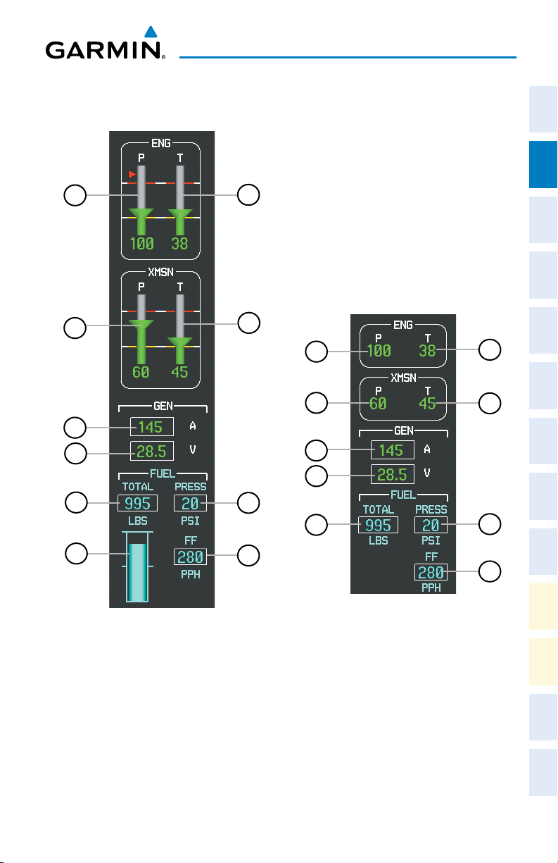
MFD EIS Display (Normal)
190-01254-00 Rev. B
EIS Display (Reversionary)
Garmin G1000H™ Cockpit Reference Guide for the Bell 407GX
Annun/
Alerts Appendix Index
5
Page 22
Engine Indication & Crew Alerting System
Flight
InstrumentsEICAS
Nav/Com/
XPDR/AudioAFCSGPS Nav
Flight
PlanningProcedures
Hazard
Avoidance
Features
Additional
Abnormal
Operation
AlertsAppendixIndex
Annun/
1
Engine Oil Pressure
(P)
2
Oil Temperature
Indicator (T)
3
Transmission Oil
Pressure (P)
4
Transmission Oil
Temperature (T)
5
Ammeter (A)
6
Voltmeter (V)
7
Fuel Quantity
(TOTAL LBS or
FWD LBS)
8
Fuel Pressure
Indicator (PRESS
PSI)
9
Total Fuel Quantity
Gauge
10
Fuel Flow Indicator
(FF PPH)
Displays pressure of oil supplied to the engine
in pounds per square inch (psi). A red
triangle represents the oil pressure limitation
during a cold start (shown in normal mode
only)
Displays engine oil temperature in degrees
Celsius
Displays pressure of oil supplied to the
transmission in pounds per square inch
(psi).
Displays the transmission oil temperature in
degrees Celsius
Displays the DC load in amperes to the nearest
5 amps
Displays the electrical bus voltage
Displays the usable fuel quantity in pounds. By
default, total usable fuel quantity is shown;
when forward fuel tank is selected, ‘FWD’ is
displayed above readout to indicate forward
tank usable fuel quantity is shown.
Displays fuel pressure in pounds per square
inch (psi)
Displays total usable fuel quantity as a bar
graph.
Displays fuel flow in pounds per hour (PPH)
6
Garmin G1000H™ Cockpit Reference Guide for the Bell 407GX
190-01254-00 Rev. B
Page 23
Engine Indication & Crew Alerting System
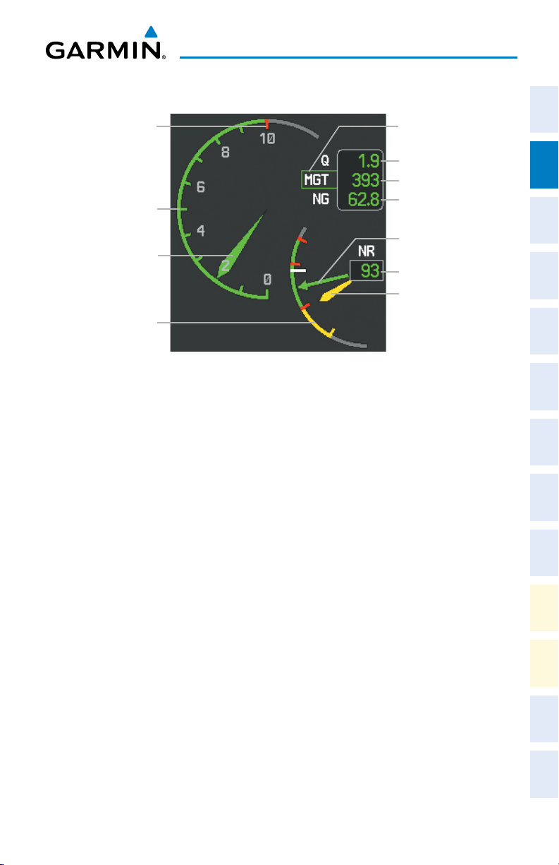
ENGINE POWER AND SPEED INDICATIONS
Maximum Continuous
Power Operation Limit
Box Indicates Parameter
Controlling PSI Indicator
Instruments EICAS
Flight
Torque Readout
MGT Readout
Power Available Gauge
NG Readout
XPDR/Audio AFCS GPS Nav
Nav/Com/
NR Indicator
Power Available
Indicator
NR Readout
NP Indicator
Dual Tachometer Gauge
Power Situation Indicator Gauge and Dual Tachometer Gauge
Planning Procedures
Flight
Power Situation Indicator
The PSI provides the pilot with the amount of power available based on engine
torque (Q; shown as a percentage), measured gas temperature (MGT, degrees Celsius,
°C), and gas producer rotation speeds (NG; shown as a percentage) with respect to
Avoidance
Hazard
operating limitations. In normal conditions, a green box is shown around the label for
the readout currently closest to its maximum continuous power (MCP) limits. This
value also controls a green pointer along a numeric scale from 0 (no power) to 10
Additional
Features
(MCP, shown with a red tick mark).
Operating limits are displayed along the PSI gauge and are calculated dynamically
Operation
in response to all parameters, to show the range of needle movement available beyond
Abnormal
MCP before any parameter reaches the operating limit. Green arcs indicate continuous
operation ranges; yellow arcs indicate transient operating limits. A gray arc becomes
red if the Power Available Indicator enters this range; it indicates an exceedance is
Alerts Appendix Index
Annun/
occurring.
During engine start, a red triangle appears on the PSI arc when MGT is shown to
correspond with MGT starting limits, and remains displayed until the starter has been
disengaged for 5 seconds.
Takeoff Timer
After the engine has been started, if Q or MGT are within the takeoff limitation
ranges, the G1000H displays a 5-minute countdown timer inside the PSI gauge. The
190-01254-00 Rev. B
Garmin G1000H™ Cockpit Reference Guide for the Bell 407GX
7
Page 24
Engine Indication & Crew Alerting System
timer flashes beginning when 30 seconds remain until an exceedance will occur; the
timer is automatically removed when either Q or MGT fall below takeoff limits.
Flight
InstrumentsEICAS
Dual Tachometer
The dual tachometer displays rotor speed (NR) and power turbine speed (NP) as
a percentage of maximum rotation. A readout for NR is provided. The long pointer
represents NR along the gauge scale; NP is shown with the short pointer. A white tick
mark represents the FADEC normal governing point. When Quiet Mode is active, a
Nav/Com/
XPDR/AudioAFCSGPS Nav
magenta reference bug is shown on the tachometer to indicate the Quiet Mode governing
point.
POWER ASSURANCE CHECK
NOTE: Follow the procedures in the Rotorcraft Flight Manual (RFM) for
configuring the helicopter for the power assurance check prior to activating
the feature on the G1000H.
Flight
PlanningProcedures
1)
If the Particle Separator or Snow Baffle are installed, proceed to step 2.
If neither are installed, proceed to step 7.
2)
Turn the large FMS Knob to select the AUX Page group.
3)
Turn the small FMS Knob to select System Setup. If necessary, press the
Hazard
Avoidance
SETUP 1 Softkey to display the System Setup 1 Page
4)
Press the FMS Knob momentarily to activate the flashing cursor.
5)
Turn the large FMS Knob to highlight the desired option field in the Inlet Box.
Features
6)
Additional
Turn the small FMS Knob one click to the right to select ON or one click to
the left to select OFF.
7)
Abnormal
Operation
AlertsAppendixIndex
Annun/
containing a progress meter. If the helicopter configuration for the power assurance
Press the ENGINE Softkey to display the Engine Page.
8)
Press the PWR CHK Softkey.
When the power assurance check is activated a ‘PWR CHECK’ box is displayed
check is invalid, the error message ‘CHK LIMITS’ is displayed. Otherwise, the power
assurance check will complete after ten seconds.
Values that equal or exceed performance minimums will be displayed in white; values
that do not meet performance minimums will be shown with yellow highlighted black
readouts. Dashes are displayed if data used to perform the power assurance check is not
available.
8
Garmin G1000H™ Cockpit Reference Guide for the Bell 407GX
190-01254-00 Rev. B
Page 25
Engine Indication & Crew Alerting System
CREW ALERTING SYSTEM (CAS)
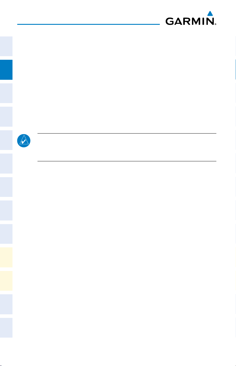
When Crew Alerting System (CAS) messages are generated, a CAS window
containing messages appears to the right of the vertical speed indicator on the PFD.
Pressing the CAS Softkey displays softkeys for scrolling up and down through the
messages in the PFD CAS Window.
PFD CAS
Window
CAS
Scrolling
Softkey (Enabled
when more than
12 messages are
displayed)
CAS Display (PFD)
Instruments EICAS
Flight
XPDR/Audio AFCS GPS Nav
Nav/Com/
Planning Procedures
Flight
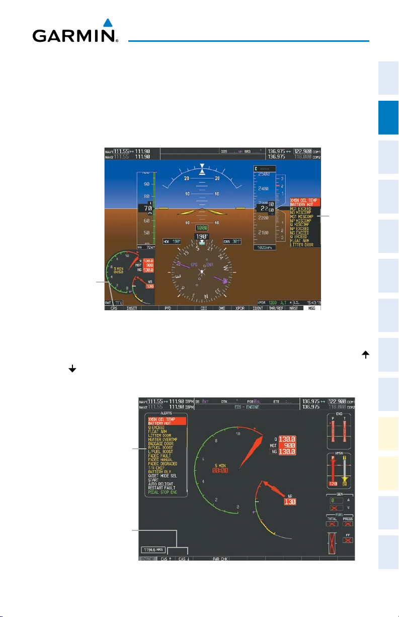
CAS alerts are additionally displayed on the upper left of the EIS - Engine page. Up
Avoidance
to 19 messages can be shown; when more than 19 messages accumulate, the CAS
and CAS Softkeys will become available as needed to permit scrolling up and down
through the messages on this page.
MFD Alerts
window containing
CAS messages
CAS
(Enabled when more than 19
190-01254-00 Rev. B
Scrolling Softkeys
messages are displayed)
Garmin G1000H™ Cockpit Reference Guide for the Bell 407GX
Engine Page CAS Display (MFD)
Features
Operation
Alerts Appendix Index
9
Hazard
Additional
Abnormal
Annun/
Page 26

Engine Indication & Crew Alerting System
CAS MESSAGE PRIORITIZATION
Flight
InstrumentsEICAS
NOTE: Information on CAS messages in this pilot’s guide is always superseded
by the RFM. Refer to the RFM for recommended pilot actions.
CAS messages are grouped by criticality (warning, caution, advisory, safe operating
advisory) and sorted by order of appearance (most recent messages on top). The
color of the message is based on its urgency and on required action. Refer to the
Nav/Com/
XPDR/AudioAFCSGPS Nav
Annunciations and Alerts section for a detailed listing of CAS alerts and alerting
behavior.
• Warning (red) – Immediate crew awareness and immediate crew action
required; accompanied by one or more aural tones; and a and a steady
“WARN” PBA light is illuminated above the PFD.
• Caution (yellow) – Immediate crew awareness and subsequent corrective
action required; accompanied by a and a steady “CAUT” PBA light is
Flight
PlanningProcedures
illuminated above the PFD.
• Advisory (white) – Crew awareness required and subsequent action may be
required.
• Safe Operating Advisory (green) – Crew awareness required.
A CAS message does not appear more than once at a given time. Warning and
caution CAS messages flash when they are generated, and continue to flash until
Hazard
Avoidance
acknowledged, or until the triggered condition is inactive for more than 3 seconds.
Advisory CAS messages are displayed steady until the triggered condition is inactive
for more than 3 seconds.
Features
Additional
After the acknowledgment, a message remains displayed at the top of its respective
priority group in the CAS Window until either a newer message of the same priority
appears or the condition(s) that caused the alert to display no longer exist.
Abnormal
Operation
AlertsAppendixIndex
Annun/
10
Garmin G1000H™ Cockpit Reference Guide for the Bell 407GX
190-01254-00 Rev. B
Page 27

NAV/COM/TRANSPONDER/AUDIO PANEL
ADF TUNING (OPTIONAL)
Tune the ADF using the remote ADF control head.
DME TUNING (OPTIONAL)
1)
Press the DME Softkey.
2)
Turn the large FMS to select the DME source field.
3)
Turn the small FMS Knob to select the desired Nav radio.
4)
Press the ENT Key to complete the selection.
Nav/Com/XPDR/Audio Panel
Instruments EICAS
Flight
XPDR/Audio AFCS GPS Nav
Nav/Com/
ENTER A TRANSPONDER CODE
Planning Procedures
Flight
1)
Press the XPDR Softkey to display the transponder mode selection softkeys.
2)
Press the CODE Softkey to display the transponder code selection softkeys,
for digit entry.
3)
Press the digit softkeys to enter the code in the code field. When entering
the code, the next key in sequence must be pressed within 10 seconds, or
the entry is cancelled and restored to the previous code. Five seconds after
Avoidance
Hazard
the fourth digit has been entered, the transponder code becomes active.
Additional
Features
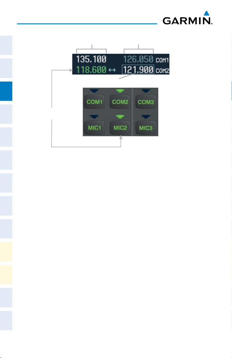
SELECTING A COM RADIO
The COM transceiver is selected for transmitting by pressing the MIC Keys on the
Audio Panel. During reception of audio from the COM radio selected for transmission,
Operation
Abnormal
audio from the other COM radio is muted.
An active COM frequency displayed in green indicates that the COM transceiver is
Annun/
selected on the Audio Panel (MIC1 or MIC2 Key).
Alerts Appendix Index
Frequencies in the standby field are displayed in either white or gray. The standby
frequency in the tuning box is white. The other standby frequency is gray.
190-01254-00 Rev. B
Garmin G1000H™ Cockpit Reference Guide for the Bell 407GX
11
Page 28
Nav/Com/XPDR/Audio Panel
Flight
Active
Fields
InstrumentsEICAS
Standby
Fields
Tuning Box
Nav/Com/
XPDR/AudioAFCSGPS Nav
COM2 Radio is Selected on the
Audio Panel
Flight
PlanningProcedures
Selecting a COM Radio for Transmit
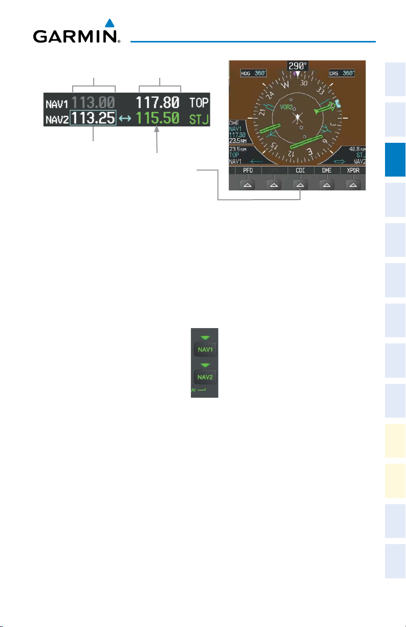
SELECTING A NAV RADIO
A NAV radio is selected for navigation by pressing the CDI Softkey located on the
PFD. The active NAV frequency selected for navigation is displayed in green. Pressing
the CDI Softkey once selects NAV1 as the navigation radio. Pressing the CDI Softkey
Hazard
Avoidance
a second time selects NAV2 as the navigation radio. Pressing the CDI Softkey a third
time activates GPS mode. Pressing the CDI Softkey again cycles back to NAV1.
While cycling through the CDI Softkey selections, the NAV Tuning Box and the
Features
Additional
Frequency Transfer Arrow are placed in the active NAV Frequency Field and the active
NAV frequency color changes to green.
Abnormal
The three navigation modes that can be cycled through are:
Operation
• VOR1(orLOC1)–IfNAV1isselected,agreen single line arrow (not shown)
AlertsAppendixIndex
Annun/
labeled either VOR1 or LOC1 is displayed on the HSI and the active NAV1
frequency is displayed in green.
• VOR2(orLOC2)–IfNAV2isselected,agreen double line arrow (shown) labeled
either VOR2 or LOC2 is displayed on the HSI and the active NAV2 frequency
is displayed in green.
• GPS–IfGPSModeisselected,amagenta single line arrow (not shown) appears
on the HSI and neither NAV radio is selected. Both active NAV frequencies are
then displayed in white.
12
Garmin G1000H™ Cockpit Reference Guide for the Bell 407GX
190-01254-00 Rev. B
Page 29
Nav/Com/XPDR/Audio Panel
Standby
Fields
Tuning Box
Active
Fields
Instruments EICAS
Flight
XPDR/Audio AFCS GPS Nav
Nav/Com/
The NAV Radio is Selected
by Pressing the
CDI
Softkey
Selecting a NAV Radio for Navigation
See the Flight Instruments Section for selecting the DME (optional) and Bearing
Information windows and using VOR as the source for the bearing pointer.
NAV radios are selected for listening by pressing the corresponding keys on the
Planning Procedures
Flight
Audio Panel. Pressing the NAV1,or NAV2 Key selects and deselects the navigation
radio source. Selected audio can be heard over the headset and the speaker (if selected).
All radios can be selected individually or simultaneously.
Avoidance
Hazard
NAV/COM TUNING
1)
Press the small tuning knob to select the desired radio for tuning. A light
blue box highlights the radio frequency to be tuned.
2)
Turn the respective tuning knobs to enter the desired frequency into the
standby frequency field. The large knob enters MHz and the small knob
enters kHz.
3)
Press the Frequency Transfer Key to place the frequency into the active
frequency field.
190-01254-00 Rev. B
Selecting a NAV Radio Receiver
Garmin G1000H™ Cockpit Reference Guide for the Bell 407GX
13
Additional
Features
Operation
Abnormal
Annun/
Alerts Appendix Index
Page 30
Nav/Com/XPDR/Audio Panel
DIGITAL CLEARANCE RECORDER AND PLAYER (OPTIONAL)
Flight
The Audio Panel contains a digital clearance recorder that records up to 2.5 minutes
InstrumentsEICAS
of the selected COM radio signal. Recorded COM audio is stored in separate memory
blocks. Once 2.5 minutes of recording time have been reached, the recorder begins
recording over the stored memory blocks, starting from the oldest block.
An optional external Play button controls the play function. Pressing the Play
button once plays the latest recorded memory block.
Nav/Com/
Pressing the MKR/MUTE Key during play of a memory block stops play. If a COM
XPDR/AudioAFCSGPS Nav
input signal is detected during play of a recorded memory block, play is halted.
Pressing the optional Play button while audio is playing begins playing the
previously recorded memory block. Each subsequent press of the Play button selects
the previously recorded memory block.
Powering off the unit automatically clears all recorded blocks.
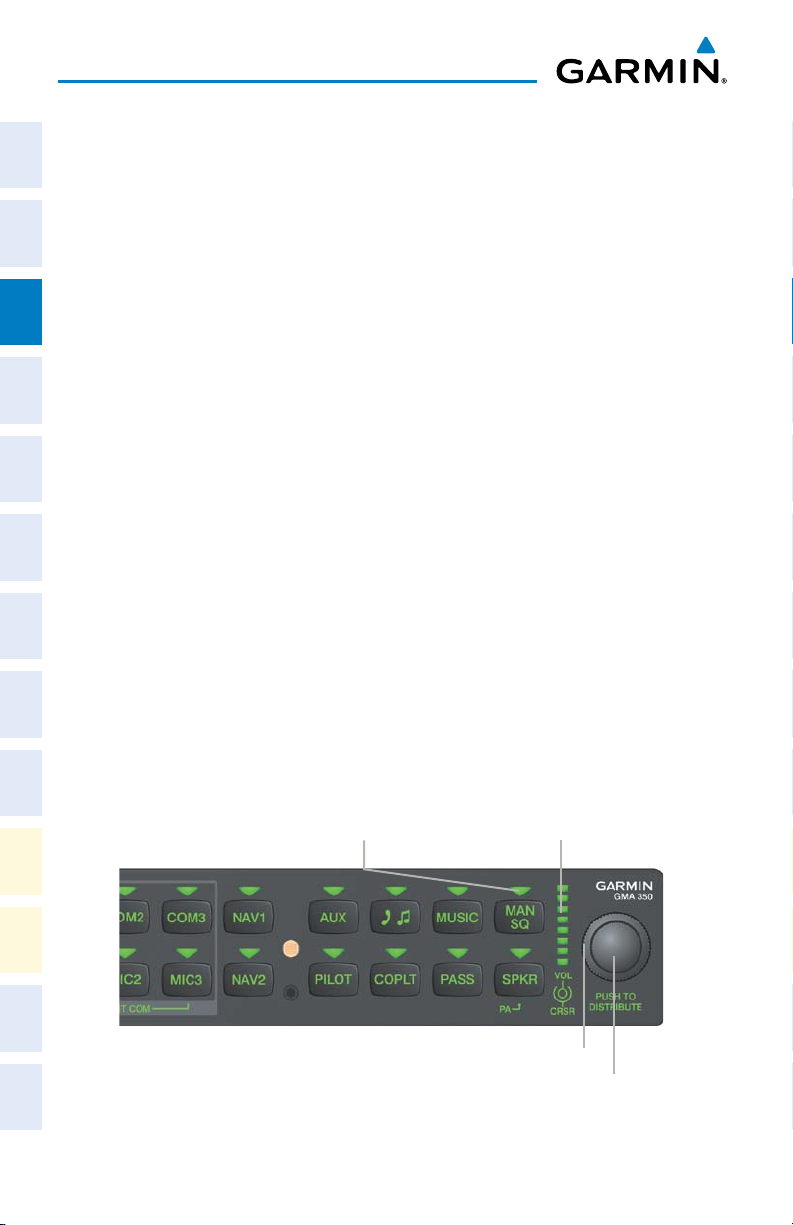
INTERCOM VOLUME AND SQUELCH
Flight
PlanningProcedures
The VOL/CRSR Knob controls selection and volume or manual intercom squelch
adjustment for audio sources that may not be adjustable anywhere else in the system.
The small knob controls the volume or squelch. Turning the large knob activates and/
or moves the cursor (flashing green annunciator or flashing blue annunciator in BlueSelect Mode) to select the audio source to adjust. The cursor will time-out after a few
seconds and the position of the cursor will always default back to the PILOT Key.
Hazard
Avoidance
Pressing the small knob cancels the cursor.
Features
Additional
Abnormal
Operation
AlertsAppendixIndex
Annun/
14
Manual Squelch Annunciator; Off for
Automatic Squelch, On for Manual
Squelch
Relative Volume/
Squelch Scale
Volume or Manual Squelch
Volume/Squelch Control
Garmin G1000H™ Cockpit Reference Guide for the Bell 407GX
Cursor
190-01254-00 Rev. B
Page 31

Nav/Com/XPDR/Audio Panel
INTERCOM MODES
NOTE:
When in Split-COM mode, the copilot will only hear alerts and the
Instruments EICAS
higher numbered of the two selected COMs (COM2 or COM3).
All Intercom Mode
In ‘All Intercom’ mode the Pilot, Copilot, and Passengers hear each other and hear
the aircraft audio.
Aircraft Audio
PILOT COPLT
XPDR/Audio AFCS GPS Nav
Planning Procedures
PASS
Avoidance
Flight
Nav/Com/
Flight
Hazard
190-01254-00 Rev. B
ICS Keys Mode Operation
Garmin G1000H™ Cockpit Reference Guide for the Bell 407GX
15
Additional
Features
Operation
Abnormal
Annun/
Alerts Appendix Index
Page 32

Nav/Com/XPDR/Audio Panel
Pilot Isolate Mode
Flight
Nav/Com/
Flight
In ‘Pilot Isolate’ mode the Pilot, Copilot, and Passengers hear the aircraft audio.
InstrumentsEICAS
The Copilot and Passengers also hear each other.
XPDR/AudioAFCSGPS Nav
PlanningProcedures
ICS Keys Mode Operation
Passenger/Crew Isolate Mode
In ‘Passenger/Crew Isolate’ mode the Pilot and Copilot hear the aircraft audio and
each other. The Passengers hear each other.
Hazard
Avoidance
Aircraft Audio
PILOT
Aircraft Audio
COPLT
PASS
Features
Additional
Abnormal
Operation
AlertsAppendixIndex
Annun/
16
COPLTPILOT
ICS Keys Mode Operation
Garmin G1000H™ Cockpit Reference Guide for the Bell 407GX
PASS
190-01254-00 Rev. B
Page 33
Nav/Com/XPDR/Audio Panel
Copilot Isolate Mode
Instruments EICAS
Flight
In ‘Copilot Isolate’ mode the Pilot, Copilot, and Passengers hear the aircraft audio.
The Pilot and Passengers also hear each other. The Copilot has the option to use SplitCOM mode.
Aircraft Audio
XPDR/Audio AFCS GPS Nav
Nav/Com/
PILOT
PASS
COPLT
Planning Procedures
Flight
ICS Keys Mode Operation
All Isolate Mode
Avoidance
Hazard
In ‘All Isolate’ mode the Pilot and Copilot hear the aircraft audio. The Copilot has
the option to use Split-COM mode. The Passengers hear each other.
Additional
Aircraft Audio
Features
190-01254-00 Rev. B
ICS Keys
COPLTPILOT
Mode Operation
Garmin G1000H™ Cockpit Reference Guide for the Bell 407GX
PASS
17
Operation
Abnormal
Annun/
Alerts Appendix Index
Page 34

Nav/Com/XPDR/Audio Panel
Pilot & Copilot Isolate Mode
Flight
In ‘Pilot & Copilot Isolate’ mode the Pilot, Copilot, and Passengers hear the aircraft
InstrumentsEICAS
audio. The Passengers hear each other. The Copilot has the option to use Split-COM
mode.
Aircraft Audio
Nav/Com/
XPDR/AudioAFCSGPS Nav
PILOT COPLT
PASS
ICS Keys Mode Operation
Pilot & Passenger Isolate Mode
In ‘Pilot & Passenger Isolate’ mode the Pilot and Copilot hear the aircraft audio.
The Passengers hear each other.
Flight
Hazard
PlanningProcedures
Avoidance
Aircraft Audio
PILOT PASS
COPLT
ICS Keys Mode Operation
Features
Additional
Copilot & Passenger Isolate Mode
In ‘Copilot & Passenger Isolate’ mode the Pilot and Copilot can hear the aircraft
Abnormal
Operation
audio. The Copilot has the option to use Split-COM mode. The Passengers hear each
other.
AlertsAppendixIndex
Annun/
18
ICS Keys Mode Operation
Garmin G1000H™ Cockpit Reference Guide for the Bell 407GX
Aircraft Audio
PILOT
COPLT
PASS
190-01254-00 Rev. B
Page 35

Nav/Com/XPDR/Audio Panel
Blue-Select Mode (Telephone/Entertainment Distribution)
Instruments EICAS
Flight
The music (MUSIC) and telephone/entertainment ( ) audio are distributed
using the Blue-Select Mode. The following example indicates that the pilot, copilot,
and passengers will all hear the telephone/entertainment audio.
XPDR/Audio AFCS GPS Nav
Nav/Com/
Blue-Select Mode (Telephone/Entertainment Distribution)
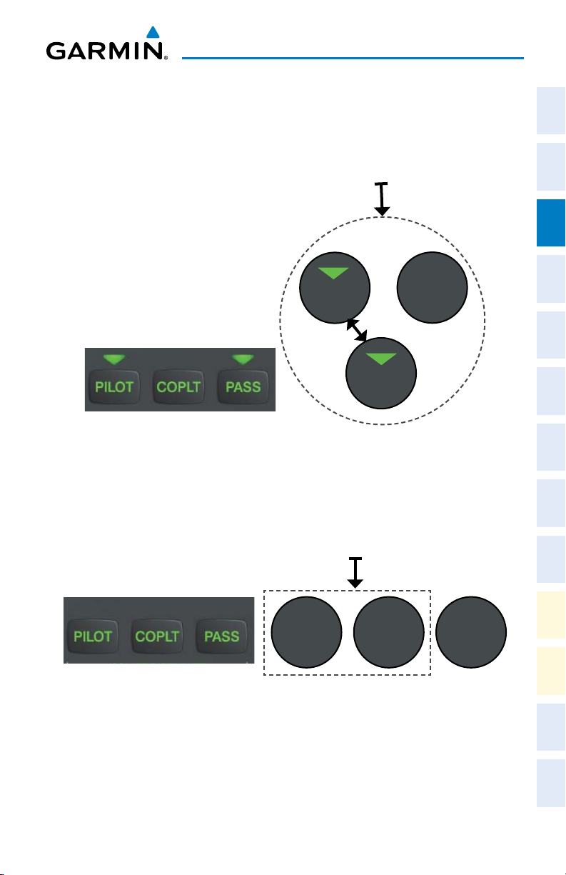
The Blue-Select Mode is entered by pressing the small knob when the the volume
Planning Procedures
Flight
control cursor (flashing green annunciator) is not active. If the voume control cursor
is active, press the small knob twice. The first press will cancel the volume control
cursor, the second will activate Blue-Select Mode.
The annunciator over the Button will be flashing blue. Any combination of
the annunciators over the PILOT, COPLT, and PASS buttons may be blue. Select the
desired button to turn the blue annunciator on or off to distribute the telephone audio
Avoidance
Hazard
to selected crew/passenger positions. Turn the large knob to select MUSIC, and select
the crew/passenger positions to receive the music audio.
Additional
Features
Selecting any button other than PILOT, COPLT, PASS , MUSIC or will
cancel Blue-Select Mode. Pressing the small knob will also cancel Blue-Select Mode.
After approximately ten seconds with no input, the Blue-Select Mode will automatically
Operation
Abnormal
cancel.
Annun/
PASSENGER ADDRESS MODE (PA MODE)
Alerts Appendix Index
Press and hold the SPKR Key for 2 seconds to initiate Passenger Address Mode. PA
Mode is annunciated by a rapid blinking of the SPKR annunciator. When in PA Mode
the crew can use the PTT “Push-to-Talk” button to deliver announcements over the
speaker, to the passenger headsets, or both depending on configuration.
190-01254-00 Rev. B
Garmin G1000H™ Cockpit Reference Guide for the Bell 407GX
19
Page 36

Nav/Com/XPDR/Audio Panel
SPLIT-PA MODE
Flight
During Split-PA Mode the pilot can continue to use the radio(s) while the copilot
InstrumentsEICAS
delivers PA announcements. To initiate Split-PA Mode, first enter Split-COM Mode by
pressing more that one MIC Keys simultaneously, then press and hold the SPKR Key
for 2 seconds.
3D AUDIO
Nav/Com/
XPDR/AudioAFCSGPS Nav
3D Audio is useful when multiple audio sources are present. By using different
responses in each ear, 3D audio processing creates the illusion that each audio source
is coming from a unique location or seat position.
Because this feature uses different signals for left and right channels, it requires
wiring for stereo intercom and stereo headsets. If 3D audio is activated when mono
headsets are in use, the listener will still hear all audio sources; however, there is no
benefit from location separation.
With a single COM selected and 3D Audio enabled, the listener hears the audio
Flight
PlanningProcedures
source at the 12 o’clock position. If all three COMs are selected, the listener hears
the audio sources at the 11, 12 and 1 o’clock positions with the COM numbers
increasing clockwise. If two COMs are selected, the listener hears COM1 at the 11
o’clock position and COM2 at the 1 o’clock position. All other intercom positions
are processed to sound like their relative seat location. By default, the GMA 350H
assumes the pilot sits in the right seat. A Garmin authorized service center can make
Hazard
Avoidance
changes to the default configuration.
ENABLING 3D AUDIO
Features
Additional
Press and hold the PILOT Key to toggle 3D audio processing on and off for all
headset positions. When 3D Audio is enabled, the aural message “3D audio left” is
heard in the left ear followed by “3D audio right” in the right ear.
Abnormal
Operation
3D AUDIO TROUBLESHOOTING
AlertsAppendixIndex
Annun/
If the aural messages are not heard in only the left and then the right ear respectively
the cause may be aircraft wiring or headset settings. Refer to the following table if a
headset or aircraft wiring problem is suspected.
20
Garmin G1000H™ Cockpit Reference Guide for the Bell 407GX
190-01254-00 Rev. B
Page 37

Nav/Com/XPDR/Audio Panel
3D Audio Troubleshooting
Symptom(s) Cause(s) Solution(s)
“3D audio left”
message heard
in both ears.
“3D audio right”
message not
heard
“3D audio left”
message heard
in both ears,
followed by “3D
audio right”
message heard
in both ears
“3D audio right”
message heard
in both ears.
“3D audio left”
not heard
“3D audio left”
message heard
in right ear only
followed by “3D
audio right”
message heard
in left ear only
1) Mono headset in use 1) Use a stereo headset
2) Stereo headset in use
with mono/stereo switch
2) Set mono/stereo switch on headset
to ‘stereo’
set to ‘mono’
3) Aircraft wiring has left
audio wired to both left
and right channels of
stereo headset jack
3) If after checking solutions #1 and
#2 see a service center as soon as
possible to inspect/correct wiring.
This wiring fault can cause fail-safe
audio not to function.
1) Mono headset in use 1) Use a stereo headset
2) Stereo headset in use
with mono/stereo switch
2) Set mono/stereo switch on headset
to ‘stereo’
set to mono
3) Incorrect aircraft wiring
(left/right shorted
together)
3) If after checking solutions #1 and
#2 see a service center as soon as
possible to inspect/correct wiring.
This wiring fault can cause fail-safe
audio not to function.
1) Incorrect aircraft wiring
(right channel used for
mono instead of left or
left/right swapped)
1) Stereo headset is on
backwards
1) See a service center as soon as
possible to inspect/correct wiring.
This wiring fault can cause fail-safe
audio not to function.
1) Verify correct orientation from the
left/right indication on each side of
the headset or the position of the
boom mic (usually attached on left
side). If the headset is backwards
left/right position information will be
swapped.
2) Incorrect aircraft wiring
(left/right channels
swapped)
2) See a service center as soon as
possible to inspect/correct wiring.
This wiring fault can cause fail-safe
audio not to function.
Instruments EICAS
Flight
XPDR/Audio AFCS GPS Nav
Nav/Com/
Planning Procedures
Flight
Avoidance
Hazard
Additional
Features
Operation
Abnormal
Annun/
Alerts Appendix Index
190-01254-00 Rev. B
Garmin G1000H™ Cockpit Reference Guide for the Bell 407GX
21
Page 38

Nav/Com/XPDR/Audio Panel
Flight
Nav/Com/
Symptom(s) Cause(s) Solution(s)
InstrumentsEICAS
“3D audio left”
message heard
1) Aircraft wired for mono
intercom
in left ear only,
no audio heard
in right ear.
“3D audio right”
XPDR/AudioAFCSGPS Nav
message heard
in right ear only,
no audio heard
1) Incorrect aircraft wiring
(right channel used for
mono instead of left, or
left/right swapped)
in left ear
VOICE RECOGNITION
3D Audio Troubleshooting
1) See a service center to wire the
installation for stereo headsets.
1) See a service center as soon as
possible to inspect/correct wiring.
This wiring fault can cause fail-safe
audio not to function.
3D Audio Troubleshooting
Flight
Voice Recognition allows the pilot (and optionally copilot) to control the GMA
PlanningProcedures
350H using spoken commands. To activate Voice Recognition, push and hold the
Push-To-Command (PTC) button while speaking a command. When the Push-ToCommand button is released, the GMA 350H will respond.
If a command is correctly interpreted by the GMA 350H, a positive acknowlege-
ment chime will be played, and the pilot should verify that the correct button selection
Hazard
is indicated by the triangular annunciator lights. Alternatively, some commands will
Avoidance
be indicated by a voice response from the GMA 350H. If the desired modes are not
indicated by annunciator lights or a voice response, the pilot should repeat the com-
Features
mand by using the Push-To-Command button, or by manually using the front panel
Additional
controls of the GMA 350H.
If a command is incorrectly interpreted by the GMA 350H, a negative acknowlege-
Abnormal
Operation
ment tone will be played. The pilot should repeat the command by using the PushTo-Command button, or by manually using the front panel controls of the GMA 350H.
In the event of any abnormal Voice Recognition operation, at any time the front panel
AlertsAppendixIndex
Annun/
controls may be used manually to control the GMA 350H.
The following table lists the available Voice Recognition commands, the associated
actions, and the voice response if applicable:
22
Garmin G1000H™ Cockpit Reference Guide for the Bell 407GX
190-01254-00 Rev. B
Page 39

Nav/Com/XPDR/Audio Panel
Control Spoken Command Action Confirmation of Action
“COM one”
Toggles
COM1
Illuminate/Extinguish COM1
Annunciator
“MIC one”
Selects MIC1 Illuminate MIC1 Annunciator
“COM one MIC”
“COM two”
Toggles
COM2
Illuminate/Extinguish COM2
Annunciator
“MIC two”
Selects MIC2 Illuminate MIC2 Annunciator
“COM two MIC”
“COM three”
Toggles
COM3
Illuminate/Extinguish COM3
Annunciator
“MIC three”
Selects MIC3 Illuminate MIC3 Annunciator
“COM three MIC”
COM
“Split COM”
“Split COM 1 2”
“Split COM 1 3”
“Split COM 2 3”
Selects split
COM 1/2
Selects split
COM 1/2
Selects split
COM 1/3
Selects split
COM 2/3
Illuminate MIC1/MIC2
Annunciators
Illuminate MIC1/MIC2
Annunciators
Illuminate MIC1/MIC3
Annunciators
Illuminate MIC2/MIC3
Annunciators
Mutes
monitored
“Monitored COM mute” or
“Mute monitored COM”
COM on
primary
Voice Response:
“Monitor mute enabled”
COM
reception
“Disable monitored COM mute”
or
“Monitored COM mute disable”
or
“Disable mute monitored COM”
or
“Mute monitored COM disable”
Disables
monitored
COM mute
on primary
COM
reception
Voice Response:
“Monitor mute disabled”
Instruments EICAS
Flight
XPDR/Audio AFCS GPS Nav
Nav/Com/
Planning Procedures
Flight
Avoidance
Hazard
Additional
Features
Operation
Abnormal
Annun/
Alerts Appendix Index
190-01254-00 Rev. B
Garmin G1000H™ Cockpit Reference Guide for the Bell 407GX
23
Page 40

Nav/Com/XPDR/Audio Panel
Control Spoken Command Action Confirmation of Action
Flight
InstrumentsEICAS
Nav/Com/
XPDR/AudioAFCSGPS Nav
Flight
PlanningProcedures
Hazard
Avoidance
Features
Additional
Abnormal
Operation
AlertsAppendixIndex
Annun/
NAV
AUX
MUSIC
Speaker
(SPKR)
PA “P - A”
“NAV one”
“NAV two”
“Auxiliary”
“Telephone” or
“Phone” or
“Telephone mute” or
“Phone mute” or
“Jack mute”or
“Mute telephone” or
“Mute phone” or
“Mute jack”
“Disable telephone mute” or
“Disable phone mute” or
“Disable jack mute”or
“Telephone mute disable”or
“Phone mute disable” or
“Jack mute disable”
“MUSIC mute” or
“Mute MUSIC”
“Disable MUSIC mute” or
“MUSIC mute disable”
“Speaker”
“AUX” or
“Jack”
“MUSIC”
Toggles
NAV1
Toggles
NAV2
Toggles AUX
Toggles
Telephone/
Jack
Mutes
Telephone/
Jack on radio
reception
Disables
Telephone/
Jack mute
on radio
reception
Toggles
MUSIC
Mutes
MUSIC
on radio
reception
Disables
MUSIC mute
on radio
reception
Toggles
SPKR on/off
Toggles PA
on/off
Illuminate/Extinguish NAV1
Annunciator
Illuminate/Extinguish NAV2
Annunciator
Illuminate/Extinguish AUX
Annunciator
Illuminate/Extinguish
Annunciator
Voice Response:
“Tel and jack mute enabled”
Voice Response:
“Tel and jack mute disabled”
Illuminate/Extinguish MUSIC
Annunciator
Voice Response:
“Music mute enabled”
Voice Response:
“Music mute disabled”
Illuminate/Extinguish SPKR
Annunciator
SPKR Annunciator blinks in
PA mode
24
Garmin G1000H™ Cockpit Reference Guide for the Bell 407GX
190-01254-00 Rev. B
Page 41

Nav/Com/XPDR/Audio Panel
Control Spoken Command Action Confirmation of Action
ICS Isolation
“Pilot”
“Copilot”
“Passenger” or
“Pass”
“Passenger mute” or
“Pass mute” or
“Mute passenger” or
“Mute pass”
Toggles
PILOT button
Toggles
COPLT
button
Toggles
PASS button
Mutes
passengers
during radio
reception
Illuminate/Extinguish PILOT
Annunciator
Illuminate/Extinguish COPLT
Annunciator
Illuminate/Extinguish PASS
Annunciator
Voice Response:
“Passenger mute enabled”
“Disable passenger mute” or
“Disable pass mute” or
“Disable mute passenger” or
“Disable mute pass” or
“Passenger mute disable” or
“Pass mute disable” or
Disables
muting of
passengers
during radio
reception
Voice Response:
“Passenger mute disabled”
“Mute passenger disable” or
“Mute pass disable”
Configures
Copilot as a
passenger
Configures
Copilot as
flight crew
Voice Response:
“Copilot is passenger”
Voice Response:
“Copilot is crew”
Copilot
Configuration
“Copilot is passenger” or
“Copilot is pass”
“Copilot is crew”
Marker
Beacon
Marker
Beacon (MKR/
MUTE)
“Marker” or
“Mute marker” or
“Marker mute”
audio on/
off (refer
to Marker
Beacon
Illuminate/Extinguish MKR/
MUTE Annunciator
section for
details)
Cancels
cursor when
cursor is
flashing
Cursor is removed
Cursor
“Cursor off” or
“Cursor cancel” or
“Cancel cursor”
Instruments EICAS
Flight
XPDR/Audio AFCS GPS Nav
Nav/Com/
Planning Procedures
Flight
Avoidance
Hazard
Additional
Features
Operation
Abnormal
Annun/
Alerts Appendix Index
190-01254-00 Rev. B
Garmin G1000H™ Cockpit Reference Guide for the Bell 407GX
25
Page 42

Nav/Com/XPDR/Audio Panel
Control Spoken Command Action Confirmation of Action
Flight
InstrumentsEICAS
Nav/Com/
XPDR/AudioAFCSGPS Nav
Flight
PlanningProcedures
Hazard
Avoidance
Features
Additional
Abnormal
Operation
AlertsAppendixIndex
Annun/
Manual
Squelch
COM
Clearance
Recorder
Distribution
(Blue Mode)
“Manual squelch” or
“Man squelch”
“Manual squelch threshold up”
“Manual squelch volume up” or
“Man squelch threshold up” or
“Man squelch volume up”
“Manual squelch threshold
“Manual squelch volume down”
“Man squelch threshold down”
“Man squelch volume down”
NOTE: Finer manual squelch adjustment may be made using the dual
concentric knobs on the GMA 350H. The voice command “Up” or “Down” is
equivalent to three clicks of the inner knob..
“Read back” or
“Say again”
“Distribute telephone to
(**desired position(s))” or
“Distribute phone to (**desired
position(s))” or
“Distribute jack to (**desired
position(s))”
“Distribute music to (**desired
position(s))”
** Desired position(s) = “All”, “none”, “pilot”, “copilot”, “passenger”, “pass”,
or any combination of pilot, copilot, passenger, or pass.
or
down” or
or
or
“Play” or
Toggles
manual
squelch
Increases
manual
squelch
threshold
Decreases
manual
squelch
threshold
Plays
recorded
clearance
audio (refer
to Clearance
Recorder
section for
details)
Distributes
TEL/JACK
to desired
positions
Distributes
MUSIC to
desired
position(s)
Illuminate/Extinguish MAN
SQ Annunciator
Manual squelch threshold
increased
Manual squelch threshold
decreased
Recorded audio playing
TEL/JACK audio heard at
desired position(s)
MUSIC heard at desired
position(s)
26
Garmin G1000H™ Cockpit Reference Guide for the Bell 407GX
190-01254-00 Rev. B
Page 43

Nav/Com/XPDR/Audio Panel
Control Spoken Command Action Confirmation of Action
Increases
“(*Desired selection) volume up”
volume
of desired
Volume of desired selection
increased
selection
Decreases
Volume
Adjustments
“(*Desired selection) volume
down”
volume
of desired
selection
Volume of desired selection
decreased
NOTE: Finer volume adjustment may be made using the dual concentric knobs
on the GMA 350H. The voice command “Up” or “Down” is equivalent to three
click of the inner knob.
* Desired selection = “speaker”, “pilot”, “copilot”, “passenger”, “pass”,
“marker”, “aux”, “auxiliary”, “telephone”, “phone”, “jack”, or “music”.
Voice Response:
“Three-D audio left, three-D
audio right”
Voice Response:
“Standard Audio”
3D Audio
“Three-D audio”
“Standard audio”
Enables 3D
audio
Enables
standard
audio
(disables 3D
audio)
Voice Recognition Commands
Instruments EICAS
Flight
XPDR/Audio AFCS GPS Nav
Nav/Com/
Planning Procedures
Flight
Avoidance
Hazard
190-01254-00 Rev. B
Garmin G1000H™ Cockpit Reference Guide for the Bell 407GX
27
Additional
Features
Operation
Abnormal
Annun/
Alerts Appendix Index
Page 44

Nav/Com/XPDR/Audio Panel
Flight
InstrumentsEICAS
Nav/Com/
XPDR/AudioAFCSGPS Nav
Flight
PlanningProcedures
Blank Page
Hazard
Avoidance
Features
Additional
Abnormal
Operation
AlertsAppendixIndex
Annun/
28
Garmin G1000H™ Cockpit Reference Guide for the Bell 407GX
190-01254-00 Rev. B
Page 45

AUTOMATIC FLIGHT CONTROL SYSTEM
Not available.
AFCS
Instruments EICAS
Flight
XPDR/Audio AFCS GPS Nav
Nav/Com/
Planning Procedures
Flight
190-01254-00 Rev. B
Garmin G1000H™ Cockpit Reference Guide for the Bell 407GX
29
Avoidance
Hazard
Additional
Features
Operation
Abnormal
Annun/
Alerts Appendix Index
Page 46

Flight
InstrumentsEICAS
Nav/Com/
XPDR/AudioAFCSGPS Nav
Flight
PlanningProcedures
AFCS
Blank Page
Hazard
Avoidance
Features
Additional
Abnormal
Operation
AlertsAppendixIndex
Annun/
30
Garmin G1000H™ Cockpit Reference Guide for the Bell 407GX
190-01254-00 Rev. B
Page 47

GPS NAVIGATION
DIRECT-TO NAVIGATION
Direct-to Navigation from the MFD
1)
Press the Direct-to
2)
Enter the waypoint identifier.
3)
Press the ENT Key to confirm the identifier. The ‘Activate?’ field is
highlighted.
4)
If no altitude constraint or course is desired, press the ENT Key to activate.
To enter an altitude constraint, proceed to step 5.
5)
Turn the large FMS Knob to place the cursor over the ‘VNV’ altitude field.
6)
Enter the desired altitude.
7)
Press the ENT Key. If the waypoint entered is an airport, the option to
select MSL or AGL is now displayed. If the waypoint is not an airport,
proceed to step 9.
8)
Turn the small FMS Knob to select ‘MSL’ or ‘AGL’.
9)
Press the ENT Key. The cursor is now flashing in the VNV offset distance
field.
10)
Enter the desired offset distance before (-) the waypoint.
11)
Press the ENT Key. The ‘Activate?’ field is highlighted.
12)
Press the ENT Key to activate.
( )
Key.
GPS Navigation
Instruments EICAS
Flight
XPDR/Audio AFCS GPS Nav
Nav/Com/
Planning Procedures
Flight
Avoidance
Hazard
Additional
Features
Direct-to Navigation from the PFD
1)
Press the Direct-to Key
2)
Turn the large FMS Knob to place the cursor in the desired selection field.
3)
Turn the small FMS Knob to begin selecting the desired identifier, location,
etc.
4)
Press the ENT Key.
5)
The cursor is now flashing on ‘ACTIVATE?’. If no altitude constraint or
course is desired, press the ENT Key to activate. To enter an altitude
constraint, proceed to step 6.
6)
Turn the large FMS Knob to place the cursor over the ‘ALT’ altitude field.
190-01254-00 Rev. B
Garmin G1000H™ Cockpit Reference Guide for the Bell 407GX
( )
Operation
Abnormal
.
Annun/
Alerts Appendix Index
31
Page 48

GPS Navigation
7)
Turn the small FMS Knob to enter the desired altitude.
8)
Flight
InstrumentsEICAS
Nav/Com/
XPDR/AudioAFCSGPS Nav
ACTIVATE A STORED FLIGHT PLAN
Flight
PlanningProcedures
Hazard
Avoidance
Features
Additional
Press the ENT Key. If the waypoint entered is an airport, the option to
select MSL or AGL is now displayed. If the waypoint is not an airport,
proceed to step 10.
9)
Turn the small FMS Knob to select ‘MSL’ or ‘AGL’.
10)
Press the ENT Key. The cursor is placed in the OFFSET distance field.
11)
Turn the small FMS Knob to enter the desired target altitude offset from
the selected Direct-to.
12)
Press the ENT Key to highlight ‘Activate?’ or turn the large FMS Knob to
highlight the ‘CRS’ field.
13)
Turn the small FMS Knob to enter the desired course to the waypoint.
14)
Press the ENT Key to highlight ‘ACTIVATE?’.
15)
Press the ENT again to activate the Direct-to.
1)
Press the FPL Key on the MFD and turn the small FMS Knob to display the
Flight Plan Catalog Page.
2)
Press the FMS Knob to activate the cursor.
3)
Turn the large FMS Knob to highlight the desired flight plan
4)
Press the ACTIVE Softkey. The confirmation window is now displayed.
5)
With ‘OK’ highlighted, press the ENT Key to activate the flight plan. To cancel
the flight plan activation, turn the large FMS Knob to highlight ‘CANCEL’ and
press the ENT Key.
ACTIVATE A FLIGHT PLAN LEG
Abnormal
Operation
1)
From the Active Flight Plan Page, press the FMS Knob to activate the cursor
AlertsAppendixIndex
Annun/
and turn the large FMS Knob to highlight the desired waypoint.
2)
Press the ACT LEG Softkey on the MFD.
OR
3)
Press the MENU Key, select the ‘Activate Leg’ option from the page menu
and press the ENT Key. This step must be used when activating a leg from
the PFD.
4)
With ‘Activate’ highlighted, press the ENT Key.
32
Garmin G1000H™ Cockpit Reference Guide for the Bell 407GX
190-01254-00 Rev. B
Page 49

GPS Navigation
STOP NAVIGATING A FLIGHT PLAN
1)
Press the FPL Key to display the Active Flight Plan Page.
2)
Press the MENU Key to display the Page Menu Window.
3)
Turn the large FMS Knob to highlight ‘Delete Flight Plan’ and press the ENT
Key. With ‘OK’ highlighted, press the ENT Key to deactivate the flight plan.
This does not delete the stored flight plan, only the active flight plan.
Instruments EICAS
Flight
XPDR/Audio AFCS GPS Nav
Nav/Com/
VERTICAL NAVIGATION (VNAV)
The navigation database only contains altitudes for procedures that call for “Cross
at” altitudes. If the procedure states “Expect to cross at,” the altitude is not in the
database. In this case the altitude may be entered manually.
Planning Procedures
Flight
Large White
Text
Large Light
Blue Text
Avoidance
Small Light
Blue Text
Hazard
190-01254-00 Rev. B
Small Light
Blue Subdued
Small White Text
with Altitude
Restriction Bar
Cross AT or ABOVE 5,000 ft
Cross AT 2,300 ft
Cross AT or BELOW 3,000 ft
Garmin G1000H™ Cockpit Reference Guide for the Bell 407GX
Text
33
Additional
Features
Operation
Abnormal
Annun/
Alerts Appendix Index
Page 50

GPS Navigation
Altitudes associated with approach procedures are “auto-designated”. This means
the system automatically uses the altitudes loaded with the approach for giving vertical
Flight
InstrumentsEICAS
flight path guidance outside the FAF. Note these altitudes are displayed as small light
blue text.
Altitudes associated with arrival procedures are “manually-designated”. This means
the system does not use the altitudes loaded with the arrival for giving vertical flight
path guidance until designated to do so by the pilot. Note that these altitudes are
initially displayed as white text. These altitudes may be “designated” by placing the
Nav/Com/
XPDR/AudioAFCSGPS Nav
cursor over the desired altitude and pressing the ENT Key. After designation, the text
changes to light blue.
Altitudes that have been designated for use in vertical navigation may also be
made “non-designated” by placing the cursor over the desired altitude and pressing
the CLR Key. The altitude is now displayed only as a reference. It will not be used
to give vertical flight path guidance. Other displayed altitudes may change due to
re-calculations or rendered invalid as a result of manually changing an altitude to a
non-designated altitude.
Flight
PlanningProcedures
White Text Light Blue Text Light Blue
Subdued Text
Hazard
Avoidance
Features
Additional
Abnormal
Operation
AlertsAppendixIndex
Annun/
Large Text
Small Text
34
Altitude calculated by the
system estimating the
altitude of the aircraft as it
passes over the navigation
point. This altitude is
provided as a reference
and is not designated to
be used in determining
vertical flight path
Altitude has been entered
by the pilot. Altitude is
designated for use in
giving vertical flight path
guidance. Altitude does
not match the published
altitude in navigation
database or no published
altitude exists.
guidance.
Altitude is not designated
to be used in determining
vertical flight path
guidance. Altitude has
been retrieved from the
navigation database and
is provided as a reference.
Altitude is designated for
use in giving vertical flight
path guidance. Altitude
has been retrieved from
the navigation database
or has been entered by
the pilot and matches a
published altitude in the
navigation database.
Garmin G1000H™ Cockpit Reference Guide for the Bell 407GX
The system cannot
use this altitude in
determining vertical
flight path guidance.
The system cannot
use this altitude in
determining vertical
flight path guidance.
190-01254-00 Rev. B
Page 51

FLIGHT PLANNING
WEIGHT PLANNING
All procedures apply to the MFD unless otherwise stated.
Flight Planning
Instruments EICAS
Flight
Entering Payload Parameters
Turn the large
FMS
Knob to select the ‘AUX’ page group. Turn the small
Knob to select the Weight Planning Page.
1)
Press the EMPTY WT Softkey to place the cursor in the Basic Empty Weight
field.
2)
Enter the desired aircraft empty weight.
3)
Press the ENT Key. The cursor is now over the ‘PILOT & STORES’ field.
4)
Enter the desired weight of Pilot & Stores.
5)
Press the ENT Key.
6)
Continue repeating these steps until all desired weights have been entered.
Entering Fuel Parameters
1)
If necessary, press the FMS Knob to activate the cursor.
2)
Turn the large FMS Knob to place the cursor in the ‘FUEL ON BOARD’ field.
3)
Press the FOB SYNC Softkey to enter the fuel on board quantity as read
from the fuel quantity sensors.
Or:
Manually enter the desired fuel quantity.
4)
Press the ENT Key. The cursor is now in the ‘FUEL RESERVES’ field.
5)
Enter the desired reserve fuel quantity.
6)
Press the FMS Knob to remove the cursor.
FMS
XPDR/Audio AFCS GPS Nav
Nav/Com/
Planning Procedures
Flight
Avoidance
Hazard
Additional
Features
Operation
Abnormal
Annun/
Alerts Appendix Index
TRIP PLANNING
1)
Turn the large FMS Knob to select the ‘AUX’ page group.
2)
Turn the small FMS Knob to select the Trip Planning Page.
3)
The current ‘PAGE MODE’ is displayed at the top of the page: ‘AUTOMATIC’
or ‘MANUAL’. To change the page mode, press the AUTO or MANUAL
Softkey.
190-01254-00 Rev. B
Garmin G1000H™ Cockpit Reference Guide for the Bell 407GX
35
Page 52

Flight Planning
4)
For Direct-to planning:
Flight
InstrumentsEICAS
Nav/Com/
XPDR/AudioAFCSGPS Nav
Flight
PlanningProcedures
Hazard
Avoidance
Features
Additional
Abnormal
Operation
AlertsAppendixIndex
Annun/
a)
b)
c)
d)
Or:
For point-to-point planning:
a)
b)
c)
d)
Or:
For flight plan leg planning:
a)
b)
c)
d)
Press the WPTS Softkey and verify that the starting waypoint field
indicates ‘P.POS’ (present position).
If necessary, press the MENU Key and select ‘Set WPT to Present
Position’ to display ‘P.POS’.
Press the ENT Key and the flashing cursor moves to the ending
waypoint field.
Enter the identifier of the ending waypoint and press the ENT Key to
accept the waypoint.
Enter the identifier of the starting waypoint.
Once the waypoint’s identifier is entered, press the ENT Key to accept
the waypoint. The flashing cursor moves to the ending waypoint.
Again, enter the identifier of the ending waypoint.
Press the ENT Key to accept the waypoint.
Press the FPL Softkey (at the bottom of the display).
Turn the small FMS Knob to select the desired flight plan (already
stored in memory), by number.
Turn the large FMS Knob to highlight the ‘LEG’ field.
Turn the small FMS Knob to select the desired leg of the flight plan, or
select ‘CUM’ to apply trip planning calculations to the entire flight plan.
Selecting ‘FPL 00’ displays the active flight plan. If an active flight plan
is selected, ‘REM’ is an available option to display planning data for the
remainder of the flight plan.
NOTE: The page mode must be set to ‘MANUAL’ to perform the following
steps.
36
5)
Turn the large FMS Knob to highlight the departure time (DEP TIME) field.
NOTE: The departure time on the Trip Planning Page is used for preflight
planning. Refer to the Utility Page for the actual flight departure time.
Garmin G1000H™ Cockpit Reference Guide for the Bell 407GX
190-01254-00 Rev. B
Page 53

Flight Planning
6)
Enter the departure time. Press the ENT Key when finished. Departure time
may be entered in local or UTC time, depending upon system settings.
7)
The flashing cursor moves to the ground speed (GS) field. Enter the ground
speed. Press the
ENT
Key when finished. Note that in ‘automatic’ page
mode, ground speed is provided by the system.
8)
The flashing cursor moves to the fuel flow field. Enter the fuel flow. Press
the ENT Key when finished. Note that in ‘AUTOMATIC’ page mode, fuel flow
is provided by the system.
9)
The flashing cursor moves to the fuel onboard field. Enter the fuel onboard.
Press the ENT Key when finished. Note that in ‘AUTOMATIC’ page mode, fuel
onboard is provided by the fuel totalizer.
10)
The flashing cursor moves to the calibrated airspeed (CALIBRATED AS) field.
Enter the calibrated airspeed. Press the ENT Key when finished. Note that
in ‘AUTOMATIC’ page mode, calibrated airspeed is provided by the system.
11)
The flashing cursor moves to the altitude (IND ALTITUDE) field. Enter the
altitude. Press the ENT Key when finished. Note that in ‘AUTOMATIC’ page
mode, altitude is provided by the system.
12)
The flashing cursor moves to the barometric setting (PRESSURE) field. Enter
the desired baro setting. Press the ENT Key when finished. Note that in
‘AUTOMATIC’ page mode, the baro setting is provided by the setting entered
on the PFD.
13)
The flashing cursor moves to the air temperature (TOTAL AIR TEMP) field. Enter
the desired air temperature. Press the ENT Key when finished. Note that in
‘AUTOMATIC’ page mode, air temperature is provided by the system outside
air temperature.
CREATE A USER WAYPOINT DEFINED BY LATITUDE & LONGITUDE
1)
Turn the large FMS Knob on the MFD to select the ‘WPT’ page group.
2)
Turn the small FMS Knob to select the User WPT Information Page.
3)
Press the NEW Softkey. A waypoint is created at the current aircraft
position.
4)
Enter the desired waypoint name.
5)
Press the ENT Key.
Instruments EICAS
Flight
XPDR/Audio AFCS GPS Nav
Nav/Com/
Planning Procedures
Flight
Avoidance
Hazard
Additional
Features
Operation
Abnormal
Annun/
Alerts Appendix Index
190-01254-00 Rev. B
Garmin G1000H™ Cockpit Reference Guide for the Bell 407GX
37
Page 54

Flight Planning
6)
The cursor is now in the ‘WAYPOINT TYPE’ field. If desired, the waypoint
Flight
InstrumentsEICAS
can be made temporary (deleted automatically when the system is turned
off). If the waypoint is to remain in the system, proceed to step 7.
a)
Turn the large FMS Knob one click to the left to highlight
‘TEMPORARY’.
b)
Press the ENT Key to place a check-mark in the box. Turn the large
FMS Knob to place the cursor back in the ‘WAYPOINT TYPE’ field.
Nav/Com/
XPDR/AudioAFCSGPS Nav
7)
With the cursor in the ‘WAYPOINT TYPE’ field, turn the small FMS Knob to
display a list of waypoint types.
8)
Turn the small FMS Knob to select LAT/LON (latitude and longitude).
9)
Press the ENT Key.
CREATE A USER WAYPOINT DEFINED BY RADIALS FROM OTHER WAYPOINTS
1)
Turn the large FMS Knob on the MFD to select the ‘WPT’ page group.
2)
Flight
PlanningProcedures
Hazard
Avoidance
Features
Additional
Abnormal
Operation
AlertsAppendixIndex
Annun/
Turn the small FMS Knob to select the User WPT Information Page.
3)
Press the NEW Softkey. A waypoint is created at the current aircraft
position.
4)
Enter the desired waypoint name.
5)
Press the ENT Key.
6)
The cursor is now in the ‘WAYPOINT TYPE’ field. If desired, the waypoint
can be made temporary (deleted automatically when the system is turned
off). If the waypoint is to remain in the system, proceed to step 7.
a)
Turn the large FMS Knob one click to the left to highlight
‘TEMPORARY’.
b)
Press the ENT Key to place a check-mark in the box. Turn the large
FMS Knob to place the cursor back in the ‘WAYPOINT TYPE’ field.
7)
With the cursor in the ‘WAYPOINT TYPE’ field, turn the small FMS Knob to
display a list of waypoint types.
8)
Turn the small FMS Knob to select RAD/RAD (radial/radial).
9)
Press the ENT Key.
10)
The cursor moves to the ‘REFERENCE WAYPOINTS’ field. With the first
waypoint name highlighted, use the FMS Knobs to enter the desired
waypoint name. Waypoints may also be selected as follows:
38
Garmin G1000H™ Cockpit Reference Guide for the Bell 407GX
190-01254-00 Rev. B
Page 55

Flight Planning
a)
When a flight plan is active, turning the small FMS Knob to the left will
display a list of the flight plan waypoints.
b)
Turn the large FMS Knob to select the desired waypoint.
c)
Press the ENT Key.
Or:
a)
Turn the small FMS Knob to the left. Initially, a flight plan waypoint list
is displayed.
b)
Turn the small FMS Knob to the right to display the ‘NRST’ airports to
the aircraft’s current position.
c)
Turn the large FMS Knob to select the desired waypoint.
d)
Press the ENT Key.
Or:
a)
Turn the small FMS Knob to the left. Initially, a flight plan waypoint list
is displayed.
b)
Turn the small FMS Knob to the right to display the ‘RECENT’
waypoints.
c)
Turn the large FMS Knob to select the desired waypoint.
d)
Press the ENT Key.
Or:
a)
Turn the small FMS Knob to the left. Initially, a flight plan waypoint list
is displayed.
b)
Turn the small FMS Knob to the right to display the ‘USER’ waypoints.
c)
Turn the large FMS Knob to select the desired waypoint.
d)
Press the ENT Key.
11)
Press the ENT Key. The cursor is displayed in the ‘RAD’ (radial) field. Enter
the desired radial from the reference waypoint.
12)
Press the ENT Key.
13)
Repeat step 10 to enter the next waypoint name.
14)
Press the ENT Key. The cursor is displayed in the ‘RAD’ (radial) field for the
second waypoint. Enter the desired radial from the reference waypoint.
15)
Press the ENT Key.
Instruments EICAS
Flight
XPDR/Audio AFCS GPS Nav
Nav/Com/
Planning Procedures
Flight
Avoidance
Hazard
Additional
Features
Operation
Abnormal
Annun/
Alerts Appendix Index
16)
Press the FMS Knob to remove the flashing cursor.
190-01254-00 Rev. B
Garmin G1000H™ Cockpit Reference Guide for the Bell 407GX
39
Page 56

Flight Planning
CREATE A USER WAYPOINT DEFINED BY A RADIAL & DISTANCE FROM
Flight
InstrumentsEICAS
Nav/Com/
XPDR/AudioAFCSGPS Nav
Flight
PlanningProcedures
Hazard
Avoidance
Features
Additional
Abnormal
Operation
AlertsAppendixIndex
Annun/
ANOTHER WAYPOINT
1)
Turn the large FMS Knob on the MFD to select the ‘WPT’ page group.
2)
Turn the small FMS Knob to select the User WPT Information Page.
3)
Press the NEW Softkey. A waypoint is created at the current aircraft
position.
4)
Enter the desired waypoint name.
5)
Press the ENT Key.
6)
The cursor is now in the ‘WAYPOINT TYPE’ field. If desired, the waypoint
can be made temporary (deleted automatically when the system is turned
off). If the waypoint is to remain in the system, proceed to step 7.
a)
Turn the large FMS Knob one click to the left to highlight
‘TEMPORARY’.
b)
Press the ENT Key to place a check-mark in the box. Turn the large
FMS Knob to place the cursor back in the ‘WAYPOINT TYPE’ field.
7)
With the cursor in the ‘WAYPOINT TYPE’ field, turn the small FMS Knob to
display a list of waypoint types.
8)
Turn the small FMS Knob to select RAD/DIS (radial/distance).
9)
Press the ENT Key.
10)
The cursor moves to the ‘REFERENCE WAYPOINTS’ field. With the first
waypoint name highlighted, use the FMS Knobs to enter the desired
waypoint name. Waypoints may also be selected as follows:
a)
When a flight plan is active, turning the small FMS Knob to the left will
display a list of the flight plan waypoints.
b)
Turn the large FMS Knob to select the desired waypoint.
c)
Press the ENT Key.
Or:
a)
Turn the small FMS Knob to the left. Initially, a flight plan waypoint list
is displayed.
b)
Turn the small FMS Knob to the right to display the ‘NRST’ airports to
the aircraft’s current position.
c)
Turn the large FMS Knob to select the desired waypoint.
d)
Press the ENT Key.
40
Garmin G1000H™ Cockpit Reference Guide for the Bell 407GX
190-01254-00 Rev. B
Page 57

Flight Planning
Or:
a)
Turn the small FMS Knob to the left. Initially, a flight plan waypoint list
is displayed.
b)
Turn the small FMS Knob to the right to display the ‘RECENT’
waypoints.
c)
Turn the large FMS Knob to select the desired waypoint.
d)
Press the ENT Key.
Or:
a)
Turn the small FMS Knob to the left. Initially, a flight plan waypoint list
is displayed.
b)
Turn the small FMS Knob to the right to display the ‘USER’ waypoints.
c)
Turn the large FMS Knob to select the desired waypoint.
d)
Press the ENT Key.
11)
Press the ENT Key. The cursor is displayed in the ‘RAD’ (radial) field. Enter
the desired radial from the reference waypoint.
12)
Press the ENT Key.
13)
The cursor is now displayed in the ‘DIS’ (distance) field. Enter the desired
distance from the reference waypoint.
14)
Press the ENT Key.
Instruments EICAS
Flight
XPDR/Audio AFCS GPS Nav
Nav/Com/
Planning Procedures
Flight
Avoidance
Hazard
15)
Press the FMS Knob to remove the flashing cursor.
DELETE A USER WAYPOINT
1)
Turn the large FMS Knob to select the ‘WPT’ page group.
2)
Turn the small FMS Knob to select the User WPT Information Page.
3)
Press the FMS Knob to activate the cursor.
4)
Turn the large FMS Knob to the place the cursor in the ‘USER WAYPOINT LIST’
field.
5)
Turn the small FMS Knob to highlight the desired waypoint.
6)
Press the DELETE Softkey.
7)
The message ‘Would you like to delete the user waypoint?’ is displayed. With
‘YES’ highlighted, press the ENT Key.
190-01254-00 Rev. B
Garmin G1000H™ Cockpit Reference Guide for the Bell 407GX
41
Additional
Features
Operation
Abnormal
Annun/
Alerts Appendix Index
Page 58

Flight Planning
CREATE A FLIGHT PLAN
Flight
InstrumentsEICAS
Nav/Com/
XPDR/AudioAFCSGPS Nav
Flight
PlanningProcedures
Hazard
Avoidance
Features
Additional
Abnormal
Operation
AlertsAppendixIndex
Annun/
NOTE: When creating a flight plan in the Active Flight Plan Window, the first
leg is activated automatically after it is created.
Creating an active flight plan:
1)
Press the FPL Key.
2)
Press the FMS Knob to activate the cursor (only on MFD).
3)
Turn the small FMS Knob to display the Waypoint Information Window.
(Turning it clockwise displays a blank Waypoint Information Window,
turning it counter-clockwise displays the Waypoint Information Window
with a waypoint selection submenu allowing selection of active flight plan,
nearest, recent, user, or airway waypoints).
4)
Enter the identifier, facility, or city name of the departure waypoint or select
a waypoint from the submenu of waypoints and press the ENT Key. The
active flight plan is modified as each waypoint is entered.
5)
Repeat step numbers 3 and 4 to enter each additional flight plan waypoint.
6)
When all waypoints have been entered, press the FMS Knob to remove the
cursor.
Creating a stored flight plan:
1)
Press the FPL Key.
2)
Turn the small FMS Knob clockwise to display the Flight Plan Catalog Page.
3)
Press the NEW Softkey; or press the MENU Key, highlight ‘Create New
Flight Plan’, and press the ENT Key to display a blank flight plan for the
first empty storage location.
4)
Turn the small FMS Knob to display the Waypoint Information Window.
(Turning it clockwise displays a blank Waypoint Information Window,
turning it counter-clockwise displays the Waypoint Information Window
with a waypoint selection submenu allowing selection of active flight plan,
nearest, recent, user, or airway waypoints).
5)
Enter the identifier, facility, or city name of the departure waypoint or select
a waypoint from the submenu of waypoints and press the ENT Key.
6)
Repeat step numbers 4 and 5 to enter each additional flight plan waypoint.
7)
When all waypoints have been entered, press the FMS Knob to return to
the Flight Plan Catalog Page. The new flight plan is now in the list.
42
Garmin G1000H™ Cockpit Reference Guide for the Bell 407GX
190-01254-00 Rev. B
Page 59

Flight Planning
IMPORT A FLIGHT PLAN FROM AN SD CARD
NOTE: See the Annunciations & Alerts section for flight plan import message
descriptions.
1)
Insert the SD card containing the flight plan in the top card slot on the
MFD.
2)
Press the FPL Key on the MFD to display the Active Flight Plan Page.
3)
Turn the small FMS Knob to select the Flight Plan Catalog Page.
4)
Press the FMS Knob to activate the cursor.
5)
Turn either FMS Knob to highlight an empty or existing flight plan.
6)
Press the IMPORT Softkey.
If an empty flight plan is selected, a list of the available flight plans on
the SD card will be displayed.
Or:
If an existing flight plan is selected, an ‘Overwrite existing flight plan?
OK or CANCEL’ prompt is displayed. Press the ENT Key to choose to
overwrite the selected flight plan and see a list of the available flight
plans on the SD card. If overwriting the existing flight plan is not
desired, select ‘CANCEL’ using the FMS Knob, press the ENT Key, select
another existing or empty flight plan, and again press the IMPORT
Softkey.
7)
Turn the small FMS Knob to highlight the desired flight plan for importing.
8)
Press the ENT Key.
INSERT A WAYPOINT IN THE ACTIVE FLIGHT PLAN
Instruments EICAS
Flight
XPDR/Audio AFCS GPS Nav
Nav/Com/
Planning Procedures
Flight
Avoidance
Hazard
Additional
Features
Operation
Abnormal
1)
Press the FPL Key to display the active flight plan.
2)
If required, press the FMS Knob to activate the cursor.
3)
Turn the large FMS Knob to highlight the desired flight plan waypoint. The
new waypoint is inserted before the highlighted waypoint.
4)
Turn the small FMS Knob. The Waypoint Information Window is now
displayed.
5)
Enter the new flight plan waypoint by one of the following:
190-01254-00 Rev. B
Garmin G1000H™ Cockpit Reference Guide for the Bell 407GX
43
Alerts Appendix Index
Annun/
Page 60

Flight Planning
a)
Flight
InstrumentsEICAS
Nav/Com/
XPDR/AudioAFCSGPS Nav
Flight
PlanningProcedures
b)
a)
b)
c)
d)
a)
b)
c)
d)
e)
Enter the user waypoint identifier, facility, or city.
Press the ENT Key.
Or:
Turn the small FMS Knob to the left. Initially, a flight plan waypoint list
is displayed.
Turn the small FMS Knob to the right to display the ‘NRST’ airport
waypoints to the aircraft’s current position.
Turn the large FMS Knob to select the desired waypoint.
Press the ENT Key.
Or:
Turn the small FMS Knob to the left. Initially, a flight plan waypoint list
is displayed.
Turn the small FMS Knob to the right to display the ‘RECENT’
waypoints.
Turn the large FMS Knob to select the desired waypoint.
Press the ENT Key.
Press the ENT Key again to accept the waypoint.
ENTER AN AIRWAY IN A FLIGHT PLAN
Hazard
Avoidance
1)
Press the FPL Key.
2)
Press the FMS Knob to activate the cursor (not required on the PFD).
3)
Features
Additional
Abnormal
Operation
AlertsAppendixIndex
Annun/
44
Turn the large FMS Knob to highlight the waypoint after the desired airway
entry point. If this waypoint is not a valid airway entry point, a valid entry
point should be entered at this time.
4)
Turn the small FMS Knob one click clockwise and press the LD AIRWY
Softkey, or press the MENU Key and select “Load Airway”. The Select
Airway Page is displayed. The LD AIRWY Softkey or the “Load Airway”
menu item is available only when an acceptable airway entry waypoint has
been chosen (the waypoint ahead of the cursor position).
5)
Turn the FMS Knob to select the desired airway from the list, and press the
ENT Key. Low altitude airways are shown first in the list, followed by “all”
altitude airways, and then high altitude airways.
Garmin G1000H™ Cockpit Reference Guide for the Bell 407GX
190-01254-00 Rev. B
Page 61

Flight Planning
6)
Turn the FMS Knob to select the desired airway exit point from the list, and
press the ENT Key. ‘LOAD?’ is highlighted.
7)
Press the ENT Key. The system returns to editing the flight plan with the
new airway inserted.
INVERT AN ACTIVE FLIGHT PLAN
1)
Press the FPL Key to display the active flight plan.
2)
Press the MENU Key to display the Page Menu.
3)
Turn the large FMS Knob to highlight ‘Invert Flight Plan’.
4)
Press the ENT Key. The original flight plan remains intact in its flight plan
catalog storage location.
5)
With ‘OK’ highlighted, press the ENT Key to invert the flight plan.
REMOVE A DEPARTURE, ARRIVAL, APPROACH, OR AIRWAY FROM A FLIGHT
PLAN
1)
Press the FPL Key to display the active flight plan. Press the FMS Knob to
activate the cursor.
Or, for a stored flight plan:
a)
Press the FPL Key on the MFD.
b)
Turn the small FMS Knob to select the Flight Plan Catalog Page.
c)
Press the FMS Knob to activate the cursor.
d)
Turn the large FMS Knob to highlight the desired flight plan.
e)
Press the EDIT Softkey.
2)
Turn the large FMS Knob to highlight the title for the approach, departure,
arrival, or airway to be deleted. Titles appear in white directly above the
procedure’s waypoints.
3)
Press the CLR Key to display a confirmation window.
4)
With ‘OK’ highlighted, press the ENT Key to remove the selected procedure
or airway.
Instruments EICAS
Flight
XPDR/Audio AFCS GPS Nav
Nav/Com/
Planning Procedures
Flight
Avoidance
Hazard
Additional
Features
Operation
Abnormal
Annun/
Alerts Appendix Index
STORE A FLIGHT PLAN
1)
After creating a flight plan on either the PFD or MFD, it may be saved by
pressing the MENU Key.
2)
Turn the large FMS Knob to highlight ‘Store Flight Plan’ and press the ENT Key.
3)
With ‘OK’ highlighted, press the ENT Key to store the flight plan.
190-01254-00 Rev. B
Garmin G1000H™ Cockpit Reference Guide for the Bell 407GX
45
Page 62

Flight Planning
EDIT A STORED FLIGHT PLAN
Flight
InstrumentsEICAS
1)
Press the FPL Key on the MFD, then turn the small FMS Knob to display the
Flight Plan Catalog Page.
2)
Press the FMS Knob to activate the cursor.
3)
Turn the large FMS Knob to highlight the desired flight plan.
4)
Press the EDIT Softkey.
Nav/Com/
XPDR/AudioAFCSGPS Nav
5)
Turn the large FMS Knob to place the cursor in the desired location.
6)
Enter the changes, then press the ENT Key.
7)
Press the FMS Knob to return to the Flight Plan Catalog Page.
DELETE A WAYPOINT FROM THE FLIGHT PLAN
1)
Press the FPL Key to display the active flight plan. Press the FMS Knob to
activate the cursor.
Flight
PlanningProcedures
Hazard
Avoidance
Features
Additional
Abnormal
Operation
Or, for a stored flight plan:
a)
Press the FPL Key on the MFD.
b)
Turn the small FMS Knob to select the Flight Plan Catalog Page.
c)
Press the FMS Knob to activate the cursor.
d)
Turn the large FMS Knob to highlight the desired flight plan.
e)
Press the EDIT Softkey.
2)
Turn the large FMS Knob to highlight the waypoint to be deleted.
3)
Press the CLR Key to display a ‘REMOVE (Wpt Name)?’ confirmation
window.
4)
With ‘OK’ highlighted, press the ENT Key to remove the waypoint. To cancel
the delete request, turn the large FMS Knob to highlight ‘CANCEL’ and press
the ENT Key.
5)
AlertsAppendixIndex
Annun/
Once all changes have been made, press the FMS Knob to remove the
cursor.
INVERT AND ACTIVATE A STORED FLIGHT PLAN
1)
Press the FPL Key on the MFD.
2)
Turn the small FMS Knob to select the Flight Plan Catalog Page.
3)
Press the FMS Knob to activate the cursor.
46
Garmin G1000H™ Cockpit Reference Guide for the Bell 407GX
190-01254-00 Rev. B
Page 63

Flight Planning
4)
Turn the large FMS Knob to highlight the desired flight plan.
5)
Press the INVERT Softkey. ‘Invert and activate stored flight plan?’ is
displayed.
6)
With ‘OK’ highlighted, press the ENT Key. The selected flight plan is now
inverted and activated. The original flight plan remains intact in its flight plan
catalog storage location.
COPY A FLIGHT PLAN
1)
Press the FPL Key on the MFD.
2)
Turn the small FMS Knob to select the Flight Plan Catalog Page.
3)
Press the FMS Knob to activate the cursor.
4)
Turn the large FMS Knob to highlight the flight plan to be copied.
5)
Press the COPY Softkey. A ‘Copy to flight plan #?’ confirmation window is
displayed.
6)
With ‘OK’ highlighted, press the ENT Key to copy the flight plan. To cancel,
turn the large FMS Knob to highlight ‘CANCEL’ and press the ENT Key.
DELETE A FLIGHT PLAN
1)
Press the FPL Key on the MFD.
2)
Turn the small FMS Knob to select the Flight Plan Catalog Page.
Instruments EICAS
Flight
XPDR/Audio AFCS GPS Nav
Nav/Com/
Planning Procedures
Flight
Avoidance
Hazard
3)
Press the FMS Knob to activate the cursor.
4)
Turn the large FMS Knob to highlight the flight plan to be deleted.
5)
Press the DELETE Softkey. A ‘Delete flight plan #?’ confirmation window is
displayed.
6)
With ‘OK’ highlighted, press the ENT Key to delete the flight plan. To cancel,
turn the large FMS Knob to highlight ‘CANCEL’ and press the ENT Key.
GRAPHICAL FLIGHT PLAN CREATION
1)
Press the FPL Key on the MFD to display the Active Flight Plan Page.
2)
Press the Joystick to activate the map pointer. Use the Joystick to move
the pointer to the desired point on the map to be inserted as a waypoint in
the flight plan.
190-01254-00 Rev. B
Garmin G1000H™ Cockpit Reference Guide for the Bell 407GX
47
Additional
Features
Operation
Abnormal
Annun/
Alerts Appendix Index
Page 64

Flight Planning
3)
The default insertion point is at the end of the flight plan. If the selected
Flight
InstrumentsEICAS
waypoint is to be placed anywhere other than the end of the flight plan,
press the FMS Knob to activate the cursor. Waypoints are inserted
the cursor. Turn the large FMS Knob to select the desired insertion point.
4)
Press the LD WPT Softkey. The selected waypoint is inserted at the selected
point. The default user waypoint naming is USR000, USR001, USR002, and
so on.
5)
Nav/Com/
XPDR/AudioAFCSGPS Nav
To change the user waypoint name, follow the procedure for modifying a user
waypoint.
EXPORT A FLIGHT PLAN TO AN SD CARD
NOTE: See the Annunciations & Alerts section for flight plan export message
descriptions.
1)
Flight
Hazard
PlanningProcedures
Avoidance
Insert the SD card into the top card slot on the MFD.
2)
Press the FPL Key to display the Active Flight Plan Page on the MFD.
3)
Turn the small FMS Knob to select the Flight Plan Catalog Page.
4)
Press the FMS Knob to activate the cursor.
5)
Turn the large FMS Knob to highlight the flight plan to be exported.
6)
Press the EXPORT Softkey.
7)
Press the ENT Key to confirm the export.
ABOVE
Features
Additional
Abnormal
Operation
AlertsAppendixIndex
Annun/
48
Garmin G1000H™ Cockpit Reference Guide for the Bell 407GX
190-01254-00 Rev. B
Page 65

PROCEDURES
LOAD AND ACTIVATE A DEPARTURE PROCEDURE
1)
Press the PROC Key.
2)
Turn the large FMS Knob to highlight ‘SELECT DEPARTURE’.
3)
Press the ENT Key. The cursor is displayed in the ‘DEPARTURE’ field with a
list of available departures.
4)
Turn the large FMS Knob to highlight the desired departure.
5)
Press the ENT Key. A list of runways may be displayed for the departure. If
so, turn either FMS Knob to select the desired runway.
6)
Press the ENT Key. The cursor is displayed in the ‘TRANSITION’ field with a
list of available transitions.
7)
Turn the large FMS Knob to highlight the desired transition.
8)
Press the ENT Key.
9)
With ‘LOAD?’ highlighted, press the ENT Key. The departure is active when
the flight plan is active.
Procedures
Instruments EICAS
Flight
XPDR/Audio AFCS GPS Nav
Nav/Com/
Planning Procedures
Flight
ACTIVATE A DEPARTURE LEG
1)
Press the FPL Key on the MFD to display the active flight plan.
2)
Press the FMS Knob to activate the cursor.
3)
Turn the large FMS Knob to highlight the desired waypoint within the
departure.
4)
Press the ACT LEG Softkey. A confirmation window showing the selected
leg is displayed.
5)
With ‘ACTIVATE’ highlighted, press the ENT Key.
LOAD AN ARRIVAL PROCEDURE
1)
Press the PROC Key.
2)
Turn the large FMS Knob to highlight ‘SELECT ARRIVAL’.
3)
Press the ENT Key. The cursor is displayed in the ‘ARRIVAL’ field with a list
of available arrivals.
190-01254-00 Rev. B
Garmin G1000H™ Cockpit Reference Guide for the Bell 407GX
49
Avoidance
Hazard
Additional
Features
Operation
Abnormal
Annun/
Alerts Appendix Index
Page 66

Procedures
4)
Turn the large FMS Knob to highlight the desired arrival.
5)
Flight
InstrumentsEICAS
Press the ENT Key. A list of transitions is displayed for the selected arrival.
6)
Turn either FMS Knob to select the desired transition.
7)
Press the ENT Key. A list of runways may be displayed for the selected
arrival.
8)
Turn the large FMS Knob to highlight the desired runway.
9)
Nav/Com/
XPDR/AudioAFCSGPS Nav
Press the ENT Key.
10)
With ‘LOAD?’ highlighted, press the ENT Key.
11)
The arrival becomes part of the active flight plan.
12)
If an altitude associated with a waypoint in an arrival procedure is to be
used to calculate vertical guidance perform the following steps:
a)
Press the FMS Knob to activate the cursor.
b)
Turn the large FMS Knob to highlight the desired waypoint altitude.
c)
Flight
PlanningProcedures
Press the ENT Key to designate the altitude for use in giving vertical
guidance.
ACTIVATE AN ARRIVAL LEG
1)
Press the FPL Key to display the active flight plan.
2)
Hazard
Avoidance
Press the FMS Knob to activate the cursor.
3)
Turn the large FMS Knob to highlight the desired waypoint within the
arrival.
Features
4)
Additional
Press the ACT LEG Softkey. A confirmation window showing the selected
leg is displayed.
5)
Abnormal
Operation
With ‘ACTIVATE’ highlighted, press the ENT Key.
LOAD AND/OR ACTIVATE AN APPROACH PROCEDURE
AlertsAppendixIndex
Annun/
NOTE: If certain GPS parameters (SBAS, RAIM, etc.) are not available, some
published approach procedures for the desired airport may not be displayed
in the list of available approaches.
1)
Press the PROC Key.
2)
Turn the large FMS Knob to highlight ‘SELECT APPROACH’.
50
Garmin G1000H™ Cockpit Reference Guide for the Bell 407GX
190-01254-00 Rev. B
Page 67

Procedures
3)
Press the ENT Key. A list of available approaches for the destination airport
is displayed.
4)
Turn either FMS Knob to highlight the desired approach.
5)
Press the ENT Key. A list of available transitions for the selected approach
procedure is now displayed.
6)
Turn either FMS Knob to select the desired transition. The “Vectors”
option assumes vectors will be received to the final course segment of
the approach and will provide navigation guidance relative to the final
approach course.
7)
Press the ENT Key. The cursor moves to the MINIMUMS field.
8)
If desired, the DA/MDA for the selected approach procedure may be
entered and displayed on the PFD. Turn the small
FMS
Knob in the
direction of the green arrow to change the display from OFF to BARO.
9)
Press the
FMS
ENT
Key. The cursor moves to the altitude field. Turn the small
Knob to enter the published DA/MDA for the selected approach
procedure.
10)
Press the ENT Key. ‘LOAD? or ACTIVATE?’ is now displayed with ‘LOAD?’
highlighted.
11)
Turn the large FMS Knob to select either ‘LOAD?’ or ‘ACTIVATE?’.
Selecting ‘LOAD?’ enters the selected approach procedure into the active
flight plan, but is not currently active. Selecting ‘ACTIVATE?’ enters the
selected approach procedure into the active flight plan and activates the
first leg of the approach.
12)
Press the ENT Key.
ACTIVATE AN APPROACH IN THE ACTIVE FLIGHT PLAN
Instruments EICAS
Flight
XPDR/Audio AFCS GPS Nav
Nav/Com/
Planning Procedures
Flight
Avoidance
Hazard
Additional
Features
Operation
Abnormal
1)
Press the PROC Key.
2)
Turn the large FMS Knob to highlight ‘ACTIVATE APPROACH’.
3)
Press the ENT Key.
190-01254-00 Rev. B
Garmin G1000H™ Cockpit Reference Guide for the Bell 407GX
51
Alerts Appendix Index
Annun/
Page 68

Procedures
ACTIVATE A VECTOR TO FINAL APPROACH FIX
Flight
Nav/Com/
1)
InstrumentsEICAS
ACTIVATE A MISSED APPROACH IN THE ACTIVE FLIGHT PLAN
XPDR/AudioAFCSGPS Nav
Press the PROC Key.
2)
Turn the large FMS Knob to highlight ‘ACTIVATE VECTOR-TO-FINAL’.
3)
Press the ENT Key.
4)
The final approach course becomes the active leg.
1)
Press the PROC Key.
2)
Turn the large FMS Knob to highlight ‘ACTIVATE MISSED APPROACH’.
3)
Press the ENT Key. A confirmation window is displayed.
4)
With ‘ACTIVATE’ highlighted, press the ENT Key.
Flight
PlanningProcedures
Hazard
Avoidance
Features
Additional
Abnormal
Operation
AlertsAppendixIndex
Annun/
52
Garmin G1000H™ Cockpit Reference Guide for the Bell 407GX
190-01254-00 Rev. B
Page 69

Hazard Avoidance
HAZARD AVOIDANCE
CUSTOMIZING THE HAZARD DISPLAYS ON THE NAVIGATION MAP
1)
With the Navigation Map Page displayed, press the MENU Key to display
the Navigation Map Page Menu. The cursor flashes on the ‘Map Setup’
option.
2)
Press the ENT Key. The Map Setup Menu is displayed. Turn the small FMS
Knob to select ‘Weather’ to customize the display of weather features.
Select ‘Traffic’ to customize the display of traffic.
3)
Press the small FMS Knob to return to the Navigation Map Page.
XM WX SATELLITE WEATHER (OPTIONAL)
WARNING: Use of XM WX Satellite Weather for hazardous weather
penetration is not recommended. Weather information provided by SiriusXM
Radio Service is approved only for weather avoidance, not penetration.
Displaying XM WX on the Navigation Map Page
1)
Press the MAP Softkey.
Instruments EICAS
Flight
XPDR/Audio AFCS GPS Nav
Nav/Com/
Planning Procedures
Flight
2)
Press the NEXRAD or XM LTNG Softkey to display the desired weather.
Press the applicable softkey again to remove weather data from the
Navigation Map Page.
Display METAR and TAF information on the Airport Information Page
1)
Turn the large FMS Knob to select the WPT Page Group.
2)
Turn the small FMS Knob to select the Airport Information Page.
3)
Press the WX Softkey to display METAR and TAF text (METAR and TAF
information is updated every 12 minutes).
Displaying Weather on the Weather Data Link Page
1)
Turn the large FMS Knob to select the Map Page Group.
2)
Turn the small FMS Knob to select the Weather Data Link Page.
3)
Press the available softkeys to select the desired XM weather product.
4)
Press the LEGEND Softkey to view the legends for the selected products. If
necessary, turn either FMS Knob to scroll through the list. Press the small
FMS Knob or the ENT Key to return to the map.
190-01254-00 Rev. B
Garmin G1000H™ Cockpit Reference Guide for the Bell 407GX
53
Avoidance
Hazard
Additional
Features
Operation
Abnormal
Annun/
Alerts Appendix Index
Page 70

Hazard Avoidance
Map Panning Information – Weather Data Link Page
1)
Flight
InstrumentsEICAS
Push in the Joystick to display the panning arrow.
2)
Move the Joystick to place the panning arrow on AIRMETs, TFRs, METARs,
or SIGMETs.
3)
Press the ENT Key to display pertinent information for the selected product.
Note that pressing the ENT Key when panning over an AIRMET or a
Nav/Com/
XPDR/AudioAFCSGPS Nav
SIGMET displays an information box that shows the text of the report.
Panning over an airport with METAR information does not display more
information but allows the user to press the ENT Key and select that
Airport’s Information Page to display the text of the report. Pressing the
ENT Key when panning over a TFR displays TFR specific information.
XM WX Satellite Weather Products and Symbols
Flight
PlanningProcedures
Hazard
Avoidance
Features
Additional
Abnormal
Operation
AlertsAppendixIndex
Annun/
Wx Product
Status Icons
Description
NEXRAD - Available for the US and Canada. The age of the displayed data
for each is shown at the right.
ECHO TOP - The age of the displayed data is shown at the right. Not
displayed when CLOUD TOP is displayed.
CLOUD TOP - The age of the displayed data is shown at the right. Not
displayed when ECHO TOP is displayed.
XM LIGHTNING - The age of the displayed data is shown at the right.
CELL MOVEMENT - The age of the displayed data is shown at the right.
SIGMET & AIRMET - The age of the displayed data for each is shown at the
right.
METAR - Available for the US and Canada. The age of the displayed data for
each is shown at the right.
SURFACE ANALYSIS with CITY FORECAST - The upper symbol depicts
Surface Analysis. The lower symbol depicts City Forecast. The age of the
displayed data for each is shown at the right. The selected forecast period is
shown at the bottom.
54
Garmin G1000H™ Cockpit Reference Guide for the Bell 407GX
190-01254-00 Rev. B
Page 71

Hazard Avoidance
Wx Product
Status Icons
Description
FREEZING LEVEL - The age of the displayed data is shown at the right.
WINDS ALOFT - Available for the US and Canada. The age of the displayed
data for each is shown at the right. The altitude selection is shown at the
bottom.
COUNTY WARNING - The age of the displayed data is shown at the right.
CYCLONE WARNING - The age of the displayed data is shown at the right.
AIREP - The age of the displayed data is shown at the right.
PIREP - The age of the displayed data is shown at the right. Urgent Pireps
are displayed in yellow.
TURBULENCE - The age of the displayed data is shown at the right. The
altitude selection is shown at the bottom.
ICING POTENTIAL - The age of the displayed data is shown at the right.
The altitude selection is shown at the bottom.
Instruments EICAS
Flight
XPDR/Audio AFCS GPS Nav
Nav/Com/
Planning Procedures
Flight
Avoidance
Hazard
Additional
Features
WORLDWIDE WEATHER
Operation
NOTE: Garmin Flight Data Services Worldwide Weather provides information
for avoiding hazardous weather. Do not utilize Worldwide Weather informa-
Abnormal
tion to penetrate hazardous weather.
Annun/
Alerts Appendix Index
Weather data are provided when the pilot initiates either a manual or automatic
GFDS data request on the GFDS Weather Data Link Page on the MFD. No weather
data is displayed until the first GFDS Weather Data Request is made.
Accessing GFDS Worldwide Weather Products
1)
Turn the large
2)
Turn the small
190-01254-00 Rev. B
FMS
Knob to select the Map Page Group.
FMS
Knob to select the GFDS Weather Data Link Page.
Garmin G1000H™ Cockpit Reference Guide for the Bell 407GX
55
Page 72

Hazard Avoidance
When a weather product is selected for display on the GFDS Weather Data Link
Page, a box containing a symbol for the product and its age (in minutes) are shown
Flight
InstrumentsEICAS
in the upper right. If weather data has not been requested, ‘N/A’ is shown next to the
product symbol instead of age. The age of the weather product is based on the time
difference between when the data was assembled on the ground and the current GPS
time. Weather products are updated continuously or refreshed at specific intervals
(defined in the Refresh Rate column in the following table).
Nav/Com/
If for any reason, a weather product is not refreshed within the defined Expiration
XPDR/AudioAFCSGPS Nav
Time intervals, the data is considered expired and is removed from the display. The
age of the expired product is replaced by dashes. If more than half of the expiration
time has elapsed, the color of the product age readout changes to yellow.
The refresh rate represents the interval at which the GFDS servers make available
the most current known weather data. It does not necessarily represent the rate at
which new content is received from weather sources.
Flight
PlanningProcedures
Weather Product Symbol
Radar Precipitation
(PRECIP)
Infrared Satellite
Hazard
(IR SAT)
Avoidance
Datalink Lightning
(DL LTNG)
Features
Additional
SIGMETs/AIRMETs
(SIG/AIR)
Meteorological Aerodrome Report
Abnormal
Operation
(METARs)
Winds Aloft
AlertsAppendixIndex
Annun/
(WIND)
Pilot Weather Report
(PIREPs)
Temporary Flight Restrictions
(TFRs)
Expiration
Time
(Minutes)
30
Refresh Rate
(Minutes)
U.S./Canada: 3*
Europe: 15
60 30
30 Continuous
60 Continuous
90 Continuous
60 Continuous
90 Continuous
no product image 60 Continuous
56
Garmin G1000H™ Cockpit Reference Guide for the Bell 407GX
190-01254-00 Rev. B
Page 73

Hazard Avoidance
Instruments EICAS
Expiration
Weather Product Symbol
Time
(Minutes)
Terminal Aerodrome Reports
(TAFs)
* The composite precipitation image is updated every 3 minutes, but individual radar sites may take
between 3 and 10 minutes to provide new data.
no product image 60 Continuous
Refresh Rate
(Minutes)
Flight
XPDR/Audio AFCS GPS Nav
Nav/Com/
Setting Up and Customizing the GFDS Weather Data Link Page
1)
Select the GFDS Weather Data Link Page.
2)
Press the
3)
With ‘Weather Setup’ highlighted, press the
4)
Turn the small
and press the
5)
Turn the large
selections.
6)
Turn the small
OFF, range settings, etc.).
7)
Press the
8)
Press the FMS Knob or CLR Key to return to the GFDS Weather Data Link
Page with the changed settings.
MENU
Key.
FMS
Knob to select ‘Product Group 1’ or ‘Product Group 2’,
ENT
Key.
FMS
Knob or press the
FMS
Knob to scroll through options for each product (ON/
ENT
Key to select an option.
ENT
Key.
ENT
Key to scroll through product
Planning Procedures
Flight
Avoidance
Hazard
Additional
Features
On aircraft equipped with both GFDS and XM WX Satellite Weather services,
customizing the display settings for the corresponding weather products shown in
following table will result in identical settings for both services.
GFDS Worldwide Weather
Product
Precipitation
(PRECIP)
Infrared Satellite
(IR SAT)
57
Next-generation Radar
(NEXRAD)
Cloud Top
(CLD TOP)
190-01254-00 Rev. B
XM Weather Product
Garmin G1000H™ Cockpit Reference Guide for the Bell 407GX
Operation
Abnormal
Annun/
Alerts Appendix Index
Page 74

Hazard Avoidance
GFDS Worldwide Weather
GFDS Lightning
(DL LTNG)
SIGMETs/AIRMETs
(SIG/AIR)
Meteorological Aerodrome Report
(METARs)
Winds Aloft
(WIND)
Pilot Weather Report
(PIREPs)
Flight
InstrumentsEICAS
Nav/Com/
XPDR/AudioAFCSGPS Nav
XM Weather Product
XM Lightning
(XM LTNG)
SIGMETs/AIRMETs
(SIG/AIR)
Meteorological Aerodrome Report
(METARs)
Winds Aloft
(WIND)
Pilot Weather Report
(PIREPs)
Restoring Default GFDS Weather Data Link Page Settings
Flight
PlanningProcedures
1)
Select the GFDS Weather Data Link Page.
2)
Press the MENU Key.
3)
Hazard
Avoidance
With ‘Weather Setup’ highlighted, press the
4)
Press the
5)
Highlight the desired default(s) to restore (all or for selection) and press
MENU
Key.
ENT Key.
ENT
Product
Key.
Switching Between GFDS and XM Weather Sources
Features
Additional
Abnormal
Annun/
Operation
AlertsAppendixIndex
1)
Turn the large FMS Knob on the MFD to select the MAP page group.
2)
Turn the small FMS Knob to select the GFDS (or XM) Weather Data Link
Page.
3)
Press the MENU Key.
4)
Turn the large FMS Knob to select ‘Display GFDS Weather’ or ‘Display XM’
Weather’ (choice dependent on current weather source) and press the ENT
Key.
Viewing Legends for Displayed GFDS Weather Products
1)
Select the GFDS Weather Data Link Page.
2)
Select the LEGEND Softkey to display the legends for the displayed
weather products.
58
Garmin G1000H™ Cockpit Reference Guide for the Bell 407GX
190-01254-00 Rev. B
Page 75

Hazard Avoidance
Or
:
a)
Press the MENU Key.
b)
Select ‘Weather Legend’ and press the ENT Key.
3)
Turn the FMS Knob to scroll through the legends if more are available than
fit in the window.
4)
To remove the Legend Window, select the LEGEND Softkey, the ENT or the
CLR Key, or press the FMS Knob.
Setting Up and Customizing Weather Data for the Navigation Map
Page
1)
Select the Navigation Map Page.
2)
Press the MENU Key.
3)
With ‘Map Setup’ highlighted, press the
4)
Turn the small FMS Knob to select the ‘Weather’ Group and press the ENT
Key.
5)
Turn the large
FMS
Knob or press the
selections.
6)
Turn the small
FMS
Knob to scroll through options for each product (ON/
OFF, range settings).
7)
Press the
8)
Press the FMS Knob or CLR Key to return to the Navigation Map Page with
ENT
Key to select an option.
the changed settings.
ENT
Key.
ENT
Key to scroll through product
Instruments EICAS
Flight
XPDR/Audio AFCS GPS Nav
Nav/Com/
Planning Procedures
Flight
Avoidance
Hazard
Additional
Features
GFDS Weather Data Requests
The GFDS Data Request window provides the flight crew with the options to define
Operation
the requested weather coverage area(s), choose automatic weather update intervals (if
desired), and the ability to send or cancel weather data requests. The window also
displays the status of the GFDS data request process.
Alerts Appendix Index
Requesting GFDS Weather Data Manually
1)
Select the GFDS Weather Data Link Page.
2)
Press the MENU Key.
3)
With ‘GFDS Weather Request’ highlighted, press the
190-01254-00 Rev. B
Garmin G1000H™ Cockpit Reference Guide for the Bell 407GX
ENT
Key.
59
Abnormal
Annun/
Page 76

Hazard Avoidance
4)
Turn the large FMS Knob to highlight the desired coverage option(s)
Flight
InstrumentsEICAS
Nav/Com/
XPDR/AudioAFCSGPS Nav
Flight
PlanningProcedures
and press the
coverage selections:
•
•
destination (if the flight plan contains no destination, dashes ‘------” are
displayed.)
•
•
5)
Turn the large FMS Knob highlight to the ‘DIAMETER / RTE WIDTH’
distance field and turn the small FMS Knob to select the desired diameter
and route width of the request, then press the
6)
Turn the large FMS Knob until the ‘SEND REQ’ button is highlighted. Press
the
ENT
return to the GFDS Data Link Page without requesting data.
ENT
Key to check or uncheck one of more of the following
PRESENT POSITION – Requests data based on current location.
DESTINATION – Requests data based on active flight plan
FPL – Requests data based on active flight plan. Turn the small
FMS Knob to select the desired flight plan look-ahead distance
option (or choose ‘REMAINING FPL’ to request the remainder of the
flight plan).
WAYPOINT – Requests data based on any valid waypoint.
ENT
Key.
Key to initiate the request immediately or press the FMS Knob to
During a GFDS Data Request, the Request Status box initially displays “Contacting
GFDS...”. Once a connection is established, the Request Status Box displays “Receiving
Wx Data... Time Remaining:” with an estimated data transfer time (either minutes or
Hazard
Avoidance
seconds). If desired, the GFDS Data Request window may be closed while the data request
is processing by pressing the FMS Knob; the data request will continue to process in the
background. GFDS Data Requests typically take between 1 to 4 minutes to complete
Features
Additional
depending on the size of the selected weather coverage area and Iridium signal strength.
The system retrieves all available Worldwide Weather products within the selected
coverage area during an initial GFDS Data Request, regardless of which products (if
Abnormal
Operation
any) are currently enabled for display. On subsequent requests, previously retrieved
textual data (such as METARs and TAFS) is retained if it has not expired, while new
AlertsAppendixIndex
Annun/
textual weather data matching the current coverage area and all graphical weather data is
downloaded during every data request.
If the system cannot complete a GFDS weather data request, one or more messages
will appear in the request status window as shown in the following table.
60
Garmin G1000H™ Cockpit Reference Guide for the Bell 407GX
190-01254-00 Rev. B
Page 77

Weather Request
Status Message
Description
Hazard Avoidance
Instruments EICAS
Flight
Auto requests inhibited
Send manual request to
reset.
The system has disabled automatic weather data requests due
to excessive errors. Automatic weather data requests have
stopped. Send a manual weather data request to resume
automatic updates.
Auto update retry: ##
Seconds
The system will attempt another automatic weather data
request after an error occurred during the previous request.
Timer counts down until the next automatic request occurs.
GFDS Comm Error [2] A communications error has occurred with the GIA. The system
should be serviced.
GFDS Comm Error [4] This occurs if multiple automatic weather data requests have
recently failed, or the GDL 59 or a GIA is off-line.
GFDS Comm Error [5] The Iridium or GFDS networks are not accessible. Check Iridium
signal strength. If this error persists, the G1000H should be
serviced.
GFDS Comm Error [6] A communications error has occurred. It this error persists, the
system should be serviced.
GFDS Comm Error [7] A weather data transfer has timed out. Check Iridium signal
strength and re-send the data request.
GFDS Comm Error [8] A server error has occurred or invalid data received.
GFDS Login Invalid There is a problem with the GFDS registration. Contact Garmin
Flight Data Services at 1-866-739-5687 in the United States or
913-397-8200, ext. 1135 for assistance.
GFDS Server Temporarily
Inop
The GFDS weather data server is temporarily out of service, but
is expected to return to service in less than 30 minutes.
GFDS Server Inop The GFDS weather data server will be out of service for at least
30 minutes.
Invalid Coverage Area The weather data request coverage area does not contain at
least one of the following: a waypoint, a flight plan, or a flight
plan destination. Verify at least one of the coverage options is
enabled (checked) and contains required criteria, then re-send
the data request.
XPDR/Audio AFCS GPS Nav
Nav/Com/
Planning Procedures
Flight
Avoidance
Hazard
Additional
Features
Operation
Abnormal
Annun/
Alerts Appendix Index
190-01254-00 Rev. B
Garmin G1000H™ Cockpit Reference Guide for the Bell 407GX
61
Page 78

Hazard Avoidance
Weather Request
Flight
Status Message
InstrumentsEICAS
Description
No GFDS Subscription The system is not be currently subscribed to GFDS, or the access
code is incorrect. Verify the access code. Contact Garmin Flight
Data Services at 1-866-739-5687 in the United States or 913397-8200, ext. 1135 for assistance.
Reduce Request Area The GFDS weather data request area exceeds size limits.
Nav/Com/
XPDR/AudioAFCSGPS Nav
Reduce weather coverage area and re-send data request.
Request Cancelled The user has cancelled a GFDS weather data request.
Requested area too
large. Reduce coverage
area.
Request Failed - Try
The size of the GFDS weather data request has exceeded limits.
Reduce the size of the coverage area and try the weather data
request again.
The weather data request timed-out. Re-send data request.
Again
Transfer Preempted
Flight
PlanningProcedures
The datalink is busy. Retry request later.
Cancelling a GFDS Weather Data Request in Progress
1)
Select the GFDS Weather Data Link Page.
2)
Hazard
Avoidance
Features
Additional
Press the
3)
With ‘GFDS Data Request’ highlighted, press the
4)
Turn the large
The request status box indicates ‘Request Cancelled’.
5)
Press the FMS Knob to return to the GFDS Weather Datalink Page.
MENU
FMS
Key.
ENT
Key.
Knob to select ‘CANCEL REQ’ and press the
ENT
Key.
Abnormal
Operation
AlertsAppendixIndex
Annun/
Enabling Automatic GFDS Data Requests
1)
Select the GFDS Weather Data Link Page.
2)
Press the MENU Key.
3)
With ‘GFDS Weather Request’ highlighted, press the
4)
Choose the desired weather coverage options.
5)
Turn the large FMS Knob to select the ‘UPDATE RATE’ setting. Then turn
the small FMS Knob to highlight the desired automatic update frequency
(OFF, 5 Min, 10 Min, 15 Min, 20 Min, 25 Min, 30 Min, 45 Min, or 60 Min),
then press the ENT Key.
62
Garmin G1000H™ Cockpit Reference Guide for the Bell 407GX
ENT
Key.
190-01254-00 Rev. B
Page 79

Hazard Avoidance
6)
The ‘SEND REQ” button is highlighted and a countdown timer is displayed
Instruments EICAS
Flight
in the ‘REQUEST STATUS’ based on the currently selected update rate.
Press the ENT Key to immediately send an immediate GFDS Data Request.
Or
:
Press the FMS Knob to return to the GFDS Weather Data Link Page.
XPDR/Audio AFCS GPS Nav
Worldwide Weather Products
Nav/Com/
Precipitation
NOTE: Precipitation data cannot be displayed at the same time as terrain.
Precipitation data is not real-time. The lapsed time between collection, processing,
and dissemination of radar images can be significant and may not reflect the current
radar synopsis. Due to the inherent delays and the relative age of the data, it should
be used for long-range planning purposes only.
Planning Procedures
Flight
Displaying precipitation Weather information
1)
Select the MAP Softkey (for the PFD Inset Map, select the INSET Softkey).
This step is not necessary on the GFDS Weather Data Link Page.
2)
Select the PRECIP Softkey.
Avoidance
Hazard
Radar data shown represents lowest level, base reflectivity, of radar returns. The
display of the information is color-coded to indicate the weather severity level. All
weather product legends can be viewed on the GFDS Weather Data Link Page. For
Additional
Features
the Precipitation legend, select the LEGEND Softkey when Precipitation is selected
for display.
Operation
Abnormal
precipitation limitations
Radar images may have certain limitations:
• Radarbasereectivitydoesnotprovidesufcientinformationtodeterminecloud
layers or precipitation characteristics (wet hail vs. rain). For example, it is not
possible to distinguish between wet snow, wet hail, and rain.
• Radarbasereectivityissampledattheminimumantennaelevationangle.An
individual radar site cannot depict high altitude storms at close ranges. It has
no information about storms directly over the site.
• Whenzoomedintoarangeof30nm,eachsquareblockonthedisplayrepresents
an area of four square kilometers.
190-01254-00 Rev. B
Garmin G1000H™ Cockpit Reference Guide for the Bell 407GX
63
Alerts Appendix Index
Annun/
Page 80

Hazard Avoidance
The following may cause abnormalities in displayed radar images:
Flight
• Groundclutter
InstrumentsEICAS
• Strobesandspuriousradardata
• Sunstrobes(whentheradarantennapointsdirectlyatthesun)
• Interferencefrombuildingsormountains,whichmaycauseshadows
• Metallicdustfrommilitaryaircraft,whichcancausealterationsinradarscans
Infrared Satellite
Nav/Com/
XPDR/AudioAFCSGPS Nav
Infrared Satellite (IR SAT) data depicts cloud top temperatures from satellite
imagery. Brighter cloud top colors indicate cooler temperatures occurring at higher
altitudes.
Displaying clouD tops information
1)
Select the GFDS Weather Data Link Page.
2)
Select the IR SAT Softkey.
Flight
To display the Infrared Satellite legend, select the LEGEND Softkey when Infrared
PlanningProcedures
Satellite data is selected for display.
Datalink Lightning
Lightning data shows the approximate location of cloud-to-ground lightning strikes.
A strike icon represents a strike that has occurred within a two-kilometer region.
Neither cloud-to-cloud nor the exact location of the lightning strike is displayed.
Hazard
Avoidance
If the aircraft is also equipped with the L-3 WX-500 Stormscope®, only one
lightning product may be enabled for display at a time.
Features
Additional
Displaying Datalink lightning information
1)
Select the MAP Softkey (for the PFD Inset Map, select the INSET Softkey).
This step is not necessary on the GFDS Weather Data Link Page.
Abnormal
Operation
2)
Select the DL LTNG Softkey.
To display the Datalink Lightning legend on the Weather Data Link Page, select the
AlertsAppendixIndex
Annun/
LEGEND Softkey when Datalink Lightning is selected for display.
SIGMETs and AIRMETs
The entire SIGMET or AIRMET is displayed as long as any portion of it is occurring
within the coverage area of the GFDS data request.
64
Garmin G1000H™ Cockpit Reference Guide for the Bell 407GX
190-01254-00 Rev. B
Page 81

Hazard Avoidance
Displaying sigmets anD airmets
1)
Select the GFDS Weather Data Link Page.
2)
Select the SIG/AIR Softkey.
3)
To view the text of the
SIGMET or AIRMET, press the
RANGE Knob
and move
the Map Pointer over the icon.
4)
Press the ENT key.
To display the SIGMET and AIRMET legend, select the LEGEND Softkey when
SIGMETs and AIRMETs are selected for display.
METARs and TAFs
NOTE: METAR information is only displayed within the installed navigation
database service area.
METAR and TAF text are displayed on the Weather Information Page. TAF
information is displayed in its raw form when it is available.
Displaying metar anD taf text
1)
On the GFDS Weather Data Link Page, select the METAR Softkey.
2)
Press the RANGE Knob and pan to the desired airport.
3)
Press the ENT Key. The Weather Information Page is shown with METAR
and TAF text.
4)
Use the FMS Knob or the ENT Key to scroll through the METAR and TAF
text. METAR text must be completely scrolled through before scrolling
through the TAF text.
5)
Press the FMS Knob or the CLR Key to return to the GFDS Weather Data
Link Page.
Or
:
1)
Select the Weather Information Page.
a)
Turn the large
b)
Select the WX Softkey to select the Weather Information Page.
2)
Press the FMS Knob to display the cursor.
FMS
Knob to select the Waypoint Page Group.
Instruments EICAS
Flight
XPDR/Audio AFCS GPS Nav
Nav/Com/
Planning Procedures
Flight
Avoidance
Hazard
Additional
Features
Operation
Abnormal
Annun/
Alerts Appendix Index
190-01254-00 Rev. B
Garmin G1000H™ Cockpit Reference Guide for the Bell 407GX
65
Page 82

Hazard Avoidance
3)
Use the FMS Knob to enter the desired airport and press the
4)
Flight
InstrumentsEICAS
Use the FMS Knob or the ENT Key to scroll through the METAR and TAF
text. Note that the METAR text must be completely scrolled through before
scrolling through the TAF text.
To display the METAR legend on the GFDS Weather Data Link Page, select the
LEGEND Softkey when METARs are selected for display.
ENT
Key.
XPDR/AudioAFCSGPS Nav
PIREPs
Nav/Com/
Pilot Weather Reports (PIREPs) describe in-flight weather encountered by pilots.
A PIREP may contain adverse weather conditions not forecasted, such as low in-flight
visibility, icing conditions, wind shear, turbulence, and type of aircraft flown. PIREPs
are issued as either Routine (UA) or Urgent (UUA).
Displaying pirep text
1)
Select the GFDS Weather Data Link Page.
2)
Flight
PlanningProcedures
Select the
3)
Select the
4)
Press the RANGE Knob and pan to the desired weather report. A gray
MORE WX
PIREPS
Softkey.
Softkey.
circle will appear around the weather report when it is selected.
5)
Press the ENT Key. The PIREP text is first displayed in a decoded fashion,
Hazard
Avoidance
Features
Additional
then as raw text.
6)
Use the FMS Knob or the ENT Key to scroll through the PIREP text.
7)
Press the FMS Knob or the CLR Key to close the PIREP text window and
return to the GFDS Weather Data Link Page.
To display the PIREP or AIREP legend, select the LEGEND Softkey when PIREPs
or AIREPs are selected for display.
Abnormal
Operation
The PIREP color is determined by the type (routine or urgent).
Winds Aloft
AlertsAppendixIndex
Annun/
Winds Aloft data shows the forecasted wind speed and direction at the surface
and at selected altitudes. Altitude can be displayed in 3,000-foot increments up to
42,000 feet MSL.
Displaying WinDs aloft Data
1)
Select the GFDS Weather Data Link Page.
2)
Select the
66
MORE WX
Garmin G1000H™ Cockpit Reference Guide for the Bell 407GX
Softkey.
190-01254-00 Rev. B
Page 83

Hazard Avoidance
3)
Select the
4)
Select the desired altitude level: SFC (surface) up to 42,000 feet. Select
the
NEXT
WIND
or
Softkey.
PREV
Softkey to cycle through the altitude softkeys. The
WIND
Softkey label changes to reflect the altitude selected.
To display the Winds Aloft legend, select the LEGEND Softkey when Winds Aloft
is selected for display.
TRAFFIC SYSTEMS
• IfTrafcinformationService(TIS)iscongured,STANDBY, OPERATE, and
TNA MUTE softkeys are displayed.
• IfaTrafcAdvisorySystem(TAS)iscongured,STANDBY, NORMAL, TEST,
and ALT MODE softkeys are displayed.
Traffic Symbol Description
Non-Threat Traffic
(intruder is beyond 5 nm and greater than 1200’ vertical separation)
Proximity Advisory (PA) (Not available with TIS system)
(intruder is within 5 nm and less than 1200’ vertical separation)
Traffic Advisory (TA)
(closing rate, distance, and vertical separation meet TA criteria)
Traffic Advisory Off Scale
Instruments EICAS
Flight
XPDR/Audio AFCS GPS Nav
Nav/Com/
Planning Procedures
Flight
Avoidance
Hazard
190-01254-00 Rev. B
Traffic Advisory (TA) arrow with ADS-B directional information. Points in
the direction of the intruder aircraft track (GTS 800 only).
Proximity Advisory (PA) arrow with ADS-B directional information. Points in
the direction of the aircraft track (GTS 800 only).
Non-threat traffic arrow with ADS-B directional information. Points in the
direction of the intruder aircraft track (GTS 800 only).
PA or Non-threat traffic arrow with ADS-B directional information, but
positional accuracy is degraded. Points in the direction of the aircraft track
(GTS 800 only).
Traffic Symbol Description
Garmin G1000H™ Cockpit Reference Guide for the Bell 407GX
67
Additional
Features
Operation
Abnormal
Annun/
Alerts Appendix Index
Page 84

Hazard Avoidance
Traffic Information Service (TIS)
Flight
InstrumentsEICAS
Nav/Com/
XPDR/AudioAFCSGPS Nav
Flight
PlanningProcedures
Hazard
Avoidance
Features
Additional
NOTE: If the G1000H is configured to use a Traffic Advisory System (TAS), TIS
is not available for use.
NOTE: Traffic Information Service (TIS) is only available when the aircraft is
within the service volume of a TIS capable terminal radar site.
Displaying Traffic on the Traffic Map Page
1)
Turn the large FMS Knob to select the Map Page Group.
2)
Turn the small FMS Knob to select the Traffic Map Page.
3)
Press the OPERATE Softkey to begin displaying traffic. ‘OPERATING’ is
displayed in the Traffic Mode field.
4)
Press the STANDBY Softkey to place the system in the Standby Mode.
‘STANDBY’ is displayed in the Traffic Mode field.
5)
Rotate the Joystick clockwise to display a larger area or rotate counterclockwise to display a smaller area.
6)
Press the TNA MUTE Softkey to mute the “Traffic Not Available” aural
alert.
Displaying Traffic on the Navigation Map
1)
Ensure TIS is operating. With the Navigation Map displayed, press the
MAP Softkey.
2)
Press the TRAFFIC Softkey. Traffic is now displayed on the map.
Traffic Advisory System (TAS)(Optional)
Abnormal
Operation
NOTE: Radar altimeter data is optional for the Traffic Advisory System (TAS).
AlertsAppendixIndex
Annun/
68
If radar altimeter data is detected by the TAS at the beginning of a power
cycle and that data is subsequently lost, the TAS will declare a fault and will
not provide traffic information.
Displaying Traffic on the Traffic Map Page
1)
Turn the large FMS Knob to select the Map Page Group.
2)
Turn the small FMS Knob to select the Traffic Map Page.
Garmin G1000H™ Cockpit Reference Guide for the Bell 407GX
190-01254-00 Rev. B
Page 85

Hazard Avoidance
3)
Press the OPERATE or NORMAL Softkey to begin displaying traffic.
‘OPERATING’ is displayed in the Traffic Mode field.
4)
Press the ALT MODE Softkey to change the altitude volume. Select the
desired altitude volume by pressing the BELOW, NORMAL, ABOVE, or
UNREST (unrestricted) Softkey. The selection is displayed in the Altitude
Mode field.
5)
Press the STANDBY Softkey to place the system in the Standby Mode.
‘STANDBY’ is displayed in the Traffic Mode field.
6)
Rotate the Joystick clockwise to display a larger area or rotate counterclockwise to display a smaller area.
7)
Press the
FLT ID
Softkey to enable or disable Flight ID displayed with the
intruder information.
System Self Test
1)
With the Traffic Map Page displayed, set the range to 2/6 nm.
2)
Press the STANDBY Softkey.
3)
Press the TEST Softkey.
4)
Self test takes approximately eight seconds to complete. When completed
successfully, traffic symbols are displayed and a voice alert is heard (see
Alerts and Annunciations section). If the self test fails, the system reverts to
Standby Mode and a voice alert is heard.
Instruments EICAS
Flight
XPDR/Audio AFCS GPS Nav
Nav/Com/
Planning Procedures
Flight
Avoidance
Hazard
Displaying Traffic on the Navigation Map
1)
Ensure TAS is operating.
2)
With the Navigation Map displayed, press the MAP Softkey.
3)
Press the TRAFFIC Softkey. Traffic is now displayed on the map.
TERRAIN AWARENESS & WARNING SYSTEM (HTAWS) DISPLAY
WARNING: Do not use HTAWS information for primary terrain avoidance.
HTAWS is intended only to enhance situational awareness.
NOTE: The data contained in the HTAWS databases comes from government
agencies. Garmin accurately processes and cross-validates the data but cannot
guarantee the accuracy and completeness of the data.
190-01254-00 Rev. B
Garmin G1000H™ Cockpit Reference Guide for the Bell 407GX
69
Additional
Features
Operation
Abnormal
Annun/
Alerts Appendix Index
Page 86

Hazard Avoidance
Flight
InstrumentsEICAS
Nav/Com/
XPDR/AudioAFCSGPS Nav
Flight
PlanningProcedures
Hazard
Avoidance
NOTE: Terrain data is not displayed when the aircraft is outside the installed
terrain database coverage area.
Displaying the HTAWS Page:
1)
Turn the large
2)
Turn the small
FMS
Knob to select the Map Page Group.
FMS
Knob to select HTAWS Page.
Changing the HTAWS Page view:
1)
Press the
2)
Press the 360 or ARC Softkey to select the desired view.
Or:
1)
Press the MENU Key.
2)
Select ‘View Arc’ or ‘View 360º’ and press the ENT Key to change the view.
VIEW
Softkey.
Terrain Altitude/Color Correlation for HTAWS
Features
Additional
Abnormal
Operation
AlertsAppendixIndex
Annun/
70
Garmin G1000H™ Cockpit Reference Guide for the Bell 407GX
190-01254-00 Rev. B
Page 87

Hazard Avoidance
Unlighted Obstacle Lighted Obstacle
< 1000’ AGL > 1000’ AGL < 1000’ AGL > 1000’ AGL
HTAWS Obstacle Colors and Symbology
Potential Impact
Point Symbol
Alert Type
Example
Annunciation
Warning
Obstacle
Location
Red obstacle
is at or above
current aircraft
altitude
Yellow obstacle
is between
0’ and 250’
below current
aircraft altitud
Gray obstacle
is 250’ or
more below
current aircraft
altitude
e
Instruments EICAS
Flight
XPDR/Audio AFCS GPS Nav
Nav/Com/
Planning Procedures
Flight
Avoidance
Hazard
Caution
HTAWS Potential Impact Point Symbols with Alert Types
Showing/hiding aviation information on the HTAWS Page:
1)
Press the MENU Key.
2)
Select ‘Show Aviation Data’ or ‘Hide Aviation Data’ (choice dependent on
current state) and press the ENT Key.
Manually testing the HTAWS System:
1)
Select the HTAWS Page.
2)
Press the MENU Key.
3)
Select ‘Test HTAWS System’ and press the ENT Key to confirm the selection.
190-01254-00 Rev. B
Garmin G1000H™ Cockpit Reference Guide for the Bell 407GX
71
Additional
Features
Operation
Abnormal
Annun/
Alerts Appendix Index
Page 88

Hazard Avoidance
Muting/Unmuting Caution Alerts:
1)
Flight
InstrumentsEICAS
Turn the large FMS Knob to select the HTAWS Page on the MFD.
2)
Press the MUTE CTN Softkey.
Or:
1)
Press the
2)
Select ‘Mute Active Caution’ or ‘Unmute Active Caution’ (choice dependent
Nav/Com/
XPDR/AudioAFCSGPS Nav
on current state) and press the ENT Key.
Inhibiting/enabling PDA and FLTA alerting:
1)
Select the HTAWS Page.
2)
Press the INHIBIT Softkey to inhibit or enable HTAWS (choice dependent
on current state).
Or
:
1)
Press the MENU Key.
2)
Flight
PlanningProcedures
Select ‘Inhibit HTAWS’ or ‘Enable HTAWS’ (choice dependent on current
state) and press the ENT Key.
Configuring VCO alerting altitudes:
1)
Turn the large FMS knob to select the AUX - System Setup Page.
2)
If the Aux - System Setup 2 Page is not already displayed, press the SETUP
Hazard
Avoidance
Features
Additional
Abnormal
Operation
AlertsAppendixIndex
Annun/
2 Softkey.
3)
Press the FMS Knob to activate the cursor.
4)
Turn the large FMS Knob to highlight the altitude shown in the MAX
SELECTED field.
5)
Turn the small FMS Knob to select the maximum altitude at which VCO
alerts will be enabled from (from 50 to 500 feet), or select NONE to disable
all VCO alerts.
6)
When finished, press the FMS Knob.
MENU
Key.
72
Garmin G1000H™ Cockpit Reference Guide for the Bell 407GX
190-01254-00 Rev. B
Page 89

Additional Features
ADDITIONAL FEATURES
SYNTHETIC VISION
WARNING: Use appropriate primary systems for navigation, and for terrain,
obstacle, and traffic avoidance. SVS is intended as an aid to situational
awareness only and may not provide the accuracy and/or fidelity upon which
to solely base decisions and/or plan maneuvers to avoid terrain, obstacles, or
traffic.
WARNING: Do not use SVS runway depiction as the sole means for
determining the proximity of the aircraft to the runway or for maintaining
the proper approach path angle during landing.
Synthetic Vision System (SVS) functionality is offered as an enhancement to the
G1000H Integrated Flight Deck System.
SVS is primarily comprised of a computer-generated forward-looking, attitude
aligned view of the topography immediately in front of the aircraft from the pilot’s
perspective. SVS information is shown on the primary flight display (PFD).
SVS offers a three-dimensional view of terrain and obstacles. Terrain and
obstacles that pose a threat to the aircraft in flight are shaded yellow or red.
In addition to SVS enhancement to the PFD, the following feature enhancements
have been added to the PFD:
• Pathways
• Flight Path Marker
• Horizon Heading Marks
• Terrain and Obstacle Alerting
• Three-dimensional Traffic
• Airport Signs
• Runway Display
Instruments EICAS
Flight
XPDR/Audio AFCS GPS Nav
Nav/Com/
Planning Procedures
Flight
Avoidance
Hazard
Additional
Features
Operation
Abnormal
Annun/
Alerts Appendix Index
Displaying SVS Terrain
1)
Press the PFD Softkey.
2)
Press the SYN VIS Softkey.
3)
Press the SYN TERR Softkey.
4)
Press the BACK Softkey to return to the previous page.
190-01254-00 Rev. B
Garmin G1000H™ Cockpit Reference Guide for the Bell 407GX
73
Page 90

Additional Features
Displaying Pathways
Flight
Nav/Com/
Flight
Hazard
1)
InstrumentsEICAS
XPDR/AudioAFCSGPS Nav
PlanningProcedures
Avoidance
Press the PFD Softkey.
2)
Press the SYN VIS Softkey.
3)
If not already enabled, press the SYN TERR Softkey.
4)
Press the PATHWAY Softkey.
5)
Press the BACK Softkey to return to the previous page.
Displaying Heading on the Horizon
1)
Press the PFD Softkey.
2)
Press the SYN VIS Softkey.
3)
If not already enabled, press the SYN TERR Softkey.
4)
Press the HRZN HDG Softkey.
5)
Press the BACK Softkey to return to the previous page.
Displaying Airport Signs
1)
Press the PFD Softkey.
2)
Press the SYN VIS Softkey.
3)
If not already enabled, press the SYN TERR Softkey.
4)
Press the APTSIGNS Softkey.
5)
Press the BACK Softkey to return to the previous page.
TERMINAL PROCEDURE CHARTS
Features
Additional
NOTE: With the availability of SafeTaxi®, ChartView, or FliteCharts®, it may
be necessary to carry another source of charts on-board the aircraft.
Abnormal
Operation
SafeTaxi® (Optional)
SafeTaxi® gives greater map detail as the map range is adjusted in on the airport.
AlertsAppendixIndex
Annun/
The airport display on the map reveals runways with numbers, taxiways identifiers, and
airport landmarks including ramps, buildings, control towers, and other prominent
features. Resolution is greater at lower map ranges. The aircraft symbol provides
situational awareness while taxiing.
Pressing the DCLTR Softkey (declutter) once removes the taxiway markings and
airport identification labels. Pressing the DCLTR Softkey twice removes VOR station
ID, the VOR symbol, and intersection names if within the airport plan view. Pressing
74
Garmin G1000H™ Cockpit Reference Guide for the Bell 407GX
190-01254-00 Rev. B
Page 91

Additional Features
the DCLTR Softkey a third time removes the airport runway layout, unless the airport
Instruments EICAS
Flight
in view is part of an active route structure. Pressing the DCLTR Softkey again cycles
back to the original map detail.
The SafeTaxi database contains detailed airport diagrams for selected airports.
These diagrams provide the pilot with situational awareness by displaying the aircraft
position in relation to taxiways, ramps, runways, terminals, and services. This
information should not be used by the pilot as the basis for maneuvering the aircraft
XPDR/Audio AFCS GPS Nav
Nav/Com/
on the ground. This database is updated on a 56-day cycle.
ChartView (Optional)
ChartView resembles the paper version of Jeppesen terminal procedures charts.
The charts are displayed in full color with high-resolution. The MFD depiction shows
the aircraft position on the moving map in the plan view of most approach charts and
on airport diagrams.
The ChartView database is updated on a 14-day cycle. If the ChartView database
is not updated within 70 days of the expiration date, ChartView will no longer
Planning Procedures
Flight
function.
FliteCharts® (Optional)
FliteCharts® resemble the paper version of AeroNav Services terminal procedures
charts. The charts are displayed with high-resolution and in color for applicable
Avoidance
Hazard
charts. Current aircraft position is not displayed on FliteCharts.
The FliteCharts database contains procedure charts for the United States only.
Additional
This database is updated on a 28-day cycle. If not updated within 180 days of the
Features
expiration date, FliteCharts will no longer function.
View Charts from the Navigation Map Page
1)
Press the SHW CHRT Softkey when displayed.
Or
:
Move the map pointer to point to a desired point on the map and press the
SHW CHRT Softkey.
2)
Press the DP, STAR, APR, WX, and NOTAM softkeys to access charts for
departures, arrivals, approaches, weather and NOTAMs Note that NOTAMS
are only available with ChartView.
3)
Press the GO BACK Softkey to return to the previous page.
190-01254-00 Rev. B
Garmin G1000H™ Cockpit Reference Guide for the Bell 407GX
75
Operation
Abnormal
Annun/
Alerts Appendix Index
Page 92

Additional Features
View Charts from the Active Flight Plan Page
Flight
InstrumentsEICAS
1)
While viewing the Active Flight Plan Page, press the FMS Knob to activate
the cursor.
2)
Turn the large FMS Knob to select the departure airport, destination
airport, departure, arrival, or approach.
3)
Press the SHW CHRT Softkey. The appropriate chart is displayed, if
available for the item selected.
Nav/Com/
XPDR/AudioAFCSGPS Nav
4)
Press the GO BACK Softkey to return to the previous page.
Change Day/Night View
1)
While viewing a chart press the MENU Key to display the Page Menu
OPTIONS.
2)
Turn the large FMS Knob to highlight the ‘Chart Setup’ Menu Option and
press the ENT Key.
3)
Flight
PlanningProcedures
Hazard
Avoidance
Features
Additional
Turn the large FMS Knob to move between the ‘FULL SCREEN’ and ‘COLOR
SCHEME’ Options.
4)
Turn the small FMS Knob to choose between the ‘On’ and ‘Off’ Full Screen
Options.
5)
Turn the small FMS Knob to choose between ‘Day’, ‘Auto’, and ‘Night’
Options.
6)
In Auto Mode, turn the large FMS Knob to select the percentage field and
change percentage with the small FMS Knob. The percentage of change is
the day/night crossover point based on backlighting intensity.
7)
Press the FMS Knob when finished to remove the Chart Setup Menu.
AOPA AIRPORT DIRECTORY
Abnormal
Operation
AOPA Airport Directory adds enhanced airport information when viewing airports
on the WPT-Airport Information Page.
AlertsAppendixIndex
Annun/
This database is updated four times per year. Check fly.garmin.com for the current
database.
View Airport Directory Information
While viewing the WPT-Airport Information Page, if necessary, press the
INFO-1 Softkey to change the softkey label to display INFO-2. AOPA
airport information is displayed on the right half of the display.
76
Garmin G1000H™ Cockpit Reference Guide for the Bell 407GX
190-01254-00 Rev. B
Page 93

Additional Features
SATELLITE TELEPHONE AND DATA LINK SERVICES (OPTIONAL)
Instruments EICAS
Flight
NOTE: Separate accounts must be established to access the Iridium satellite
network for voice and Garmin Flight Data Services for data transmission of
maintenance reports.
Operation of these features in the cockpit is accomplished through the AUX-
XPDR/Audio AFCS GPS Nav
Nav/Com/
TELEPHONE, AUX-TEXT MESSAGING, AUX-REPORT STATUS, and AUX-WI-FI
SETUP Pages.
Registering the Iridium Satellite System
A subscriber account must be established for each Iridium transceiver prior to
using the Iridium Satellite System for telephone services. Before setting up an Iridium
account, obtain the serial number of the Iridium Transceiver (GSR1) and the System
ID by selecting the AUX- SYSTEM STATUS Page. Contact Garmin Flight Data Services
at 1-866-739-5687 in the United States or 913-397-8200, ext. 1135.
Planning Procedures
Flight
After a subscriber account has been established, the system must be registered for
datalink features such as reporting services or GFDS World Wide Weather. Registration
is accomplished by entering the required access code. This process is only performed
when initially setting up the system for GFDS services.
Registering the system for datalink services
1)
With the aircraft outside and having a clear view of the sky, turn the large
FMS Knob on the MFD to select the AUX page group.
2)
Turn the small FMS Knob to select the AUX-SYSTEM STATUS. Note the
Avoidance
Hazard
Additional
Features
System ID number in the AIRFRAME field.
3)
Turn the small FMS Knob to select the AUX-REPORTS STATUS or AUX-WI-FI
Operation
Abnormal
SETUP Page.
4)
If necessary, select the REPORTS Softkey. The AUX-REPORT STATUS Page is
now displayed.
5)
Press the MENU Key. The Page Menu window is now displayed.
6)
Select ‘Register With GFDS’ in the menu list.
7)
Press the ENT Key. The Garmin Flight Data Service Registration window is
Alerts Appendix Index
Annun/
now displayed.
8)
Enter the last four digits of the System ID number in the Access Code field.
9)
Press the ENT Key. REGISTER will now be highlighted.
190-01254-00 Rev. B
Garmin G1000H™ Cockpit Reference Guide for the Bell 407GX
77
Page 94

Additional Features
10)
Press the ENT Key. System registration is complete when ‘REGISTERED’ is
Flight
InstrumentsEICAS
displayed in the STATUS field.
11)
Enter the last four digits of the System ID number in the Access Code field.
12)
Press the ENT Key. REGISTER will now be highlighted.
13)
Press the ENT Key. System registration is complete when ‘REGISTERED’ is
displayed in the STATUS field.
Disable/Enable Iridium Transceiver
Nav/Com/
XPDR/AudioAFCSGPS Nav
Iridium telephone and data communications may be turned on or off by performing
these simple steps.
Disabling/enabling telephone and low speed data services:
1)
Turn the large FMS Knob on the MFD to select the AUX page group.
2)
Turn the small FMS Knob to select REPORTS/DATA LINK.
3)
Flight
Hazard
PlanningProcedures
Avoidance
If necessary, select the REPORTS Softkey. The AUX-REPORT STATUS Page is
now displayed.
4)
Press the MENU Key. The Page Menu window is now displayed.
5)
Turn the FMS Knob to select ‘Disable Iridium Transmission’ in the menu list.
6)
Press the ENT Key. The Iridium transceiver is now disabled.
7)
To enable the Iridium transceiver, repeat steps 1 through 4, then select
‘Enable Iridium Transceiver’.
Telephone Communication
Features
Additional
The pilot or copilot can place and answer calls on the Iridium satellite network.
Control and monitoring of telephone functions are accomplished through the AUXTELEPHONE Page.
Abnormal
Operation
To view the Telephone Page:
1)
AlertsAppendixIndex
Annun/
78
Turn the large FMS Knob on the MFD to select the AUX page group.
2)
Turn the small FMS Knob to select the AUX-TELEPHONE Page.
Garmin G1000H™ Cockpit Reference Guide for the Bell 407GX
190-01254-00 Rev. B
Page 95

Internal
Phone
External
Phone
Additional Features
Description
Phone is Idle
Phone is ringing
Phone has a dial tone (off hook) or connected to another
phone
Phone dialed is busy
Phone is dialing another phone
Phone has failed
Instruments EICAS
Flight
XPDR/Audio AFCS GPS Nav
Nav/Com/
Planning Procedures
Flight
190-01254-00 Rev. B
Phone status not known
Phone is disabled
Phone is reserved for data transmission
Calling other phone or incoming call from other phone
Other phone is on hold
Phones are connected
Garmin G1000H™ Cockpit Reference Guide for the Bell 407GX
79
Avoidance
Hazard
Additional
Features
Operation
Abnormal
Annun/
Alerts Appendix Index
Page 96

Additional Features
Incoming Calls
Flight
When viewing MFD pages other than the AUX-TELEPHONE Page, a pop-up alert
InstrumentsEICAS
will be displayed. The pop-up alert may be inhibited at times, such as during takeoff.
In addition to the pop-up alert, a ringing phone symbol will be displayed to the right
of the MFD page title. Also, the voice alert “Incoming Call” will be heard on the
selected cockpit audio.
Nav/Com/
Flight
Hazard
Answering an incoming call:
XPDR/AudioAFCSGPS Nav
1)
Press the TEL Key on the appropriate audio panel.
2)
Select the ANSWER Softkey on the MFD.
Or
:
While viewing the AUX-TELEPHONE Page:
NOTE: The Push-to-Talk switch is not utilized for telephone communication.
The microphone is active after selecting the ANSWER Softkey, and stays active
PlanningProcedures
Avoidance
until the call is terminated.
1)
Press the TEL Key on the appropriate audio panel.
2)
Press the MENU Key to display the Page Menu.
3)
Turn either FMS Knob to place the cursor on ‘Answer Incoming Call’.
4)
Press the ENT Key.
Selecting the IGNORE Softkey will extinguish the pop-up window and leave the
current call unanswered. Selecting the IGNRE ALL Softkey will extinguish the pop-
Features
Additional
up window for the current and all future incoming calls and leave the current call
unanswered. Selecting the TEL Softkey will display the AUX-TELEPHONE Page allowing additional call information to be viewed before answering.
Abnormal
Operation
Disabling incoming call alerts:
AlertsAppendixIndex
Annun/
80
1)
With the AUX-TELEPHONE Page displayed, press the MENU Key on the
MFD to display the Page Menu.
2)
Turn either FMS Knob to place the cursor on ‘Disable Incoming Call Alerts’.
3)
Press the ENT Key. The voice and pop-up alert will not be displayed now
when an incoming call is received.
Garmin G1000H™ Cockpit Reference Guide for the Bell 407GX
190-01254-00 Rev. B
Page 97

Additional Features
Outgoing Calls
Voice calls can be made from the cockpit through the Iridium Satellite Network.
To make a call from the cockpit using the Iridium satellite network:
1)
Press the TEL Key on the audio panel.
2)
Select the DIAL Softkey on the MFD.
3)
Enter the desired telephone number (country code first) by selecting the
number softkeys on the MFD.
4)
Press the ENT Key. ‘OK’ is highlighted.
5)
Press the ENT Key. The system will begin calling the number.
When the phone is answered, the connection is established. To exit the call, select
the HANGUP Softkey.
Placing The Call on Hold
Select the HOLD Softkey on the MFD.
Or
:
1)
Press the MENU Key to display the Page Menu.
2)
Turn either FMS Knob to place the cursor on ‘Put Current Call On Hold’.
3)
Press the ENT Key.
Instruments EICAS
Flight
XPDR/Audio AFCS GPS Nav
Nav/Com/
Planning Procedures
Flight
Avoidance
Hazard
The phone is now isolated from the call. Select the HOLD Softkey again to resume
the call.
Text Messaging (SMS)
Messages may be sent to an email address or text message capable cellular telephone.
Message length is limited to 160 characters, including the email address.
The text messaging user interface is mainly through the AUX-TEXT MESSAGING
Page.
Viewing the Text Messaging Page
1)
Turn the large FMS Knob on the MFD to select the AUX page group.
2)
Turn the small FMS Knob to select SATELLITE PHONE.
3)
If necessary, press the SMS Softkey to display the AUX-TEXT MESSAGING
Page.
190-01254-00 Rev. B
Garmin G1000H™ Cockpit Reference Guide for the Bell 407GX
81
Additional
Features
Operation
Abnormal
Annun/
Alerts Appendix Index
Page 98

Additional Features
Message Symbol Description
Flight
InstrumentsEICAS
Nav/Com/
XPDR/AudioAFCSGPS Nav
Flight
PlanningProcedures
Received text message that has not been opened
Received text message that has been opened
Saved text message, draft not sent
System is sending text message
Text message has been sent
System failed to send text message
Predefined text message
Hazard
Avoidance
Viewing a Text Message When Received
When viewing MFD pages other than the AUX-TEXT MESSAGING Page, a pop-up
alert will be displayed when a new text message is received.
Features
Additional
Press the VIEW Softkey to view the message. Pressing the IGNORE Softkey will
extinguish the pop-up window and leave the text message unopened. Pressing the
IGNR ALL Softkey will extinguish the pop-window and ignore all future incoming
Abnormal
Operation
text messages. Pressing the SMS Softkey will display the AUX-TEXT MESSAGING
Page.
AlertsAppendixIndex
Annun/
The pop-up alerts may be enabled or disabled through the Page Menu.
Enable/Disable Incoming Text Message Pop-Up Alerts
1)
With the AUX-TEXT MESSAGING Page displayed, press the MENU Key on
the MFD to display the Page Menu.
2)
Turn either FMS Knob to place the cursor on ‘Disable New Message
Popups’ or ‘Enable New Message Popups’.
82
Garmin G1000H™ Cockpit Reference Guide for the Bell 407GX
190-01254-00 Rev. B
Page 99

Additional Features
3)
Press the ENT Key. The pop-up alert will not be displayed when an
incoming text message is received.
Reply to a Text Message
While viewing the text message, press the REPLY Softkey.
Or
:
a)
Press the MENU Key to display the Page Menu.
b)
Turn either FMS Knob to place the cursor on ‘Reply To Message’.
c)
Press the ENT Key.
Sending a Text Message
1)
While viewing the AUX-TEXT MESSAGING Page, press the NEW Softkey.
Or
:
a)
Press the MENU Key to display the Page Menu.
b)
Turn either FMS Knob to place the cursor on ‘Draft New Message’.
c)
Press the ENT Key.
2)
The TEXT MESSAGE DRAFT Window is now displayed with the cursor in the
‘TO’ field. Enter the desired telephone number or email address. Entry can
be accomplished through the FMS Knob and softkeys on the MFD. The
FMS Knob is used to enter letters and numbers, or numbers can be entered
from the MFD by pressing the NUMBERS Softkey. Press the CAP LOCK
Softkey to create upper and lower case alpha characters. Special characters
can be accessed by pressing the SYMBOLS Softkey.
3)
Press the ENT Key. The cursor is now displayed in the ‘MESSAGE’ field.
4)
Enter the desired message using any combination of entry methods as
described in step 2.
5)
Press the ENT Key.
6)
Press the SEND Softkey to send the message immediately, or press the
SAVE Softkey to save the message in Outbox for sending at a later time.
Press the CANCEL Softkey to delete the message.
Instruments EICAS
Flight
XPDR/Audio AFCS GPS Nav
Nav/Com/
Planning Procedures
Flight
Avoidance
Hazard
Additional
Features
Operation
Abnormal
Annun/
Alerts Appendix Index
190-01254-00 Rev. B
Garmin G1000H™ Cockpit Reference Guide for the Bell 407GX
83
Page 100

Additional Features
Predefined Text Messages
Flight
Time and effort can be saved in typing text messages that are used repeatedly by
InstrumentsEICAS
saving these messages as a predefined message.
Create a Predefined Text Message
1)
While viewing the AUX-TEXT MESSAGING Page, press the MENU Key to
display the Page Menu.
Nav/Com/
Flight
Hazard
Additional
Abnormal
Annun/
XPDR/AudioAFCSGPS Nav
PlanningProcedures
Avoidance
Features
Operation
AlertsAppendixIndex
2)
Turn either FMS Knob to select ‘Edit Predefined Messages’.
3)
Press the ENT Key. The PREDEFINED MESSSAGES view is now displayed.
4)
Press the NEW Softkey.
Or
:
a)
Press the MENU Key to display the Page Menu.
b)
Turn either FMS Knob to place the cursor on ‘Draft New Predefined
Message’.
c)
Press the ENT Key. The PREDEFINED SMS TEXT MESSAGE Window is
now displayed.
5)
The cursor is displayed in the ‘TITLE’ field. Enter the desired message title.
Entry can be accomplished through the FMS Knob and softkeys on the
MFD. The FMS Knob is used to enter letters and numbers, or numbers can
be entered from the MFD by pressing the NUMBERS Softkey. Press the
CAP LOCK Softkey to create upper and lower case alpha characters. Special
characters can be accessed by pressing the SYMBOLS Softkey.
6)
Press the ENT Key. The cursor is now displayed in the ‘MESSAGE’ field.
7)
Enter the desired message using any combination of entry methods as
described in step 5.
8)
Press the ENT Key.
9)
Press the SAVE Softkey. The new predefined message is now shown in
the displayed list. Pressing the CANCEL Softkey will delete the message
without saving.
10)
Press the MENU Key to display the Page Menu.
11)
Turn either FMS Knob to place the cursor on ‘Stop Editing Predefined
Message’.
12)
Press the ENT Key.
84
Garmin G1000H™ Cockpit Reference Guide for the Bell 407GX
190-01254-00 Rev. B
 Loading...