

Garmin G1000 Columbia 350, G1000 Columbia 400 Cockpit Reference Manual

Integrated Flight Deck
Cockpit Reference Guide
Columbia
350/400


SYSTEM OVERVIEW
FLIGHT INSTRUMENTS
ENGINE INDICATION SYSTEM
NAV/COM/TRANSPONDER
AUDIO PANEL
AUTOMATIC FLIGHT CONTROL
NAVIGATION
FLIGHT PLANNING
PROCEDURES
HAZARD AVOIDANCE
ABNORMAL OPERATIONS
ANNUNCIATIONS & ALERTS
INDEX


Copyright © 2006, 2007 Garmin Ltd. or its subsidiaries. All rights reserved.
This manual reflects the operation of System Software version 0530.04 or later for the Columbia 400 and System Software version
0545.00 or later for the Columbia 350. Some differences in operation may be observed when comparing the information in this
manual to earlier or later software versions.
Garmin International, Inc., 1200 East 151st Street, Olathe, Kansas 66062, U.S.A.
Tel: 913/397.8200 Fax: 913/397.8282
Garmin AT, Inc., 2345 Turner Road SE, Salem, OR 97302, U.S.A.
Tel: 503/391.3411 Fax 503/364.2138
Garmin (Europe) Ltd, Liberty House, Bulls Copse Road, Hounsdown Business Park, Southampton, SO40 9RB, U.K.
Tel: 44/0870.8501241 Fax: 44/0870.8501251
Garmin Corporation, No. 68, Jangshu 2nd Road, Shijr, Taipei County, Taiwan
Tel: 886/02.2642.9199 Fax: 886/02.2642.9099
Web Site Address: www.garmin.com
Except as expressly provided herein, no part of this manual may be reproduced, copied, transmitted, disseminated, downloaded or
stored in any storage medium, for any purpose without the express written permission of Garmin. Garmin hereby grants permission
to download a single copy of this manual and of any revision to this manual onto a hard drive or other electronic storage medium to
be viewed for personal use, provided that such electronic or printed copy of this manual or revision must contain the complete text
of this copyright notice and provided further that any unauthorized commercial distribution of this manual or any revision hereto is
strictly prohibited.
Garmin® and G1000® are registered trademarks of Garmin Ltd. or its subsidiaries. FliteCharts™, and SafeTaxi™ are trademarks of
Garmin Ltd. or its subsidiaries. These trademarks may not be used without the express permission of Garmin.
NavData® is a registered trademark of Jeppesen, Inc.; Stormscope® is a registered trademarks of L-3 Communications; and XM® is a
registered trademark of XM Satellite Radio, Inc.; Ryan® is a registered trademark of Avidyne Corporation.
July 2007 190-00567-01 Rev. A Printed in the U.S.A.
Garmin G1000 Cockpit Reference Guide for the Columbia 350/400

WARNINGS,
CAUTIONS, & NOTES
WARNING: Navigation and terrain separation must NOT be predicated upon the use of the terrain function.
The G1000 Terrain Proximity feature is NOT intended to be used as a primary reference for terrain avoidance
and does not relieve the pilot from the responsibility of being aware of surroundings during flight. The Terrain
Proximity feature is only to be used as an aid for terrain avoidance and is not certified for use in applications
requiring a certified terrain awareness system. Terrain data is obtained from third party sources. Garmin is
not able to independently verify the accuracy of the terrain data.
WARNING: The displayed minimum safe altitudes (MSAs) are only advisory in nature and should not be relied
upon as the sole source of obstacle and terrain avoidance information. Always refer to current aeronautical
charts for appropriate minimum clearance altitudes.
WARNING: The altitude calculated by G1000 GPS receivers is geometric height above Mean Sea Level and could
vary significantly from the altitude displayed by pressure altimeters, such as the GDC 74A Air Data Computer,
or other altimeters in aircraft. GPS altitude should never be used for vertical navigation. Always use pressure
altitude displayed by the G1000 PFD or other pressure altimeters in aircraft.
WARNING: Do not use outdated database information. Databases used in the G1000 system must be updated
regularly in order to ensure that the information remains current. Pilots using any outdated database do so
entirely at their own risk.
WARNING: Do not use basemap (land and water data) information for primary navigation. Basemap data is
intended only to supplement other approved navigation data sources and should be considered as an aid to
enhance situational awareness.
WARNING: Traffic information shown on the G1000 Multi Function Display is provided as an aid in visually
acquiring traffic. Pilots must maneuver the aircraft based only upon ATC guidance or positive visual acquisition
of conflicting traffic.
WARNING: Use of the Stormscope is not intended for hazardous weather penetration (thunderstorm penetration).
Stormscope information, as displayed on the G1000 MFD, is to be used only for weather avoidance, not
penetration.
WARNING: GDL 69 Weather should not be used for hazardous weather penetration. Weather information
provided by the GDL 69 is approved only for weather avoidance, not penetration.
WARNING: NEXRAD weather data is to be used for long-range planning purposes only. Due to inherent delays
in data transmission and the relative age of the data, NEXRAD weather data should not be used for short-range
weather avoidance.
Garmin G1000 Cockpit Reference Guide for the Columbia 350/400
190-00567-01 Rev. A

WARNINGS,
CAUTIONS, & NOTES
WARNING: The Garmin G1000, as installed in the Columbia 350/400 aircraft, has a very high degree of
functional integrity. However, the pilot must recognize that providing monitoring and/or self-test capability for
all conceivable system failures is not practical. Although unlikely, it may be possible for erroneous operation to
occur without a fault indication shown by the G1000. It is thus the responsibility of the pilot to detect such an
occurrence by means of cross-checking with all redundant or correlated information available in the cockpit.
WARNING: For safety reasons, G1000 operational procedures must be learned on the ground.
WARNING: The United States government operates the Global Positioning System and is solely responsible
for its accuracy and maintenance. The GPS system is subject to changes which could affect the accuracy
and performance of all GPS equipment. Portions of the Garmin G1000 utilize GPS as a precision electronic
NAVigation AID (NAVAID). Therefore, as with all NAVAIDs, information presented by the G1000 can be misused
or misinterpreted and, therefore, become unsafe.
WARNING: To reduce the risk of unsafe operation, carefully review and understand all aspects of the G1000
Pilot’s Guide documentation and the Columbia 350/400 Pilot’s Operating Handbook. Thoroughly practice basic
operation prior to actual use. During flight operations, carefully compare indications from the G1000 to all
available navigation sources, including the information from other NAVAIDs, visual sightings, charts, etc. For
safety purposes, always resolve any discrepancies before continuing navigation.
WARNING: The illustrations in this guide are only examples. Never use the G1000 to attempt to penetrate
a thunderstorm. Both the FAA Advisory Circular, Subject: Thunderstorms, and the Aeronautical Information
Manual (AIM) recommend avoiding “by at least 20 miles any thunderstorm identified as severe or giving an
intense radar echo.”
WARNING: Lamp(s) inside this product may contain mercury (HG) and must be recycled or disposed of according
to local, state, or federal laws. For more information, refer to our website at www.garmin.com/aboutGarmin/
environment/disposal.jsp.
WARNING: Because of anomalies in the earth’s magnetic field, operating the G1000 within the following areas
could result in loss of reliable attitude and heading indications. North of 70° North latitude and south of 70°
South latitude. An area north of 65° North latitude between longitude 75º West and 120º West. An area south
of 55° South latitude between longitude 120º East and 165º East.
CAUTION: The GDU 1040 PFD and GDU 1042 MFD displays use a lens coated with a special anti-reflective
coating that is very sensitive to skin oils, waxes, and abrasive cleaners. CLEANERS CONTAINING AMMONIA
WILL HARM THE ANTI-REFLECTIVE COATING. It is very important to clean the lens using a clean, lint-free cloth
and an eyeglass lens cleaner that is specified as safe for anti-reflective coatings.
190-00567-01 Rev. A
Garmin G1000 Cockpit Reference Guide for the Columbia 350/400
WARNINGS,
CAUTIONS, & NOTES
CAUTION: The Garmin G1000 does not contain any user-serviceable parts. Repairs should only be made by
an authorized Garmin service center. Unauthorized repairs or modifications could void both the warranty and
the pilot’s authority to operate this device under FAA/FCC regulations.
NOTE: When using Stormscope, there are several atmospheric phenomena in addition to nearby thunderstorms
that can cause isolated discharge points in the strike display mode. However, clusters of two or more discharge
points in the strike display mode do indicate thunderstorm activity if these points reappear after the screen has
been cleared.
NOTE: All visual depictions contained within this document, including screen images of the G1000 panel and
displays, are subject to change and may not reflect the most current G1000 system. Depictions of equipment
may differ slightly from the actual equipment.
NOTE: This device complies with part 15 of the FCC Rules. Operation is subject to the following two conditions:
(1) this device may not cause harmful interference, and (2) this device must accept any interference received,
including interference that may cause undesired operation.
NOTE: This product, its packaging, and its components contain chemicals known to the State of California to
cause cancer, birth defects, or reproductive harm. This notice is being provided in accordance with California’s
Proposition 65. If you have any questions or would like additional information, please refer to our web site at
www.garmin.com/prop65.
NOTE: Interference from GPS repeaters operating inside nearby hangars can cause an intermittent loss of
attitude and heading displays while the aircraft is on the ground. Moving the aircraft more than 100 yards
away from the source of the interference should alleviate the condition.
NOTE: Use of polarized eyewear may cause the flight displays to appear dim or blank.
Garmin G1000 Cockpit Reference Guide for the Columbia 350/400
190-00567-01 Rev. A
Part Number Change Summary
190-00567-00
Rev A
Production release.
RECORD OF REVISIONS
Rev B
Added Columbia 350 parameters, TAWS changes, and Stormscope.
190-00567-01 Added GDU 8.10 parameters, WAAS, VNAV, Airways, and Charts
Revision Date of Revision Affected Pages Description
A 7/07 i-Index-4 Production release
190-00567-01 Rev. A
Garmin G1000 Cockpit Reference Guide for the Columbia 350/400
RR-1

RECORD OF REVISIONS
Blank Page
RR-2
Garmin G1000 Cockpit Reference Guide for the Columbia 350/400
190-00567-01 Rev. A

TABLE OF CONTENTS
SECTION 1: SYSTEM OVERVIEW .................................... 1-1
1.1 PFD/MFD Controls ................................................... 1-2
1.2 GCU 476 Controls ....................................................1-5
1.3 PFD Softkeys ............................................................ 1-7
1.4 MFD Softkeys ........................................................1-10
1.5 MFD Page Groups ................................................. 1-11
1.6 Vertical Navigation .............................................. 1-12
1.7 Backlighting ........................................................... 1-14
1.8 Database Updates ................................................ 1-14
Jeppesen Aviation Database ...................................... 1-14
Garmin Databases ..................................................... 1-15
SECTION 2: FLIGHT INSTRUMENTS .............................. 2-1
2.1 Airspeed Indicator .................................................. 2-3
Speed Indication .........................................................2-3
Speed Ranges ............................................................. 2-3
Airspeed Trend Vector ................................................. 2-3
Vspeed References ...................................................... 2-3
2.2 Attitude Indicator ..................................................2-4
2.3 Altimeter .................................................................. 2-4
Altitude Select Bug ...................................................... 2-4
Altitude Trend Vector ................................................... 2-4
Barometric Setting Box ................................................ 2-5
Altitude Alerting .......................................................... 2-5
Metric Display ............................................................. 2-5
Low Altitude Annunciation (WAAS Only) ...................... 2-6
2.4 Vertical Deviation/Glidepath/Glideslope
Indicator ................................................................... 2-6
2.5 Marker Beacon Annunciations ............................2-7
2.6 Vertical Speed Indicator ....................................... 2-7
2.7 Barometric Altitude Minimums ........................... 2-8
2.8 Horizontal Situation Indicator (HSI) ...................2-9
Arc HSI .......................................................................2-9
Turn Rate Indicator and Heading Trend Vector ............ 2-10
Course Pointer .......................................................... 2-10
Course Deviation Indicator (CDI) ................................ 2-10
Bearing Pointers and Information Windows ................ 2-11
Navigation Source ..................................................... 2-12
2.9 Wind Data ............................................................... 2-13
2.10 Generic Timer ........................................................ 2-13
SECTION 3: ENGINE INDICATION SYSTEM (EIS) .... 3-1
3.1 EIS Display ................................................................ 3-2
Oxygen System (Optional) ........................................... 3-2
Trim ............................................................................ 3-2
Carbon Monoxide Detection ........................................ 3-2
3.2 Engine Leaning Assist Display ............................. 3-3
Engine Leaning for the Columbia 350 .......................... 3-3
Engine Leaning for the Columbia 400 .......................... 3-5
3.3 Fuel Calculations .................................................... 3-6
SECTION 4: NAV/COM AND TRANSPONDER .......... 4-1
4.1 Radio Status Indications ....................................... 4-3
4.2 Volume ......................................................................4-3
4.3 Automatic Squelch ................................................. 4-3
4.4 Quickly Activating 121.500 MHz .......................... 4-3
4.5 Frequency Auto-tuning ......................................... 4-3
Auto-tuning on the PFD .............................................. 4-3
Auto-tuning on the MFD .............................................4-3
4.6 Transponder ............................................................. 4-4
Mode Selection ........................................................... 4-4
Reply Status ................................................................ 4-4
Code Selection ............................................................ 4-5
SECTION 5: AUDIO PANEL ................................................ 5-1
5.1 COM Radio Selection ............................................. 5-2
5.2 Split COM Function ................................................5-2
5.3 Marker Beacon Receiver ....................................... 5-2
5.4 Nav Radio Audio Selection ................................... 5-3
5.5 Intercom System (ICS) Isolation .......................... 5-3
5.6 Intercom Squelch Control ..................................... 5-4
5.7 Digital Clearance Recorder and Player .............5-4
SECTION 6: AUTOMATIC FLIGHT CONTROL ............. 6-1
6.1 AFCS Controls .......................................................... 6-1
6.2 Flight Director Operation ..................................... 6-1
Activating the Flight Director ....................................... 6-1
Command Bars ...........................................................6-2
AFCS Status Box .........................................................6-2
6.3 Flight Director Modes ............................................ 6-3
Pitch Modes ................................................................ 6-3
Roll Modes ................................................................ 6-16
6.4 Autopilot Operation ............................................6-21
Engaging the Autopilot ..............................................6-21
Control Wheel Steering ..............................................6-21
Disengaging the Autopilot .........................................6-22
190-00567-01 Rev. A
Garmin G1000 Cockpit Reference Guide for the Columbia 350/400
i

TABLE OF CONTENTS
6.5 Example Procedures Using AFCS ....................... 6-23
Departure .................................................................6-24
Intercepting a VOR Radial ..........................................6-25
Flying a Flight Plan/GPS Course ................................. 6-26
Descent .................................................................... 6-27
Approach .................................................................. 6-30
Go Around/Missed Approach .....................................6-32
6.6 AFCS Annunciations and Alerts ......................... 6-33
AFCS Status Alerts .....................................................6-33
Overspeed Protection ................................................ 6-34
SECTION 7: NAVIGATION .................................................. 7-1
7.1 Navigation Map Page ............................................ 7-1
7.2 Direct-to Navigation .............................................. 7-1
Direct-to Navigation from the MFD .............................. 7-1
Direct-to Navigation from the PFD ............................... 7-3
7.3 Navigating an Example Flight Plan .................... 7-5
7.4 Airport Information ............................................. 7-21
7.5 Intersection Information .................................... 7-23
7.6 NDB Information ................................................... 7-24
7.7 VOR Information ................................................... 7-24
7.8 User Waypoint Information Page .....................7-25
7.9 Nearest Airports ................................................... 7-25
Nearest Airport Information on the MFD .................... 7-25
Nearest Airports Information on the PFD .................... 7-26
7.10 Nearest Intersections .......................................... 7-26
7.11 Nearest NDB ..........................................................7-27
7.12 Nearest VOR ........................................................... 7-27
7.13 Nearest User Waypoint ........................................ 7-28
7.14 Nearest Frequencies ............................................7-28
7.15 Nearest Airspaces ................................................. 7-29
SECTION 8: FLIGHT PLANNING ...................................... 8-1
8.1 User Defined Waypoints ........................................ 8-1
Select the User WPT Information Page ......................... 8-1
Create User Waypoints from the Navigation Map Page .8-1
8.2 Viewing the Active Flight Plan ............................ 8-2
8.3 Activate a Stored Flight Plan ............................... 8-2
8.4 Activate a Flight Plan Leg ....................................8-2
8.5 Stop Navigating a Flight Plan .............................. 8-3
8.6 Invert Active Flight Plan ....................................... 8-3
8.7 Create a New Flight Plan ...................................... 8-3
Create a New Flight Plan Using the MFD ..................... 8-3
Create a New Flight Plan Using the PFD ......................8-4
nter an Airway in a Flight Plan .........................8-4
8.8 E
8.9 Load a Departure ...................................................8-6
8.10 Load an Arrival ........................................................ 8-6
8.11 Load an Approach ..................................................8-6
8.12 Remove a Departure, Arrival, Approach, or
Airway from a Flight Plan ....................................8-6
8.13 Store a Flight Plan .................................................. 8-6
8.14 Edit a Stored Flight Plan ....................................... 8-6
8.15 Delete a Waypoint from the Flight Plan ............ 8-7
8.16 Invert and Activate a Stored Flight Plan ..........8-7
8.17 Copy a Flight Plan .................................................. 8-7
8.18 Delete a Flight Plan ............................................... 8-7
8.19 Graphical Flight Plan Creation ............................8-8
8.20 Trip Planning ............................................................ 8-8
SECTION 9: PROCEDURES ................................................9-1
9.1 Arrivals and Departures ........................................ 9-1
Load and Activate a Departure Procedure ....................9-1
Load and Activate An Arrival Procedure ........................ 9-1
9.2 Approaches .............................................................. 9-2
Load and/or Activate an Approach Procedure ............... 9-3
Activate An Approach in the Active Flight Plan ............. 9-3
SECTION 10: HAZARD AVOIDANCE ...........................10-1
10.1 Customizing the Hazard Displays on the
Navigation Map .....................................................10-1
10.2 STORMSCOPE® (Optional, 350 only) ........................10-1
Displaying Stormscope Lightning Data on the
Navigation Map Page ................................................ 10-1
Stormscope Page ....................................................... 10-2
10.3 XM® Weather (Optional) ..................................... 10-3
Displaying METAR and TAF information on the
Airport Information Page ........................................... 10-3
Displaying Weather on the Weather Data Link Page ... 10-4
Map Panning Information – Weather Data Link Page . 10-5
Weather Products and Symbols .................................10-5
Weather Product Age ................................................10-6
10.4 Traffic Information Service (TIS) .......................10-7
Displaying Traffic on the Traffic Map Page ................... 10-7
Displaying Traffic on the Navigation Map ................... 10-7
TIS Audio Alert ..........................................................10-7
10.5 Ryan® 9900BX Traffic Advisory System (TAS)
(Optional) ............................................................... 10-8
Displaying Traffic on the Traffic Map Page ................... 10-8
ii
Garmin G1000 Cockpit Reference Guide for the Columbia 350/400
190-00567-01 Rev. A

TABLE OF CONTENTS
Displaying Traffic on the Navigation Map ................... 10-8
10.6 Terrain And Obstacle Proximity ........................ 10-9
Displaying Terrain and Obstacles on the Terrain
Proximity Page .......................................................... 10-9
Displaying Terrain and Obstacles on the Navigation
Map .......................................................................... 10-9
10.7 Terrain Awareness & Warning System
(TAWS) Display (Optional) ................................ 10-10
Displaying Terrain on the TAWS Page ....................... 10-10
Enable/Disable Aviation Data ................................... 10-11
TAWS Inhibit ...........................................................10-11
Manual System Test ................................................. 10-12
Forward Looking Terrain Avoidance (FLTA) ................ 10-12
Premature Descent Alert (PDA) ................................ 10-12
Excessive Descent Rate Alert (EDR) .......................... 10-13
Negative Climb Rate After Takeoff Alert (NCR) .......... 10-13
“Five-Hundred” Aural Alert ...................................... 10-13
Pop-up Alerts .......................................................... 10-14
Displaying Terrain and Obstacles on the Navigation
Map ........................................................................ 10-14
Alert Annunciations ................................................. 10-14
TAWS Alerts Summary .............................................10-15
SECTION 11: ABNORMAL OPERATION ..................... 11-1
11.1 Reversionary Mode .............................................. 11-1
11.2 Abnormal COM Operation .................................. 11-2
11.3 Unusual Attitudes ................................................. 11-2
11.4 Stormscope operation with loss of Heading
Input ........................................................................ 11-2
11.5 Hazard Displays with Loss of GPS Position ....11-2
12.6 G1000 System Annunciations ............................12-7
12.7 G1000 System Message Advisories .................. 12-9
MFD & PFD Message Advisories ...............................12-10
Database Message Advisories .................................. 12-11
GMA 1347 Message Advisories ............................... 12-12
GIA 63 Message Advisories ..................................... 12-13
GIA 63W Message Advisories ..................................12-16
GEA 71 Message Advisories .................................... 12-18
GTX 33 Message Advisories .....................................12-19
GRS 77 Message Advisories .....................................12-19
GMU 44 Message Advisories ...................................12-20
GDL 69A Message Advisories .................................. 12-20
GDC 74A Message Advisories ..................................12-20
GCU 476 Message Advisories .................................. 12-20
Miscellaneous Message Advisories ........................... 12-21
INDEX ...................................................................................Index-1
SECTION 12: ANNUNCIATIONS & ALERTS ..............12-1
12.1 Alert Level Definitions ........................................12-2
12.2 Aircraft Alerts ........................................................ 12-3
WARNING Alerts ....................................................... 12-3
CAUTION Alerts ........................................................ 12-3
Annunciation Advisory ............................................... 12-4
Message Advisory Alerts ............................................ 12-4
12.3 CO Guardian Messages ....................................... 12-4
12.4 AFCS Alerts ............................................................. 12-5
System Status Annunciation .......................................12-5
12.5 TAWS ALERTS .........................................................12-6
TAWS System Status Annunciations ...........................12-7
190-00567-01 Rev. A
Garmin G1000 Cockpit Reference Guide for the Columbia 350/400
iii

TABLE OF CONTENTS
Blank Page
iv
Garmin G1000 Cockpit Reference Guide for the Columbia 350/400
190-00567-01 Rev. A

SECTION 1
SYSTEM OVERVIEW
SECTION 1: SYSTEM OVERVIEW
The purpose of this Cockpit Reference Guide is
to provide the pilot a resource with which to find
operating instructions on the major features of the
G1000 system more easily. It is not intended to be a
comprehensive operating guide. Complete operating
procedures for the complete system are found in the
G1000 Columbia 350/400 Pilot’s Guide (190-00552-01):
This guide gives the pilot abbreviated operating
instructions for the Primary Flight Display (PFD), Multi
Function Display (MFD), GCU 476 MFD/PFD Control
Unit, and the GMA 1347 Audio Panel System.
NOTE: The pilot should read and thoroughly
understand the Columbia 350/400 Airplan
Flight Manual (AFM) for limitations, procedures
and operational information not contained in
this Cockpit Reference Guide. The Columbia
350/400 AFM always takes precedence over the
information found in this guide.
NOTE: Speed ranges and V-speeds shown in this
guide are for example only. Refer to the AFM
for values pertaining to the Columbia 350 and
Columbia 400.
190-00567-01 Rev. A
Garmin G1000 Cockpit Reference Guide for the Columbia 350/400
1-1
1-1
SECTION 1
SYSTEM OVERVIEW
1.1 PFD/MFD CONTROLS
3
421 6
5
7
8
9
1-2
18
19
20
21
22
23
17
MFD Only
Figure 1-1 PFD/MFD Controls
10
24
25
26
27
28
11
12
13
Garmin G1000 Cockpit Reference Guide for the Columbia 350/400
14
15
16
190-00567-01 Rev. A

SECTION 1
SYSTEM OVERVIEW
PFD and MFD controls function the same with the
exception of the dedicated Automatic Flight Control
System (AFCS) keys located only on the MFD bezel.
1
NAV VOL/ID Knob – Controls the NAV audio
level. Press to turn the Morse code identifier ON
and OFF. Volume level is shown in the field as a
percentage.
2
NAV Frequency Transfer Key – Transfers the
standby and active NAV frequencies.
3
Dual NAV Knob – Tunes the MHz (large knob)
and kHz (small knob) standby frequencies for
the NAV receiver. Press to switch the tuning box
(light blue box) between the NAV1 and NAV2
fields.
4
Heading Knob – Turn to manually select a heading
on the HSI. When pressed, it synchronizes the
heading bug with the compass lubber line.
Selected Heading provides the heading reference
to the Flight Director while operating in Heading
Select Mode.
5
Joystick – Changes the map range (distance top
to bottom of map display) when rotated. Activates
the map pointer when pressed.
6
CRS/BARO Knob – The large knob sets the
altimeter barometric pressure and the small
knob
adjusts the course. The course is only adjustable
when the HSI is in VOR1, VOR2, or OBS/SUSP
Mode. Pressing this knob centers the CDI on the
currently selected VOR. Selected Course provides
course reference to the Flight Director when
operating in Navigation and Approach Modes.
7
Dual COM Knob – Tunes the MHz (large knob)
and kHz (small knob) standby frequencies for the
COM transceiver. Pressing this knob switches the
tuning box (light blue box) between the COM1
and COM2 fields.
8
COM Frequency Transfer Key – Transfers the
standby and active COM frequencies. Pressing
and holding this key for two seconds automatically
tunes the emergency frequency (121.5 MHz) in
the active frequency field.
9
COM VOL/SQ Knob – Controls COM audio
level. Pressing this knob turns the COM
automatic squelch ON and OFF. Audio volume
level is shown in the field as a percentage.
10
Direct-to Key – Allows the user to enter a
destination waypoint and establish a direct course
to the selected destination (specified by the
identifier, chosen from the active route, or taken
from the map pointer position).
11
FPL Key – Displays the active Flight Plan Page for
creating and editing the active flight plan, or for
accessing stored flight plans.
12
CLR Key (DFLT MAP) – Erases information,
cancels an entry, or removes page menus. To
display the Navigation Map Page immediately,
press and hold CLR (MFD only).
13
Dual FMS Knob – Used to select the page to
be viewed (only on the MFD). The large knob
selects a page group (MAP, WPT, AUX, NRST),
while the small knob selects a specific page within
the page group. Pressing the small knob turns the
selection cursor ON and OFF. When the cursor
is ON, data may be entered in the different fields
using the small and large knobs. The large knob
is used to move the cursor on the page, while the
small knob is used to select individual characters
for the highlighted cursor location. When the
190-00567-01 Rev. A
Garmin G1000 Cockpit Reference Guide for the Columbia 350/400
1-3

SECTION 1
SYSTEM OVERVIEW
G1000 displays a list that is too long for the
display screen, a scroll bar appears along the right
side of the display, indicating the availability of
additional items within the selected category.
Press the small FMS Knob to activate the cursor
and turn the large FMS Knob to scroll through
the list.
14
MENU Key – Displays a context-sensitive list
of options. This list allows the user to access
additional features, or to make setting changes
that relate to certain pages.
15
PROC Key – Selects approaches, departures and
arrivals from the flight plan. If a flight plan is
used, available procedures for the departure and/
or arrival airport are automatically suggested. If
a flight plan is not used, the desired airport and
the desired procedure may be selected. This key
selects IFR departure procedures (DPs), arrival
procedures (STARs) and approaches (IAPs) from
the database and loads them into the active flight
plan.
Flight Director and engages the Autopilot in the
default pitch axis and roll axis modes. Pressing
the AP Key again disengages the autopilot and
deactivates the Flight Director.
19
FD Key – Activates/deactivates the Flight Director
only. Pressing the FD Key turns on the Flight
Director in the default pitch axis and roll axis
modes. Pressing the FD Key again deactivates the
Flight Director and removes the command bars,
unless the Autopilot is engaged. If the Autopilot
is engaged, the FD Key is disabled.
20
NAV Key – Selects/deselects the Navigation
Mode.
21
ALT Key – Selects/deselects the Altitude Hold
Mode.
22
VS Key – Selects/deselects the Vertical Speed
Mode.
23
FLC Key – Selects/deselects the Flight Level
Change Mode.
1-4
16
ENT Key – Accepts a menu selection or data
entry. This key is used to approve an operation
or complete data entry. It is also used to confirm
selections and information entries.
17
Dual ALT Knob – Sets the selected altitude in
the box located above the Altimeter. The large
knob selects the thousands, while the small knob
selects the hundreds. Altitude Select is used by
the Automatic Flight Control System in certain
modes, in addition to the standard G1000 Altitude
Alerter function.
18
AP Key – Engages/disengages the Autopilot and
Flight Director. Pressing the AP Key activates the
Garmin G1000 Cockpit Reference Guide for the Columbia 350/400
24
HDG Key – Selects/deselects the Heading Select
Mode.
25
APR Key – Selects/deselects the Approach
Mode.
26
VNV Key (WAAS only)– Selects/deselects Vertical
Navigation Mode.
27 28
NOSE UP/NOSE DN Keys – Controls the
active pitch reference for the Pitch Hold,
Vertical Speed, and Flight Level Change
Modes.
190-00567-01 Rev. A
SECTION 1
SYSTEM OVERVIEW
1.2 GCU 476 CONTROLS
The indicators above the PFD, MFD, NAV, and COM
Keys are lit when the respective control mode key is
pressed. The unit is in MFD Control Mode by default,
until the PFD Control Mode selection key is pressed.
Many of the controls duplicate the controls on the PFD
and MFD. The discussions later in this manual are centered around using the controls on the PFD and/or MFD.
When reading these discussions, keep in mind that many
of the operations may also be performed on the GCU
476.
2
3
1
19
18
17
16
15
14
4
5
6
1
FPL Key
– Displays the active Flight Plan Page
for creating and editing the active flight plan.
2
Direct-to Key – Allows the user to enter a
destination waypoint and establish a direct
course to the selected destination (the destination
is either specified by the identifier, chosen from
the active route, or taken from the map pointer
position).
3
MENU Key – Displays a context-sensitive list
of options. This list allows the user to access
additional features or make setting changes that
relate to particular pages.
4
PROC Key – Gives access to IFR departure
procedures (DPs), arrival procedures (STARs) and
approach procedures (IAPs) for a flight plan. If
a flight plan is used, available procedures for the
departure and/or arrival airport are automatically
suggested and can be loaded into the active
flight plan. If a flight plan is not used, both the
desired airport and the desired procedure may be
selected.
13
12
Figure 1-2 MFD/PFD Control Unit (GCU 476)
190-00567-01 Rev. A
11
5
Joystick – Changes the map range (distance
top to bottom of map display) when rotated;
activates the map pointer when pressed.
6
7
8
10
Garmin G1000 Cockpit Reference Guide for the Columbia 350/400
9
Alphanumeric Keys – Allow data entry
without using the GDU FMS Knob to select
individual characters.
7
BKSP Key – Moves the cursor back one character
space.
8
SPC Key – Adds a space.
1-5

SECTION 1
SYSTEM OVERVIEW
9
ENT Key – Validates or confirms a menu
selection or data entry.
10
CLR Key – Erases information, cancels entries,
or removes page menus. Press and hold to
immediately display the Navigation Map Page.
11
SEL Key – The center of this key activates the
selected softkey, while the right and left arrows
move the softkey selection box (light blue box
around the softkey label) to the right and left,
respectively.
12
Decimal Key – Enters a decimal point.
13
Plus-Minus (±) Key – Switches entry between
the + and - characters.
14
NAV Key – Selects NAV Radio Control Mode. The
FMS
Knob will now control the NAV radios.
15
COM Key – Selects COM Radio Control Mode.
The
FMS
Knob will now control the COM
radios.
19
Dual FMS–NAV/COM Knob (Multifunction
Control Knob) – With the MFD indicator
illuminated, the
the same functions as a the
FMS-NAV/COM
FMS, NAV
Knob performs
, and
Knobs on the MFD.
With the PFD indicator illuminated, the
NAV/COM
a the
Knob performs the same functions as
FMS, NAV
, and
COM
Knobs on the PFD.
COM
FMS-
1-6
16
Frequency Transfer Key – Switches between
active and standby selected COM or NAV
tuning frequencies. Pressing and holding this
key while in COM radio control mode tunes
the COM radio to 121.50 MHz, the emergency
COM frequency.
17
PFD Key – Selects PFD Control Mode. The
Knob will now control PFD functions.
18
MFD Key – Selects MFD Control Mode. The
FMS
Knob will now control MFD functions.
Garmin G1000 Cockpit Reference Guide for the Columbia 350/400
FMS
190-00567-01 Rev. A
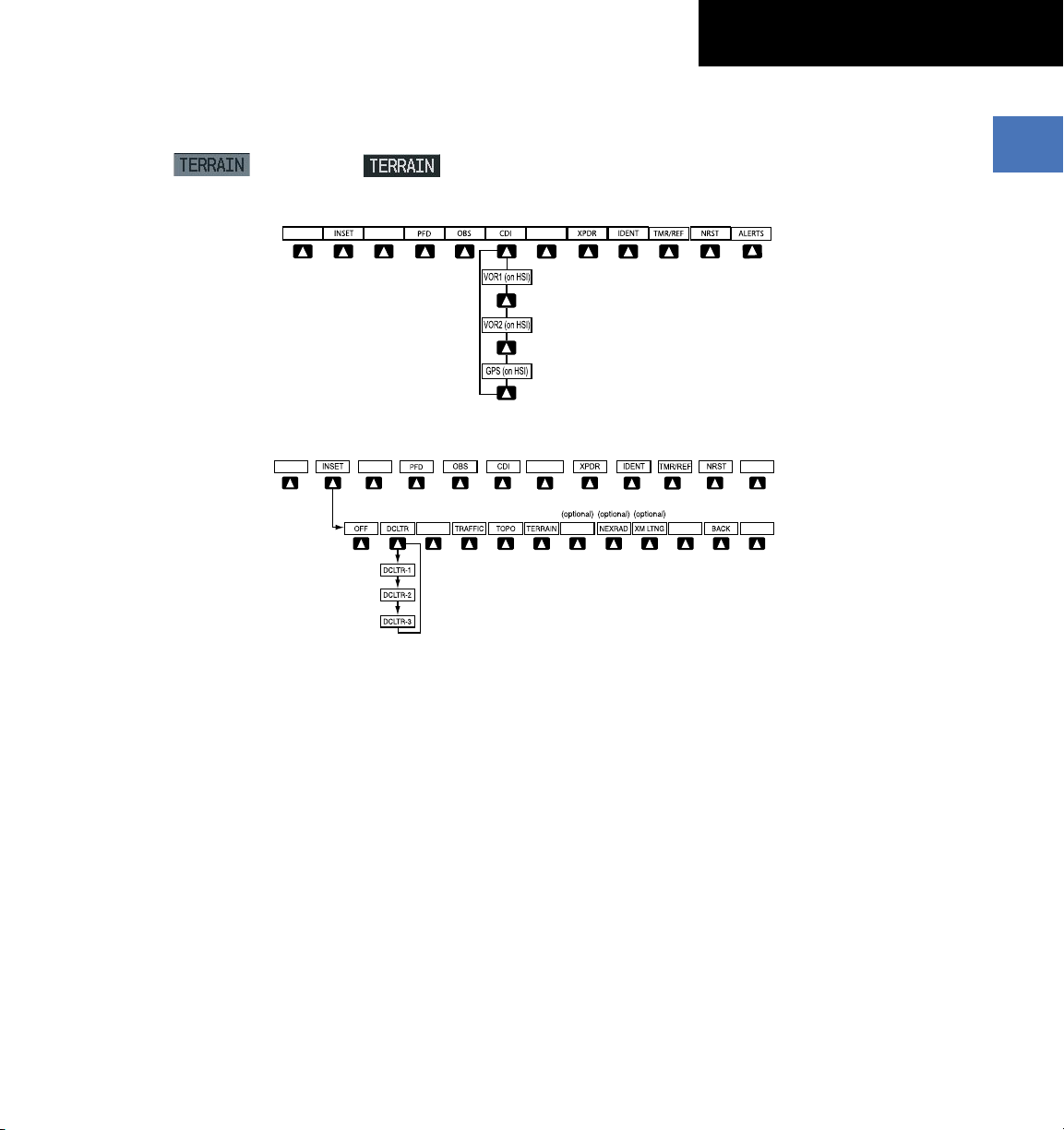
1.3 PFD SOFTKEYS
Press the BACK or OFF Softkey
to return to the top-level softkeys.
ALERTSSTRMSCP
ALERTS
SECTION 1
SYSTEM OVERVIEW
Softkey ON
Softkey OFF
Figure 1-3 PFD Top Level Softkeys
Figure 1-4 INSET Softkeys
INSET – Press to display the Inset Map in the lower
left corner of the PFD.
OFF
– Press to remove the Inset Map.
DCLTR
(3) – Press momentarily to select the desired
amount of map detail. The declutter level appears
adjacent to the DCLTR Softkey.
- No declutter: All map features are visible.
- Declutter – 1: Declutters land data.
- Declutter – 2: Declutters land and SUA data.
- Declutter – 3: Declutters large NAV data
remaining (removes everything except the
active flight plan).
TRAFFIC
190-00567-01 Rev. A
– Press to display traffic on the map.
Garmin G1000 Cockpit Reference Guide for the Columbia 350/400
TOPO
– Press to display topographical data (i.e.,
coastlines, terrain, rivers, lakes, etc.) and
elevation scale on the Inset Map.
TERRAIN
– Press to display terrain information on
the Inset Map.
STRMSCP (optional)
– Press to display the
Stormscope lightning data on the Inset Map
(within a 200 nm radius of the aircraft).
NEXRAD (optional)
– Press to display NEXRAD
weather and coverage information on the Inset
Map.
XM LTNG (optional) –
Press to display XM lightning
information on the Inset Map.
BACK
– Press to return to the previous level softkey
configuration.
1-7
SECTION 1
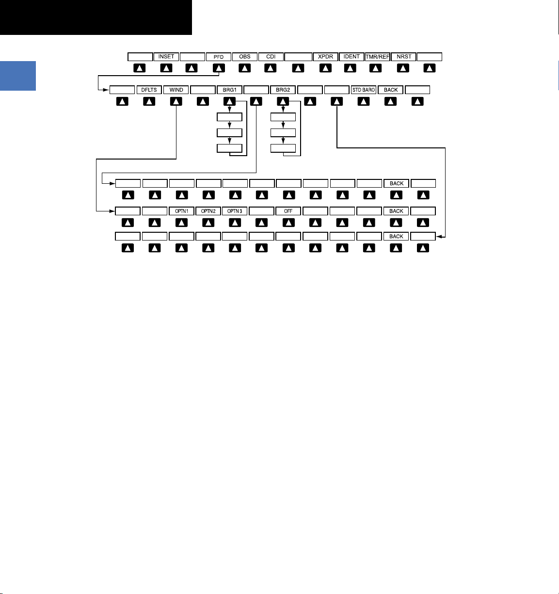
Press the STD BARO or
BACK Softkey to return to
the top-level softkeys
BRG1 (NAV1)
BRG1 (GPS
)
BRG1 (OFF)
ALT UNIT
METERS IN HPA
ALERTS
ALERTS
ALERTS
ALERTS
HSI FRMT
ALERTS
ARC HSI360 HSI
BRG2 (NAV2)
BRG2 (GPS
)
BRG2 (OFF)
SYSTEM OVERVIEW
Figure 1-5 PFD Configuration Softkeys
1-8
PFD – Press to display the additional softkeys for
additional configuration of the PFD.
DFLTS
– Press to reset default settings on the PFD.
WIND
– Displays softkeys to select wind data
parameters.
OP T N 1
– Lo ng it u di na l a nd la te r a l
components.
OPTN 2
OPTN 3
– Total direction and speed.
– Total direction with headwind and
crosswind speed components.
OFF
– Information not displayed.
BRG1 (bearing)
following Nav sources, making the pointer the
indicator for the corresponding source and
displaying the appropriate information.
NAV1
– Displays NAV1 waypoint frequency or
– Press to cycle through the
identifier and DME information in the BRG1
Information Window.
GPS
– Displays GPS waypoint identifier
and GPS distance information in the BRG1
Information Window.
Garmin G1000 Cockpit Reference Guide for the Columbia 350/400
OFF
– Removes the BRG1 Information
Window.
HSI FRMT
– Press to display the HSI formatting
softkeys.
360 HSI
– Press to display the HSI in a 360
degree format.
ARC HSI
format.
BRG2 (bearing)
following Nav sources, making the pointer the
– Press to display the HSI in an arc
– Press to cycle through the
indicator for the corresponding source and
displaying the appropriate information.
NAV2
– Displays NAV2 waypoint frequency or
identifier and DME information in the BRG2
Information Window.
GPS
– Displays GPS waypoint identifier and GPS
distance information in the BRG2 Information
Window.
OFF
– Re m o v e s the BRG2 Information
Window.
190-00567-01 Rev. A
SECTION 1
Press the BACK Softkey to return
to the top-level softkeys.
Press the IDENT or BACK Softkey to return
to the top-level softkeys.
ALERTS
ALERTS
ALERTS
SYSTEM OVERVIEW
ALT UNIT
– Displays softkeys for setting the
altimeter and BARO settings to metric units:
METERS
– When enabled, displays altimeter in
meters.
IN
– Press to display the BARO setting as inches
of mercury.
HPA
– Press to display the BARO setting as
hectopacals.
STD BARO
– Press to set the barometric pressure
to standard pressure.
BACK
– Press to return to the previous level softkeys.
ALERTS
– Press to display the Alerts Window.
OBS – Press to select OBS Mode on the CDI when
navigating by GPS (only available with active leg).
CDI – Press to change navigation mode on the CDI
between GPS, VOR1, and VOR2.
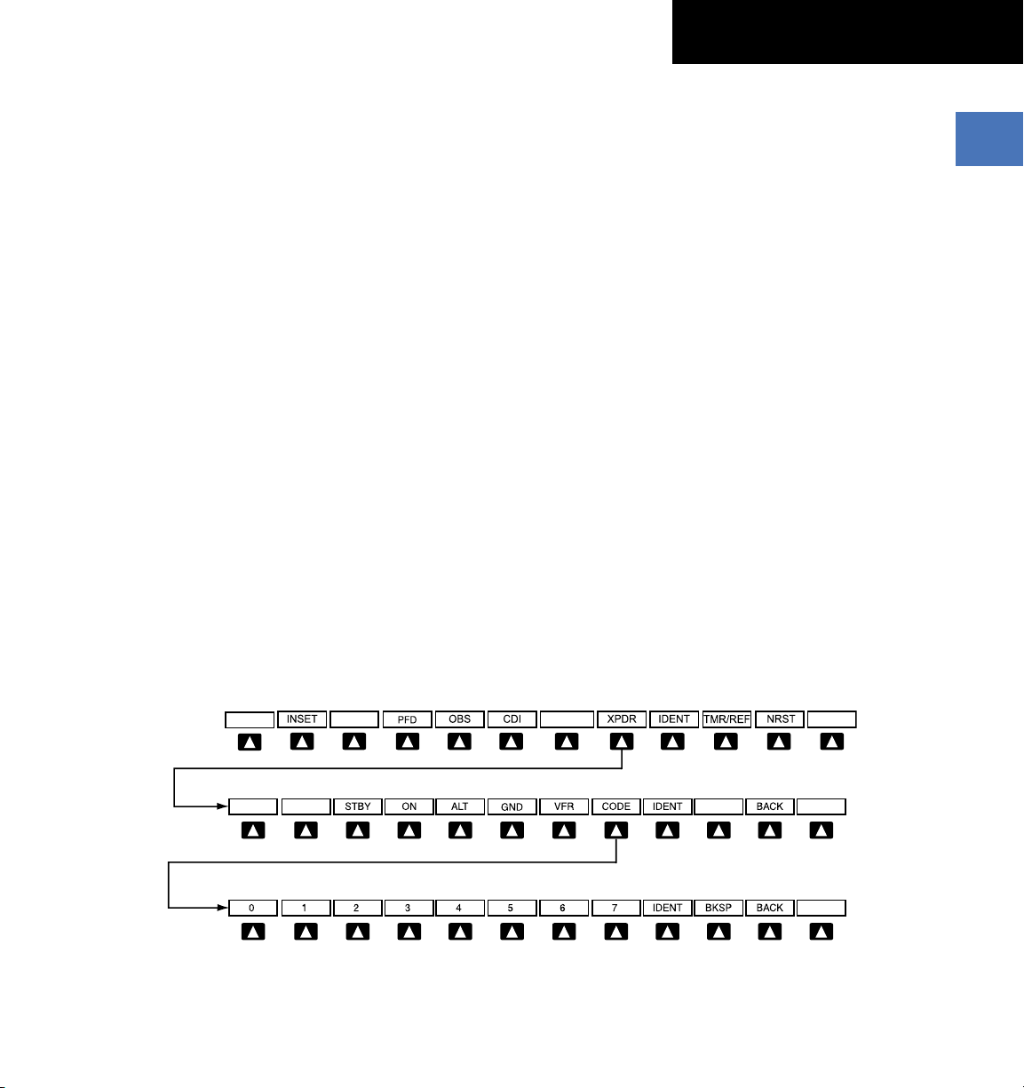
XPDR – Press to display the transponder mode
selection softkeys.
STBY
– Press to select Standby Mode.
ON
– Press to select Mode A.
ALT
– Press to select Altitude Reporting Mode.
GND
– Press to select Ground Mode.
VFR
– Press to automatically squawk 1200 (only
in the U.S.A., refer to ICAO standards for VFR
codes in other countries).
CODE
– Press to display transponder code selection
softkeys 0-7.
0 through 7
IDENT
– Press numbers to enter code.
– Press to provide special aircraft
position identification to Air Traffic Control
(ATC).
BKSP
– Press to remove numbers entered one
at a time.
BACK
– Press to return to the previous level
softkeys.
IDENT
– Press to provide special aircraft position
identification to Air Traffic Control (ATC).
BACK
– Press to return to the previous level
softkeys.
ALERTS
– Press to display the Alerts Window.
IDENT – Press to provide special aircraft position
identification to Air Traffic Control (ATC).
TMR/REF – Press to display the Timer/References
Window.
NRST – Press to display the Nearest Airports
Window.
ALERTS – Press to display the Alerts Window.
190-00567-01 Rev. A
Figure 1-6 XPDR (Transponder) Softkeys
Garmin G1000 Cockpit Reference Guide for the Columbia 350/400
1-9
SECTION 1
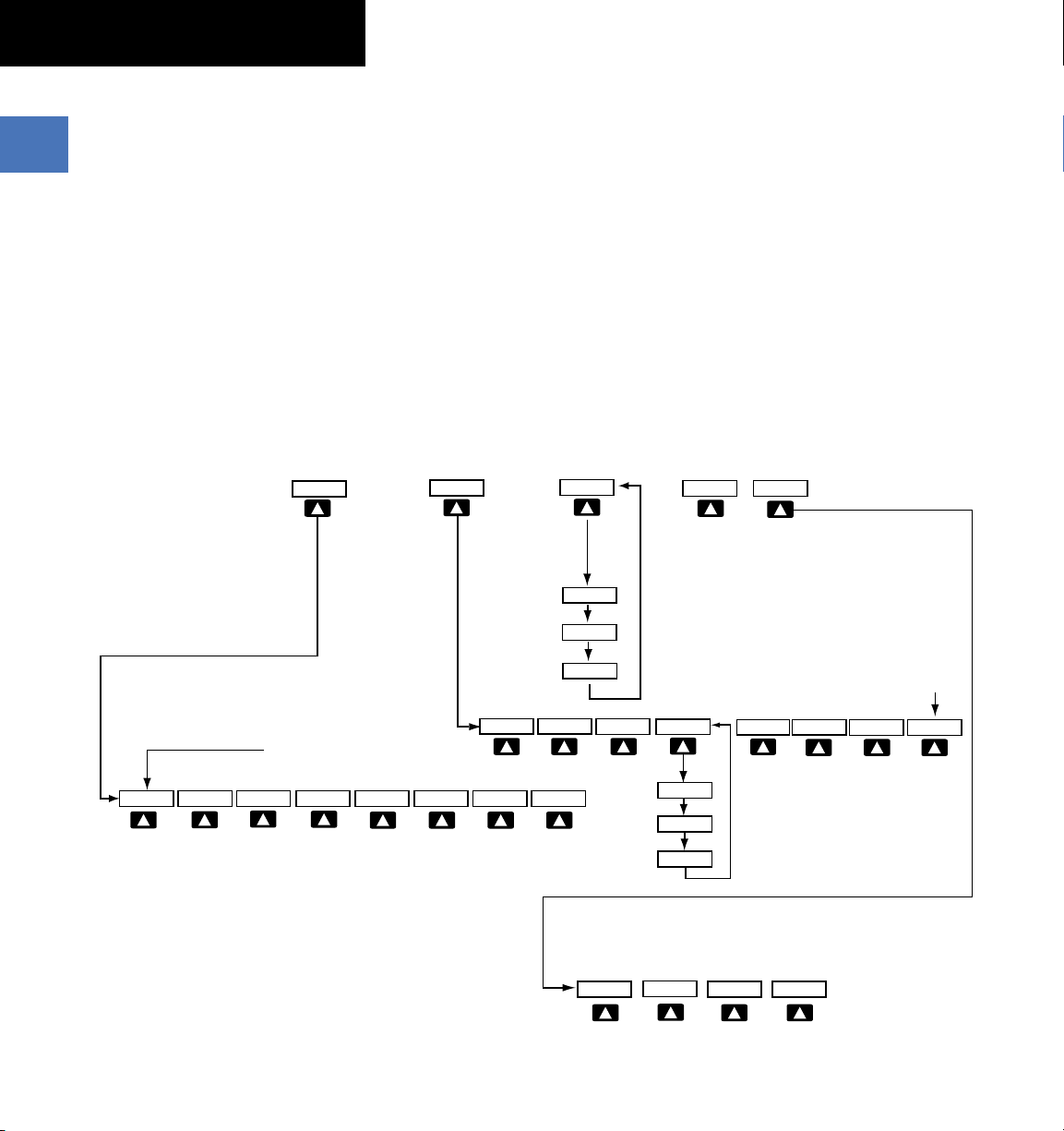
MAP
DCLTR
DCLTR-2
DCLTR-3
DCLTR-1
CHKLIST
EXIT
EMERGCY
SYSTEM
DONE
The DONE Softkey changes to UNDO when the checklist
item is already checked
SYSTEM
(optional)
TRAFFIC
TOPO
BACK
TERRAIN
Press the BACK Softkey on this
level to return to the top softkey level.
STRMSCP
NEXRAD
XM LTNG
(optional) (optional)
(optional)
AIRWAYS
AIRWY LO
AIRWAY HI
AIRWY ON
(Default softkey
is dependant on
the selection mad
e
in the map setup
options)
SHW CHRT
(optional)
Press the SYSTEM Softkey to
return to the default page level
.
DCLTR
SYSTEM
ASSIST
OXYGEN
DEC FUEL
INC FUEL
RST FUEL
CO RST
SYSTEM OVERVIEW
1.4 MFD SOFTKEYS
SYSTEM – Selecting this softkey makes available the
Engine Display functions. Refer to the Engine
Indication System section.
MAP – Pressing this softkey enables the following
softkeys:
TRAFFIC – Pressing this softkey displays/removes
Traffic on the Navigation Map.
TOPO – Pressing this softkey displays or removes
topographic information on the Navigation Map.
TERRAIN – Pressing this softkey displays/removes
terrain and obstacle data on the Navigation Map.
AIRWAYS – Pressing this softkey displays/removes
airways information. The default is dependent on
map setup option selected. Pressing cycles through
all airways displayed (AIRWY ON), low altitude
airways only (AIRWY LO), and high altitude airways
only (AIRWY HI).
STRMSCP (optional) – Pressing this softkey displays/
removes Stormscope lightning data on the Navigation
Map.
NEXRAD (optional) – Pressing this softkey displays/
removes precipitation data on the Navigation Map.
XM LTNG (optional) – Pressing this softkey displays/
removes XM Radio lightning data on the Navigation
Map.
1-10
Figure 1-7 MFD Softkeys
Garmin G1000 Cockpit Reference Guide for the Columbia 350/400
190-00567-01 Rev. A
SECTION 1
SYSTEM OVERVIEW
BACK – Pressing this softkey displays the ENGINE and
MAP top level softkeys.
DCLTR (declutter) – Pressing this softkey removes map
information in three levels.
SHW CHRT (Show Chart)(optional) – Pressing this softkey
displays optional FliteCharts or ChartView charts.
CHKLIST (checklist)(optional) – Pressing the CHKLIST
Softkey displays the Checklist Page.
SYSTEM – Displays engine softkeys.
DONE – Pressing this softkey checks off a checklist item.
If an item is already checked, an UNDO Softkey will
be displayed.
EXIT – Press to exit the checklist.
EMERGCY – Pressing this softkey displays the
emergency checklist.
Nearest Group
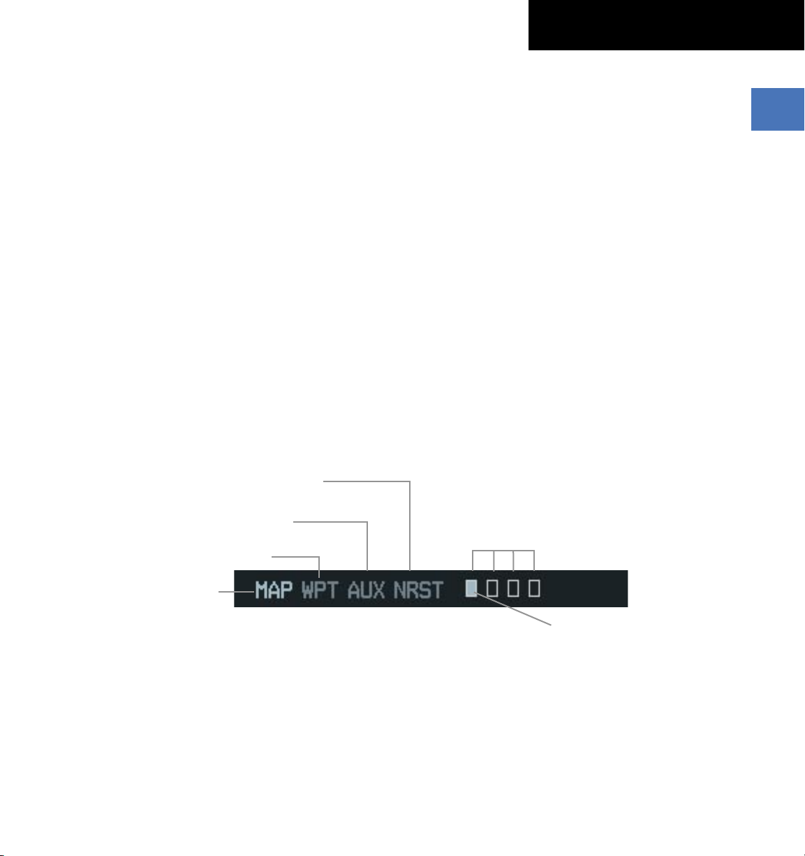
1.5 MFD PAGE GROUPS
1)
Turn the large
group is selected.
2)
Turn the small
group. See Figure 1-8.
FMS
Knob until the desired page
FMS
Knob to select pages within the
Map Page Group
190-00567-01 Rev. A
Auxiliary Page Group
Waypoint Page Group
Garmin G1000 Cockpit Reference Guide for the Columbia 350/400
Number of Pages in Current
Figure 1-8 Page Group Icon
Group
Selected Page
1-11

SECTION 1
SYSTEM OVERVIEW
1.6 VERTICAL NAVIGATION
In WAAS capable installations, one of two altitude
sources is used by the G1000 when giving vertical
navigation guidance. WAAS GPS altitude is used when
giving guidance for a WAAS approach. Baro corrected
altitude is used when vertical guidance is given in all other
situations and in non-WAAS systems.
The G1000 system can use altitude constraints
associated with lateral waypoints to give guidance for
vertical navigation. These altitudes are, depending on the
specific instance, entered by the pilot or retrieved from the
published altitudes in the navigation database.
The navigation database only contains altitudes
for procedures that call for “Cross at” altitudes. If the
procedure states “Expect to cross at,” then the altitude will
not be in the database. In this case the altitude may be
entered manually.
NOTE: All arrival procedure altitudes contained in
the navigation database are for turbojet aircraft only.
Alter or enter altitudes as desired to comply with the
ATC clearance.
When activating or loading an arrival or approach
procedure into an active flight plan, the VNV ‘ALT’ fields
will be populated with any altitudes that can be retrieved
from the navigation database.
Since altitudes loaded with an arrival procedure are
published only for turbojet aircraft, the altitudes are
displayed as white text indicating that the altitudes are
displayed for reference only. An arrival waypoint altitude
may be used (or “designated”) as is, or changed to a
different altitude. An altitude is designated by pressing the
FMS Knob and turning the large FMS Knob to place the
cursor on the desired altitude and pressing the ENT Key or
entering a different value and pressing the ENT Key. The
altitude will now be displayed as light blue text, indicating
that the altitude is now designated to give vertical speed
and deviation guidance.
Approach waypoint altitude constraints are automatically
designated for use when the approach is loaded. These
altitudes will be displayed as light blue text indicating the
altitudes will be used in vertical guidance calculations.
Waypoint altitude constraints may be designated up to, but
not including the FAF. The FAF will always be a “reference
only” altitude and cannot be designated, unless the selected
approach does not provide vertical guidance. In this case,
the FAF altitude can be designated.
Altitudes that have been designated for use in vertical
guidance may also be made “non-designated” by placing the
cursor over the desired altitude and pressing the CLR Key.
Other displayed altitudes may change due to re-calculations
or rendered invalid as a result of manually changing an
altitude to a non-designated altitude.
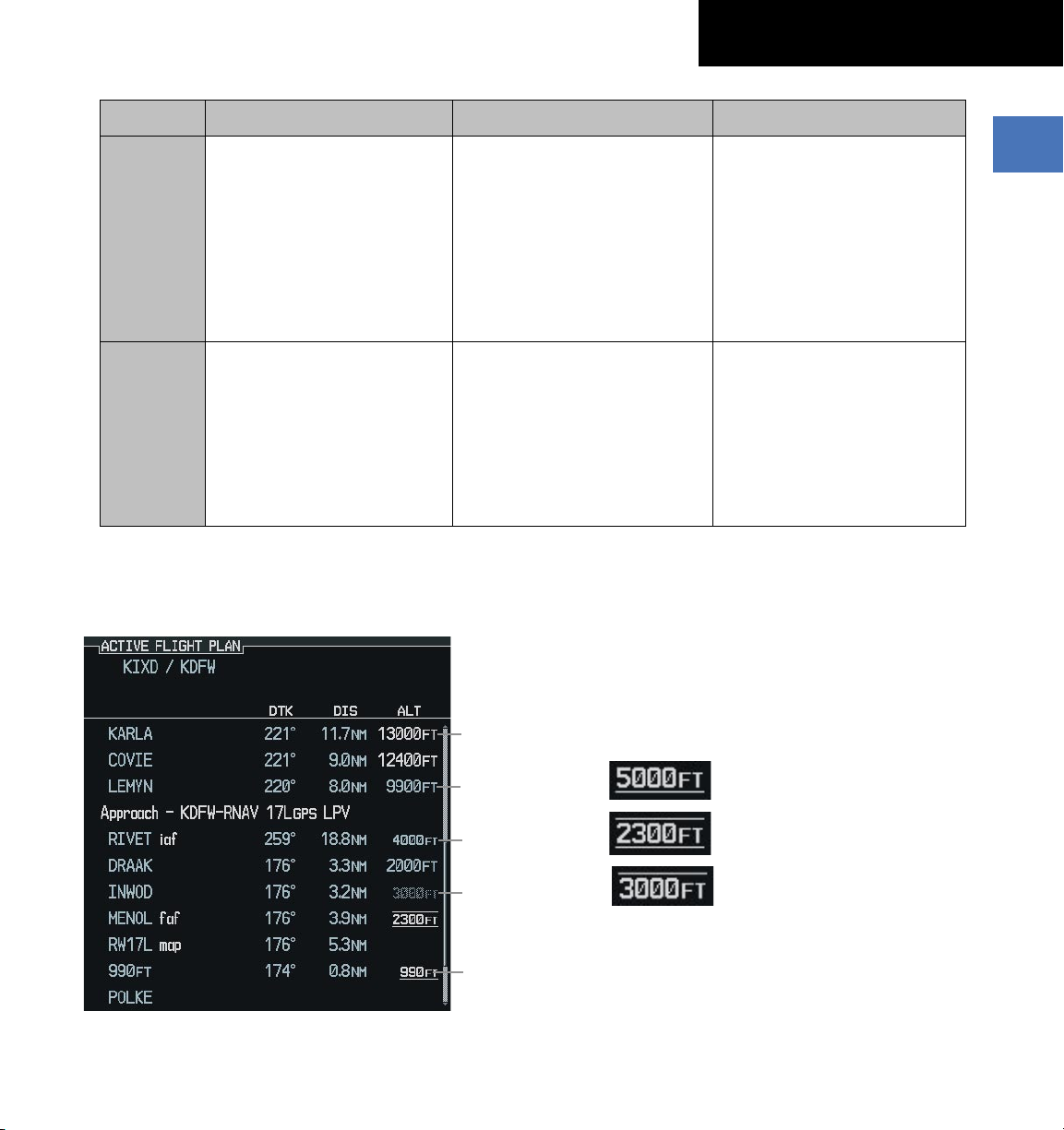
To help interpret the meanings of how the altitudes are
presented, keep the following points in mind:
• When the altitude is displayed in light blue,
the system is using that altitude (designated) to
determine vertical speed and deviation guidance.
• When the altitude is displayed in white, it is not being
used by the system (non-designated) to determine
the vertical speed and deviation guidance.
• An altitude displayed as small text is an altitude that
is published in the navigation database.
• Altitudes displayed as a light blue subdued text
cannot be used in the current vertical navigation
calculations.
1-12
Garmin G1000 Cockpit Reference Guide for the Columbia 350/400
190-00567-01 Rev. A
SECTION 1
SYSTEM OVERVIEW
White Text Light Blue Text Light Blue Subdued Text
Large Text
Altitude calculated by the system
estimating the altitude of the
aircraft as it passes over the
navigation point. This altitude
is provided as a reference and
is not designated to be used in
determining vertical speed and
Altitude has been entered by the
pilot. Altitude is designated for
use in giving vertical speed and
deviation guidance. Altitude does
not match the published altitude
in navigation database or no
published altitude exists.
deviation guidance.
Small Text
Altitude is not designated to
be used in determining vertical
speed and deviation guidance.
Altitude has been retrieved from
the navigation database and is
provided as a reference.
Altitude is designated for use in
giving vertical speed and deviation
guidance. Altitude has been
retrieved from the navigation
database or has been entered by
the pilot and matches a published
altitude in the navigation database.
Table 1-1 VNV Altitude Text Size and Color
Refer to Figure 1-8 and Table 1-1 for more detail
regarding the significance of text size and color.
Large White
The system cannot use this altitude
in determining vertical speed and
deviation guidance.
The system cannot use this altitude
in determining vertical speed and
deviation guidance.
Some altitudes retrieved from the database have
associated restrictions indicating to stay ‘At’, ‘At or Above’,
or ‘At or Below’ a specific altitude. These restrictions are
indicated using a ‘bar’ above and/or below the appropriate
altitude as shown in Figure 1-9.
Text
Figure 1-9 VNAV Altitudes
190-00567-01 Rev. A
Large Light
Blue Text
Small Light
Blue Text
Small Light
Blue Subdued
Text
Small White
Text with
Altitude
Restriction
Bar
Figure 1-10
See Section 7 - Navigation, for a sample flight plan
which further illustrates vertical navigation in more
Stay AT or ABOVE 5,000 ft
Stay AT 2,300 ft
Stay AT or BELOW 3,000 ft
Altitude Restrictions
detail.
Garmin G1000 Cockpit Reference Guide for the Columbia 350/400
1-13
SECTION 1
SYSTEM OVERVIEW
1.7 BACKLIGHTING
When system power is turned off, all manual
backlighting settings will return to the factory default
settings.
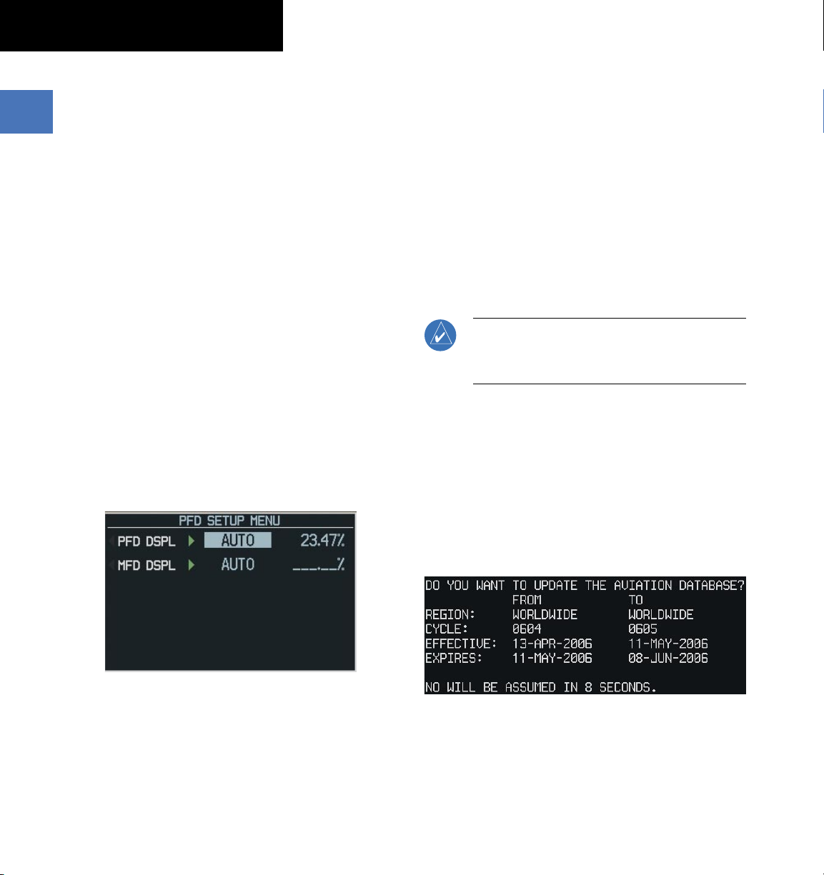
Manually adjust the backlight for the PFD
and MFD:
1)
Press the MENU Key on the PFD to display the PFD
Setup Menu Window.
2)
Press the small FMS Knob to activate the cursor.
‘PFD DSPL > AUTO’ is now highlighted.
3)
Tur n the small FMS Knob to displ ay the
selection window.
4)
Turn the FMS Knob to select ‘MANUAL’, then press
the ENT Key.
5)
With the intensity value now highlighted, turn
the small FMS Knob to select the desired
backlighting.
6)
Turn the large FMS Knob to highlight ‘MFD DSPL
> AUTO’ and repeat steps 3 through 5.
1.8 DATABASE UPDATES
The G1000 System uses Secure Digital (SD) cards
to load and store various types of data. For basic flight
operations, SD cards are required for database storage
as well as Jeppesen aviation and ChartView database
updates.
The following procedures pertain to updating the
G1000 system with SD cards as outlined in Appendix B of
the G1000 Columbia 350/400 Pilot’s Guide.
Jeppesen Aviation Database
NOTE: After the aviation database is installed,
the card may be removed after loading the
update to each LRU.
Updating the Jeppesen aviation database:
1)
With the G1000 System OFF, insert the SD card
containing the aviation database update into the
top card slot of the PFD to be updated (Label of SD
card facing left).
2)
Turn the G1000 System ON. A prompt similar to
the following is displayed in the upper left corner
of the PFD:
1-14
Figure 1-11 PFD Setup Menu Window
Garmin G1000 Cockpit Reference Guide for the Columbia 350/400
Figure 1-12 Database Update Prompt
3)
Press the ENT Key to start the database update. A
prompt similar to the following is displayed:
190-00567-01 Rev. A
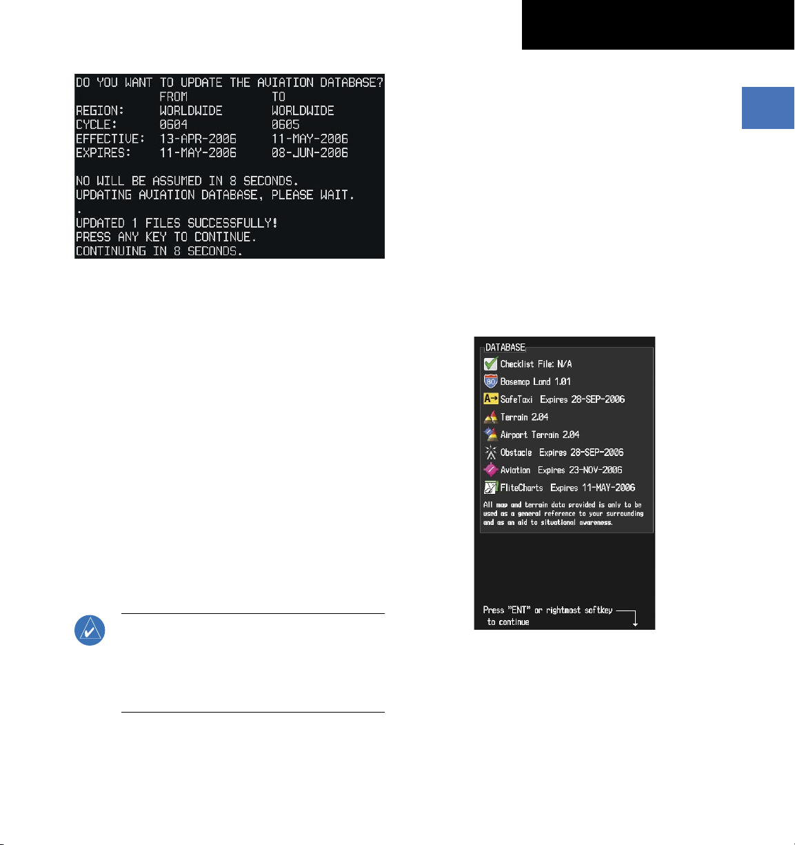
Figure 1-13 Database Update Confirmation
4)
After the update completes, the PFD starts in normal
mode.
5)
Turn the G1000 System OFF and remove the SD
card.
6)
Repeat steps 1 through 4 for the MFD. The MFD
and PFD databases are now updated. Remove the
SD card when finished.
SECTION 1
SYSTEM OVERVIEW
1)
Insert one SD card in the bottom card slot of the
MFD and one in the bottom card slot of the PFD.
The SD card containing the ChartView or FliteCharts
database must be inserted into the bottom slot on
the MFD.
2)
Apply power to the G1000 System. View the MFD
power-up splash screen. Check that the databases
are initialized and displayed on the scrolling
window of the splash screen. When updating the
terrain and FliteCharts databases, an ‘in progress’
message may be seen. If this message is present,
wait for the system to finish loading before verifying
the correct databases are initialized, then proceed
to step 3.
7)
Verify that the correct update cycle is loaded during
startup of the MFD.
Garmin Databases
Since these databases are not stored internally in
the MFD or PFD, a Supplemental Data Card containing
identical database versions must be kept in each display
unit.
NOTE: The data contained in the terrain and
obstacle databases comes from government
agencies. Garmin accurately processes and
cross-validates the data, but cannot guarantee
the accuracy and completeness of the data.
190-00567-01 Rev. A
Garmin G1000 Cockpit Reference Guide for the Columbia 350/400
Figure 1-14 Power-Up Splash Screen Window
3)
Acknowledge the Power-up Page agreement by
pressing the
4)
At the MAP – NAVIGATION MAP Page, select the
MAP
Softkey and check to make sure that the
and
TERRAIN
ENT
Key or the right most softkey.
Softkeys are available (not dimmed)
and other database features are functioning.
5)
Power down the G1000.
TOPO
1-15

SECTION 1
SYSTEM OVERVIEW
Blank Page
1-16
Garmin G1000 Cockpit Reference Guide for the Columbia 350/400
190-00567-01 Rev. A
 Loading...