

Garmin 0061100 Users Manual

GNS 430 Pilots Guide and Reference
GARMIN Corporation
1200 E. 151stStreet
OLATHE, KS 66062
Dwg. Number 190-00140-00 REV. F
ARCHIVE FILE: 190-00140-00_0F
FILE TYPE: QuarkXPress for Windows
CONFIDENTIAL
This document and the specifications
contained herein are the property of
GARMIN Corporation and may not be
reproduced or used in whole or in part
as the basis for manufacturing or sale
of products without written permission
of GARMIN Corporation.
APPROVALS DATE
DRAWN K. Otterman 12/1/98
CHKD. J W D 12/1/98
PROJ. MGR. T L J 12/1/98
RELEASED M L R 12/8/98
REV DATE DESCRIPTION OF CHANGE ECO#
A 12/1/98 INITIAL RELEASE N/A
B 4/30/99 Update to conform to recent software changes 10944
C 6/24/99 Reference Update for ECO #11294 11294
D 7/28/99 Update for software 2.10 11507
E 4/14/00 Update for software 2.15 13131
F 7/24/00
Update pwr on, wind vctr, crossfill, DME, fuel plan
13800

430MANF.qxd 7/24/00 4:43 PM Page ii

INTRODUCTION
Foreword
i
GARMIN International, Inc., 1200 East 151st Street, Olathe, Kansas 66062 USA
Tel: 913/397.8200 Fax: 913/397.8282
GARMIN (Europe) LTD, Unit 5, The Quadrangle, Abbey Park, Romsey, Hampshire S051 9AQ, UK
Tel: 44/1794.519944 Fax: 44/1794.519222
GARMIN (Asia) Corp., No. 68, Jangshu 2nd Road., Shijr, Taipei County, Taiwan
Tel: 886/2.2642.9199 Fax: 886/2.2642-9099
Website Address: www.garmin.com
© 1998- 2000 GARMIN Corporation. All rights reserved. Except as expressly provided herein, no part of this manual may be reproduced, copied, transmitted, disseminated, downloaded or stored in any storage medium, for any purpose without
the express prior written consent of GARMIN Corporation. GARMIN Corporation
hereby grants permission to download a single copy of this manual and of any revision to this manual onto a hard drive or other electronic storage medium to be
viewed and to print one copy of this manual or of any revision hereto, provided that
such electronic or printed copy of this manual or revision must contain the complete text of this copyright notice and provided further that any unauthorized commercial distribution of this manual or any revision hereto is strictly prohibited.
Information in this document is subject to change without notice. GARMIN reserves
the right to change or improve their products and to make changes in the content of
this material without obligation to notify any person or organization of such changes
or improvements.
July 2000 190-00140-00 Rev. F
Visit the GARMIN website for the latest
updates and supplemental information concerning the operation of this and other
GARMIN products.
GARMIN, GNS 430, Spell’N’Find, AutoLocate
and PhaseTrac12 are trademarks of GARMIN
and may only be used with permission.
NavData® is a registered trademark of
Jeppesen, Inc.
This manual incorporates changes included in
Main System Software version 2.17. It
includes information contained in the
Addendum to Pilot's Guide P/N 190-00140-11
Rev A, covering crossfill and fuel management
operation for software 2.11 and above.
430MANF.qxd 7/24/00 4:43 PM Page i

CAUTION
The Global Positioning System is operated by the United States government, which
is solely responsible for its accuracy and maintenance. The system is subject to changes
which could affect the accuracy and performance of all GPS equipment. Although the
GARMIN GNS 430 is a precision electronic NAVigation AID (NAVAID), any NAVAID
can be misused or misinterpreted and therefore become unsafe.
Use the GNS 430 at your own risk. To reduce the risk of unsafe operation,
carefully review and understand all aspects of this Owner’s Manual and the Flight
Manual Supplement, and thoroughly practice basic operation prior to actual use. When
in actual use, carefully compare indications from the GNS 430 to all available navigation
sources, including the information from other NAVAIDS, visual sightings, charts, etc.
For safety, always resolve any discrepancies before continuing navigation.
The altitude calculated by the GNS 430 is geometric height above mean sea level
and could vary significantly from altitude displayed by pressure altimeters in aircraft.
GPS accuracy may be degraded by the U.S. Department of Defense-imposed Selective
Availability (SA) program. With “SA” on, GPS altitude may be in error by several hundred feet. Never use GPS altitude for vertical navigation.
GPS receivers operate by receiving and decoding very low power radio signals
broadcast by satellites. It is possible that in some situations other radio equipment or
electronic equipment used in close proximity to a GPS receiver may create electromagnetic interference (EMI) which may affect the ability of the GPS receiver to receive and
decode the satellite signals. In such event, the interference may be reduced or eliminated by switching off the source of interference or relocating equipment.
The Jeppesen database incorporated in the GNS 430 must be updated regularly in
order to ensure that its information is current. Updates are released every 28 days. A
database information packet is included in your GNS 430 package.
Pilots using an out-of-date database do so entirely at their own risk.
ii
NOTE: This device complies with Part 15 of the
FCC limits for Class B digital devices. This equipment generates, uses, and can radiate radio frequency energy and, if not installed and used in
accordance with the instructions, may cause harmful interference to radio communications.
Furthermore, there is no guarantee that interference will not occur in a particular installation.
If this equipment does cause harmful interference, the user is encouraged to try to correct the
interference by relocating the equipment or connecting the equipment to a different circuit than the
affected equipment. Consult an authorized dealer or
other qualified avionics technician for additional help
if these remedies do not correct the problem.
Operation of this device is subject to the following conditions: (1) This device may not cause harmful interference, and (2) this device must accept
any interference received, including interference
that may cause undesired operation.
The GARMIN GNS 430 does not contain any
user-serviceable parts. Repairs should only be made
by an authorized GARMIN service center.
Unauthorized repairs or modifications could void
your warranty and authority to operate this device
under Part 15 regulations.
INTRODUCTION
Cautions
430MANF.qxd 7/24/00 4:43 PM Page ii

INTRODUCTION
Accessories and
Packing List
Accessories & Packing List
Congratulations on choosing the finest, most advanced panel mount IFR
navigation/communication system available. The GNS 430 represents GARMIN’s
commitment to provide accurate, easy-to-use avionics for all of your flying needs.
Before installing and getting started with your new system, please check to see
that your package includes the following items. If any parts are missing or damaged, please see your GARMIN dealer immediately.
Standard Package:
• GNS 430 Unit & NavData® Card
• Installation Rack & Connectors
• Pilot’s Guide & Quick Reference Guide
• Database Subscription Packet
• Warranty Registration Card
Your GARMIN dealer will perform the installation and configuration of your
new GNS 430. After installation, the NavData® card will already be installed into
the correct slot on the front of the unit (see Appendix A). The GNS 430 will be
secured in the installation rack with the proper wiring connections performed.
Have your dealer answer any questions you may have about the installation—such
as location of antennas or any connections to other equipment in the panel.
iii
To obtain accessories for your GNS 430,
please contact your GARMIN dealer.
The GNS 430 display lens is coated with
a special anti-reflective coating which is
very sensitive to skin oils, waxes and
abrasive cleaners. It is very important to
clean the lens using an eyeglass lens
cleaner which is specified as safe for antireflective coatings (one suitable product is
Wal-Mart
®
Lens Cleaner) and a clean,
lint-free cloth.
Help us better support you by completing
our online registration today!
Registration ensures you will be notified
of product updates, new products and
provides lost or stolen unit tracking. Have
the serial number of your GNS 430 handy
and connect to our website
(www.garmin.com). Look for the Product
Registration link on the home page.
430MANF.qxd 7/24/00 4:43 PM Page iii

PROCEDURES
Approach Examples
5
INTRODUCTION
Warranty
GARMIN is fully committed to your satisfaction as a customer. If you have any questions
regarding the GNS 430, please contact our
customer service department at:
GARMIN International, Inc.
1200 East 151st Street
Olathe, KS 66062-3426
(913) 397-8200
FAX (913) 397-8282
To obtain warranty service, call the GARMIN
Customer Service department for a returned
merchandise tracking number. The unit should
be securely packaged with the tracking number clearly marked on the outside of the package, and sent freight prepaid and insured to a
GARMIN warranty service station. A copy of
the original sales receipt is required as proof
of purchase for warranty repairs. GARMIN
retains the exclusive right to repair or replace
the unit or software or offer a full refund of
the purchase price at its sole discretion. SUCH
REMEDY SHALL BE YOUR SOLE AND
EXCLUSIVE REMEDY FOR ANY BREACH
OF WARRANTY.
GARMIN Corporation warrants this product to be free from defects in materials
and workmanship for one year from the date of purchase. GARMIN will, at its sole
option, repair or replace any components that fail in normal use. Such repairs or
replacement will be made at no charge to the customer for parts or labor. The customer is, however, responsible for any transportation costs. This warranty does not
cover failures due to abuse, misuse, accident or unauthorized alteration or repairs.
THE WARRANTIES AND REMEDIES CONTAINED HEREIN ARE
EXCLUSIVE, AND IN LIEU OF ALL OTHER WARRANTIES EXPRESSED OR
IMPLIED, INCLUDING ANY LIABILITY ARISING UNDER WARRANTY OF
MERCHANTABILITY OR FITNESS FOR A PARTICULAR PURPOSE, STATUTORY OR OTHERWISE. THIS WARRANTY GIVES YOU SPECIFIC LEGAL
RIGHTS, WHICH MAY VARY FROM STATE TO STATE.
IN NO EVENT SHALL GARMIN BE LIABLE FOR ANY INCIDENTAL,
SPECIAL, INDIRECT OR CONSEQUENTIAL DAMAGES, WHETHER
RESULTING FROM THE USE, MISUSE OR INABILITY TO USE THIS
PRODUCT OR FROM DEFECTS IN THE PRODUCT. SOME STATES DO NOT
ALLOW THE EXCLUSION OF INCIDENTAL OR CONSEQUENTIAL
DAMAGES, SO THE ABOVE LIMITATIONS MAY NOT APPLY TO YOU.
iv
430MANF.qxd 7/24/00 4:43 PM Page iv

INTRODUCTION
Table of Contents
PART ONE: INTRODUCTION
Foreword . . . . . . . . . . . . . . . . . . . . . . . . . . . . . . . . . . . . . . . . . . . . . . . . . . . . . . . .i
Cautions . . . . . . . . . . . . . . . . . . . . . . . . . . . . . . . . . . . . . . . . . . . . . . . . . . . . . . . .ii
Accessories/Packing List . . . . . . . . . . . . . . . . . . . . . . . . . . . . . . . . . . . . . . . . . . . .iii
Warranty . . . . . . . . . . . . . . . . . . . . . . . . . . . . . . . . . . . . . . . . . . . . . . . . . . . . . . . .iv
Table of Contents . . . . . . . . . . . . . . . . . . . . . . . . . . . . . . . . . . . . . . . . . . . . . . . .v-vi
Takeoff Tour . . . . . . . . . . . . . . . . . . . . . . . . . . . . . . . . . . . . . . . . . . . . . . . . . . .1-20
PART TWO: REFERENCE
Section 1: Communicating with the GNS 430 . . . . . . . . . . . . . . . . . . . . . . . . . . .21
COM and VLOC frequencies
Active and standby frequencies
Section 2: NAV Page Group (GPS navigation) . . . . . . . . . . . . . . . . . . . . . . . . . . .27
Using page groups and selecting the desired page
Using the default NAV and map pages
Section 3: Direct-to Navigation . . . . . . . . . . . . . . . . . . . . . . . . . . . . . . . . . . . . . .49
Using the Dkey
Section 4: Flight Plans (
F
key and FPL page group) . . . . . . . . . . . . . . . . . . .54
Creating and using flight plans
Retrieving and editing stored flight plans
Section 5: Approaches, Departures and Arrivals (
P
key) . . . . . . . . . . . . . . . .66
Selecting and flying non-precision/precision approaches
Selecting and using departures (SIDs) and arrivals (STARs)
v
CONVENTIONS USED IN THIS MANUAL
A circled number (e.g.,”
”) will appear next
to many of the illustrations shown along the
side of a page. This number refers back to a
specific step on the same page (or in rare
instances, to a step on the following page).
When more than one option is possible within
a procedure, the procedures are described
using an “a”/”b” convention with the same
numbering (e.g., “3a” and “3b” for two step#3
options). This same convention is used when
multiple procedures are listed on the same
page and illustrations are provided for the
steps described in one or both procedures
(e.g.,”
a” and ”b”).
A highlighted “NOTE” area appears on many
pages to point out additional information or
items of particular importance related to a
given subject.
430MANF.qxd 7/24/00 4:43 PM Page v

PROCEDURES
Approach Examples
5
INTRODUCTION
Table of Contents
Section 6: WPT Page Group (Waypoint/database information) . . . . . . . . . . . . . .94
Finding and viewing airport location, runway and frequency data
Finding and viewing navaid information
Creating user-defined waypoints
Section 7: NRST Page Group (Nearest airports, etc.) . . . . . . . . . . . . . . . . . . . . 119
Viewing nearest listings for airports, navaids and airspaces
Displaying frequencies for nearest flight service station (FSS)
and center (ARTCC/FIR)
Section 8: VLOC (VOR/Localizer/Glideslope) Receiver Operations. . . . . . . . . 131
Section 9: AUX page group (Flight Planning and Unit Settings) . . . . . . . . . . . .135
Section 10: Messages, Abbreviations & Navigation Terminology . . . . . . . . . . .163
Appendix A: NavData®Card Use . . . . . . . . . . . . . . . . . . . . . . . . . . . . . . . . . . .177
Appendix B: Specifications . . . . . . . . . . . . . . . . . . . . . . . . . . . . . . . . . . . . . . . .178
Appendix C: Map Datums . . . . . . . . . . . . . . . . . . . . . . . . . . . . . . . . . . . . . . . . .179
Appendix D: Troubleshooting Q & A . . . . . . . . . . . . . . . . . . . . . . . . . . . . . . . .181
Appendix E: Index . . . . . . . . . . . . . . . . . . . . . . . . . . . . . . . . . . . . . . . . . . . . . . .187
vi
To quickly and easily locate information
on specific tasks, please refer to the Index
on page 187.
430MANF.qxd 7/24/00 4:43 PM Page vi
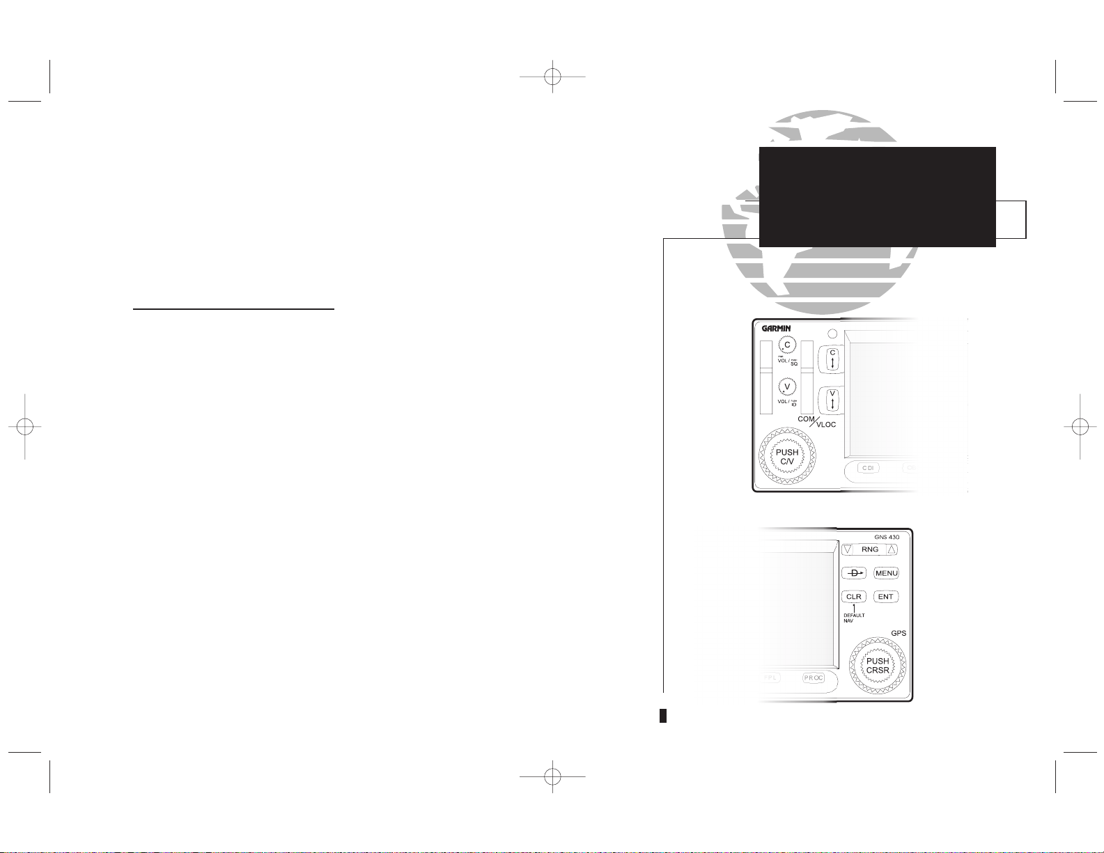
TAKEOFF TOUR
Key and Knob
Functions
Key and Knob Functions
The GNS 430 is designed to make operation as simple as possible. The key and
knob descriptions on the next three pages provide a general overview of the primary function(s) for each key and knob. This Takeoff Tour section is intended to provide a brief overview of the primary functions of your GNS 430. Experiment with
the unit and refer to the Reference sections for more information.
Left-hand Keys and Knobs
The COM power/volume knob controls unit power and communications
radio volume. Press momentarily to disable automatic squelch control.
The VLOC volume knob controls audio volume for the selected VOR/
Localizer frequency. Press momentarily to enable/disable the ident tone.
The large left knob (COM/VLOC) is used to tune the megahertz (MHz)
value of the standby frequency for the communications transceiver
(COM) or the VLOC receiver, whichever is currently selected by the
tuning cursor.
The small left knob (COM/VLOC) is used to tune the kilohertz (kHz)
value of the standby frequency for the communications transceiver
(COM) or the VLOC receiver, whichever is currently selected by the
tuning cursor. Press this knob momentarily to toggle the tuning cursor
between the COM and VLOC frequency fields.
The COM flip-flop key is used to swap the active and standby COM
frequencies. Press and hold to select emergency channel (121.500 MHz).
The VLOC flip-flop key is used to swap the active and standby VLOC
frequencies (i.e., make the selected standby frequency active).
1
h
f
W
V
k
j
Left-hand Keys and Knobs
Right-hand Keys and Knobs
430MANF.qxd 7/24/00 4:43 PM Page 1
PROCEDURES
Approach Examples
5
Right-hand Keys and Knobs
The range key allows you to select the desired map scale. Use the up
arrow side of the key to zoom out to a larger area, or the down arrow side
to zoom in to a smaller area.
The direct-to key provides access to the direct-to function, which allows
you to enter a destination waypoint and establishes a direct course to the
selected destination. See Section 3.
The menu key displays a context-sensitive list of options.
This options list allows you to access additional features or make settings
changes which relate to the currently displayed page.
The clear key is used to erase information or cancel an entry. Press and
hold this key to immediately display the Default Navigation Page (see
pages 12 and 28), regardless of which page is currently displayed.
The enter key is used to approve an operation or complete data entry.
It is also used to confirm information, such as during power on.
The large right knob (CRSR) is used to select between the various page
groups: NAV, WPT, AUX or NRST. With the on-screen cursor enabled,
the large right knob allows you to move the cursor about the page.
The small right knob (CRSR) is used to select between the various pages
within one of the groups listed above. Press this knob momentarily to
display the on-screen cursor. The cursor allows you to enter data and/or
make a selection from a list of options.
2
Data is entered using the large and small
knobs. Experiment with them to become
efficient at entering data. This will greatly
reduce the amount of time spent operating
the GNS 430 in flight.
TAKEOFF TOUR
Key and Knob
Functions
D
m
c
E
d
a
R
430MANF.qxd 7/24/00 4:43 PM Page 2
TAKEOFF TOUR
Key and Knob
Functions
Bottom Row Keys
The CDI key is used to toggle which navigation source (GPS or VLOC) provides output to an external HSI or CDI.
The OBS key is used to select manual or automatic sequencing of waypoints.
Pressing the OBS key selects OBS mode, which will retain the current “active
to” waypoint as your navigation reference even after passing the waypoint (i.e.,
prevents sequencing to the next waypoint). Pressing the OBS key again will
return to normal operation, with automatic sequencing of waypoints. Whenever OBS mode is selected, you may set the desired course to/from a waypoint
using the OBS Page, or an external OBS selector on your HSI or CDI.
The message key is used to view system messages and to alert you to important warnings and requirements. See Sections 10 and 9 for more information
on messages and unit settings.
The flight plan key allows you to create, edit, activate and invert flight plans,
as well as access approaches, departures and arrivals. A closest point to flight
plan feature is also available from the flight plan key. See Section 4 for more
information on flight plans.
The procedures key allows you to select and remove approaches, departures
and arrivals from your flight plan. When using a flight plan, available procedures for your departure and/or arrival airport are offered automatically.
Otherwise, you may select the desired airport, then the desired procedure.
3
Whenever the GNS 430 is displaying a list of
information that is too long for the display
screen, a scroll bar will appear along the
right-hand side of the display. The scroll bar
graphically indicates the number of additional
items available within the selected category.
Simply press the small right knob (
a
) to
activate the cursor and rotate the large right
knob (
d
) to scroll through the list.
C
O
F
M
P
}
scroll bar
430MANF.qxd 7/24/00 4:43 PM Page 3
PROCEDURES
Approach Examples
5
TAKEOFF TOUR
Power On
The GARMIN GNS 430 provides you accurate navigational data and communication capability, along with non-precision and precision approach certification in
the IFR environment. The Takeoff Tour is designed to familiarize you with the
operation of the GNS 430 — including powering up the unit, changing frequencies, entering data, performing a simple direct-to, selecting IFR procedures and
provides a limited introduction to using flight plans. In addition, this section briefly
covers the default navigation, map and frequency pages available as part of the
NAV page group. These pages will be used for most of your in-flight navigation.
The Takeoff Tour assumes that the unit and antennas have been properly
installed and you have not changed any of the GNS 430’s default settings. If you
have changed any of the factory default settings (position format, units of measure,
selectable fields, etc.), the pictures shown here may not exactly match what you see
on your GNS 430. Prior to using your GNS 430 for the first time, we recommend
that you taxi to a location that is well away from buildings and other aircraft so the
unit can collect satellite data without interruption.
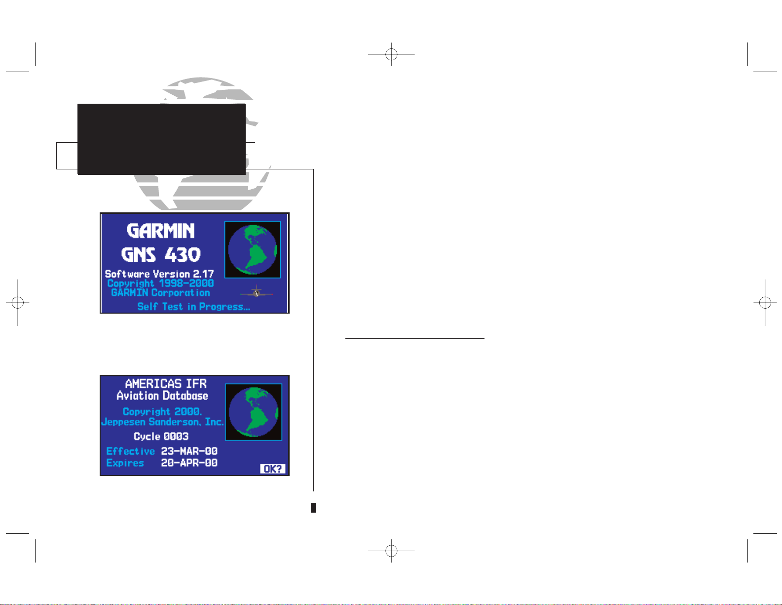
Powering up the GNS 430
The GNS 430’s power and COM volume are controlled using the
k
(power/
volume) knob at the top left corner of the unit. Rotating it clockwise will turn unit
power on and increase the COM radio volume. After turning the unit on, a
welcome page will be displayed while the unit performs a self test, followed by the
the land data page.
The database confirmation page will appear next, which shows the current data-
base information on the NavData card (with the valid operating dates, cycle number and database type indicated). The database is updated every 28 days, and must
be current for approved instrument approach operations. Information on database
subscriptions is available inside your GNS 430 package.
To acknowledge the database information, press the Ekey.
4
The database confirmation page shows the
effective and expiration dates of the Jeppesen
database on the NavData Card.
The welcome page appears when the GNS
430 is turned on. During the time this screen
is displayed, the GNS 430 performs a self-test
to ensure proper operation.
430MANF.qxd 7/24/00 4:43 PM Page 4
TAKEOFF TOUR
Instrument Panel
Self-Test
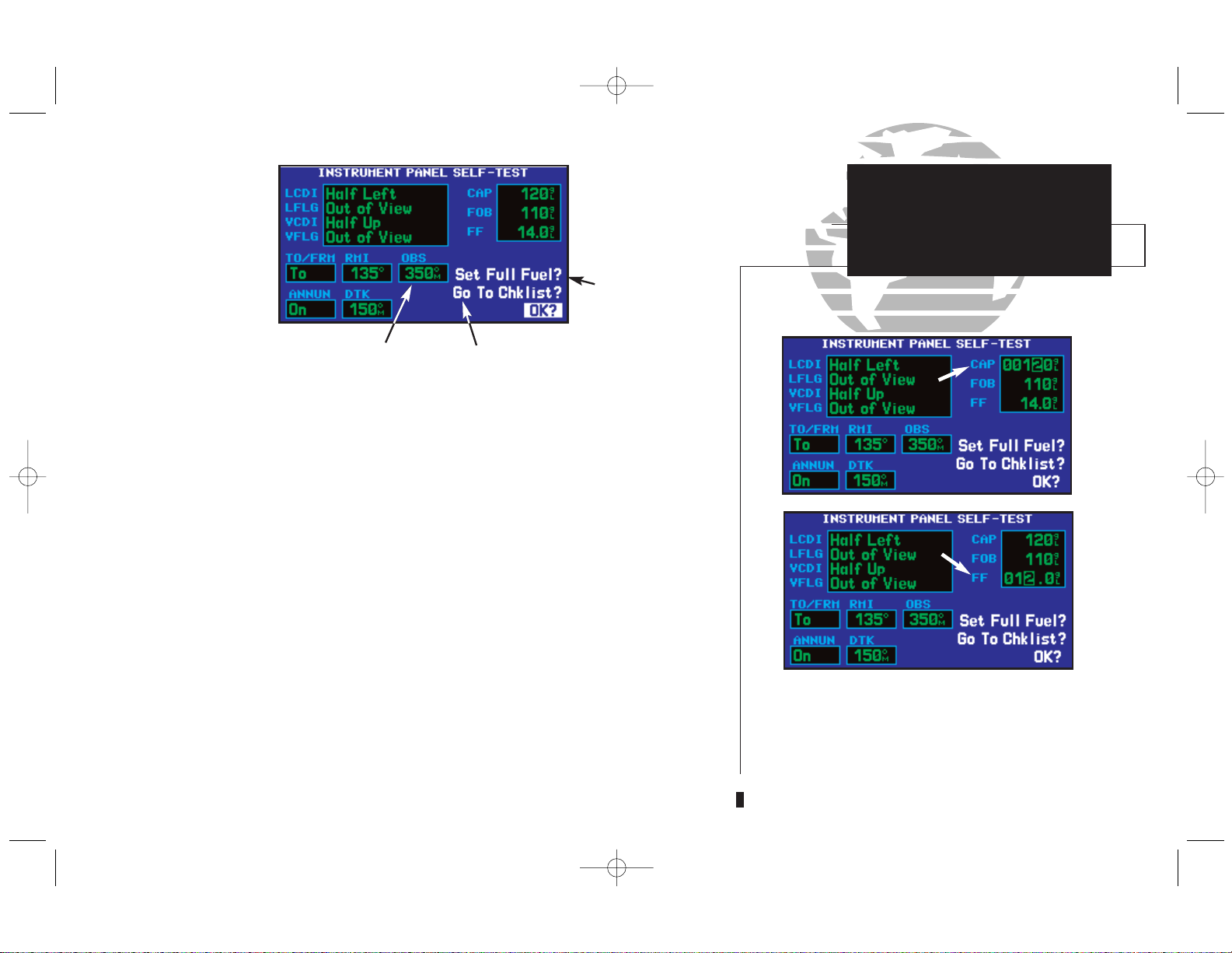
Once the database has been acknowledged, the instrument panel self-test page will
appear. To ensure that your GNS 430 and any connected instruments are working
properly, check for the following indications on your CDI/HSI , RMI, external annunciators and other connected instruments:
• Course deviation - half left / no flag • Glideslope - half up / no flag
• TO/FROM flag - TO • Time to destination - 4 minutes
• Bearing to destination - 135° • Desired track - 149.5°
• Distance to dest. - 10.0 nautical mi. • Ground speed - 150 knots
• All external annunciators (if installed) - on
The instrument panel self-test page indicates the currently selected OBS course,
fuel capacity (CAP), fuel on board (FOB) and fuel flow (FF). The fuel capacity, fuel on
board and fuel flow may be manually entered if your installation does not include connection to sensors which automatically provide these figures.
To enter fuel capacity, fuel on board or fuel flow figures (if not provided by sensors):
1. Rotate the large right knob (d) to select the CAP, FOB or FF field.
2. Rotate the small (
a
) and large (d) right knobs to enter the desired figure, then
press
E
.
5
Fuel Figures: May be
entered manually if
no sensor present
Select to display
Checklists Page
Check CDI/HSI,
RMI and other
instruments
to verify these
indications
Should match current OBS
course selection
Select to Set Fuel
Level to Full Capacity
{
}
Enter the fuel capacity, fuel on board or fuel
flow figures directly onto the appropriate field
of the instrument panel self-test page. These
figures will automatically be provided if your
installation includes connection to external
sensors.
430MANF.qxd 7/24/00 4:43 PM Page 5
The instrument panel self-test page includes selections to set fuel on board
(FOB) to full capacity and access the checklists page. This allows you to quickly set
fuel to full limits and display any checklists you’ve entered, such as start up or takeoff checklists.
To set fuel on board to full (if not provided by sensor):
1. Rotate the large right knob (d) to highlight Set Full Fuel?.
2. Press
E
and verify that fuel on board (FOB) now matches the fuel capacity (CAP)
figure. Fuel on board will now be reduced, over time, based on the fuel flow (FF) figure.
To view the checklists page:
1. Rotate the large right knob (d) to highlight Go To Chklist? and press E.
2. Rotate the large (
d
) right knob to select the desired checklist, then follow the steps on
page 147 to execute each step in the selected checklist.
3. Once you complete the desired checklist(s), press the small right knob (
v
) to return to
the checklists page. Press the small right knob (
v
) again to return to normal operation
on the satellite status or map pages.
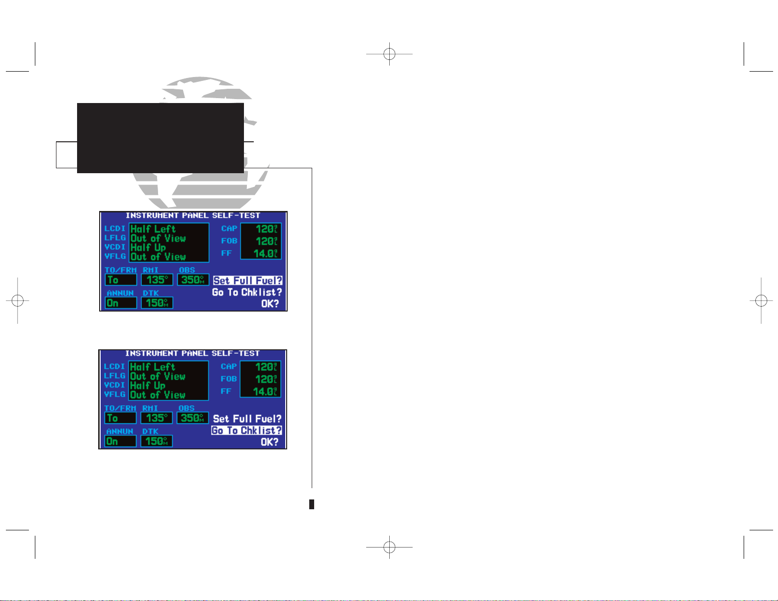
Once you’ve verified instrument operation with the instrument panel self-test
page displayed, press the
E
key.
The satellite status page will appear as the GNS 430 begins to collect satellite
information. An ‘Acquiring’ status will be displayed on the satellite status page, and
the signal strength of any satellites received will appear as “bar graph” readings.
This is a good indication that you are receiving signals and a position fix will be
determined. Following the first-time use of your GNS 430, the time required for a
position fix will vary—usually from one to two minutes.
6
Select “Set Full Fuel?” to set fuel on board
(FOB) to full capacity.
Select “Go To Chklist?” to display the checklist page and any available checklists. The
GNS 430 can hold up to nine checklists with
up to 30 entries in each checklist.
TAKEOFF TOUR
Fuel On Board
and Checklists
430MANF.qxd 7/24/00 4:43 PM Page 6
If the unit can only obtain enough satellites for 2D navigation (no altitude), the
unit will use the altitude provided by your altitude encoder (if one is connected).
If the GNS 430 has not been operated for a period of six months or more, it may
have to ‘Search the Sky’ to collect new data. This means the unit is acquiring satellite data to establish almanac and satellite orbit information, which can take 5 to 10
minutes. The satellite status page will display a ‘Search Sky’ status, and the
message annunciator (MSG), above the
M
key, will also flash to alert you of a
system message, ‘Searching the Sky’.
To view a system message, press
M
.
The message page will appear and display the status or warning information
applicable to the receiver’s current operating condition.
To return to the previous page after viewing a message, press
M
again.
7
The satellite status page shows the ID numbers for the satellites and the relative signal
strength of each satellite received (as a “bar
graph” reading.
‘Search Sky’ indicates that satellite almanac
data is not available or has expired (if the
unit hasn’t been used for six months or more).
The data will be recollected from the first
available satellite.
The ‘INTEG’ annunciator (bottom left corner
of the screen) indicates that satellite coverage
is insufficient to pass built-in integrity monitoring tests. In the example above, not enough
satellites are being received to determine a
position.
Message Page
TAKEOFF TOUR
Acquiring Satellites &
Viewing Messages
430MANF.qxd 7/24/00 4:43 PM Page 7
PROCEDURES
Approach Examples
5
TAKEOFF TOUR
Selecting COM and
VLOC Frequencies
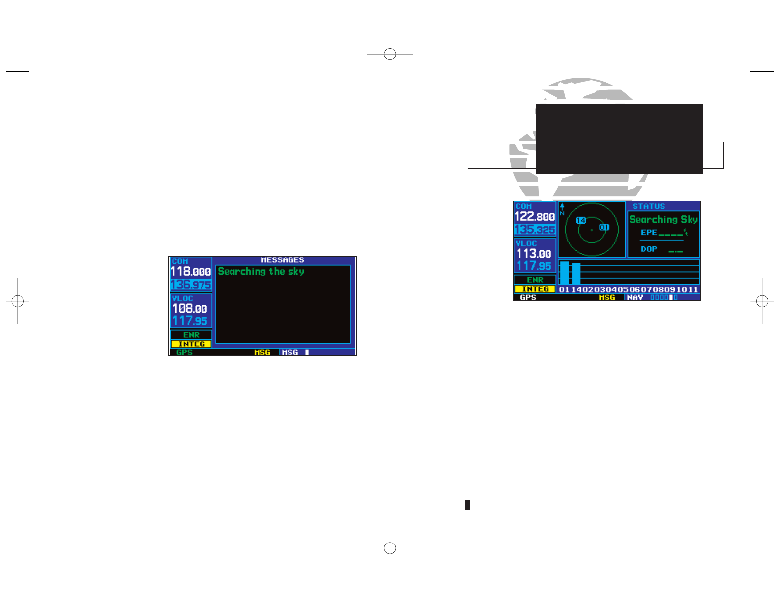
While the GNS 430 is acquiring a position, let’s take a minute to dial in the
active and standby frequencies you’ll be using for the first phase of your flight. The
GNS 430’s display is divided into separate ‘windows’ (or screen areas), including a
COM window, VLOC window and the GPS window (the right 3/4 of the display).
Pushing the small left knob (
v
) activates the tuning cursor in the desired fre-
quency window. To select the active frequency, you must first enter the frequency in
the standby field, and use the W(or V) key to move it to the active field.
To change the standby communication frequency:
1. Press the small left knob (v) if needed, to move the tuning cursor to the COM window.
2. Rotate the large left knob (
h
) to select the MHz, and the small left knob (f) to select
the kHz of the desired frequency.
To place the standby communication frequency in the active field, press W.
Once you’ve entered the active frequency, simply repeat steps 1 and 2, above, to
enter the standby frequency. After both communication frequencies have been
entered, you may elect to keep the COM window ‘hot’ by leaving the cursor on the
standby frequency, or move the cursor to the VLOC window by pressing the small
left knob (
v
). NOTE: When selecting VLOC frequencies, the tuning cursor will
automatically return to the COM window after 30 seconds of inactivity.
8
COM Window
GPS Window
Active Frequency on top &
Standby on bottom
(highlighted by cursor)
{
{
VLOC Window
Satellite status page with cursor active in
COM window.
To switch the active and standby frequencies,
press the
W
key. Switching the active and
standby frequencies will not remove the cursor from the COM window.
}
430MANF.qxd 7/24/00 4:43 PM Page 8
TAKEOFF TOUR
Map Page
The map page combines a moving map display
and navigation data for complete situational
awareness. Map setup pages are provided to
designate the maximum scale at which each
map feature will appear. These settings provide an automatic decluttering of the map
(based upon your preferences) as you adjust
the scale.
While viewing the map page, you can quickly
declutter and remove many of the background
map details by pressing the
c
key (repeat-
edly) until the desired detail is depicted.
To change the map scale, press the
P
or
#
side of the
R
key.
To change the standby VLOC frequency:
1. Press the small left knob (v), if needed, to activate the tuning cursor in the VLOC
window.
2. Rotate the large left knob (
h
) to select the MHz, and the small left knob (a) to select
the kHz of the desired frequency.
To place the standby frequency in the active field, press V.
After the GNS 430 acquires satellites and computes a position, the map page
will appear automatically.
The map page displays your present position (using an airplane symbol) relative
to nearby airports, VORs, NDBs, intersections, user waypoints and airspace boundaries—and your route displayed as a solid line. Data fields for destination waypoint
(WPT), distance to waypoint (DIS), desired track (DTK) and ground speed (GS)
appear on the right hand side of the display. These fields are user selectable (see
page 37 for more information) to allow you to configure the unit to your own preferences. Available settings include: altitude, bearing, enroute safe altitude, estimated
time of arrival, minimum safe altitude, and ground track. See Section 10 for definitions of these navigation terms.
9
Data
Fields
Present
Position
Map Display
Map Scale
Map Page
Desired Track
430MANF.qxd 7/24/00 4:43 PM Page 9
PROCEDURES
Approach Examples
5
The map page is one of six pages available under the NAV group*:
• Default NAV page • Map page
• NAVCOM page • Position page
• Satellite status page • Vertical navigation page
To select the desired NAV page, rotate the small right knob ( a) until the desired
page is displayed.
If you are currently viewing a page which is not part of the NAV group, you can
quickly return to the NAV group using the ckey.
To select the NAV group and display the default NAV page, press and hold c.
MAIN PAGE GROUPS
In addition to the NAV group of pages, additional groups of pages are available for
waypoint information (WPT), auxiliary (AUX) functions such as flight planning or unit
settings, and listings for nearest (NRST) airports or other facilities.
To select the desired page group, rotate the large right knob (d) until a page from
the desired group is displayed.
To select the desired page within the group, rotate the small right knob (
a
) until
the desired page is displayed.
8 available
pages (see
list on pg. 16)
6 available
pages* (see
list above)
The bottom right corner of the screen indicates which page group is currently being displayed (e.g., NAV or NRST), the number of
screens available within that group (indicated
by square icons) and the placement of the current screen within that group (indicated by a
highlighted square icon). To select a different
page within the group, rotate the small right
knob (
a
).
* Seven NAV Pages are available when the
GNS 430 installation includes connection to
traffic and/or weather information sources.
See 400 Series Pilot’s Guide Addendum, part
number 190-00140-10.
TAKEOFF TOUR
NAV Pages &
Page Groups
10
NAV
NRST
10 available
pages (see
list on pg. 94)
4 available
pages (see list
on pg. 131)
AUXWPT
430MANF.qxd 7/24/00 4:43 PM Page 10
TAKEOFF TOUR
Page Groups
11
d
(Large right knob to change page groups)
(Small right knob to select pages within the group)
a
Default NAV
Map
NAVCOM
Position
Satellite Status
VNAV
Airport Location
Airport Runway
Airport Frequency
Airport Approach
Airport Arrival
Airport Departure
Intersection
NDB
VOR
User Waypoint
Flight Planning
Utility
Setup 1
Setup 2
Nearest Airport
Nearest Intersection
Nearest NDB
Nearest VOR Nearest User Waypoint
Nearest Center
Nearest Flight Service
Nearest Airspace
NAV Group
WPT Group
AUX Group
NRST Group
Selection of any main page is performed using the large (d) and small (a) right knobs. The large right knob (d) selects the page group: NAV, WPT,
AUX or NRST. The small right knob (
a
) selects the desired page within a group. To quickly select the default NAV page, press and hold c.
430MANF.qxd 7/24/00 4:43 PM Page 11
PROCEDURES
Approach Examples
5
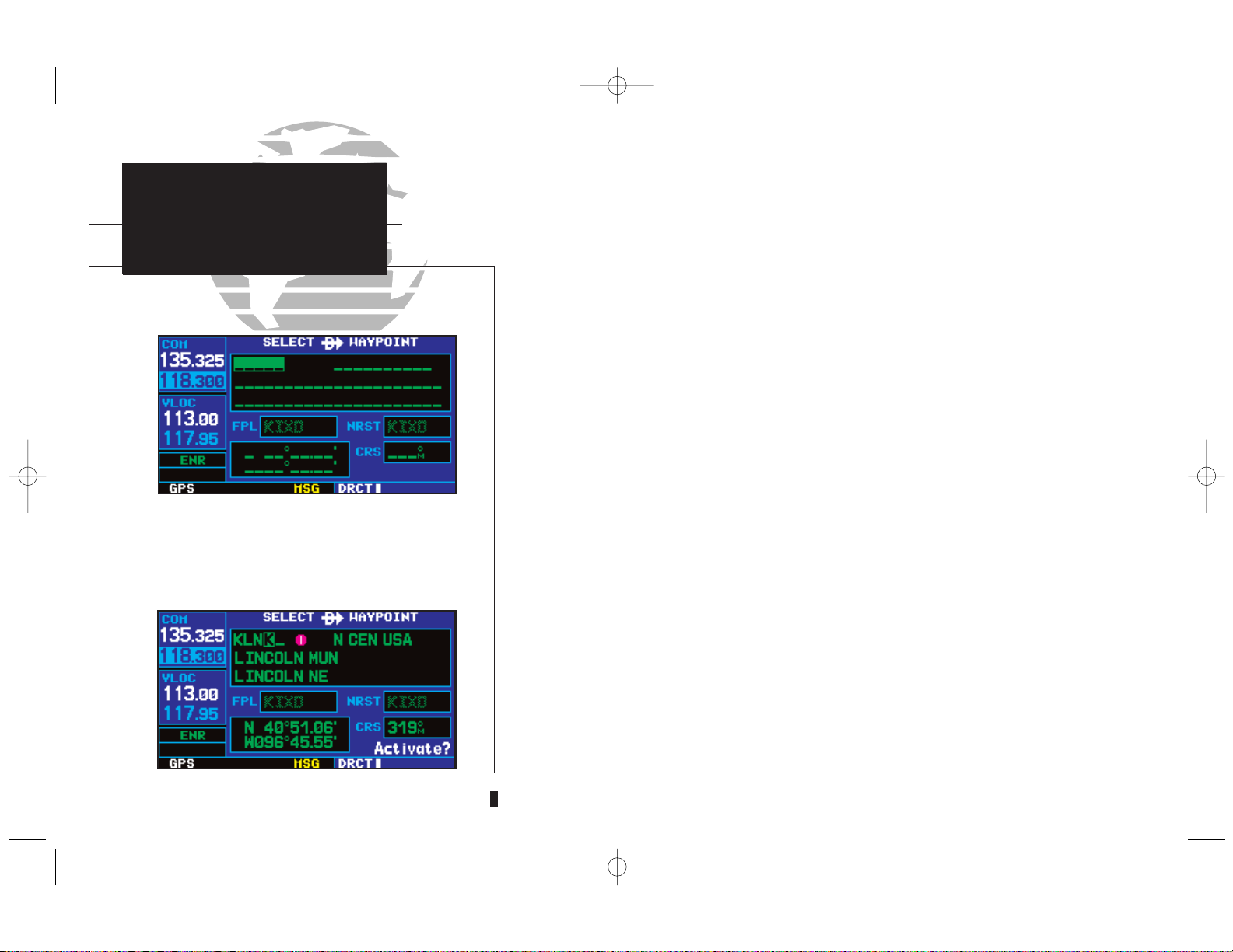
The GNS 430 can use direct point-to-point navigation to guide you from takeoff
to touchdown, even in the IFR environment. Once a destination is selected, the
unit will provide speed, course and distance data based upon a direct course from
your present position to your destination. A destination can be selected from any
page with the D(direct-to) key.
To select a direct-to destination:
1. Press the Dkey. The select direct-to waypoint page will appear with the destination
field highlighted.
2. Rotate the small right knob (
a
) to enter the first letter of the destination waypoint identifier. The destination waypoint may be an airport, VOR, NDB, intersection or user waypoint, as long as it is in the database or stored in memory as a user waypoint.
3. Rotate the large right knob (
d
) to the right to move the cursor to the next character
position.
4. Repeat steps 2 and 3 to spell out the rest of the waypoint identifier.
5. Press
E
to confirm the identifier. The Activate? function field will be highlighted.
6. Press
E
to activate a direct-to course to the selected destination.
12
Confirm the selected direct-to destination by
highlighting “Activate?” and pressing
E
.
TAKEOFF TOUR
Direct-To Navigation
“Activate?”
Function Field
Select Direct-To Waypoint Page
Destination
Waypoint
Identifier Field
Once a direct-to destination is selected, press
and hold
c
to display the default NAV
page.
430MANF.qxd 7/24/00 4:43 PM Page 12
TAKEOFF TOUR
Default NAV Page
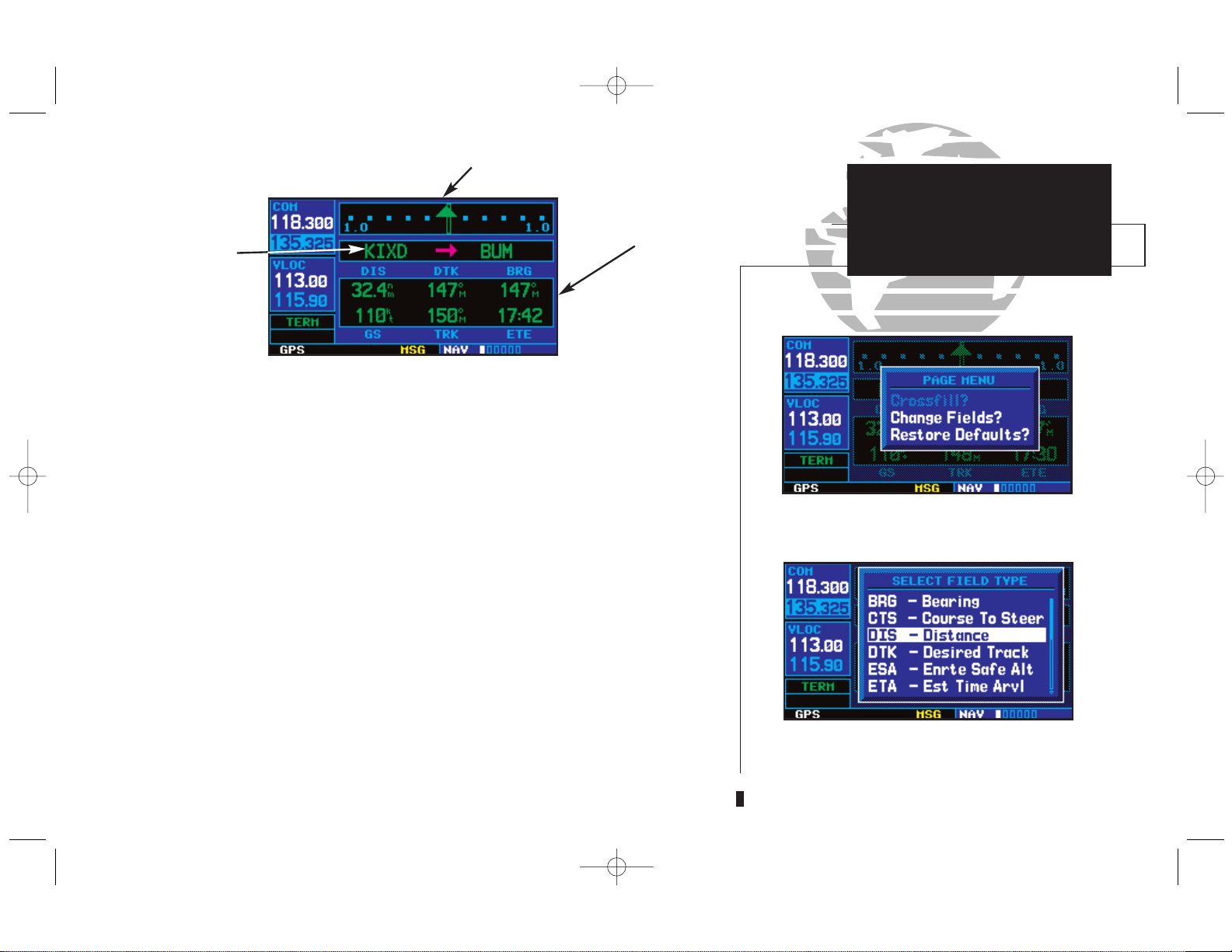
During most flights, the default NAV, map and NAVCOM pages will be the pri-
mary pages used for navigation. The default NAV page displays a graphic course
deviation indicator (CDI), the active leg of your flight plan (as defined by the current “from” and “to” waypoints), and six user-selectable data fields. The default settings for these fields are distance to waypoint (DIS), desired track (DTK), bearing to
waypoint (BRG), ground speed (GS), ground track (TRK) and estimated time en
route (ETE). See Section 10 for definitions of these navigation terms. The default
NAV page is selected using the steps described on page 10.
From the default NAV page, simply rotate the small right knob (
a
) to display the
map page (see page 9) and again to display the NAVCOM page. The NAVCOM page
displays the available frequencies (communications and navigation) for the departure
airport, any en route airports which are included in your flight plan, and the final
destination airport. When using the direct-to function, frequencies will be listed for
the airport nearest to your starting position and the destination airport.
To display the frequency list for the desired flight plan or direct-to airport:
1. Push the small right knob (r) to activate the cursor on the airport identifier field (in the
GPS window).
{continued}
13
Active Leg of
Flight Plan
User-
selectable
Data Fields
Course Deviation Indicator (CDI)
Default NAV Page
The data fields on the default NAV page may
be custom-tailored to your preferences. A menu
selection is provided to “Change Fields?”
The large right knob (
d
) is used to select the
data field you wish to change. Then use the
small right knob (
a
) to display a list of data
options and select the desired data item.
430MANF.qxd 7/24/00 4:43 PM Page 13
PROCEDURES
Approach Examples
5
2. Rotate the small right knob (a) to display the list of airports (departure, arrival and en
route) for your flight plan or direct-to. Continue to rotate the small right knob (
a
) until
the desired airport is selected.
3. Press
E
to display the frequency list for the selected airport.
A frequency listed on the NAVCOM page can be quickly transferred to the
standby field of the COM or VLOC windows. This time saving process prevents
having to “re-key” a frequency already displayed elsewhere on the screen.
To select a communication or navigation frequency:
1. Push the small right knob (r) to activate the cursor in the GPS window.
2. Rotate the large right knob (
d
) to select the desired frequency from the list.
3. Press
E
to transfer the selected frequency to the standby field in the COM or VLOC
window. COM frequencies will automatically go to the standby field of the COM window
and navigation frequencies will automatically go to the standby field of the VLOC window,
regardless of which window is currently highlighted by the cursor.
4. To activate the selected frequency, press the
W
or Vkey.
14
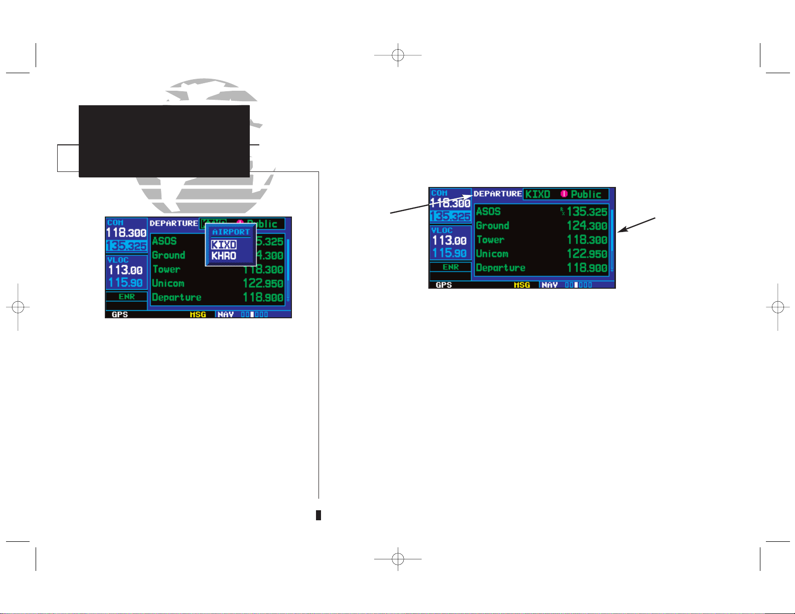
TAKEOFF TOUR
NAVCOM Page
The navigation/communications (NAVCOM)
page provides a complete list of airport frequencies at your departure, en route and
arrival airports. To place a frequency from this
list on standby, highlight the desired frequency and press
E
.
To display frequencies for a different airport
along your flight plan, press the small right
knob
(r)
to highlight the airport identifier
field. Rotate the small right knob (
a
) to display the list of airports within your flight plan.
Continue rotating the small right knob (
a
) to
select the desired airport and press
E
.
Arrival,
Enroute or
Departure Airport
Frequency
List
NAVCOM Page
430MANF.qxd 7/24/00 4:43 PM Page 14
TAKEOFF TOUR
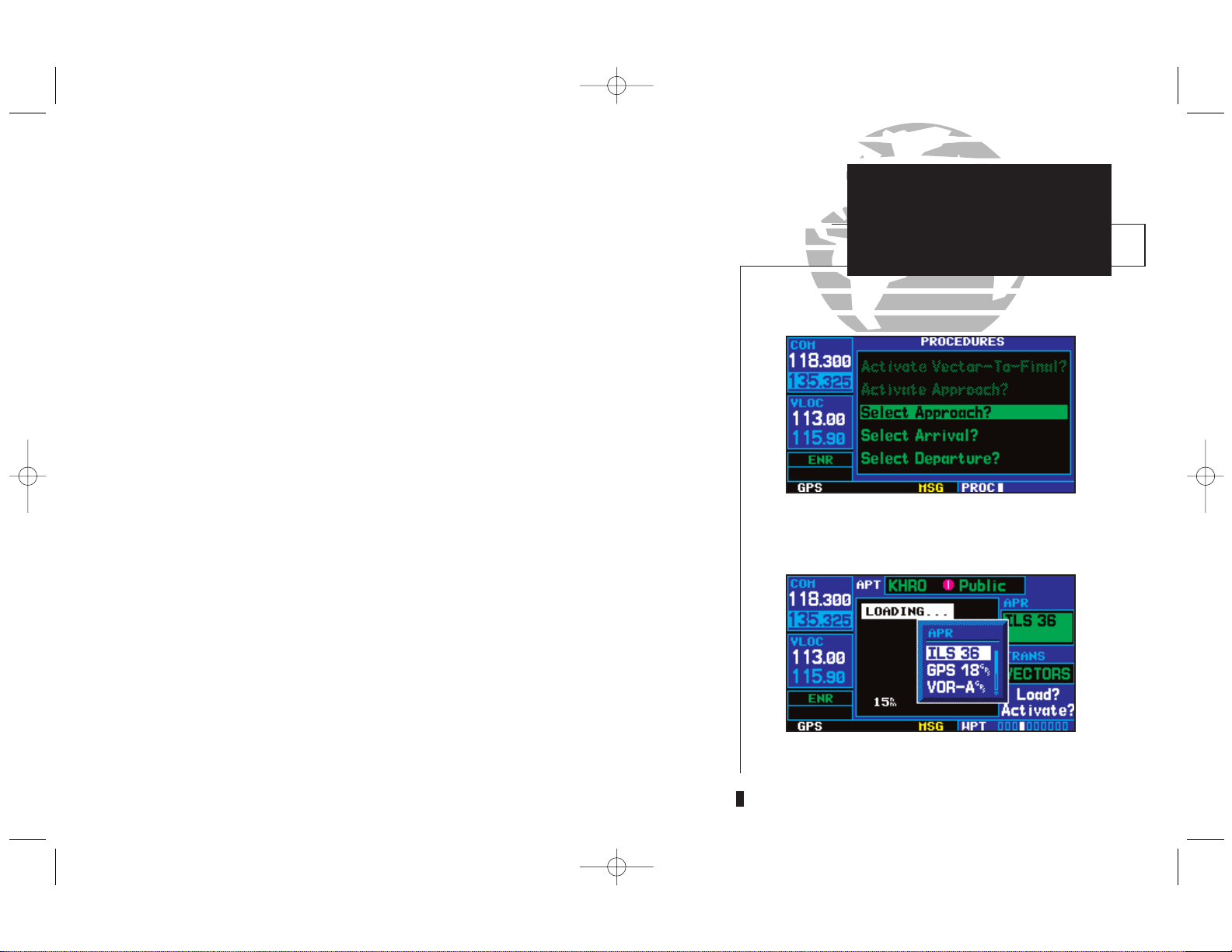
IFR Procedures
Once the direct-to or flight plan is confirmed, the whole range of instrument
procedures is available to you. Departures (SIDs), arrivals (STARs), non-precision
and precision approaches are stored within the NavData card and available using
the
P
(procedures) key.
To display the procedures page, press
P
.
The steps required to select and activate an approach, departure or arrival are
identical. In this introductory section, we’ll show examples of the steps required to
select an approach, but keep in mind the same process also applies to departures
and arrivals.
To select an approach, departure or arrival:
1. Rotate the small right knob (a) to select the desired option (Select Approach?,
Select Arrival? or Select Departure?) from the procedures page.
2. Press
E
to display a list of available procedures for the arrival (when using
approaches or STARs) or departure (when using SIDs) airport.
3. Rotate the small right knob (
a
) to select the desired procedure and press E.
4. For approaches, a window appears to select the desired initial approach fix (IAF) or provide a vectors option to select just the final course segment of the approach. Rotate the
small right knob (
a
) to select the desired option and press E. (The vectors option
extends the final inbound course beyond the final approach fix, allowing you to intercept
the final course segment beyond its normal limits.)
5. For departures and arrivals, a window appears to select the desired transition. Rotate the
small right knob (
a
) to select the desired option and press E.
In your flight plan or direct-to, the departure or arrival airport is replaced with
the sequence of waypoints contained within the selected procedure.
15
Press the
P
key to display the procedures
page. Rotate the large right knob (
d
) to
select the desired option.
A window will appear to select the desired
procedure. Use the large right knob (
d
) to
make your selection.
430MANF.qxd 7/24/00 4:43 PM Page 15
PROCEDURES
Approach Examples
5
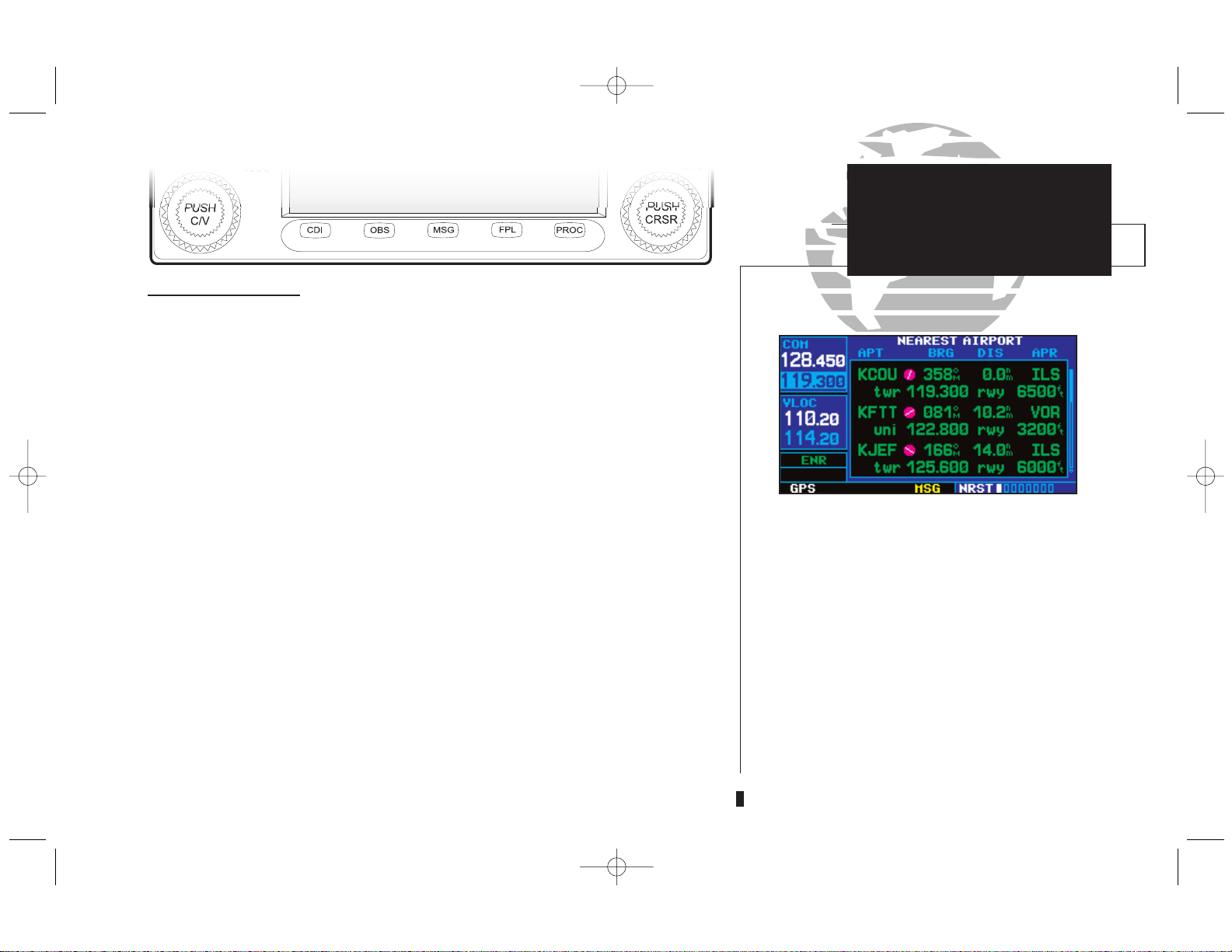
From page 10 you may recall that one of the main page groups, NRST, provides
listings for nearest airports or other facilities. The NRST group provides detailed
information on the nine nearest airports, VORs, NDBs, intersections and user-created waypoints within 200 nautical miles of your current position. In addition,
pages are also provided to display the five nearest center (ARTCC/FIR) and Flight
Service Station (FSS) points of communication, plus alert you to any special-use or
controlled airspace you may be in or near.
To display the NRST pages:
1.
If necessary, press the small right knob
(r) to remove the cursor from the page.
2. Rotate the large right knob (
d
) to select the NRST page group, as indicated by NRST
appearing in the lower right corner of the screen (see page 10).
3. Rotate the small right knob (
a
) to select the desired NRST page.
The nearest airport page (shown at left) is one of eight pages available under the
NRST group:
• Nearest airport page • Nearest intersection page
• Nearest NDB page • Nearest VOR page
• Nearest user waypoints page • Nearest ARTCC page
• Nearest FSS page • Nearest airspace page
You may examine both the communication frequencies and runway information
directly from the nearest airport page. As discussed earlier for the NAVCOM page
(see page 14), you may also place any displayed frequency into the standby COM or
VLOC field by highlighting the frequency with the cursor and pressing
E
.
16
TAKEOFF TOUR
Nearest Airport
Emergency Search
To display a list of nearby airports, rotate the
large right knob (
d
) to select the NRST page
group and (if needed) the small right knob
(
a
) to select the nearest airport page.
To scroll through the list, press the small right
knob (
a
), then rotate the large right knob
(
d
).
430MANF.qxd 7/24/00 4:43 PM Page 16

TAKEOFF TOUR
Nearest Airports: Additional
Information and Direct-to
To view additional information for a nearby airport:
1. Press the small right knob (r) to activate the cursor.
2. Rotate the large right knob (
d
) to select the desired airport from the list.
3. Press
E
to display waypoint (WPT) information pages for the selected airport.
4. To display runway and frequency information, press (
r
) to remove the cursor and
rotate the small right knob (
a
) to display the desired information page.
The nearest airport page may be used in conjunction with the direct-to (D)
key to quickly set a course to a nearby facility in an in-flight emergency. Selecting a
nearby airport as a direct-to destination will override your flight plan or cancel a
previously selected direct-to destination. (You’ll still have the option of returning to
your flight plan by cancelling the direct-to. See page 53.)
To select a nearby airport as a direct-to destination:
From the nearest airport page...
1. Press the small right knob (
r
) to activate the cursor.
2. Rotate the large right knob (
d
) to select the desired airport from the list.
3. Press
D, E
and E(again) to navigate to the nearby airport.
From an airport information page...
1. Press
D, E
and E(again) to navigate to the nearby airport.
17
Additional information for a nearby airport is
available by highlighting an identifier on the
list and pressing
E
.
To select a nearby airport as a new destination, highlight its identifier, press
D, E
and
E
(again).
430MANF.qxd 7/24/00 4:43 PM Page 17
PROCEDURES
Approach Examples
5
The last page in the NRST group, the nearest airspace page, provides informa-
tion for up to nine controlled or special-use airspaces near or in your flight path.
Airspace information appears on this page based upon the same criteria used for airspace alert messages. Nearby airspace information and airspace alert messages are
provided according to the following conditions:
• If your projected course will take you inside an airspace within the
next ten minutes, the message “Airspace ahead -- less than 10
minutes” will appear.
• If you are within two nautical miles of an airspace and your current
course will take you inside, the message “Airspace near and ahead”
will appear.
• If you are within two nautical miles of an airspace and your current
course will not take you inside, the message “Near airspace less than
2nm” will appear.
• If you have entered an airspace, the message “Inside Airspace” will
appear.
By default, airspace alert messages are turned off. When turned on, the message
(MSG) annunciator located directly above the
M
key will flash to alert you to the
airspace message. (See page 154 for information on enabling airspace alert messages.)
To view an airspace alert message:
1. Press the
M
key. The message page appears with the alert message.
2. Press
M
again to return to the previous display.
Note that the airspace alerts are based upon three-dimensional data (latitude,
longitude and altitude) to avoid nuisance alerts. The alert boundaries for controlled
airspace are also sectorized to provide complete information on any nearby airspace.
Additional information about a nearby airspace—such as controlling agency, frequency and floor/ceiling limits—is available from the nearest airspace page (see
page 128 and illustrations shown at left).
18
TAKEOFF TOUR
Special-use and
Controlled Airspace
When an airspace alert occurs, the message
(MSG) annunciator will flash. Press
M
to
view the alert message.
To view additional information about the airspace, select the nearest airspace page.
Detailed information is available by highlighting the airspace name and pressing
E
.
430MANF.qxd 7/24/00 4:43 PM Page 18
TAKEOFF TOUR
Flight Plans
The GNS 430 lets you create up to 20 flight plans, with up to thirty-one way-
points in each flight plan. Flight plans are created, edited and activated using the
F
key. The FPL page group includes two pages: the active flight plan page and
the flight plan catalog. The active flight plan page provides information and editing
features for the flight plan currently in use (referred to as “flight plan 00”). The
flight plan catalog serves as the main page for creating new flight plans, as well as
editing or activating previously created flight plans.
Since using flight plans is arguably one of the more complex features of the GNS
430, we’ll only discuss it briefly here — focusing on creating a new flight plan and
activating it to use for navigation. After reading through this brief introduction,
answers to additional questions you may have about flight plans can be found in the
reference section, starting on page 54.
To create a new flight plan:
1.
Press the
F
key and rotate the small right knob
(a)
to select the flight plan catalog.
2. Press the mkey to display the flight plan catalog options.
3. Rotate the large right knob (
d
) to select Create New Flight Plan? and press E.
4. The cursor will appear on the first waypoint identifier field (located directly below WAYPOINT). Use the large (
d
) and small (a) right knobs to enter the identifier of the first
waypoint in the flight plan. (The small knob is used to select the desired letter or number
and the large knob is used to move to the next character space.)
5. Press
E
once the identifier has been selected. The cursor will move to the next
blank waypoint identifier field.
6. Repeat steps 4 and 5, above, until all waypoints for the flight plan have been entered.
19
Active flight plan page with flight plan
currently in use.
To create a new flight plan, select “Create
New Flight Plan?” from the flight plan catalog
options.
430MANF.qxd 7/24/00 4:43 PM Page 19
PROCEDURES
Approach Examples
5
Once the flight plan is created, it may be activated from an options window.
Activating the flight plan will place it into “flight plan 00” (a copy of it will still
reside in the original catalog location) and replaces any flight plan which currently
exists in “flight plan 00.”
To activate the new flight plan:
1. Press the mkey to display the flight plan catalog options.
2. Rotate the small right knob (a) to select Activate Flight Plan? and press E.
This Takeoff Tour is intended to provide a brief introduction of the GNS 430’s
major features. The Reference section of this manual describes these features, and
others, in additional detail. Use the Reference section, as needed, to learn or review
the details regarding a particular feature. The Index (beginning on page 187) may
be used to quickly locate the information you want within the reference section.
Now that you’re familiar with the basics, some suggested reading within the
Reference section includes:
• Flight plan features - see page 54
• Waypoint information pages (database information) - see page 94
• IFR procedures - see page 66
• Unit settings (configuring the unit to your preferences) - see page 135
If you’re unable to locate the information you need, we’re here to help!
GARMIN’s Customer Service staff is available during normal business hours (U.S.
Central time zone) at the phone and fax numbers listed on page iv. You can also
reach us by mail (see page iv) or at our web site address: www.garmin.com.
20
TAKEOFF TOUR
Flight Plans and
Additional Reading
Enter the identifier for each airport and/or
navaid into the flight plan in the same
sequence you wish to fly.
Select “Activate Flight Plan?” from the page
menu to begin using the new flight plan.
430MANF.qxd 7/24/00 4:43 PM Page 20
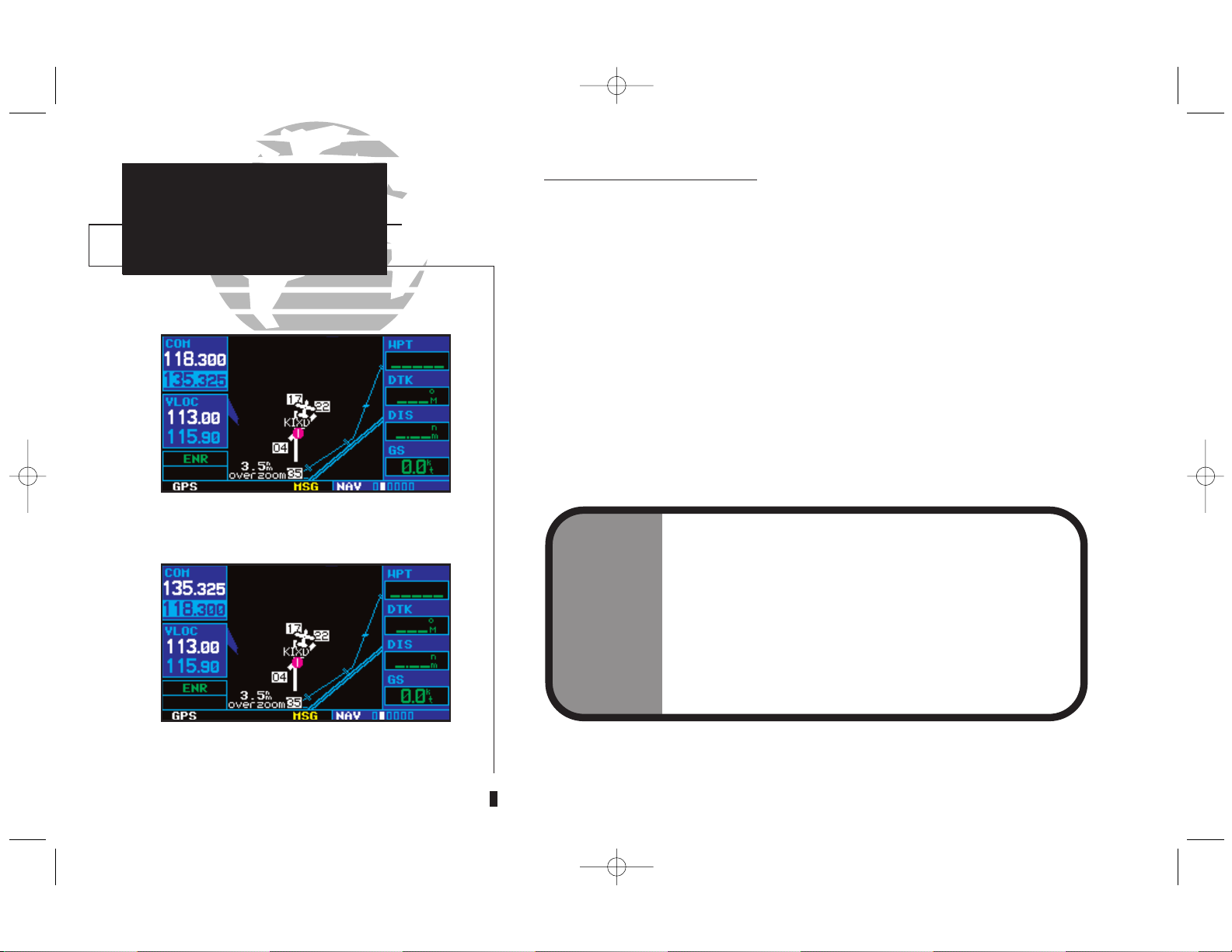
COM
Radio Volume
Auto Squelch
Section 1
Communicating with the GNS 430
The GNS 430 features a digitally-tuned VHF COM radio that provides a seamless transition from communication to navigation, bringing the two most important
functions in flying together in one panel-mounted unit. The GNS 430’s COM radio
operates in the aviation voice band, from 118.000 to 136.975 MHz, in 25 kHz steps
(default). For European operations, a COM radio configuration to allow for 8.33
kHz steps is also provided (see pages 160-161).
Volume
COM radio volume is adjusted using the kknob. Rotate the kknob clockwise to increase volume, or counterclockwise to decrease volume.
Squelch
The COM radio features an automatic squelch, providing maximum sensitivity
to weaker signals while rejecting many localized noise sources. You may wish to
override this automatic squelch function when listening to a distant station or when
setting the desired volume level. The kknob allows you to disable the automatic
squelch and keep the COM audio open continuously.
To override the automatic squelch, press the kknob momentarily. Press
k
again to return to automatic squelch operation.
21
Press the kknob momentarily to override
the automatic squelch. Note the “RX” receive
indication when receiving a station.
“TX” appears at the upper right corner of the
screen while transmitting.
1
430MANF.qxd 7/24/00 4:43 PM Page 21
PROCEDURES
Approach Examples
5
COM Window and Tuning
Communication frequencies are selected with the tuning cursor in the standby
COM frequency field, and using the small (
f
) and large (h) left knobs to dial in
the desired frequency. The standby frequency always appears below the active frequency. The active frequency is the frequency currently in use for transmit and
receive operations.
A frequency may also be quickly selected from the database by simply highlight-
ing the desired frequency on any of the main pages and pressing the
E
key. This
process is referred to as auto-tuning. Once a frequency is selected in the standby
field, it may be transferred to the active frequency by pressing the
W
key.
While receiving a station, an “RX” indication appears in the upper right corner
of the COM window — to the immediate right of “COM”. A “TX” indication
appears at this location while you are transmitting.
22
COM
Tuning Cursor
Active/Standby Freqs
Tuning cursor in the COM window. Use the
small (
f
) and large (h) left knobs to dial in
the desired standby frequency.
Once the standby frequency is selected, use
the
W
(flip-flop) key to make the frequency
active for transmit and receive operations.
NOTE
The tuning cursor will normally appear in the COM window, unless placed in the VLOC window by pressing
v
.
When the tuning cursor is in the VLOC window, it will
automatically return to the COM window after 30 seconds
of inactivity.
The active frequency in either window cannot be accessed
directly—only the standby frequency will be highlighted by
the tuning cursor.
1
430MANF.qxd 7/24/00 4:43 PM Page 22
 Loading...