

Page 1

Course Architect 2000
INTRODUCTION
Welcome to EA SPORTS Course Architect™ 2000. For years, this tool has been
used by EA SPORTS™ to design, build, and export golf courses for our golf
games. For the first time, you can use these professional design tools to build the
golf course of your dreams. And, you can import your dream course into Tiger
Woods PGA TOUR® 2000 or Tiger Woods 99 PGA TOUR® Golf to challenge the
pros to a round or tournament on your custom course.
Course Architect 2000 is a 3D development tool that shares features and
methods with 3D graphics programs like 3D Studio Max®. When developing a
course, your base unit is the hole. Each course has eighteen holes that you
configure, load, and design one at a time. When you are working with a course,
you’re presented with a 2D, top-down view of the layout of your course in one
window. Then you can position the 3D camera anywhere in the window, and by
pressing a button, you can render the camera’s view into the 3D View window.
Additional camera modes allow you to watch your design come to life on your PC.
In Locked Cam mode, you can move the 3D camera across the surface of the
course, which automatically updates in the 3D View window from the point of view
of a golfer strolling across the course. In Free Cam mode, you can move the
camera up and down to get the best bird's eye view of your work area. In both
windows, you can use the powerful suite of selection, positioning, and shaping
tools from the desktop. In this manner, you can develop your course from any
vantage point to get the right size, shape, and positioning of its features.
When you have completed your course, a menu item prepares and saves the
course to seamlessly include it in your suite of courses in Tiger Woods 99 PGA
TOUR Golf or Tiger Woods PGA TOUR 2000.
K
EY FEATURES
!
Used for years to build courses for EA SPORTS golf games, this
professional tool has been tuned and updated for easy customer use.
!
Course creation tools fully integrated into one application for WYSIWYG
(What You See Is What You Get) development.
!
Automatic 2D and 3D Views lets you switch in real-time from strategic
planning to detailed implementation.
!
3-plane camera positioning and movement puts the camera right where you
need it.
!
Excellent movement and selection tools give you total command over the
course and its terrain features.
!
Visual tool palettes with keyboard and menu equivalents let you tailor the
controls to your personal preferences.
Page 1
Page 2
Course Architect 2000
!
Get an idea, make the idea: Create holes in any sequence.
!
Build a course, send it to your friends, and play over the net.
!
Game time! One-button course exporter pumps your course from the
Architect directly into the game for easy menu access.
!
Content Library of hundreds of objects, textures, and horizons speed the
development process.
!
Export courses in development to Tiger Woods 99 or Tiger Woods PGA
TOUR 2000 games for test-play. Buid it and test it, and then perfect it to
challenge the TOUR pros.
W
HAT’S NEXT
The remainder of this Introduction describes some of the terms and conventions
of the help guide.
F
OR MORE INFO
www.easports.com.
YSTEM REQUIREMENTS
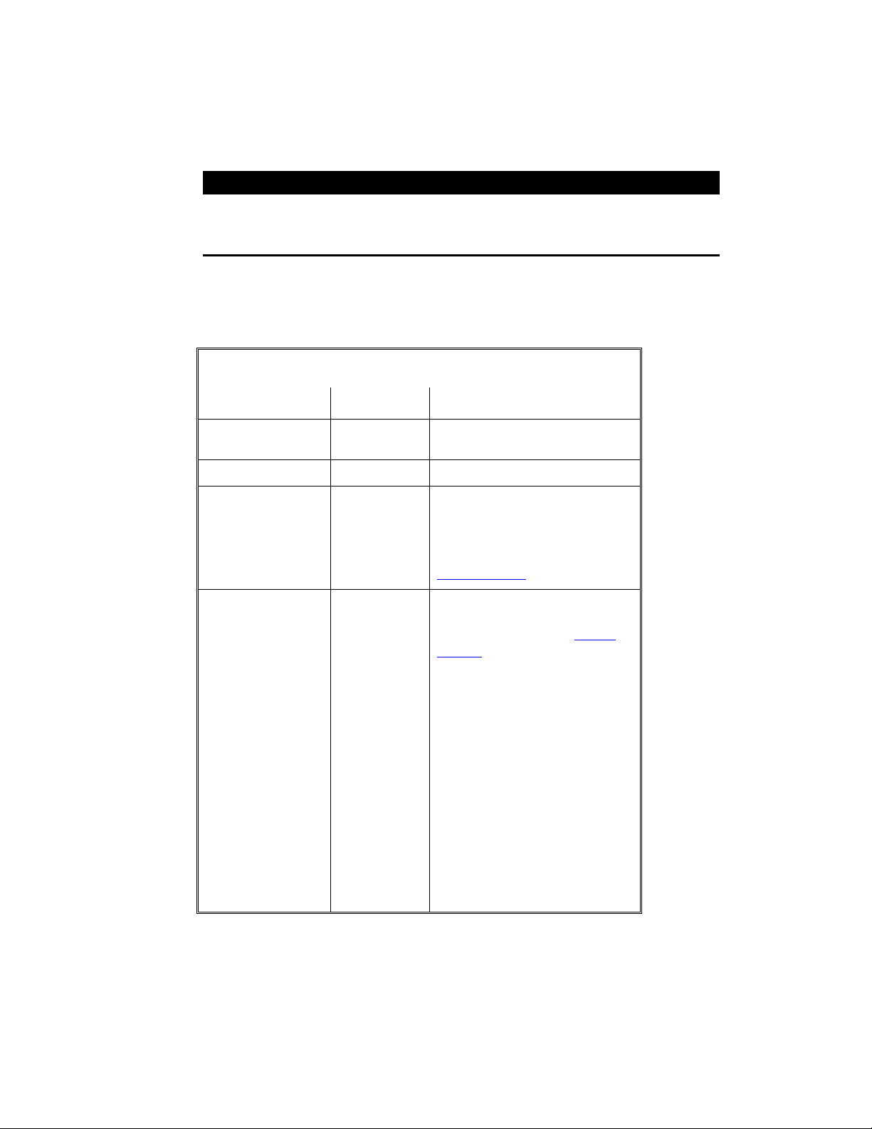
S
M
INIMUM
CPU 200MHz Intel® Pentium®
Operating System Windows® 95/98 (Windows NT not
RAM 64MB
Hard Drive Space 210MB for installation
CD-ROM 4x
?
about this and other titles, check out EA SPORTS on the web at
Processor
supported)
30MB per course
Additional space for Windows swap
file
Display 1MB PCI video card
high-color (16-bit) capable
Other Keyboard, mouse, DirectX 7.0
compatible sound card with
DirectSound™ support
R
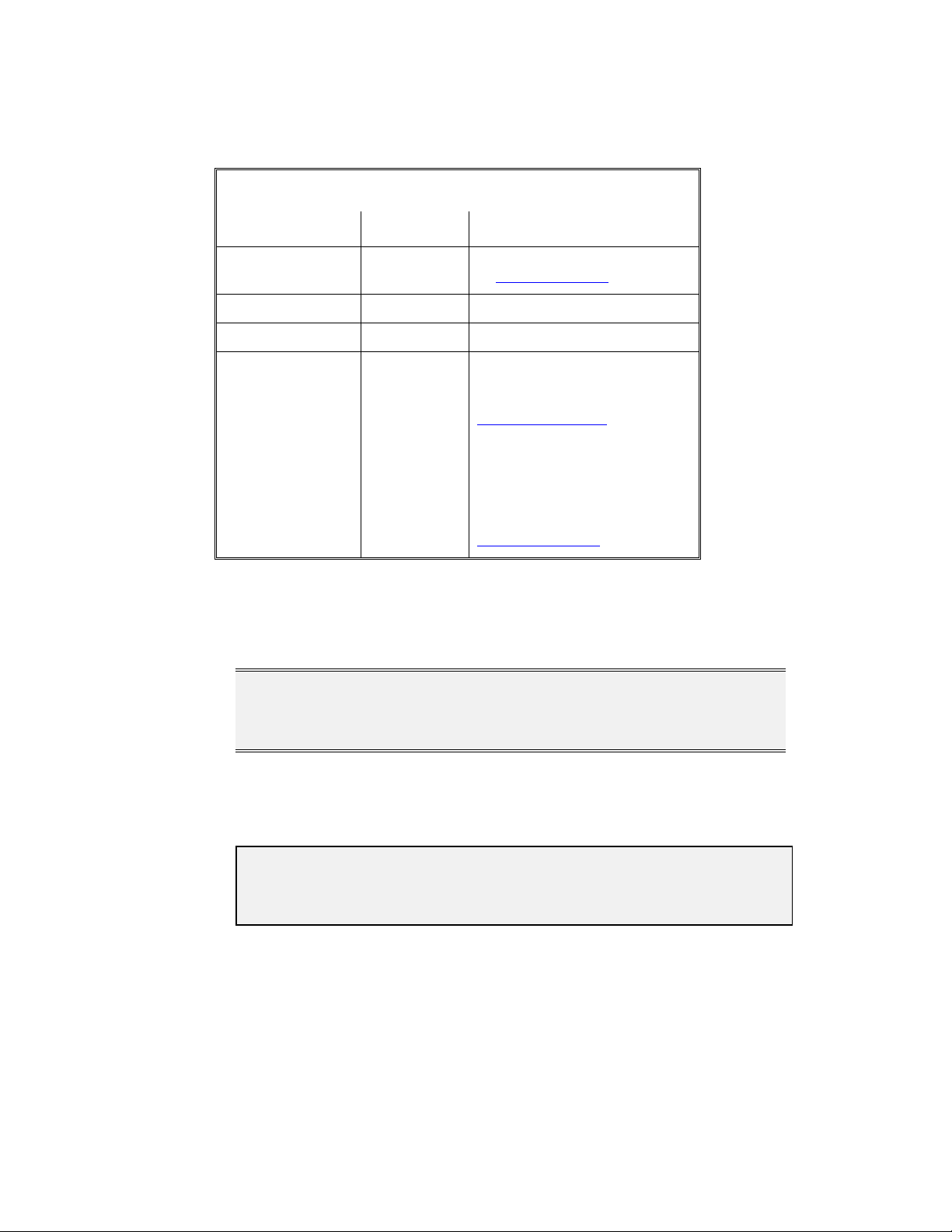
ECOMMENDED
CPU 450MHz Intel Pentium III Processor
RAM 128MB
Hard Drive Space 600MB for installation
30MB per course
Additional space for Windows swap
Page 2
Page 3

Course Architect 2000
file
CD-ROM 4x or faster
32-bit Windows 95/98 CD-ROM
driver
Display 16MB AGP video card
OURSE ARCHITECT CONCEPTS
C
Course Architect 2000 has a number of terms that apply to its special brand of 3D
modeling. While the terms seem easy to understand, they do have special
application inside the tool.
F
ACETS
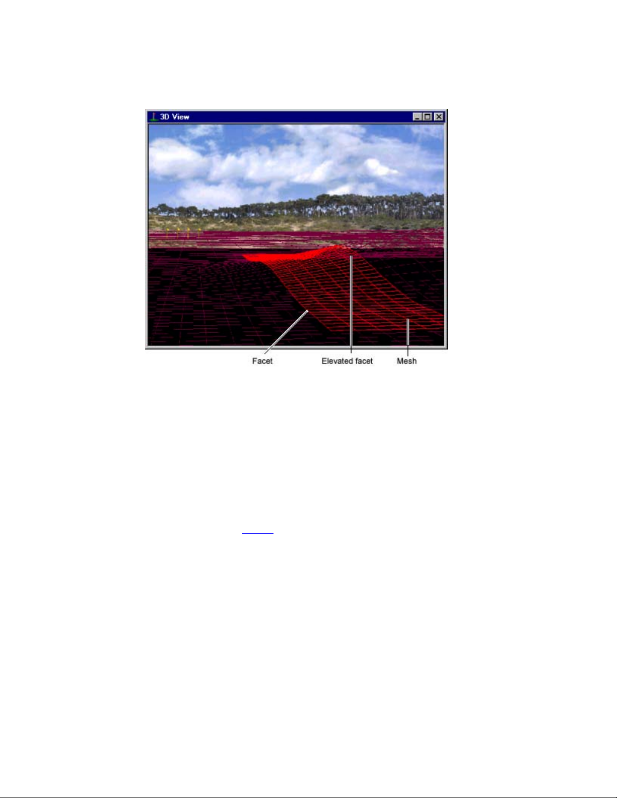
A facet is any four-sided shape. Squares and rectangles
are facets with special characteristics. A facet represents
one square yard in the editor.
The world of computer course design can be described with
facets. By raising and lowering them, the editor can
describe a 3-dimensional surface. If you stretch surface of
the terrain, the side facets stretch to retain the integrity of
the 3-dimensional shape.
When you increase the terrain size of the holes, the
computer adds facets to the environment to give you more
room to build terrain shapes.
H
OLES
In both life and Course Architect 2000, a full golf course is
composed of eighteen holes. In Course Architect 2000, the
hole is the basic unit of development; to build a course, you
build eighteen separate holes.
On your hard drive, each hole is stored inside your course
folder as a separate folder named “Hole01”, “Hole02”, and
so on. The unique files for each hole are stored inside of
this folder. In turn, the hole is saved within a folder bearing
the name of your course.
Page 3
Page 4
Course Architect 2000
M
ESH
Mesh refers to the collection of facets that are linked
together to describe a 3-dimensional shape. By shaping
and placing facets flush against other facets, the computer
defines a seamless mesh that, in total, describes the outer
shell of a 3D shape.
When you manipulate a 3D shape, the computer changes
the shape of the mesh to seal it.
In Course Architect 2000, facets and their mesh are used to
describe the elevation and terrain features of the course.
Facets link together to form a mesh, and the mesh, as a
whole, describes the surface of a hole. For more info on
terrain, !!!! Terrain.
Page 4
Page 5
Course Architect 2000
T
ERRAIN
T
EXTURES
S
HADOWS
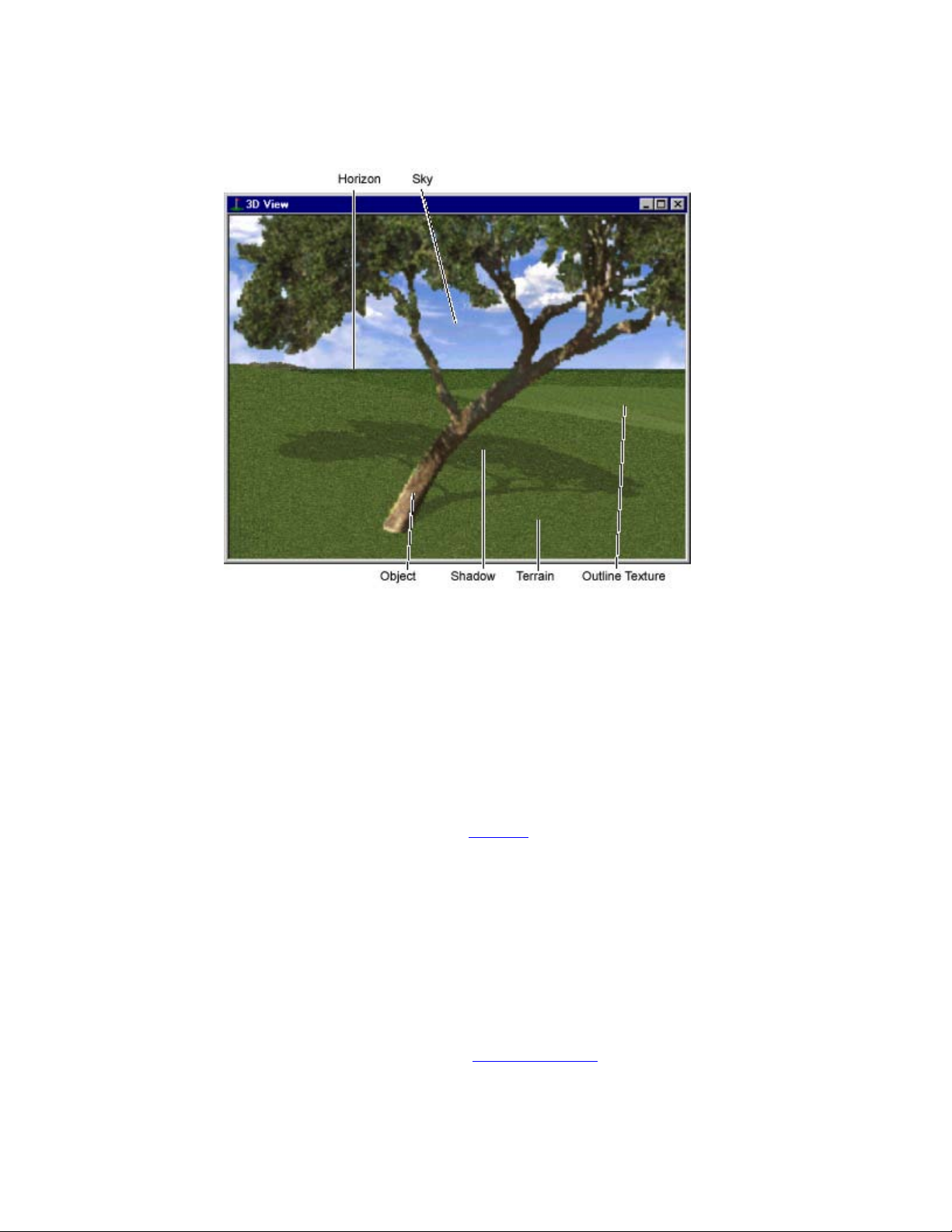
Terrain refers to the 3D mesh of facets that describe the
surface of a hole. With a click and a drag, you can raise
terrain or lower it. You can push, pull, tilt, bump, and
depress terrain. No matter how you manipulate pieces of
terrain in Course Architect 2000, the tool automatically
reshapes the component facets to fill the holes and seams
in it.
You can manipulate terrain pieces of any size and shape.
Course Architect 2000 comes with a large library of textures
that have been specially tailored for use in designing golf
courses. To learn more about how to incorporate textures
into your golf course, ! Textures.
Shadows, we know, are created by the sun. In Course
Architect 2000, the terrain is always outside, so the “sun”
should cause the appearance of shadows. On the
computer, shadows are created by computation. You can
add shadows for interesting and realistic effects. You
position the sun and set some other parameters, and the
tool automatically computes the sun's shadows over objects
like trees, rocks, and other terrain features. You can
position the height and intensity of the sun to simulate timeof-day and climate effects.
For more information, ! Sun and Shadows.
H
ORIZONS
There are several kinds of specialized textures in the tool.
Horizons give the appearance of terrain features in
Page 5
Page 6

Course Architect 2000
photographic detail. Similarly, skies give the appearance of
the sky overhead. The horizons and skies of Course
Architect 2000 have been designed to seamlessly blend
together.
O
UTLINES
To describe the surface of the course, the tool uses a
specialized shape called an outline. An outline is a
malleable 2-dimensional shape that describes the surface
of course features such as greens, tees, sand traps, and
fairways.
Outlines sit on top of the hole’s terrain. To use an outline,
you apply a texture to describe the various kinds of play
surfaces that can appear on a golf course—fairway, green,
tee, sand, and so forth.
With the Outline tools of Course Architect 2000, you can
build outlines of any size and shape. When you reshape the
underlying terrain, the outline automatically stretches to
cover the new terrain features.
P
OINTS
The shape of an outline is described with points. To
manipulate outlines, you use three kinds of points:
boundary, control, and tangent.
Boundary points are eight in number and sit at the corners
and midpoints of the rectangle that surrounds the outline.
To change the overall size of the outline, click and drag the
boundary points.
Control points determine the basic shape of the outline.
You click and drag control points to change the shape of
your outlines.
A pair of tangent points are associated with each control
point. You can use the tangent points to change the
curvature of the outline in the vicinity of the control point.
O
BJECTS
Objects like trees, rocks, and houses can be added to give
authentic flavor and interesting variation to your golf course.
These objects have the appearance and play
characteristics of their real-world counterparts. For more, !
Objects.
ONVENTIONS OF THE TOOL
C
!
Length and width distances are measured in yards, while measurements in
the vertical plane are typically measured in feet.
!
Tab bars group commonly used tools and items. However, you can access
all of the Tab tools through the menu system, and the most common tools
can be selected with hot keys.
!
When an item is selected, you can often open a menu of relevant
commands by clicking the right mouse button. One of the more important
Page 6
Page 7
Course Architect 2000
means of defining a course feature is through its Properties window, which,
if available, can be accessed through the right-click menu.
COURSE ARCHI TECT 2000 D
On a regular basis, Course Architect 2000 team posts upgrades to the tool and
new terrain data files on the EA SPORTS web site. You can download free
software patches plus new textures, terrain maps, objects, horizons and much
more.
F
OR THE LATEST INFORMATION ON COURSE ARCHITECT
http://www.coursearchitect.com
EGINNING COURSE DESIGNERS
B
Beginning designers should read the Introduction and Installation instructions.
After installing Course Architect 2000, read the Overview chapter and follow the
step-by-step tutorial to start your first course hole. After you have completed the
basic tutorial, you can use the rudimentary hole as a reference for further
development and exploration.
DVANCED COURSE DESIGNERS
A
Course Architect 2000 is a graphical tool that allows you both top-down and 3D
views of your work. If you are familiar with tools such as 3D Studio, learning to
use Course Architect 2000 is straightforward. If you are familiar with 3D graphics
tools, you may want to read the rest of the Introduction and then begin digging
into the tool. As you learn, you may find the Quick Start, Reference, and Index
sections helpful.
OWNLOADS
2000:
ONTENTS OF THE
C
When you install Course Architect 2000, you can choose to install the program
with or without the Object Library. This library contains hundreds of images. It
features trees, buildings, rocks, unique textures and more to help build any
course you can imagine.
Tiger Woods PGA TOUR 2000 ships on two CDs. The first CD contains the
game. The second CD contains Course Architect 2000 and its libraries. On
Course Architect 2000 CD, you can access the library inside the \LIBRARY
directory. It includes the following types of objects and materials.
!
Animals
!
Buildings
!
Bushes
!
Cacti
!
Grass
!
Horizons
CD
Page 7
Page 8

Course Architect 2000
!
Rocks
!
Trees
!
Textures
!
Ambient objects (benches, fountains, yardage markers, etc)
ECHNICAL SUPPORT
T
N
EED TECHNICAL SUPPORT
technical support information.
? Please see the enclosed Reference Card for
Page 8
Page 9
Course Architect 2000
QUICK COMMANDS
Use the following Quick Commands to access the most commonly used functions
of Course Architect 2000. The Locked/Free Cam keys let you move the camera in
all directions while you continue to work. The other keys are shortcuts to menu
commands.
L
OCKED/FREE CAM
A
CTION
K
EYS
Move Camera Forward
Move Camera Backward
Move Camera Left
Move Camera Right
Move Camera Up
↑↑↑↑
↓↓↓↓
←←←←
→→→→
[CTRL] + ↑↑↑↑
(Free Cam only)
Move Camera Down
[CTRL] + ↓↓↓↓
(Free Cam only)
F
ILES
A
CTION
K
Open Project [CTRL] + [O]
Save Project [CTRL] + [S]
E
DIT
A
CTION
K
Undo last action [CTRL] + [Z]
Redo last action [CTRL] + [Y]
EYS
EYS
Cut selection [CTRL] + [X]
Copy selection [CTRL] + [C]
Paste selection [CTRL] + [V]
Delete selected object or
[DEL]
outline
Find Objects [CTRL] + [F]
Edit Settings [CTRL] + [ENTER]
C
AMERA
A
CTION
K
EYS
Camera Settings [CTRL] + [ALT] + [C]
Page 9
Page 10
Course Architect 2000
on Terrain Selection
Focus
[CTRL] + [L]
Render Textures [CTRL] + [T]
Render Flat [CTRL] + [B]
Render Wire [CTRL] + [W]
Toggle Display Camera [K]
Display Objects [CTRL] + [J]
Display Outlines [CTRL] + [U]
S
ELECT
A
CTION
K
EYS
Clear All [C]
New [N]
Subtract [S]
Add [A]
Tool Lock [P]
Constrain Texture [X]
Grid [G]
Rectangle [R]
Freehand [F]
Corral []]
Pick Texture [.]
Object [O]
Outline [U]
Grid Size [ALT] + [G]
O
UTLINES
A
CTION
Update Masks [F2]
T
ERRAIN
A
CTION
K
K
EYS
EYS
Mesa [M]
Tilt [T]
Bump [B]
Linear [L]
Page 10
Page 11
Course Architect 2000
Smooth [H]
Flatten [W]
S
HADOWS
A
CTION
K
EYS
Update Terrain Shadows [F3]
Update Object Shadows [F4]
V
IEW
A
CTION
K
EYS
100% [CTRL] + [0] (zero)
Fit [ALT] + [0] (zero)
Grid Display [CTRL] + [G]
2D Grid Settings [ALT] + [CTRL] + [G]
Page 11
Page 12
Course Architect 2000
QUICK START
This Quick Start guide is intended to get you up and working with the Course
Architect 2000 in a short period of time.
N
EED INSTALLATION HELP
installation instructions.
S
OME TERMS
? Please see the enclosed Reference Card for
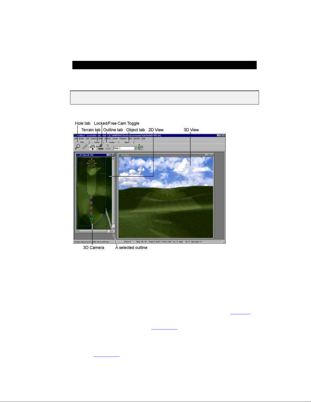
The desktop of Course Architect 2000 supports two different views on your golf
course: 2D and 3D. A 2D View window gives you a top-down perspective on the
hole under construction. You can position the camera icon inside the 2D View to
move the 3D View of the hole in a second window. The Locked/Free Cam
modes allow you to toggle two placement styles for the 3D Camera.
Above the two Views, you can see a toolbar and four tabs. Each tab has its own
toolbar.
Hole tab – Use the Hole tab to add or open a different hole on the course. In
Course Architect 2000, you work with one hole at a time. For more, !!!! Hole Tab.
Terrain tab – The Terrain tab contains the tools to manipulate the terrain
geometry of the hole. For more, !!!! Terrain Tab.
Outline tab – The Outline tab holds the tools to manipulate outlines. In Course
Architect 2000, outlines cover the surface geometry of a hole. To each outline,
you apply a texture that defines its appearance and play characteristics. For
more, !!!! Outline Tab.
Page 12
Page 13

Course Architect 2000
Object tab – With the tools in the Object tab, you can load and place objects from
the library of Course Architect 2000. The library contains varieties of rocks and
trees, combinations of which can be populated over a selected area. For more, !
Object Tab.
In the menu system, you can access tools to load textures (!!!! Textures) and
manipulate shadows (!!!! Sun and Shadows).
To get started:
!
Prior to starting Course Architect 2000, you should set your display to 800 x
600 or higher in the Display control panel. For information on how to set it,
see your Windows® documentation.
Double-click the Course Architect 2000 icon. The program opens.
1.
!
You cannot open Course Architect 2000 by double-clicking a project (.JPJ)
file.
From the Project menu, select NEW. The New Course Wizard starts.
2.
Click NEXT, then enter the name of your course in the provided box.
3.
"
To place your course in a different location than the directory listed onscreen,
click BROWSE. Navigate to a new location.
"
To select the current folder in the Browse window, click SELECT.
"
To cancel the New Course Wizard, click CANCEL.
Once you are satisfied with your new course name and folder location, click
4.
NEXT.
The last screen allows you to confirm the name of your course and its
5.
location.
"
To change any of the information, click BACK.
"
To cancel the New Course Wizard, click CANCEL.
"
To finish creating your course, click FINISH.
Your course is now created. Course Architect 2000 copies the default data
6.
directories into sub-directories inside your course folder.
!
The default data files are about 12MB.
When the New Course Wizard finishes, the New Hole Wizard begins for
7.
Hole 1.
!
Although you may complete your hole designs in any order, you must build
Hole #1 first. We recommend that you work in progression from Hole 1 to
18.
Select the par and playable area of the hole. Holes are oriented south to
8.
north. Click NEXT.
Click and drag to describe the rough shape of the hole. When finished, click
9.
FINISH. Depending on the hardware in your computer, it may take up to
thirty seconds to generate the new hole.
When the New Hole Wizard is finished, you can see a 2D view of the hole
10.
through the 2D View window. To see the 3D View window from the
camera's perspective, select 3D VIEW from the Camera menu. You are
now ready to begin designing.
!
!!
Page 13
Page 14

Course Architect 2000
For detailed instructions on creating a hole, !!!! Tutorial: Creating Hole 1.
Page 14
Page 15

Course Architect 2000
OVERVIEW OF COURSE ARCHITECT 2000
The following sections detail the tools and features of Course Architect 2000.
Each designer discovers his or her own strategy for designing in Course Architect
2000. Because it is a flexible tool, you can develop each hole in an order that is
most comfortable for you. However, it may not be comfortable for your computer.
The Course Architect 2000 application generates a high number of computations
and can use large amounts of memory. When the application is performing a high
number of computations, your computer can slow down which, in turn, slows
down your designing process. Throughout this help guide, there are notations to
inform you when features may slow down your computer. It is recommended that
you add these features toward the end of the development of each hole.
A generalized strategy for designing starts with an idea for the hole. What is the
basic shape and play for the hole? Does it start high and end low? Is the green
protected? Are there subtleties to each shot? How challenging is the hole? Can
aggressive golfers eagle the hole? How does the hole fit into the overall design of
the course? These questions affect the concept for the hole and should be kept in
mind during the design.
When you have a conceptual idea for the hole, you lay down the floorplan for the
hole with the New Hole Wizard, which sets pars, distances and the basic topdown shape of the hole.
Most features of the hole are started in the 2D View window. This top-down view
of your course lets you lay the major shapes, called outlines, and apply textures
to them to build course features such as fairways, greens, bunkers, water
hazards, and tees. With the Ruler tool, you can judge distances between these
areas to establish basic shots on the course. For example, you can measure the
distance between the tee and the first turn to calculate the club that is needed to
reach it.
When you have laid one or more course outlines, you want to see their
appearance in 3D View. Position the camera in 2D View to point at the area in
question. When you display and update 3D View, your changes are reflected in
the 3D View window.
You can change the hole features in 3D View, too. Using the Selection tools, you
can grab areas of the course and apply terrain changes to them—raise, lower,
flatten, smooth, add undulations, and more. Changes in the 3D View window are
likely to ripple through the other hole features. So, you return to 2D View to
change a few things. You update the 3D View screen and check your new
changes in the 3D View.
This iterative process continues until you complete the hole. When you have
completed a hole, you may want to test it in the game. For more, !!!! Exporting
Courses.
OLF COURSE LAYERS
G
Like a regular golf course, a computer golf course is structured in layers. Both
have underlying terrain, surface characteristics (which is composed of two
Page 15
Page 16

Course Architect 2000
layers), and hazards such as trees and rocks to add challenge to a hole.
However, the order in which they are built is somewhat different. Unlike a regular
golf course, you do not have to build the underlying terrain before adding in
surface features and objects.
In a computer course, there are four main development layers: terrain, outlines,
textures, and objects.
Terrain refers to the underlying shape of the land. Below all of the other features
on the course lurks the terrain.
Terrain greatly influences the play characteristics and appearance of a hole. Is
the land raised or lowered? Are there depressions and hillocks on the hole? Does
the land have features that are consistent through the entire course? For
example, is there a stream running through your golf course? In a regular golf
course, terrain decisions are a major component of the development effort and
are expensive to undo.
In a computer course, adding and undoing terrain features is a matter of point and
click. The terrain of a computer course is described by a mesh of touching
quadrilaterals, called facets. Think of a wire mesh. You can change the shape of
the mesh, and the underlying loops adjust their size to accommodate.
In the next layer on top of the terrain are the surface shapes. In Course Architect
2000, these shapes are called outlines. An outline is an area of the hole where
the surface is of a consistent appearance and play characteristic. In 2D View,
these course features appear as outlines with different colored interiors.
You can change the size, shape, and smoothness of the outline through its
points. There are three kinds of points: boundary, control, and tangent.
Boundary points are eight in number and sit at the corners and midpoints of the
rectangle that surrounds the outline. To change the size of the outline, click and
drag the boundary points.
Control points are major turns in the shape of the outline. You can click and
drag control points to change the shape of your outline.
A pair of tangent points are associated with each control point. You can use the
tangent points to change the curvature of the outline in the vicinity of the control
point.
Sitting on top of each outline is a texture layer. You assign play characteristics to
outlines with specialized textures. In general 3D graphic tools, a texture is a
graphic image that is applied to the exterior of a 3D mesh. In Course Architect
2000, you apply specialized textures to outlines to assign a playing surface to it.
For example, when you apply a water texture to an outline, you produce a water
hazard. In the game, when a golfer hits a ball into the water, the specialized
texture informs the game to play a splashing sound and to proceed with the code
that manages the occasion when a shot is hit into the water.
The top layer consists of objects that you place on top of the terrain and outlines.
Objects like trees, rocks, and houses can be added to give authentic flavor and
interesting variation to your golf course. These objects have the appearance and
play characteristics of their real-world counterparts.
Page 16
Page 17

Course Architect 2000
Other features that can be included are horizons and skies. Horizons give the
appearance of terrain features in photographic detail. Similarly, skies give the
appearance of the sky overhead. The horizons and skies of Course Architect
2000 have been designed to seamlessly blend together.
That covers the four layers of computer golf courses. On the bottom is the terrain.
Above the terrain are the outlines, to which you shape and apply a texture layer to
define hole features such as fairways, tees, and greens. On top of the outlines sit
objects such as trees and rocks. To add authenticity to your course, you can add
horizons, skies, and shadows.
For more on all of these course features, !!!! Course Architect Concepts.
ESKTOP ELEMENTS
D
!
Prior to starting Course Architect 2000, you should set your display to 800 x
600 or higher in the Display control panel. For information on how to set it,
see your Windows documentation.
Click on any of the following links to learn more about a type of element found on
the desktop of Course Architect 2000. You can browse the information here to get
a better understanding of the structure of the tool. Or you can use it as a
reference.
"
To find a menu, tool, or other feature, click on the appropriate link below.
Then, use the Find feature on your browser to search for the desired
information.
2D V
H
I
POP
3D V
C
M
T
E
I
C
IEW
OLE
NFORMATION
-
UP
IEW
AMERA ICON
ENUS
ABS
DIT SETTINGS
MPORT TERRAIN
OPY TO GAME
Tools and functions of 2D View window.
Change basic size of hole terrain.
Tools and functions of 3D View window.
Placement and settings for the Camera Icon.
All menu items and functions, sorted by menu.
Descriptions of each of the four Tabs and their tools.
Edit Settings screen.
Import terrain files into your course.
Compile and copy your course for use in the golf
game.
Q
UITTING THE PROGRAM
"
To safely exit the program, select EXIT from the File menu.
Page 17
Page 18
Course Architect 2000
!
If prompted, save your work, or unsaved data changes will be lost.
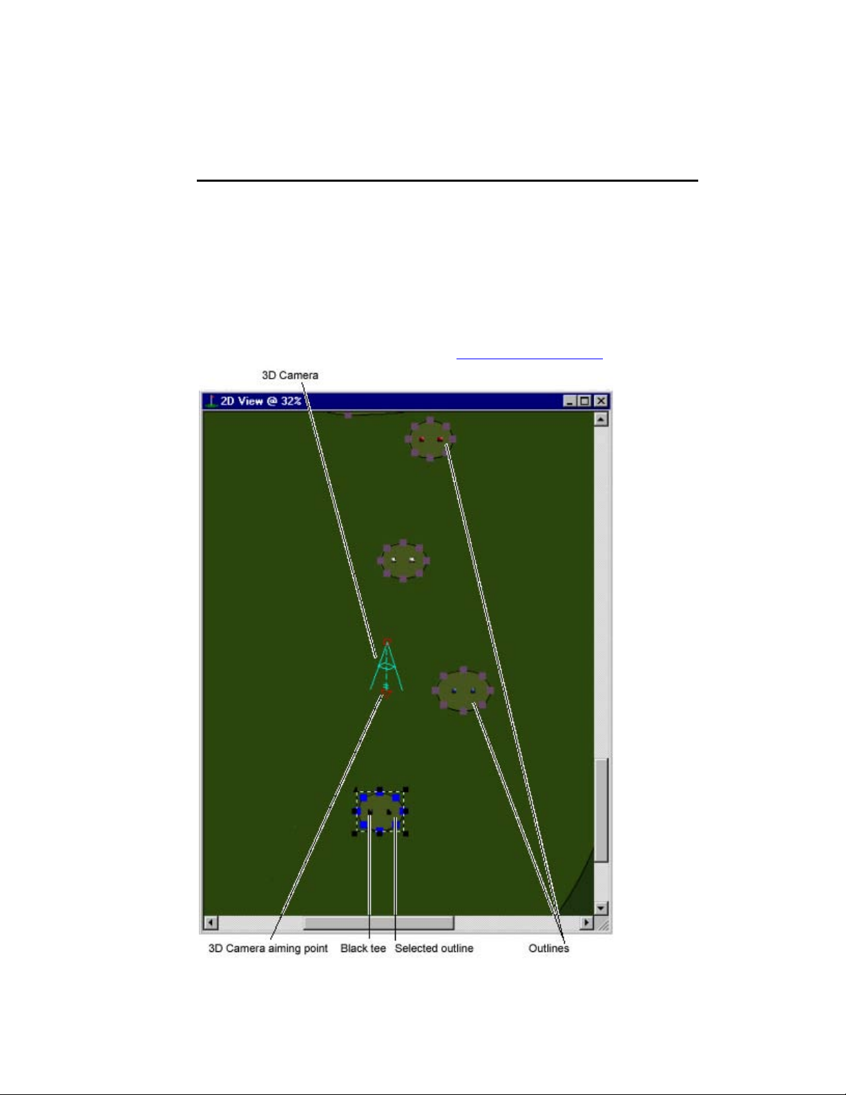
2D V
2D View gives you the best perspective on the entire hole. From this top-down
angle, you can see the outlines and objects that populate the hole. And you can
change the basic shape of your hole.
In 2D View, you place the 3D Camera, which aims the 3-dimensional view of the
hole from its lens in the 3D View window.
"
IEW
To edit the size of the hole’s terrain area after you have defined it in the New
Hole Wizard, click the HOLE INFORMATION button and use the
REGENERATE OUTLINES option. !!!! Hole Information pop-up.
Page 18
Page 19
Course Architect 2000
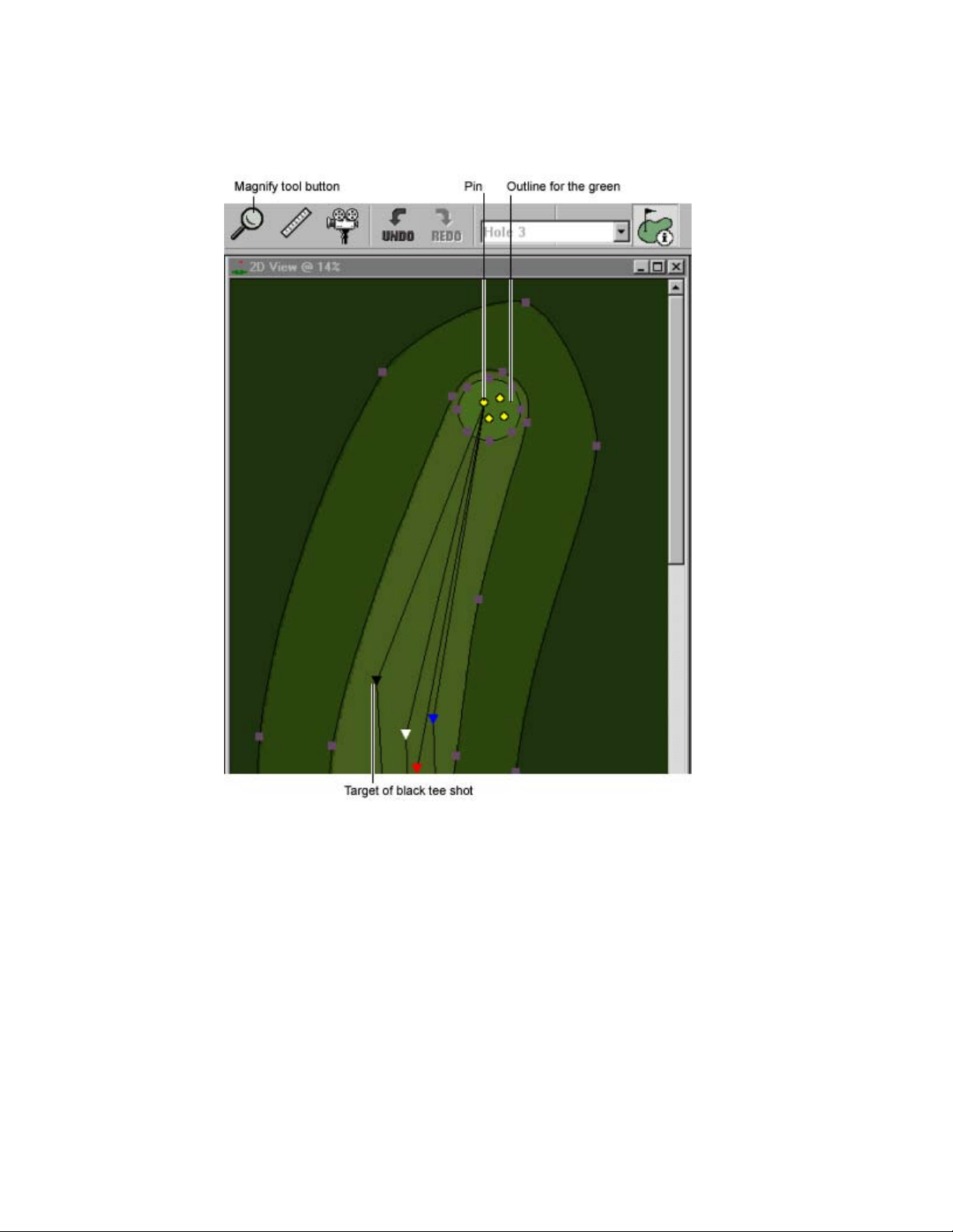
2D V
Often, a hole is too large to display entirely in 2D View at an acceptable level of
detail. The tool chooses to display the details, so you have to scroll the window or
resize it to view other parts of the hole. Or, you can zoom in on a specific area.
"
"
"
"
IEW DISPLAY
To zoom in and out on your hole, click the Magnify tool. To zoom in, left-click.
To zoom out, right-click. You can zoom in and out multiple times.
To scroll the 2D View window, use the scroll bars on the right and bottom
edge of the window.
To resize the 2D View window, select FIT from View. The window is resized
to fit into the available space.
To focus the 3D Camera on a location, select FOCUS ON SELECTION in the
Camera menu and double-click the target in 2D View. The camera now
focuses on your selection.
Page 19
Page 20
Course Architect 2000
: When using selection tools, maximize the 2D View window. The tools
N
OTE
perform much faster if you maximize the window and close 3D View.
O
UTLINES IN
"
To create, edit, or delete outlines in 2D View, click the Outlines tab. The
toolbar changes. Select the New Outline tool. Click, then drag to define the
control points of your outline. Double-click to finish shaping the outline. For
more, !!!! Outlines.
"
To define type of texture in your outline, click the Outline button then rightclick in it. Select PROPERTIES. Select the texture type and click OK. For
more, !!!! Outline and Texture Types.
U
PDATING
When the 2D View window is active, you can move the 3D Camera and update
the 3D View window.
"
To move the 3D Camera, press the arrow keys.
"
To update the 3D View window with your most recent changes in 2D View,
press [F2] or select UPDATE MASKS from the Outlines menu.
"
To update the 3D View window with the current shadows, press [F3] to
update Terrain shadows or [F4] to update Object shadows or both.
"
To toggle between opened 2D and 3D View windows, press [CTRL] + [TAB].
C
HANGING SHOT PATHS OF THE HOLE
In 2D View, you can alter the shape of the optimal shot paths from each tee. The
shot paths are lines that extend from each tee. Where the tee shot is supposed to
land, a colored triangle indicates the target. As soon as you start a hole, use the
Shot Path to tweak and finalize your tees and targets.
2D V
3D V
IEW
IEW
!
Shot paths are used to determine the basic yardage of a hole. Hole
yardages are displayed in the Scorecard. For more, !!!! The Scorecard.
The easiest way to move your tees and targets is to use the Shot Path tool and
then to regenerate the initial outlines to align them to the new shot path markers.
: Use the Regenerate Outlines function very carefully. When you
N
OTE
regenerate outlines, you reset the hole to the parameters set in the Hole
Options screen using the initial set of outlines. All additional outlines or other
changes to your hole are LOST. Regenerate outlines essentially resets the
hole based on the new Shot Paths.
If you need to move the pins and tee markers but do not want to regenerate
outlines, you can use the Shot Path tool to move them, close the tool, and then
move each underlying outline separately.
!
In the game, computer-controlled golfers use the shot paths to target their
initial shots.
"
To change the shot path, click and drag a control triangle to a new location.
"
To change the basic size of the hole, !!!! Hole Information pop-up.
Page 20
Page 21

Course Architect 2000
EA TIP As you develop a hole, check each shot path from time to time,
especially after you have populated it with objects that might interfere
with a computer-controlled golfer’s shots.
G
RID SIZE
You can layer a grid on top of 2D View. For placing and aligning objects and
outlines, it is a useful feature.
"
To toggle display of the grid, press CTRL + [G] or select GRID from the View
menu.
"
To change the size of the grid, select GRID SETTINGS from the View menu.
For more, !!!! 2D Grid Settings.
OLE INFORMATION POP-UP
H
The Hole Information pop-up allows you to reset the basic size and shape of the
core outlines (tees, fairway, and green) for the hole. You can read distance
information for each tee, adjust the size of the entire hole area, and reconfigure
the core outlines for the hole.
!
After a hole is started, you cannot change its par. You can change the
basic shape with manipulation of the outlines and their angles. However, if
you want to change the par, you need to delete the hole and start over. For
more, !!!! Erasing Your Work.
"
To toggle display of the Hole Information pop-up, press the Hole Information
button on the Hole tab.
"
To switch between the different tabs in the Hole Information pop-up, press
[CTRL] + [TAB].
T
EES
In the Tees tab, you can review the distance of each shot from each tab, plus the
total length for the hole.
T
ERRAIN SIZE
In the Terrain Size tab, you adjust the size of the terrain that includes and
surrounds the playable area of your hole. You can shrink or expand the left, right,
top, and bottom margins. The tool prevents you from clipping hole features such
as tees, pins, and aiming marks.
When you open this tab for the first time on a hole, each slider bar is positioned in
the middle.
"
To shrink or expand one side of the terrain, use the appropriate slider bar.
!
To undo a change in the terrain size, you can do the same change in the
opposite direction. You cannot undo manipulations to the terrain itself.
: Do not reduce the size of the terrain below the minimums suggested in
N
OTE
the Hole Information pop-up. Strange things may happen.
"
To apply your changes, click APPLY.
Page 21
Page 22
Course Architect 2000
EA TIP To improve performance in the game, you may want to trim off the
unused pieces of the terrain in the out-of-bounds areas.
R
EGENERATE OUTLINES
In the Regenerate Outlines tab, you can change the size of the core outlines for
your hole.
: Use the Regenerate Outlines function very carefully. When you
N
OTE
regenerate outlines, you reset the hole to the parameters set in the Hole
Options screen using the initial set of outlines. All additional outlines or other
changes to your hole are LOST. Regenerate outlines essentially resets the
hole based on the new Shot Paths.
!
In 2D View, a solid black outline indicates the Viewable Area. You can
adjust the width of this area, but you cannot adjust its shape.
"
To change the value for any of these features, click in the box and enter a
new number.
"
To apply changes to the hole, click APPLY. 2D View is updated.
"
To restore the default settings, click DEFAULTS.
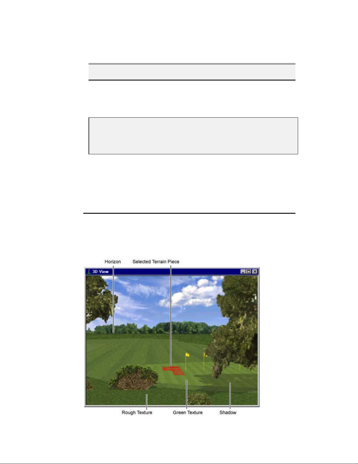
3D V
When developing 3D art on a computer, you are confronted with an irresolvable
fact: you cannot display three-dimensional objects on a 2D screen without some
form of interpretation. In Course Architect 2000, this interpretation is the 3D View
window.
IEW
Page 22
Page 23

Course Architect 2000
3D View displays what is viewed from the 3D Camera that is placed in the 2D
View screen. The 3D View window is your eye on the hole. If you were playing
the course as a golfer in the game, you would see the course as it is displayed in
3D View.
"
To toggle between opened 2D and 3D View windows, press [CTRL] + [TAB].
"
To focus the 3D Camera on a location, select FOCUS ON SELECTION in the
Camera menu and double-click the target in 2D View. The camera now
focuses on your selection.
The 3D camera is a powerful tool that gives you infinite perspectives on the
course. For more, !!!! 3D Camera.
T
ERRAIN
3D View is the best place to fine-tune your terrain features. While you can start
large-scale terrain features such as hills and ridges in 2D View, you give them
subtlety and definition in 3D View.
The multiple terrain selection tools allow you to highlight terrain pieces of any size
and shape. With the terrain tools, you raise, lower, tilt, flatten, smooth, and add
noise to them. For more, !!!! Terrain.
S
HADOWS
Shadows are displayed in 3D View. For terrain and objects, you can change the
position of the artificial sun and its characteristics in the Shadow Settings pop-up.
The shadows for terrain and sun are independent of each other. For more, !!!! Sun
and Shadows.
"
To update the 3D View window with the current shadows, press [F3] to
update Terrain shadows or [F4] to update Object shadows.
EA TIP If you have performed several terrain changes without seeing any
differences in the 2D View window, update the shadows. Update
Shadows redraws shadows for the entire hole. It takes considerable
CPU time and is not automatic because of its impact on slower
machines.
3D C
Like all good cameras, the 3D Camera in Course Architect 2000 can be
positioned at any angle to display the viewed terrain in the 3D View window. The
3D camera has two modes and gives you complete control over which course
features to display.
AMERA
!
Rendering the view of the 3D Camera can take time if you have a lowerend machine. For flexibility, Course Architect 2000 lets you choose what is
displayed in the 3D View window. For more, !!!! Camera Displays.
A N
OTE ABOUT
Movements in three-dimensional space can be described in three directions.
Stand up from your computer. Let's call the position where you are located, "Point
A."
3D D
IRECTIONS
Page 23
Page 24

Course Architect 2000
The X-direction refers to steps to the left or right of Point A.
The Y-direction refers to steps to forward and backward of Point A.
The Z-direction refers to changes in elevation from Point A. From where you're
standing, movements in the Z-direction require you to jump into the air or dig into
the ground. Before you get a shovel, let's get back to the computer.
Often, movements can be described in planes. A plane is a perfectly flat surface
that extends to infinity. Imagine an infinitely large top to your coffee table—a
plane. In 3D space, the X-Y plane refers to all of the positions that can be
described as movements in the X-direction or the Y-direction—not the Z-direction.
While you can describe movements in the other two planes (X-Z plane and Y-Z
plane), most planar movements in Course Architect 2000 are described in the XY plane and the Z-direction.
L
OCKED/FREE CAM MODES
The 3D Camera has two modes that govern the camera’s positioning and
movement: Locked Cam mode and Free Cam mode.
"
To switch between the 3D Camera modes, press the Locked/Free Cam mode
toggle button.
Locked Cam mode positions the camera at the scaled equivalent of six feet
above the surface of the course – a golfer’s point of view. In Locked Cam mode,
you can move the 3D Camera over the surface of the course but not in the
vertical plane.
"
To move the camera in Locked Cam mode, use the arrow keys.
Free Cam mode allows you to raise the camera above the plane of the course so
that you can get a bird’s eye view of your work. Free Cam mode has the 3D
display of Locked Cam mode combined with the perspective of the 2D View.
"
To move the camera across the X-Y (left-right/up-down) plane of the course
in Free Cam mode, use the arrow keys.
"
To move the camera in the vertical plane in Free Cam mode, use [CTRL] +
the arrow keys.
C
AMERA SETTINGS
The Camera Settings pop-up controls the location, mode, zoom, and sensitivity to
mouse changes of the 3D Camera.
"
To make finite changes to the camera’s X-Y positioning, enter numbers in the
appropriate text box and click APPLY. The 2D View and 3D View are
updated.
"
To change the angle of the camera, enter a number in the Angle text box.
"
To change the zoom factor in the camera, use the Zoom slider bar. 2D View
and 3D View are automatically updated.
You can toggle the Camera mode and establish settings for Free Cam mode.
"
To change the Camera mode, click the radio button next to the desired mode.
To move the Camera in the new mode, you must exit the Camera Settings
pop-up.
Page 24
Page 25

Course Architect 2000
When you put the camera in Free Cam mode, you can choose to float the camera
above the terrain at a fixed height, or you can set the camera to follow the
terrain’s contours at the selected height from it.
"
To set the altitude of the camera off of the terrain, enter a number in the ZOffset text box.
C
AMERA DISPLAYS
The information that you choose to display in 2D View and 3D View can
significantly impact the speed at which 3D View is updated. Under the Camera
menu, the render and display options affect display speed. Test different settings
in order to find the best options to balance speed and quality of the display
updates.
!
These camera settings are used to help you edit the course, but do not
affect the cameras in Tiger Woods 99 PGA TOUR Golf or Tiger Woods
PGA TOUR 2000.
The render options affect the display of textures on top of your terrain surfaces.
You can choose how the course is rendered in the 3D window:
R
ENDER
T
EXTURES
R
ENDER
F
LAT
R
ENDER
W
IRE
Render all textures in 3D View.
Render textures as flat-colored panels in 3D View.
Render 3D View as a wire-frame mesh of facets. Textures
are not displayed. Render Wire updates 3D View the
fastest.
Choosing to display various course and environment elements can affect update
speeds.
D
ISPLAY
C
AMERA
D
ISPLAY
O
BJECTS
D
ISPLAY
O
UTLINES
D
ISPLAY
F
AIRWAY
S
TRIPES
D
ISPLAY
W
ATER
R
EFLECTIONS
Toggles display of Camera Icon in 2D View.
Toggles display of objects in 3D View.
Toggles display of outlines in 3D View.
Toggles display of stripes from mowing on the fairway.
Toggles display of reflections in the water hazards.
For more information on the individual commands in the Camera menu, !
!
!!
Camera.
Page 25
Page 26
Course Architect 2000
COMMAND REFERENCE
The following sections contain reference information for menu and toolbar
commands.
ENUS
M
F
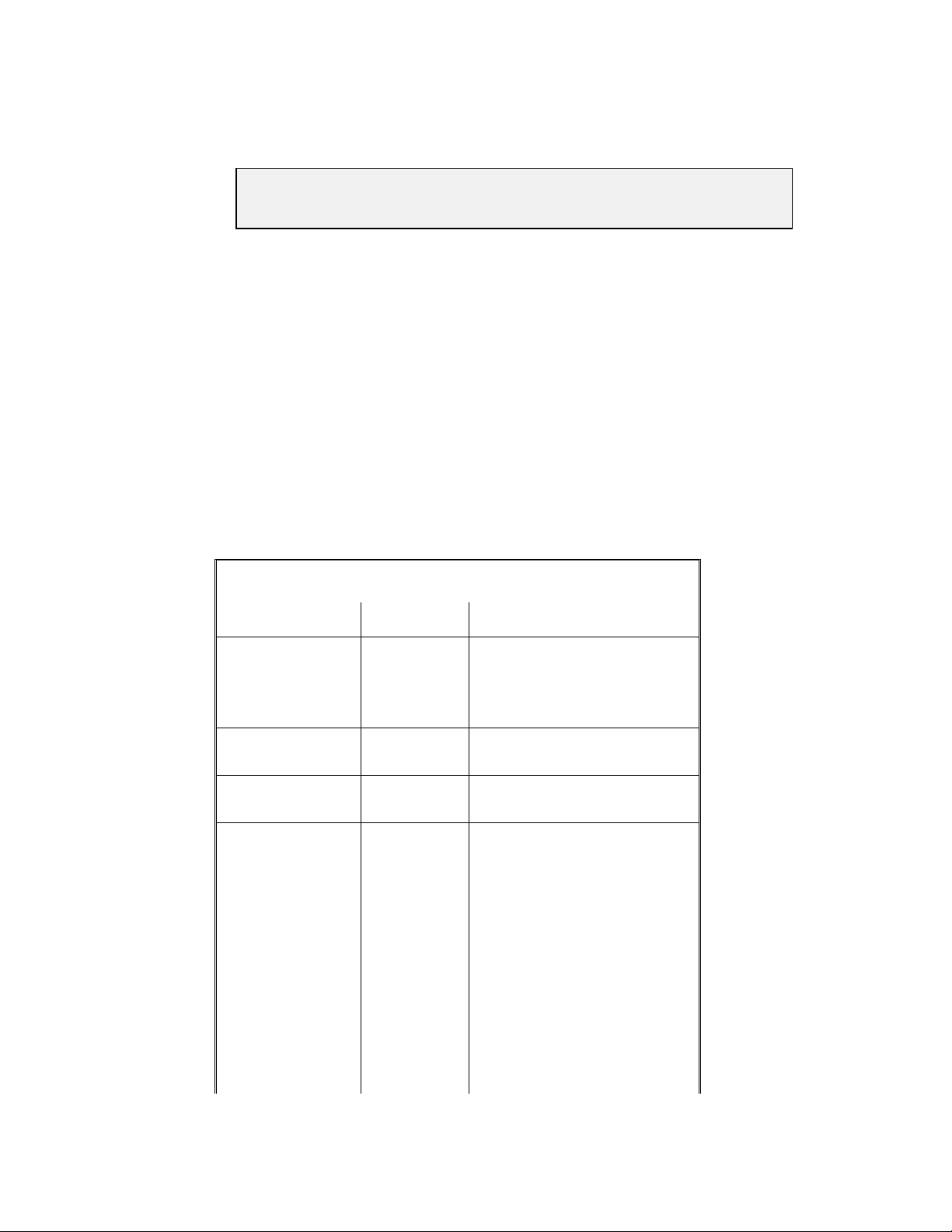
ILE
The File menu commands open, close, import, and export individual files.
ILE MENU
F
COMMAND KEYS
Open [CTRL] +
[O]
Close Close current hole.
Save [CTRL] +
[S]
Import Terrain Import Course Architect 2000
Export Terrain Export Course Architect 2000
Copy to Game Proof course and compile files
Open new project file.
Save current hole.
elevation data. For more, !
Import Terrain.
elevation data in various
formats. For more, !!!! Export
Terrain.
"
into game-ready format.
Copies compiled files to game
directory.
ESCRIPTION
D
!
!!
To save the file to a
different format, select it
from the File Type dropdown list. Add the proper
extension to the filename.
The tool automatically
saves the file to that
format.
Exit Exit the program.
P
ROJECT
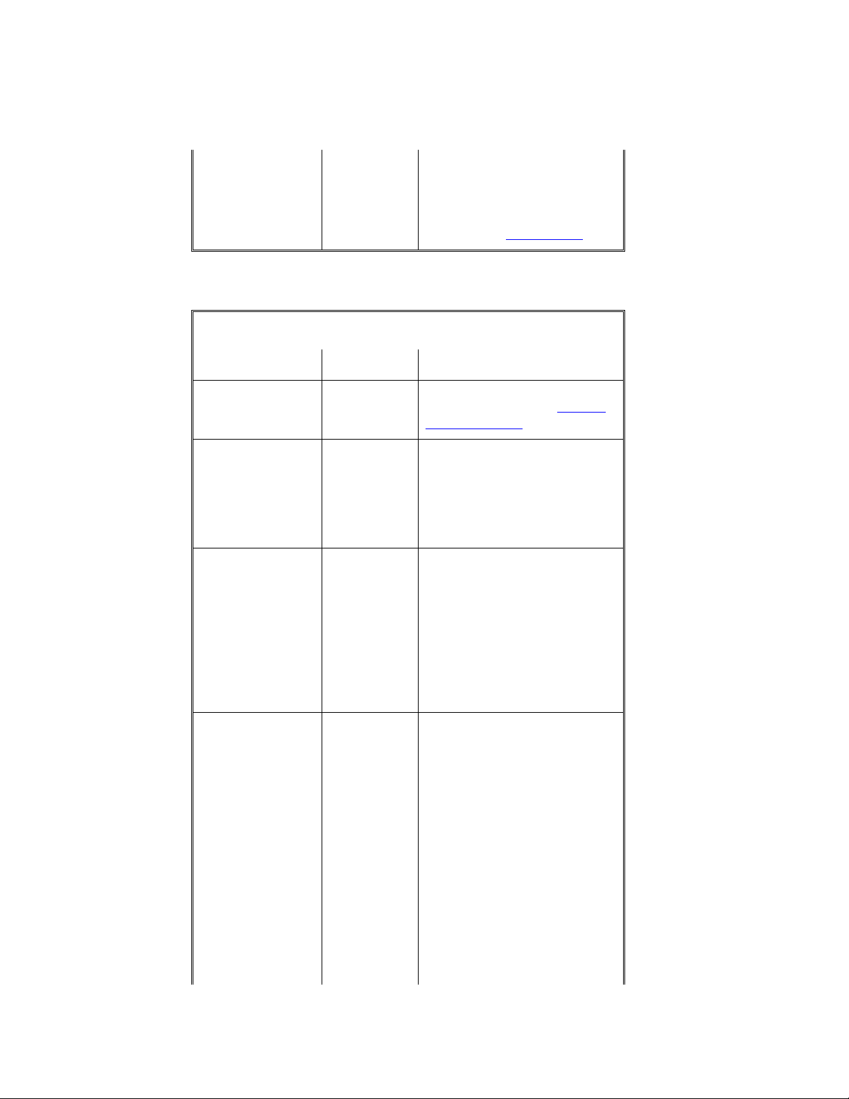
The Project menu items create, open, and close projects, as well as provide data
on the currently open project.
Page 26
Page 27
Course Architect 2000
ROJECT MENU
P
COMMAND KEYS
ESCRIPTION
D
New Start a new project. For more,
!
! Starting Projects.
!!
Open Open a project.
Close Close current project.
Info… Review memory usage and
object allocation for the current
project. For more, !
!
!!
Information pop-up.
Properties… Review and edit the source
directories for the project. You
can choose where to store
your project, object, texture,
and horizon files. For more, !
!
!!
Properties pop-up.
I
NFORMATION POP-UP
"
To toggle the display of memory usage in Kbytes or as a percentage, click
the radio button to the left of the measurement.
"
To close the window, click CLOSE.
EA TIP Avoid exceeding 100% Memory Usage for a hole. Memory Usage is
an absolute scale based on a minimum system. While your computer
may be able to handle a hole that exceeds the maximum usage, less
powerful machines may not be able to load your hole.
P
ROPERTIES POP-UP
The Properties dialog box is used primarily as a reference for the location of the
data files for your project.
: If you move your course's data directories through the Properties box,
N
OTE
strange things can happen, and your data can be corrupted. It is
recommended that you not move your directories. However, if you must do so,
use the following procedure.
To move your data directories:
Open the Properties dialog box. Write down the locations of your directories
1.
on a piece of paper.
Exit Course Architect 2000. In Windows, copy (don't cut) your data files from
2.
the source location to their new destination location. Write down the locations
of your new directories on a piece of paper.
Page 27
Page 28
Course Architect 2000
: Destination directories should be on your local machine. Do not load
N
OTE
data across networks or external media; performance in Course Architect
2000 may be impacted.
Restart Course Architect 2000. Load your course. In the Properties dialog
3.
box, change the locations to the new directories.
"
To apply the new directories to the project, click APPLY.
"
To cancel changes and exit, click CANCEL.
Save your course, and reload it. Look at a few holes. If the holes look to be in
4.
perfect shape, then you can exit to Windows and delete your source course
files.
If your holes look strange or do not load properly, you can revert to your
5.
source directories by entering the original locations in the Properties box.
Remember to delete the copied destination directories through Windows, as
they can occupy a significant amount of space.
E
DIT
The Edit menu contains standard editing commands and specialized tools for use
in Course Architect 2000.
DIT MENU
E
COMMAND KEYS
Undo [CTRL] + [Z] Undo last change.
!
Redo [CTRL] +
[Y]
Cut [CTRL] +
[X]
Copy [CTRL] +
[C]
Paste [CTRL] +
[V]
Delete [DEL] Delete selected object or
Move [CTRL] +
[D]
Redo last change.
Cut the selection and put it on
the clipboard.
Copy the selection to the
clipboard.
Copy the contents of the
clipboard to the selected
location.
outline.
Move the selected object to a
new location.
ESCRIPTION
D
Some changes such as
terrain resizing cannot
be undone.
Find… [CTRL] +
[F]
Search the hole for an object.
Optional replacement with
another object.
Page 28
Page 29
Course Architect 2000
Find in
Selection…
Edit Settings… [CTRL] +
[ENTER]
C
AMERA
The Camera menu manages the settings, position, and display of the 3D camera.
AMERA MENU
C
COMMAND KEYS
Camera
Settings…
Focus on
Selection
Render Textures [CTRL] +
[CTRL] +
[ALT] + [C]
[CTRL] +
[L]
[T]
Search the selection for an
object. Optional replacement
with another object.
Open the Edit Settings Screen.
For more, !!!! Edit Settings.
ESCRIPTION
D
Open the Camera Settings
Screen. For more, !!!! Camera
Settings Screen.
Focus the 3D camera on the
currently selected piece of
terrain. The camera doesn't
change its location. It rotates in
the direction of the selected
item.
In 3D View, render the camera
shot with textures included.
When ON, it is the default
setting for rendering.
!
Due to the large amount
of data in these
renderings, it may take
some time to render with
textures.
Render Flat [CTRL] +
[B]
Render Wire [CTRL] +
[W]
Display Camera [K] Toggle the display of the 3D
Display Objects [CTRL] +
[J]
In 3D View, render the camera
shot without elevation
information. The hole appears
as a flat plain.
In 3D View, render the camera
shot with the terrain rendered
as a red wire frame.
Camera icon in 2D View.
Toggle the display of objects
on the course.
"
To speed the updating of
3D View, set Display
Objects to OFF.
Page 29
Page 30
Course Architect 2000
Display Outlines [CTRL] +
[U]
Display Fairway
Stripes
Display Water
Reflections
S
ELECT
The Select tools allow you to create, edit, or delete features from your golf
course.
ELECT MENU
S
COMMAND KEYS
Clear All [C] Deselect all curren tly selected
New [N] When you select a new piece
Subtract [S] Each selected piece of terrain
Toggle the display of outlines
on the course.
Toggle the display of the
fairway stripes in 3D View.
Toggle the display of
reflections in the water in 3D
View.
ESCRIPTION
D
Terrain pieces.
of terrain, the tool forgets the
previous selection.
is removed from the
highlighted terrain.
Add… [A] Each selected piece of terrain
adds to the highlighted terrain.
Tool Lock [P] Lock the selected tool so that
you can use it multiple times in
a row.
Constrain
Texture
Grid [G] Selects the grid tool. The grid
Rectangle [R] Selects the rectangle tool. The
[X] When you select Constrain
Texture and then select a
terrain area, the highlighted
terrain is only the area that
shares the texture of the first
terrain facet that you touched.
tool lets you place a single
terrain piece of a
predetermined grid size. To
change the grid size, !!!! Grid
Size.
rectangle tool defines terrain
pieces of any size in the shape
of a rectangle.
Page 30
Page 31

Course Architect 2000
Freehand [F] Selects the freehand tool. The
freehand tool lets you draw
with the mouse a single, open
line of terrain.
Corral []] Selects the corral tool. The
corral tool allows you to draw
the outline of an area and
select the facets inside that
area.
Pick Texture [.] Selects the Pick Texture tool.
The pick texture tool selects
all of the connected facets that
share the texture of the facet
that you click.
Object [O] Toggle selection of objects
ON/OFF. When set to ON, you
can select Objects.
Outline [U] Toggle selection of outlines
ON/OFF. When set to ON, you
can select Outlines.
Elevation [E] Toggle selection of elevation
terrain ON/OFF. When set to
ON, you can select Terrain.
Grid Size… [ALT] +
[G]
O
UTLINES
Outline tools create, edit, and delete outlines that are laid on your course. For
more detailed information on outlines, !!!! Outlines.
UTLINES MENU
O
COMMAND KEYS
New Path Create a new cart path. For
The Grid tool selects a single
grid, the size of which is
determined in the Grid Size
pop-up. To change the grid
size, !!!! Grid Size.
ESCRIPTION
D
more, !!!! How to Create a Cart
Path.
New Outline Create a new outline.
Delete Point Delete the selected control
point in the outline.
Reset Tangent Reset the tangent for the
selected control point in the
Page 31
Page 32

Course Architect 2000
outline.
Move Forward Move the outline one layer up
(forward toward the 2D
camera).
Move Back Move the outline one layer
back (away from the 2D
camera).
Move to Top Move the outline to the top
layer.
Move to Bottom Move the outline to the bottom
layer.
Rotate… "
Scale… Expand or shrink the X- and Y-
Set Tangent
Scale Factor…
Add Point After Create a new control point
Add Point Before Create a new control point
Use the slider bar to rotate
the outline 0 to 360
degrees in the clockwise
direction.
scale of the outline.
"
To scale the outline, enter
values less than 1.0 in the
dialog box.
Set the precision at which
rotations a control point’s
tangent are controlled by the
mouse. For more, !!!! Setting
Tangent Scale.
between the selected control
point and the next one on the
purple segment.
between the selected control
point and the next one on the
yellow segment.
Update Masks [F2] Update 3D View based on the
current state of hole objects,
terrain, and outlines.
Bounding Box Toggle display of the bounding
box of the selected outline.
Border/Spine Toggle display of the black
border or spine of the selected
outline.
Properties… Review and edit the properties
of the outline. For more, !
Changing the Outline
!
!!
Page 32
Page 33

Course Architect 2000
Properties.
T
ERRAIN
The Terrain tools raise and lower terrain on your course and tweak its shape. For
more detailed information on terrain, !!!! Terrain.
EA TIP For a better appearance and improved playability, use the terrain tools
in conjunction with the Smoothing tool.
ERRAIN MENU
T
COMMAND KEYS
Mesa [M] Use the mouse to create a
flattened plateau or valley with
steep edging for the selected
terrain.
Tilt [T] Use the mouse to tilt selected
terrain to the left or right. Set
the anchor point and then drag
the tilt.
Bump [B] Use the mouse to create a
concave or convex bump with
a soft, rounded top or bottom.
The Bump tool automatically
smoothes its features into the
surrounding terrain.
Linear [L] Use the mouse to pull the
center point of the selected
terrain straight up or down.
Smooth… [H] Blend the features of the
selected terrain into smoother
curves. For more, !
Smoothing Terrain.
ESCRIPTION
D
!
!!
Flatten… [W] Set a maximum height or
depth for the selected terrain.
For more, !!!! Flattening
Terrain.
Raise/Lower… Raise or lower the selected
terrain a defined number of
feet. For more, !!!! Raising and
Lowering Terrain.
Add Noise… Add random undulations to the
selected terrain and smooth it,
as needed. For more, !
Adding Noise to Terrain.
!
!!
Page 33
Page 34

Course Architect 2000
Drop Object Use the mouse to click on a
location in 2D or 3D View to
drop the selected object.
Adjust Size… Change the size of the terrain
for the hole. For more, !
Terrain Size.
!
!!
Ambient
Sound…
EA TIP The Tilt tool is excellent for defining large, sloping hillsides.
S
HADOWS
The Shadow menu items let you change the parameters governing sun shadows
on the course and update the 3D camera with the latest shadows.
HADOWS MENU
S
COMMAND KEYS
Shadow
Settings…
Update Terrain
Shadows
Update Object
Shadows
[F3] Re-render the 3D View with
[F4] Re-render the 3D View with
!
Set the collection of
ambient sounds that are
loaded with the hole. For
more, !!!! Ambient Sound.
ESCRIPTION
D
Configure the artificial sun and
shadow settings for the hole.
For more detailed information
on outlines, !!!! Sun and
Shadows.
updated terrain shadows.
updated object shadows.
V
IEW
The View tools control the appearance of the desktop, 2D View, and 3D View
windows.
IEW MENU
V
OMMAND KEYS
C
Small Icons Toggle size of toolbar icons
SMALL/LARGE.
Toolbar Toggle display of toolbar.
Status Bar Toggle display of status bar at
the bottom of the screen.
2D View… Open another 2D View window
on the hole.
ESCRIPTION
D
Page 34
Page 35

Course Architect 2000
!
Changes in one 2D View
window appear in the
other window, too.
3D View… Toggles display of 3D View
window.
!
You can have only one
3D View window open at
a time.
Textures… Opens the texture library. For
more, !!!! Textures.
Objects… Opens the Object Browser. For
more, !!!! Objects.
Horizons… Opens the horizons and skies
library. For more, !!!! Horizons
and Skies.
Score Card Toggles display of the
Scorecard, which contains
yardage, difficulty, and other
course information. For more,
!
! Score Card.
!!
25% Sets display of 2D View
window at 25% magnification.
50% Sets display of 2D View
window at 50% magnification.
100% [CTRL] + [0]
(zero)
200% Sets display of 2D View
Magnify Selects the Magnify tool.
Fit [ALT] + [0]
(zero)
Grid [CTRL] +
[G]
2D Grid
Settings…
[ALT] +
[CTRL] +
[G]
Sets display of 2D View
window at 100% magnification.
This is the default setting.
window at 200% magnification.
"
To zoom in on a part of the
hole, left-click on it. You
can zoom multiple times.
"
To zoom out, right-click.
Adjust the size of the current
window to fit your monitor
screen.
Toggle display of grid overlay
in 2D View.
Adjust the width and height of
the 2D grid, when displayed.
You can change the unit of
measurement between pixels
Page 35
Page 36

Course Architect 2000
on your computer screen and
yards in the game. In game
data, a pixel converts to 1/16
of a yard. For more, !!!! 2D Grid
Settings.
2D G
RID SETTINGS POP-UP
"
To change the width and height of the 2D grid, enter numbers in the
appropriate boxes. Or, use the slider bars.
"
To apply the changes, click APPLY.
"
To close the window, click CLOSE.
W
INDOW
Window tools let you arrange how multiple windows are displayed on-screen.
INDOW MENU
W
th
COMMAND KEYS
Cascade Displays the opened windows
in a cascading pattern.
Tile Tiles the windows so that you
can see each opened window.
H
ELP
Use the Help tools to get more information on Course Architect 2000.
ELP MENU
H
COMMAND KEYS
Help Topics Opens the help system.
About
Architect…
AB TOOLBARS
T
Course Architect 2000 has four different toolbar tabs. The tools on each tab
control a different area of course development.
Displays version number and
copyright information for
Course Architect 2000.
ESCRIPTION
D
ESCRIPTION
D
"
To use any tool, click the tool button in the toolbar. Then use the mouse to
point, click, and drag a selected item.
H
OLE TAB
Use the Hole tab to add or to open a different hole on the course. In Course
Architect 2000, you work with one hole at a time.
Page 36
Page 37

Course Architect 2000
E
DIT TOOLS
Use these tools to undo and redo changes. You can configure the number of
Undo’s in the Edit Settings Screen. For more, !!!! Edit Settings Screen.
U
NDO
R
EDO
V
IEW TOOLS
M
AGNIFY
Undo the most recent change.
Redo the change that was most recently undone.
The Magnify tool allows you to zoom in and out over a
selected area in 2D View.
"
To zoom in on a part of the hole, left-click on it. You can zoom multiple times.
"
To zoom out, right-click.
R
ULER
Use the Ruler tool to measure distances between points
on the course in 2D View. With the assistance of the
Ruler, you can tailor the hole to require particular clubs
for the best approach to the green.
"
To measure a distance between two points, click on a starting point and drag
the mouse while keeping the mouse button pressed. The distance is
displayed next to the mouse pointer.
L
OCKED
/F
REE CAM
T
OGGLE
The L
OCKED/FREE
Cam Toggle switches between Locked
Cam mode and Free Cam mode.
Locked Cam mode positions the 3D Camera about six feet off the surface of the
hole–at a golfer’s viewpoint.
Free Cam mode lets you move the camera in the vertical plane to get the best
perspective of an area under construction. For more, !!!! Locked/Free Cam
Modes.
H
OLE TOOLS
S
ELECT HOLE
To create or edit a new hole, select the hole number from
the drop-down list.
If you have not yet created the new hole, the New Hole Wizard begins. For more,
!
! New Hole Wizard.
!!
H
OLE
I
NFORMATION
T
ERRAIN TAB
Toggles display of the Hole Information pop-up. For more,
!
! Hole Information pop-up.
!!
The Terrain tab contains the tools to manipulate the terrain geometry of the hole.
For more, !!!! Terrain.
Page 37
Page 38

Course Architect 2000
E
DIT TOOLS
Use these tools to undo and redo changes. You can configure the number of
Undo’s in the Edit Settings Screen. For more, !!!! Edit Settings Screen.
U
NDO
R
EDO
V
IEW TOOLS
M
AGNIFY
Undo the most recent change.
Redo the change that was most recently undone.
The Magnify tool allows you to zoom in and out over a
selected area in 2D View.
"
To zoom in on a part of the hole, left-click on it. You can zoom multiple times.
"
To zoom out, right-click.
R
ULER
Use the Ruler tool to measure distances between points
on the course in 2D View. With the assistance of the
Ruler, you can tailor the hole to require particular clubs
for the best approach to the green.
"
To measure a distance between two points, click on a starting point and drag
the mouse while keeping the mouse button pressed. The distance is
displayed next to the mouse pointer.
L
/
OCKED
F
REE CAM
T
OGGLE
The L
OCKED/FREE
Cam Toggle switches between Locked
Cam mode and Free Cam mode.
Locked Cam mode positions the 3D Camera about six feet off the surface of the
hole–at a golfer’s viewpoint.
Free Cam mode lets you move the camera in the vertical plane to get the best
perspective of an area under construction. For more, !!!! Locked/Free Cam
Modes.
S
ELECTION TOOLS
O
UTLINE
Press [U] to use the Outline tool to select outlines in 2D
View.
F
REEHAND
R
ECTANGLE
Use the Freehand tool to draw an open, single line of
terrain. It's useful for placing objects along or path or for
making a fence.
The Rectangle tool lets you select a rectangular piece of
terrain.
Page 38
Page 39

Course Architect 2000
G
RID
The Grid tool selects a single grid, the size of which is
determined in the Grid Size pop-up. To change the grid
size, !!!! Grid Size.
C
ORRAL
The Corral tool lets you draw by freehand a closed set of
facets and to select all of the facets within that set.
P
ICK
T
EXTURE
The Pick Texture tool lets you select all of the connected
terrain facets that share the texture of the facet that you
first touched.
C
ONSTRAIN
T
EXTURE
When you select Constrain Texture and then select a
terrain area, the highlighted terrain comprises the areas
that share the texture of the first terrain facet that you
touched.
T
OOL LOCK
Locks the selected tool so that you can use it multiple
times in a row.
: When using selection tools, maximize the 2D View window. The tools
N
OTE
perform much faster if you maximize the window and close 3D View.
T
ERRAIN TOOLS
The Terrain tools assist you in adding shape to your terrain. With your mouse,
you can use these tools to raise/lower or move left/right the terrain in the shapes
described below.
M
ESA
Use the mouse to create a flattened plateau or valley for
the selected terrain.
B
UMP
L
INEAR
Use the mouse to create a concave or convex bump.
Use the mouse to pull the center point of the selected
terrain straight up or down.
T
ILT
E
LEVATION TOOLS
Use the mouse to tilt selected terrain to the left or right.
Elevation tools allow you to raise or lower a selected piece of terrain by a defined
number of feet. When you select one of these tools, you enter the number of feet
that you wish the tool to apply to the terrain.
F
LATTEN
Set a maximum height or depth for the selected terrain.
For more, !!!! Flattening Terrain.
R
AISE/LOWER
Raise or lower the selected terrain a defined number of
feet. For more, !!!! Raising and Lowering Terrain.
S
MOOTH
Blend the features of the selected terrain into smoother
curves. For more, !!!! Smoothing Terrain.
"
To open the Smooth pop-up, press [H].
N
OISE
Add random undulations to the selected terrain and
smooth it, as needed. For more, !!!! Adding Noise to
Terrain.
Page 39
Page 40

Course Architect 2000
O
UTLINE TAB
The Outline tab holds the tools to manipulate outlines. In Course Architect 2000,
outlines are shapes that cover the surface geometry of a hole. The various
textures applied to outlines determine appearance and place characteristics of an
area of the course.
E
DIT TOOLS
Use these tools to undo and redo changes. You can configure the number of
Undo’s in the Edit Settings Screen. For more, !!!! Edit Settings Screen.
U
NDO
R
EDO
V
IEW TOOLS
M
AGNIFY
Undo the most recent change.
Redo the change that was most recently undone.
The Magnify tool allows you to zoom in and out over a
selected area in 2D View.
"
To zoom in on a part of the hole, left-click on it. You can zoom multiple times.
"
To zoom out, right-click.
R
ULER
Use the Ruler tool to measure distances between points
on the course in 2D View. With the assistance of the
Ruler, you can tailor the hole to require particular clubs
for the best approach to the green.
"
To measure a distance between two points, click on a starting point and drag
the mouse while keeping the mouse button pressed. The distance is
displayed next to the mouse pointer.
L
/
OCKED
F
REE CAM
T
OGGLE
The L
OCKED/FREE
Cam Toggle switches between Locked
Cam mode and Free Cam mode.
Locked Cam mode positions the 3D Camera about six feet off the surface of the
hole–at a golfer’s viewpoint.
Free Cam mode lets you move the camera in the vertical plane to get the best
perspective of an area under construction. For more, !!!! Locked/Free Cam
Modes.
O
UTLINE TOOLS
O
UTLINE
Click the Outline tool to select outlines.
Page 40
Page 41

Course Architect 2000
N
EW OUTLINE
Click the New Outline tool to create a new outline. For
more, !!!! Outlines.
N
EW PATH
Click the New Path tool to create a new cart path, a
special kind of outline. For more, !!!! How to Create a Cart
Path.
P
OINT TOOLS
D
ELETE
P
OINT
!
You cannot delete a control point if the number of points in the outline is
Click the Delete Point tool to delete the highlighted control
point.
three.
R
ESET
T
ANGENT
S
ET TANGENT
A
NGLE
Resets the tangent for the selected control point to its
original placement.
Set the precision at which movements of the mouse
rotate a control point's tangent. Set the precision at which
rotations a control point’s tangent are controlled by the
mouse. For more, !!!! Setting Tangent Scale.
A
DD POINT
A
FTER
Create a new control point between the selected control
point and the next one. When you select a control point
on an outline, points added after the control point are
placed on the purple line.
A
DD POINT
B
EFORE
Create a new control point between the selected control
point and the next one in. When you select a control point
on an outline, points added before the control point are
placed on the yellow line.
L
AYER TOOLS
M
OVE
F
ORWARD
M
OVE BACK
M
OVE TO
F
RONT
M
OVE TO
B
ACK
!
When you move an outline to a new layer, you are moving it relative to all of
Move the outline one layer up.
Move the outline one layer back.
Move the outline to the top layer.
Move the outline to the bottom layer.
the outlines on the hole—not just the ones that it overlaps.
P
OSITION TOOLS
R
OTATE
Rotate the outline a number of degrees in the clockwise
direction.
P
ROPERTIES
O
BJECT TAB
Open outline’s Properties window. For more, !!!! Changing
the Outline Properties.
Page 41
Page 42

Course Architect 2000
With the tools in the Object tab, you can load and place objects from the library of
Course Architect 2000. The library contains varieties of rocks and trees,
combinations of which can be populated over a selected area.
E
DIT TOOLS
Use these tools to undo and redo changes. You can configure the number of
Undo’s in the Edit Settings Screen. For more, !!!! Edit Settings Screen.
U
R
NDO
EDO
Undo the most recent change.
Redo the change that was most recently undone.
V
IEW TOOLS
M
AGNIFY
The Magnify tool allows you to zoom in and out over a
selected area in 2D View.
"
To zoom in on a part of the hole, left-click on it. You can zoom multiple times.
"
To zoom out, right-click.
R
ULER
Use the Ruler tool to measure distances between points
on the course in 2D View. With the assistance of the
Ruler, you can tailor the hole to require particular clubs
for the best approach to the green.
"
To measure a distance between two points, click on a starting point and drag
the mouse while keeping the mouse button pressed. The distance is
displayed next to the mouse pointer.
L
/
OCKED
F
REE CAM
T
OGGLE
The L
OCKED/FREE
Cam Toggle switches between Locked
Cam mode and Free Cam mode.
Locked Cam mode positions the 3D Camera about six feet off the surface of the
hole–at a golfer’s viewpoint.
Free Cam mode lets you move the camera in the vertical plane to get the best
perspective of an area under construction. For more, !!!! Locked/Free Cam
Modes.
S
ELECTION TOOLS
R
ECTANGLE
The Rectangle tool lets you select a rectangular piece of
terrain.
G
RID
The Grid tool selects a single grid, the size of which is
determined in the Grid Size pop-up. To change the grid
size, !!!! Grid Size.
Page 42
Page 43

Course Architect 2000
C
ORRAL
The Corral tool lets you draw by freehand a closed set of
facets and to select all of the facets within that set.
P
ICK
T
EXTURE
The Pick Texture tool lets you select all of the connected
terrain facets that share the texture of the facet that you
first touched.
C
ONSTRAIN
T
EXTURE
When you select Constrain Texture and then select a
terrain area, the highlighted terrain comprises the areas
that share the texture of the first terrain facet that you
touched.
T
OOL LOCK
Locks the selected tool so that you can use it multiple
times in a row.
P
OPULATE
Place multiple objects of different types in a selected
area.
: When using selection tools, maximize the 2D View window. The tools
N
OTE
perform much faster if you maximize the window and close 3D View.
Page 43
Page 44

Course Architect 2000
EDIT SETTINGS SCREEN
The Edit Settings screen allows adjustment to mouse and display settings. Also,
you can set the number of previous changes that are retained in memory.
"
To open the Edit Settings Screen, press [CTRL] + [ENTER] or select
OPTIONS from the Edit menu.
"
To apply your changes in the Edit Settings Screen, click APPLY.
!
You can apply changes in the Edit Settings Screen and check their effects
in the desktop.
"
To cancel your changes and exit, click CANCEL.
: If you have already clicked apply, your changes cannot be canceled.
N
OTE
"
To accept your changes and exit, click OK.
OUSE SENSITIVITY
M
The Mouse Sensitivity settings dictate the responsiveness of the terrain changes
to mouse movements. For each type of terrain change, you can alter how the
program responds when you move the mouse.
EA TIP Set your mouse sensitivities to suit your editing style or subsequent
tasks. If you like to make precise, detailed terrain edits, set the mouse
sensitivities to lower levels. If you want to move lots of terrain quickly,
set them to higher levels.
INES
L
When you draw lines with the selection tools, these colors represent the various
states of your lines.
"
To change a line color, double-click in the colored box. Select a new color
from the palette and click OK.
UTLINES
O
Under the Outlines tab, you set the colors for points and segments in outlines.
For line segments, Normal color indicates the edge of the outline when the outline
has been selected. When you select a control point, the Before Color indicates
the line segment before the control point, while the After Color indicates the one
after it.
You can set the colors of the points themselves. When an outline has been
highlighted, the control points appear in the Normal Color. When you click on a
control point, it appears in Active Color, and its two tangent points appear in
Tangent Color.
"
To change a color, double-click in the colored box. Select a new color from
the palette and click OK.
Page 44
Page 45

Course Architect 2000
You can change the offset for displaying a secondary, cascading window. The
Stagger values indicate how far to the right (X) and down (Y) of the top-left corner
of the first window the program opens the second window.
At the bottom of the Outlines tab, you can configure how pasted objects appear
relative to the parent object. By setting the X and Y figures using the slider bar,
you establish how many pixels to the right (X) and down (Y) from the parent
object each subsequent object is pasted.
"
To set the Stagger X and Stagger Y, use the appropriate slider bars.
AMERA
C
The Camera settings define the appearance of the 3D Camera icon in the 2D
View.
"
Set the size of the icon to SMALL, MEDIUM, or LARGE.
You can define the colors that are used to indicate the aiming arrow, the body of
the icon, and when the icon is active.
"
To choose a new color, double-click in the color box. Select a new color from
the palette and click OK.
NDO
U
You can set the number of Undo’s that are retained in memory. If you have a
computer with the recommended amount of memory, you may appreciate this
feature during development. If you have a computer with the minimum amount of
memory (! System Requirements), set the number of Undo's lower. You will
likely find that ten undo's is usually sufficient.
"
To set the number of Undo’s from 1 to 30, use the slider bar.
"
To prevent Undoing, leave Undo Selections box empty.
If an action cannot be undone, you can decide how the tool alerts you.
"
To force the tool to ask you before completing the action, select ASK.
"
To proceed without asking, select PROCEED.
"
To cancel the action, select CANCEL.
"
To also alert you with a beep, select BEEP.
Page 45
Page 46

Course Architect 2000
STARTING PROJECTS
Starting is easy; finishing takes some work, but hopefully, the work is fun in
Course Architect 2000.
!
Prior to starting Course Architect 2000, you should set your display to 800 x
600 or higher in the Display control panel. For information on how to set it,
see your Windows documentation.
"
To start Course Architect 2000, double-click the Course Architect 2000 icon.
The program opens.
!
You cannot open Course Architect 2000 by double-clicking a project (.JPJ)
file.
If you have sufficient hard drive space, you can work on multiple projects and
share data between them. This chapter discusses how to get started.
: When you are using Course Architect 2000, it is highly recommended
N
OTE
that you close all other programs, including Tiger Woods 2000. The tool needs
as much RAM as your system can maximally provid e.
EW COURSE WIZARD
N
Course Architect 2000 stores projects as a series of files and folders inside the
Course Architect directory. When you start a new project, you name its holding
folder the name of your course. For example, if you’re building a course called,
“Rolling Hills,” you should name your folder, “Rolling Hills”.
To get you started, the New Course Wizard gathers some basic information about
your course and how you want to store it. When you complete the New Course
Wizard, you’re ready to begin designing.
When you have completed a project, Course Architect 2000 assembles all of the
outlines, textures, objects, and terrain files that are required into a location that
your installed Tiger Woods PGA TOUR golf game can access.
To start a new project, you should check first to see that you have enough space.
To start, you want at least 210MB of free hard drive space.
To start a new project:
Course Architect 2000 from EA SPORTS lets you build the golf course of your
dreams. Or you can recreate any of the twenty-seven courses on the PGA
TOUR®. A specialized suite of graphical tools puts the bulldozers, landmovers,
and lawn mowers at your fingertips.
!
You cannot open Course Architect 2000 by double-clicking a project (.JPJ)
file.
"
To start a new project, select NEW from the Project menu. The New Course
Wizard steps you through the setup.
!
After the course file is initialized, do not change the names and locations of
the course files on your hard drive.
To start a new course:
Page 46
Page 47

Course Architect 2000
Select NEW from the Project menu. The New Course Wizard begins.
1.
Enter the name of your course in the provided box.
2.
"
To place your course in a different location than the directory listed onscreen,
click BROWSE. Navigate to a new location.
!
When complete, an eighteen-hole course ready for export can occupy up to
200MB, depending on the size and nature of your course. When packed for
use in the game, a course takes 50-60MB.
"
To select the current folder in the Browse window, click SELECT.
"
To cancel the New Course Wizard, click CANCEL.
In the next screen, you can read the name of your course and its location.
3.
"
To change any of the information, click BACK.
"
To cancel the New Course Wizard, click CANCEL.
Page 47
Page 48

Course Architect 2000
"
To continue, click NEXT.
"
To finish creating your course, click FINISH.
Your course is now created. Course Architect 2000 copies the default data
4.
directories into sub-directories inside your course folder.
!
The default data files are about 12MB.
When you have finished the Project Wizard, the New Hole Wizard begins on
5.
Hole #1. For more, !!!! New Hole Wizard.
!
Although you may complete your hole designs in any order, you must
create Hole #1 first. We recommend that you build your course from Hole 1
to Hole 18.
EA TIP Do not change the names of the folders of your course, or your data
can be corrupted.
Y
OUR FILES AND THEIR LOCATION
After you have started your project, do not move files to different folders. Do not
change filenames. The tool may be unable to find necessary files.
Inside Course Architect 2000 directories, the following relative directories store
the source data files:
!
Objects: (course name)\objects
!
Textures: (course name)\textures
!
Horizons: (course name)\horizons
You can find other objects, textures, and horizons in the LIBRARY directory at the
root of your Course Architect 2000 CD, or the Library folder on your hard drive.
As you build your course, the number of files associated with it continues to grow.
"
To export your course for game use, select COPY TO GAME from the File
menu. The project file is compiled into a single game-course file and placed in
Page 48
Page 49

Course Architect 2000
the appropriate directory for access from inside Tiger 99 PGA TOUR Golf or
Tiger Woods PGA TOUR 2000.
W
HEN USING COURSE ARCHITECT
Your project may take more than one day to complete. It’s a good idea to
back up your work on a regular basis.
AVING YOUR WORK
S
When you are loading and saving projects, keep the data on a local drive. Do not
store your projects on external media or on a connected network. Performance
can be significantly impacted.
"
To save the current hole, select SAVE from the File menu.
"
To close the project, select CLOSE from the Project menu. If prompted, save
your project.
: Do not change the names of any Course Architect 2000 data files
N
OTE
outside of the tool. It can produce odd results or fatal crashes in the tool. To
modify Course Architect 2000 data files, it is best to work with copies and re-
import the files through the tool.
S
AVING HOLES
When you save a hole, you may receive an error message indicating that Course
Architect 2000 is unable to create a hole directory. Course Architect 2000 has
discovered a previously created hole and cannot overwrite it.
If you want to overwrite the hole, you must delete the hole folder outside of
Course Architect 2000 and attempt to resave the hole inside the tool.
2000, save your work on a regular basis.
OADING A PROJECT
L
To load your project, you load the project file that is stored in the course directory.
"
To load a project, select OPEN from the Project menu. Navigate to the folder
where you initially saved your project. Select the .JPJ file and press OPEN.
Your project opens.
!
If you cannot see your project file, select the .JPJ file type.
When you are loading and saving projects, keep the data on a local drive. Do not
store your projects on external media or on a connected network. Performance
can be significantly impacted.
MPORTING
I
!
You can import various types of source materials. Each material type has
different format and size constraints which you must configure in your
external development tools. For more, !!!! Import/Export.
RASING YOUR WORK
E
Page 49
Page 50

Course Architect 2000
In Course Architect 2000, mistakes aren’t as costly as on a real golf course.
Instead of rehiring the landmovers, contractors, and labor to correct mistakes, a
few mouse clicks can undo or erase your worst blunders.
U
NDO
If you make a simple mistake, Undo it.
"
To undo the last action, press [CTRL] + [Z].
"
To redo the last action, press [CTRL] + [Y].
!
Some actions cannot be undone. The tool prompts when an action cannot
be undone.
You can undo multiple times. Suppose you realize, ten steps later, that you made
a mistake. If you Undo ten times, you can correct the mistake.
You can set the number of Undo’s that the program remembers—up to 30.
"
To redo the last action, go to the Undo tab in the Edit Settings Screen. For
more, !!!! Edit Settings Screen.
D
ELETING HOLES
You may decide that it is easier to delete a hole instead of undoing your mistakes
and correcting them.
"
To delete a hole, go to Windows. Navigate to the project folder on your hard
disk. Delete the folder that is named “HoleXX” where XX represents the hole
number.
The hole is then deleted. To restart the hole, select the hole from the drop-down
list in Course Architect 2000. For more, !!!! New Hole Wizard.
XPORTING COURSES
E
Even if your course is not completed, you can export your course to the game to
test it. When you export a course, the tool saves the output files in the proper
directory for use in the game. Use this feature to test your partially completed
courses or to export finished courses for your system or to share with friends.
: You can export courses to Tiger Woods 99 PGA TOUR Golf and Tiger
N
OTE
Woods PGA TOUR 2000.
Depending on the size and number of defined holes in your course, an exported
file can be 50-60MB in size.
"
To export a course, select COPY TO GAME from the File menu. After the tool
checks the course, it places the course in the proper destination directory.
: To export a course to the game, you must have a Hole #1. Attempting
N
OTE
to play rounds across holes that have not been started can cause crashes in
some versions of the game. To test incomplete courses in the game, use
Practice Mode and select only holes that you have defined.
Page 50
Page 51

Course Architect 2000
LAYING OUT A COURSE
On a computer golf course, you don’t have to walk from hole to hole. When you
complete a hole, the computer simply places you at the tee for the next hole.
Consequently, you never see the course on a scale larger than the individual
hole.
However, the best courses in the world have a consistency from hole to hole. On
each hole, you can see familiar terrain shapes that are integrated into the
topography of the course location. When done right, this consistency has a
harmonious effect on the golfing experience. You feel like you’re in a peaceful
and carefully considered environment.
In Course Architect 2000, you build your course hole-by-hole. To account for
features and issues on a scale larger than the individual hole, you need to plan
ahead. This chapter provides some design points before you start digging.
ASIC DESIGN DECISIONS
B
D
RAMA VS
Before you begin to work on your course, you should make some essential
decisions. Are you making a realistic course or a fantasy course? Or are you
making something in between? Your decision can influence how you complete
your course. A realistic course requires more patience and adherence to predefined course features, including accurate terrain creation and sun and horizon
positioning.
C
OURSE LOCATION AND DEGREE OF DIFFICULTY
Secondly, you need to place your course in a particular climate and geological
environment. Is it a tropical course or an alpine course? How much does the
natural surrounding terrain impact the course? These decisions affect which
elements such as objects, textures, horizons, and terrain shapes are used on the
course.
You should also consider how difficult you want the course to be. Is it a
championship-level course? How long is the course? What is the par?
!
A standard format for a course is 4 par 3’s, 4 par 5’s, and the rest as par
4’s. Such an organization produces a par 72 course.
You should consider how you want to distribute the holes on your course. A par 3
hole doesn’t necessarily imply an easy hole; your tee shot could be very
challenging. Does your course get easier or harder as the holes progress? How
do you want the course to finish? On a par 5, so that a second-place golfer can
make up a stroke or two?
. R
EALISM
And finally, what elements of your course are going to stand out as unique? What
are its risks? What are its rewards? Do you have signature holes? Unusual
terrain? Or is it just a great round of golf?
When you have made decisions on the above issues, you’re ready to proceed.
Page 51
Page 52

Course Architect 2000
OURSE DESIGN ISSUES
C
In very rough-cut form, plan your entire course before you begin. Keep in mind
the following concerns:
!
How does the course fit into the topography of the surrounding terrain? Is
there a general slope to the entire course? Does it have large terrain
features that need to be linked into the terrain of individual holes?
!
What are the large terrain features that appear in the horizon of the course?
Things like mountains, rivers, a city, et cetera.
!
Where is the sun? Where is it positioned in the sky? Is it bright or cool?
!
How are the holes positioned throughout the course? How are they placed
next to each other? How are they oriented relative to the sun?
!
Where is north?
!
How are your holes oriented? If possible, position them at 30-degree
intervals. Do not position them at finer intervals, as it can cause
discontinuities with the horizon.
!
What are the basic shapes for each hole? Straight? Dogleg left? Dogleg
right?
!
What is the par for each hole?
!
Which are the signature holes?
The first and most important issues are discussed in further detail in this chapter.
You may choose to develop your course on graph paper. While the lines can help
you to position and orient course features and holes, you may find the constraints
of the lines to be overly restricting. After all, there is no way to see the overall
view of the course, so approximations of object placements may be sufficient.
Choosing to use graph paper is your call.
A N
OTE ON PAR
After you start a hole, you cannot change its par. You can change any other
aspect of the hole—its distance, its shape, its orientation—but you cannot change
the par. When you’re developing your course, you should label the par for each
hole. On an eighteen-hole course, standard par is 72.
UILDING HOLES
B
A 3D graphics tool allows you to tackle any feature of the environment in any
order. However, to save time, you may want to consider a few things.
A standard course is par 72, with 4 par 3’s, 4 par 4’s, and the rest par 5’s. You
can vary these figures as you see fit. A par 3 doesn’t necessarily imply an easy
hole; your tee shot may be very challenging.
When you’re ready to begin to work, start at Hole #1. The game cannot load a
course that does not contain a hole 1. In general, build your holes in sequence,
so that you can test them easily in the game.
First steps in creating a hole:
Page 52
Page 53

Course Architect 2000
!
Start the hole with the New Hole Wizard.
!
Establish the shot path.
!
Check the shot path again. Get the basic shape of the core hole outlines
right.
!
Establish your set of textures.
!
Define your basic outlines.
!
Build and manipulate the major terrain pieces.
!
Place objects on the terrain.
The Edit Cycle:
!
Continue editing until you’ve reached a point where you want to check your
results.
!
Copy the course to the game.
!
Play-test your hole. Note the problems and incomplete areas. Be sure to
test the shot path.
!
Return to Course Architect 2000.
!
Repeat the Edit Cycle until you complete the hole or want to move on to the
next one.
OLE ORIENTATION
H
When you start a hole in the New Hole Wizard, the basic layout is always along a
south to north axis. The top of the screen is due north.
Page 53
Page 54

Course Architect 2000
!
If you are simulating a real course, you must simulate the hole orientation
and sun placement from within Course Architect 2000. It is not a good idea
to orient holes off of the north-south axis in the tool; you have to be clever
about it. For more information, !!!! Realistic Hole Orientation.
When starting the New Hole Wizard, give yourself some extra space in the Hole
Terrain Dimensions, as you may want to expand the hole when you get into
building it. It is recommended that you place the green at the top to be consistent
with existing EA SPORTS golf courses.
Draw your basic hole layout as if you were pointing the hole due north. Later, in
Course Architect 2000, you can change the horizon and sun positions to simulate
holes oriented in a different direction.
ORIZONS
H
You cannot display 3D graphics to infinity. To have a computer display a golf
course to infinite distances stuffs the CPU with detail that slows down the golfing
experience. Consequently, at a definable distance from the perimeter, each hole
is wrapped in a 360-degree 2D image of what is visible in the infinite landscape.
In Course Architect 2000, these wrappings are horizons. Think of the wall of a
circus tent. It is a series of canvas pieces that join together to simulate an entire
enclosure. Horizons in Course Architect 2000 are generated in a similar manner.
Course Architect 2000 comes with a library of pre-made horizons from which you
can choose to include in your hole. Each 360-degree horizon is composed of 12
30-degree images that are blended and sequenced for you.
When you start a hole in Course Architect 2000, you want to build it along the
bottom-to-top axis of the New Hole Wizard and the 2D View window. In the
development tool, a north-south hole provides a larger workable area, as the
maximum east-west width is 400 yards. In the game, a hole oriented left-to-right
can present some visually confusing information to the golfer. In Course Architect
2000, build your holes bottom-to-top.
However, on a golf course, all holes are not oriented along the north-south axis.
Consequently, you need to make adjustments within Course Architect 2000 to
accommodate different orientations. You change the appearance of the hole's
orientation by changing the position of the 1) horizon or 2) sun or 3) both.
: Because it is more challenging to place the horizon, you should place it
N
OTE
before you place the sun.
H
ORIZON POSITIONING
Think again of our example of the walls of a circus tent. The horizons in Course
Architect 2000 can be thought of as the canvas wall panels of a circus tent.
Altogether, they completely enclose the circus area and define what people inside
the tent see as the viewable horizon.
Now suppose that circus tent is empty, and you are standing in the dead-center
of this perfectly round space. The ringmaster places a dot on the panel that points
due north. He puts a blindfold over your eyes and takes you from the tent for a
period of time. When you are returned to the tent and the blindfold is removed,
Page 54
Page 55

Course Architect 2000
you are standing in the middle of an empty, round tent with one dot on the wall
panel. How do you know it's pointed due north?
You don't because you have no points of reference. Your point of reference is the
horizon, whose appearance hasn't changed. From inside the tent, the dot on the
panel could be indicating any direction.
The same principle applies to placing horizons in Course Architect 2000.
Although you use one horizon per course, you can re-orient the horizon for each
hole. The horizon tiles are numbered from 1 to 12 starting with number 1 at due
north and counting up in a clockwise direction.
If hole #1 is pointed north-south, there may be, for example, a mountain in the
horizon due-north of the hole. Suppose that you want to orient Hole #2 along an
east-west vector. If you have properly oriented the hole along the north-
south axis in 2D View, you must rotate the horizon tiles to make the hole
seem to be along an east-west orientation. In this case, you rotate the horizon
90 degrees counterclockwise.
To re-orient the horizon:
Under the View menu, select HORIZON. The Horizon Browser opens.
1.
In the Browser, the left edge of Tile #1 is pointed due north. In 2D View, it is
2.
positioned at the top of the window.
To position another tile at due north in Course Architect 2000, right-click on
3.
the tile in the Browser and write down its tile number.
!
Each horizon tile has a view angle of 30 degrees. To set Tile #2 as the new
Start Frame for the horizon means that you have shifted the horizon 30
degrees counterclockwise.
Under the Advanced settings, open the Horizons tab. Under Start Frame,
4.
enter the tile number. Click APPLY. The horizon has been re-positioned.
To blend the horizon into the particular terrain and outlines of a hole, you must
complete a few more steps, which include setting the distance from the edge of
the hole to the horizon and defining the textures that fill the space in between. For
more information on horizons, !!!! Horizons and Skies.
S
UN AND SHADOW POSITIONING
When you re-orient the horizon, you can choose to re-orient the sun and its
corresponding shadows. Whether you do or not depends on your ultimate design
aims for the course.
Are you building a realistic golf course or a dramatic and effective computer golf
course? If you are attempting realism, you should reposition your sun
accordingly. To give the appearance of a different hole orientation on the course,
when you reposition the horizon, the sun should be repositioned, too.
When you place the sun and shadows on the first hole of your realistic golf
course, note its settings: elevation, compass position, and intensity on both
terrain and objects. As you adjust your horizon, you should adjust your sun's
compass position to a similar degree.
If you are not aiming to duplicate the real world, you can place the sun in different
locations on every hole, depending on your requirements for the hole. The sun
Page 55
Page 56

Course Architect 2000
can be used for dramatic effect, to highlight important terrain features, and to
simulate weather, time of day, and climatic effects. For more on sun positioning
and shadowing, !!!! Sun and Shadows.
ENERAL GRADE OF THE COURSE
G
Suppose you want to build your course at the foot of a mountain. Course
Architect 2000 can import elevation data from external sources and tools. In a
paint program such as Adobe Photoshop™ or JASC Paint Shop Pro
use the gradient tools to define elevation data.
In .PCX, .BMP, or .TGA format, you can import files that Course Architect 2000
interprets and applies as elevation information for a hole.
Your approach, however, depends upon whether you want to define the entire
terrain map for your course or to build recurring terrain features. For more, !
Advanced Terrain Topics.
ARGER TERRAIN FEATURES
L
The technique used to create a general grade for your course can be applied to
other kinds of terrain features that apply to more than one hole.
, you can
!
!!
For example, your course may suggest that in the southeast corner of Hole 3, you
should be able to see part of a river that flows throughout your course. In Course
Architect 2000, you can define a water outline to approximate the piece of the
river that appears in Hole 3. The same idea can be applied to other terrain
features such as mesas, hills, ridges, arroyos, and other bodies of water.
LUB DISTANCES
C
This reference chart shows the club distances for the various difficulty settings in
Tiger Woods PGA TOUR 2000. Using these club distances in conjunction with
the Ruler tool can help you plan you hold design strategies.
NOVICE AMATEUR PRO
Driver 225 250 280
3 Wood 200 225 250
5 Wood 180 200 225
3 Iron 170 190 210
4 Iron 160 180 200
5 Iron 150 165 185
6 Iron 135 150 170
7 Iron 130 145 160
8 Iron 110 125 140
9 Iron 105 115 130
Page 56
Page 57

Course Architect 2000
Pitching Wedge 90 100 110
Sand Wedge 70 80 90
EASURING: THE RULER
M
Designers tweak holes to force golfers to make shots with particular clubs. By
calculating distances on the course and by positioning objects and terrain
features, a good designer can force a golfer into tough yet interesting decisions.
When you’re building a hole, learn to use the Ruler tool to measure distances
between course features. Taking care to carefully place your course features can
really improve the playability of the hole. Get familiar with the Ruler tool.
HE SCORECARD
T
As you build holes, the distances and overall slope ratings are automatically
updated in the Scorecard. Periodically, check the Scorecard to see distances and
slope ratings of your course. You can make changes on the General Information
tab.
You can manually enter the hole yardage, course rating, and slope ratings if you
are recreating a real course. Users do check these things, especially on signature
holes. Fortunately, the hole information and the Scorecard are independent of
each other. So, you can enter the data here without rippling effects out onto the
course.
"
To see the Scorecard, select SCORE CARD from the View menu.
"
To accept changes to the Scorecard, click OK.
"
To cancel changes to the Scorecard, click CANCEL.
The Scorecard (In) and Scorecard (Out) tabs indicate the yardage for each tee on
each hole. Out holes are 1-9, and In holes are 10-18.
EA TIP If a hole has a string of zeroes for the yardage information, you have
not yet started it. The Scorecard can be a means of tracking which
holes have been started.
!
This information is taken from the course layouts that you have already
defined. You cannot alter the data through these boxes.
On the General Information tab, you can add the general course information that
appears in the game.
"
To set a total prize figure for the course tournament, enter the amount in the
box next to the dollar sign ($).
"
To change the name of your course that appears in the Tiger Woods PGA
TOUR 2000 selection screen, enter a new name in the Course Name box.
"
To set a hole at which playoffs begin, select a hole number from the Playoff
drop-down list.
!
If two or more golfers complete the final round with a tie score, they begin a
playoff. A playoff starts at one hole on the course and continues until one
player finishes a hole with a better score than the other player or players.
Page 57
Page 58

Course Architect 2000
"
To put your signature on the course, you can enter your name and creation
date in the Course Descriptions Text box.
EA TIP When you update your course, indicate the update by listing a version
number in the Course Descriptions Text box. This way, when you
share the course with friends or use it for on-line tournaments, the
other users can ensure that they have the most recent version.
W
IND DIRECTION
You can suggest a prevailing wind direction, which may be used in the game to
compute wind direction and velocity for a hole.
For each hole, you can enter a number of 0-7 to indicate the wind direction. Wind
direction 0 brings the wind from due north. Wind direction 1 comes from
northeast, and the rest proceed around the spokes of the wheel until 7, which
brings wind from the northwest.
MBIENT SOUND
A
Ambient sound can have a wonderful effect on the sense of place of a course. If
your course is at the coast, the sound of the waves add to the ambience. In the
swamps of Florida, the sounds of water burbling and exotic birds place your
golfers far from the city.
Course Architect 2000 comes with several sets of ambient sounds from which
you can choose.
!
You can configure the ambient sounds for each hole on the course. For
example, if your course is on the coast of Florida, the inland holes may
require tropical sounds, while the coastal holes suggest seaside sounds.
"
To set the ambient sounds for the hole, select AMBIENT SOUND from the
Terrain menu. In the dialog box, click the sound file that you wish to use for
the hole. Click OPEN. The collection of ambient sounds in that file is added to
your hole.
The .AZA format is proprietary to Course Architect 2000 golf. You cannot import
ambient sound into Course Architect 2000 or Tiger Woods golf.
ORD ON LEVERAGE
A W
In Course Architect 2000, you’re manipulating a lot of data. The objects, textures,
and other materials in the Content Library have been developed over a period of
years. Wherever possible, use existing materials instead of starting them from
scratch.
To invent new materials, a clever designer takes existing materials and modifies
them. As you become more experienced with the types of materials in Course
Architect 2000, their locations, and their formats, you will discover ways of quickly
developing new materials from the existing library. In effect, you can grow the
existing Content Library into something larger that meets your needs. Or, find
them in the public domain and tailor them to your course needs.
Page 58
Page 59

Course Architect 2000
!
When acquiring materials from the public domain, be sure to observe all
copyrights.
WO TIMES
T
In Course Architect 2000, you can open multiple 2D View windows on the same
hole.
"
To open another 2D View window, select CREATE NEW 2D VIEW from the
View menu.
"
To close a 2D View window, click the X in the upper-right corner of the
window.
Multiple 2D View windows can be useful in development. For example, suppose
you are working under the Magnifying glass on a single outline. If you open
multiple 2D View windows, you can be working with the Magnifying glass in one
window and reviewing the effects on the overall look of the hole in the other.
!
There is only one 3D camera and 3D View window.
2D V
IEW
Page 59
Page 60

Course Architect 2000
STARTING A NEW HOLE
After you’ve completed the New Course Wizard, you’re ready to start building
your course. Each course is developed on a hole-by-hole basis. You work on one
hole at a time. While it may seem that a designer would want to be able to work
on multiple holes at one time, in practice it becomes confusing. Given the high
demands on a PC’s processor and memory, it is also impractical.
EW HOLE WIZARD
N
: When you are using Course Architect 2000, it is highly recommended
N
OTE
that you close all other programs, including Tiger Woods 2000. The tool needs
as much memory as your system can provide.
When you start a hole, the tool needs to assemble a number of files and compute
the placement and display of the basic course features. The New Hole Wizard
allows you to define the major components of your hole, such as par, distance,
positioning of tees, and basic course shape. From your entered data, the tool
builds a rudimentary hole with which you begin to build the hole as you imagine.
: To play a course in the game, you must have a Hole #1.
N
OTE
To begin a new hole:
Select the Hole tab.
1.
From the drop-down list, select the Hole number to begin. The New Hole
2.
Wizard appears.
The New Hole Wizard:
Select the par for the hole. The par for the hole determines the maximum
1.
and minimum dimensions for the height and width.
Page 60
Page 61

Course Architect 2000
!
Height and width measurements should include all of the terrain for the
hole. Balls hit outside of this area are ruled out of bounds.
To select the height and width of the hole, use the slider bars.
2.
When you have finished selecting the dimensions and par, click NEXT.
3.
You now set your basic hole shape for each tee (red, white, blue, and black
4.
– in order of difficulty. Black is for PGA tournament play).
"
To draw the basic hole shape, click the pointer where you want to set the
tees. Pull the line to the first turn of the hole. Click again. Continue until
you’ve laid out your hole.
Page 61
Page 62

Course Architect 2000
!
For par 3s, you cannot add doglegs left or right to the hole layout. For par
4s, you can create one change. For par 5’s: two changes.
: When laying out your hole in the New Hole Wizard, orient it along the
N
OTE
south to north axis which is bottom-to-top in the Wizard window. For more, !
Hole Orientation.
"
To change a tee’s starting point, click the colored dot representing the tee
and drag it to a new location. To place it, click again. To review the distance
statistics for other tees, click on the tabs at the top of the screen.
!
The lines connecting the tees and the pin are the shot paths, the optimal
line at which to aim. To change a tee’s shot path, click and drag it to a new
location.
"
To change the location of the pin, click and drag it.
"
To begin your hole layout again, click RESET HOLE.
"
To finish the hole layout, click NEXT.
Select the initial terrain layout parameters. These parameters can be
5.
changed during design.
!
!!
Page 62
Page 63

Course Architect 2000
P
LAYABLE
A
REA WIDTH
Set the width of the playable area. The region between
the playable area and the edge of the hole area defaults
to deep rough.
F
AIRWAY
W
IDTH
T
EE RADIUS
G
REEN
R
ADIUS
-
T
EE-TO
F
AIRWAY
D
ISTANCE
When finished, click FINISH.
6.
Set the width of the fairway. Fairway width can be a key
factor in how players approach a hole.
Set the radius of the tee area.
Set the radius of the green area.
Set the distance between the tee and the beginning of the
fairway.
If you encounter an error message during creation of the hole, you may be
attempting to overwrite a hole. For more, !!!! Saving Holes.
It may take up to two minutes to finish the hole. When the New Hole Wizard is
complete, you are presented a top-down 2D View of your hole with the core
outlines.
: Do not delete the default outlines created by the New Hole Wizard. If
N
OTE
you delete green, tee, or fairway outlines, you can begin the hole again with
the Regenerate Outlines tools. For more, !!!! Shot Path.
TART DESIGNING
S
Page 63
Page 64

Course Architect 2000
After you complete the New Hole Wizard, you can change any aspect of the hole
except its par. Where possible, try to calculate the hole’s par in advance of
starting it in the New Hole Wizard.
"
To change the hole’s par, you must delete and restart the hole. To delete a
hole, go to Windows. Navigate to the project folder on your hard disk. Delete
the folder that is named “HoleXX” where XX represents the hole number.
"
You can change the basic shapes of the hole. For more information on these
shapes, !!!! Outlines.
"
To change other aspects of the hole, !!!! Hole Information pop-up.
If you’re ready to begin working with the hole, you may want to step through the
tutorial. !!!! Tutorial: Creating Hole 1.
Page 64
Page 65

Course Architect 2000
TUTORIAL: CREATING HOLE 1
You’ve started your first hole with the New Hole Wizard, and you’re ready to start
digging, building, and shaping your hole.
This tutorial steps through the essential parts of a hole. The first sections offer
instruction on how to position your tees and green. You can then learn the
essentials of building course features in a short step-by-step tutorial on making a
sand trap.
The second part of the tutorial explains how to design, build, and integrate a
number of course features, including more generalized explanations of the
elements of the first part of the tutorial.
When you finish the New Hole Wizard, you’re ready to build your hole. The major
tools of hole development are integrated into the desktop; although it’s helpful to
know them, you don’t need to know the menu system intimately to begin making
exciting golf challenges.
If you have not yet started a hole, !!!! New Hole Wizard.
If you have started a hole and want to change some of the elements that were
defined in the New Hole Wizard, !!!! Hole Information pop-up.
!
You can change any aspect of a hole except its par. To change par, you
must delete the hole and start over. For more, !!!! Deleting Holes.
HANGING THE SHAPE OF YOUR HOLE
C
Your first view of your new golf course is a 2D View of a flat plane of green with
some pieces of different colors on it.
When you finish creating a hole, you see its basic shape as you set it in the New
Hole Wizard. You can change all aspects of the outlines and terrain including the
basic shape of the hole.
"
To change the basic shape of the hole, use the shot path tools. For more, !
Shot Path.
"
To restart the hole, you must delete and restart the hole. To delete a hole, go
to Windows. Navigate to the project folder on your hard disk. Delete the folder
that is named “HoleXX” where XX represents the hole number.
S
HOT PATH
!
!!
Page 65
Page 66

Course Architect 2000
Each hole has an optimal shot path. The shot path indicates the best way to
reach the green. However, golfers may invent better ways to get to the green.
When you start a hole in the New Hole Wizard, the par of the hole determines the
number of turns in the shot path. A three-par has no turns. A four-par has one
turn, and a five-par can have two turns. You cannot add or delete turns to the
shot path after you start the hole.
!
In the game, computer-controlled golfers use the shot paths to determine
where to initially aim.
In 2D View, you can see the shot path from each tee to the green. A shot path
extends from each tee to a target point for the first shot. If par for the hole is four
or more, the shot path has a second leg that points to the green.
"
To change a shot path, click and drag it in 2D View.
!
If you move the shot path marker for a tee, you should move the underlying
outline to the new location.
"
To display the shot paths in 2D View, go to the Hole tab. Click on the HOLE
INFORMATION button if the shot paths are not visible.
After changing the shot path markers, you may choose to regenerate hole
outlines to recalibrate the hole from the beginning.
: Use the Regenerate Outlines function very carefully. When you
N
OTE
regenerate outlines, you restart with the basic set of outlines with which you
began editing the hole. All changes to your hole are LOST.
Page 66
Page 67

Course Architect 2000
"
To regenerate outlines, open the Hole Information pop-up from the Hole tab.
Select the Regenerate Outlines tab. Click APPLY. For more, !!!! Hole
Information pop-up.
P
OSITIONING THE PIN AND TEE
To reposition the pin and tee, it is best to use the Shot Path tools in 2D View.
"
If you cannot see the Shot paths in 2D View, you must open the Hole
Information pop-up by clicking the appropriate button on the Hole tab.
To position the tees:
With the Shot Path tool, select the dot that indicates the tee for the shot path
1.
that you want to move.
!
If you did not change the tee positions when setting up the hole, the tees
should be ordered from closest to furthest as: red, white, blue, and black
(tournament).
Drag the tee-dot to a chosen location. It’s customary for tees to be laid out in
2.
red-white-blue-black sequence at 50-100 yards behind the start of the
fairway.
The shot path is not connected to the tee outlines. You probably want to
3.
move the underlying outlines after you have moved the shot path. Click and
drag the outline to a location such that the marker for the tee on the shot path
is in the middle of the tee outline.
To position the pin:
In 2D View, the four pins look as small markers on the green. To randomize pin
placement, the game randomly selects one of the four pins each time you play
the hole in Tiger Woods PGA TOUR 2000.
To change the location of a pin with the Shot Path tool, zoom in on the green
1.
in 2D View until you can see four distinct markers.
Click and drag one pin to a new location on the green. The pin is moved.
2.
O
UTLINES
Page 67
Page 68

Course Architect 2000
Outlines are the “skin” of your golf course. After you have shaped your outline,
you apply a texture to it in the Properties dialog box to establish the appearance
and play characteristics of the outline. Outlines mold to shaped terrain.
As you manipulate terrain, you may want to have more outline area to fine-tune
the shape of the terrain. Areas with stacked outlines have play characteristics
matching the top outline.
"
To change the order of stacked outlines, use the Ordering tools, which are
the first set of four from the right side of the screen.
Outlines can be rotated, scaled, and stacked on top of each other.
"
To rotate a highlighted outline, select the outline, and select ROTATE from
the Outlines menu. Enter a number from 0 to 360 degrees to rotate the
outline in the clockwise direction. When finished, click OK.
"
To scale an outline, select the outline. From the Outlines menu, choose
SCALE. Use the slider bar to grow or shrink the outline as a percentage of its
current size. When you click OK, the outline is scaled.
Page 68
Page 69

Course Architect 2000
"
To move the highlighted outline forward or back in the stack, select the
outline and click the Move Forward or Move Back button. The outline is
moved forward or back one outline level.
!
When you move an outline to a new layer, you are moving it relative to all of
the outlines on the hole—not just the ones that it overlaps.
!
Use the Move to Top and Move to Bottom tools to move outlines all the way
forward or back.
: Do not delete the default outlines created by the New Hole Wizard. If
N
OTE
you delete green, tee, or fairway outlines, you can begin the hole again with
the Regenerate Outlines tools. For more, !!!! Shot Path.
O
UTLINES AND TERRAIN
To Create a New Outline
Go to the Outline tab.
1.
Select the New Outline tool.
2.
Click on a location to place your first control point. Drag your mouse to the
3.
next desired location then click the pointer to lay down the second control
point. Continue until you have roughly approximated your desired shape.
"
To finish shaping your outline, double-click. You can resize it and shape it as
needed.
To Edit Your New Outline
In the Outline tab, you can edit your outline to get the shape just right.
1.
"
To add a new blue control point, click the Select Outline button then click on
an existing blue control point. Click on the Add Point Before or Add Point
After buttons to add a control point before or after the selected one.
"
To change the size of a selected outline, click and drag the black boundary
points.
"
To change the shape of a selected outline, click and drag the blue control
points.
"
To add more control points for subtler shapes, click a blue control point. Click
the Add Point Before or Add Point After button. Another control point is added
before or after the selected control point.
You can use the red tangent points to shape the curves of your outline between
control points.
: M
AKING A SANDTRAP
"
To shape the outline with tangent points, click a blue control point. Click and
drag one of the two red tangent points to the desired location. Release the
button.
From the drop-down list, select the texture to apply to the outline. Set it to
2.
Sand.
"
To change the type of surface for your outline, right-click inside the outline.
Select PROPERTIES. In the Properties dialog box, make sure there is a
checkmark in the box next to CLOSED, then select SAND from the dropdown list.
Page 69
Page 70

Course Architect 2000
Reposition the camera in 2D View so that it is looking at your sandtrap.
3.
"
To update the display in 3D View, press [F2].
"
To update shadows in 3D View, press [F3] for terrain shadows and [F4] for
object shadows.
T
ERRAIN
Now, you can now deepen your sandtrap in the Terrain tab.
To add depth to your sand trap:
Go to the Terrain tab.
1.
Using the Corral tool, draw an outline around your sandtrap in 2D View. If
2.
your camera is positioned in 3D View, you can see the highlighted terrain in
that screen, too.
Click the Raise/Lower tool. In the 3D window, click and drag the mouse
3.
pointer toward the bottom of the screen. You can see your terrain shape
begin to sink.
When you are satisfied with the depth of the sandtrap, release the mouse.
4.
To smooth the outline into the surrounding terrain, click the Corral tool. Draw
5.
a selection of terrain to include the highlighted sandtrap and some of the
adjacent terrain.
To smooth the shape of your terrain, click the Smooth tool in the upper-right
6.
corner of the Terrain tab. In the dialog box, select the degree of smoothing:
LOW, MEDIUM, HIGH, or ULTRA-HIGH. When finished, click APPLY then
CLOSE.
"
To update the display in 3D View press ™.
Page 70
Page 71

Course Architect 2000
You have built a smoothed sandtrap.
7.
: You can adjust terrain within the terrain that you’ve just defined. Select
N
OTE
a portion of the sandtrap with the Corral tool and adjust the terrain depth to
shape a multi-leveled sandtrap.
L
ARGE TERRAIN SHAPES
Managing the larger terrain shapes requires careful planning. While adding ridges
and valleys can significantly alter the shape of defined terrain pieces, you want to
choose when to add them. Making large terrain outlines consumes the most
memory and can impact your computer’s performance. If you're working on a
slower machine, you may want to delay making larger terrain shapes.
To draw a large terrain shape:
Use the Corral tool to draw the shape of the terrain.
1.
Use the Terrain tools to lower or raise the terrain to flatten or bump it.
2.
Use the Rectangle tool to select the new terrain shape and the area around it.
3.
Use the Smooth tool to blend the terrain into the surrounding area.
4.
L
INKS
The following links take you to more detailed explanations of the key features of a
course or the tool. At the bottom, you can link to the How To section of the
Tutorial.
Tool Features
2D View
The 2D View windows give a top-down
view of your hole.
3D View
3D View window displays what the 3D
Camera sees in the 2D View window.
Camera Icon
The representation of the camera that
projects a snapshot of the course into
the 3D View window.
Camera Settings
Menus
Change the settings of the 3D Camera.
Review definition and function of all
menu commands.
Tabs
Review definition and function of all
commands in the toolbar tabs.
Edit Settings
Change Edit Settings for Course
Architect 2000.
Basic Course Features
Outlines
Shapes on the surface of the terrain
that determine where a texture is
displayed.
Page 71
Page 72

Course Architect 2000
Textures
Terrain
Objects
Horizons and Skies
Sun and Shadows
Hole Information
pop-up
How To Create…
A Basic Course
Feature
A Cart Path
A Fence
A House
Visual appearance applied to shapes.
Elevation information for your course.
Things such as trees and rocks with
which you populate a hole.
Special graphic images that are placed
on the periphery of a hole to give the
appearance of the horizon and sky.
Positioning and intensity of the sun and
its corresponding shadows.
Change fundamental aspects of your
hole’s terrain size and tee distances.
Tee, Fairway, Green, Bunker, Water
Hazard, etc.
A path for golf carts.
Define and place a fence on your hole.
House placement on the edge of the
hole.
A Horizon
A Sky
How to Add Objects
How to Populate an
Area with Objects
How to Reposition
the Tee
How to Reposition
the Pin
How to Export a
Course
OW TO
H
Definition and placement of the image
that wraps around the entire hole to
give the appearance of an outdoor
environment.
Definition and placement of the image
that defines the sky.
Trees, rocks, and other such golfing
hazards.
Placing more than one tree or rock
object at one time.
Definition and movement of the four
tees: red, white, blue, and black.
How to reposition the pin. Random
placement in the game.
How to turn your Course Architect 2000
files into a playable course.
Page 72
Page 73

Course Architect 2000
For some hands-on users, it’s easier to visualize the tools in Course Architect
2000 by stepping through the process of developing course features. These
sections describe how to develop common course features inside the tool.
H
OW TO CREATE A FAIRWAY
The process for creating a new basic outline shape and terrain feature follows the
process described in the Tutorial for making a sand trap. For each outline type,
you apply a different texture to give it the appearance and play characteristics of
the desired course feature—fairway, green, bunker, water hazard, etc.
Go to the Outline tab.
1.
Select the New Outline tool.
2.
3. Click on a location to place your first control point. Drag and click the pointer
to lay down a second control point. Continue until you have roughly
approximated your desired shape.
"
To finish shaping your outline, double-click. You can resize it and shape it as
needed.
In the Outline tab, you can edit your outline to get the shape right.
4.
"
To add a new blue control point, select an outline and click on an existing
control point. Click on the Add Point Before or Add Point After buttons to add
a control point before or after the selected one.
"
To change the size of a selected outline, click and drag the black boundary
points.
"
To change the shape of a selected outline, click and drag the blue control
points.
"
To add more control points for subtler shapes, click a blue control point. Click
the Add Point Before or Add Point After button. Another control point is added
before or after the selected control point.
You can use the red tangent points to shape the curves of your outline between
control points.
, G
REEN
, B
UNKER, OR WATER
"
To shape the outline with tangent points, select an outline and click a blue
control point. Click and drag one of the two red tangent points to the desired
location. Release the button.
From the drop-down list in the Properties box, select the type of texture to
5.
apply to the outline. This selection defines the appearance and play
characteristics. For more, !!!! Outline and Texture Types.
"
To change the type of surface for your outline, right-click inside the outline.
Select PROPERTIES.
For some outline types, you may want to raise or lower the terrain. Tees and
water hazards are generally flat. Greens have more subtle undulations. As the
largest outlines on your hole, fairway terrain changes are usually part of the
overall shaping of the hole’s terrain. For more information on changing the hole’s
overall elevation shape, !!!! Advanced Terrain Topics.
To change the terrain shape of your outline, go to the Terrain tab.
6.
Page 73
Page 74

Course Architect 2000
Using the Corral tool in 2D View, draw around the area whose underlying
7.
terrain you want to change. This area could be part of your outline or the
entire outline. If your camera is positioned in 3D View, you can see the
highlighted terrain in that screen, too.
EA TIP You can manipulate a piece of terrain of any size and shape. You are
not required to manipulate the entire terrain of your outline. So, you
can design multiple terrain shifts in an outline—a nice feature for
shaping, for example, multiple breaks on a green.
From the four right-hand tools on the Terrain tab, select the tool to apply to
8.
the selected terrain. In 3D View, click and drag the selected piece of terrain
into the desired shape. When you’re satisfied with the change to the terrain,
release the mouse button.
!
Some tools make changes on a quantitative basis. If you select one of
these tools, enter the value of the change and click OK.
To smooth the changed terrain into the terrain around it, click the Corral tool.
9.
Draw a selection of terrain to include the just-changed terrain and some of
the adjacent terrain.
To smooth the shape of your terrain, click the Smooth tool in the upper-right
10.
corner of the Terrain tab. In the dialog box, select the degree of smoothing.
When finished, click OK.
: Again, you can adjust pieces of terrain inside the area that you just
N
OTE
defined. Select a portion of the outline with the Corral tool and adjust the
terrain depth to shape a multi-leveled outline.
H
OW TO CREATE A CART PATH
To create a cart path, use a specialized Path outline.
From the Outlines menu, select NEW PATH.
1.
In 2D View, click where you want the cart path to start. Drag the mouse to the
2.
first turn point and click. You can see the first leg of the cart path and its
control points.
!
You may notice that the tool does some basic smoothing of the cart path.
When you finish defining the cart path outline, you can manipulate the
shape with the control and tangent points of the outline.
Continue clicking and dragging until you have finished tracing the path in 2D
3.
View. To place your final control point, double-click.
"
To delete a control point after finishing, select an outline, then select the
control point. Right-click and select DELETE POINT in the menu.
To look at your path in the 3D View window, position the camera in 2D View
4.
so that it looks out on your path. Press [F2] to update the 3D View window.
"
To open 3D View window, select 3D VIEW from the View menu.
You can change the width of your path. Select the path outline in 2D View.
5.
Right-click and select PROPERTIES. In the pop-up box, enter a new figure in
the Width textbox. Units are inches; one hundred twenty inches equals 10
feet.
Page 74
Page 75

Course Architect 2000
Course designers generally try to keep cart paths as flat as possible. To that
6.
end, paths sometimes cut through rolling pieces of terrain. In Course
Architect 2000, you can create this effect.
"
To sink the cart path into the terrain, go to the Terrain tab. Click on the
Constrain Texture tool. Starting from a position on the cart path, click once on
the cart path then click again and drag across the area of terrain through
which the cart path should be sunk. You do not have to select only the cart
path; if you click first somewhere on the cart path, the Constrain Texture tool
selects only cart path material.
Now that you've selected the part of the cart path to sink into the terrain,
7.
select the Flatten tool. Enter the height of the path. When you click APPLY,
the screens are updated.
!
To reset your terrain and try again, select UNDO from the Edit menu or
press [CTRL] + [Z].
When you are satisfied with the appearance of your flattened cart path, you
8.
may want to reduce the width of the path to sharpen its edges.
Your cart path is completed. When you make adjustments to the terrain that
includes the cart path, your cart path shifts as well. However, the consistent
blending between the cart path and the surrounding terrain is maintained.
H
OW TO CREATE A FENCE
How you create a fence depends on the type of fence.
To create a retaining wall or fence:
From the Terrain tab, select the Freehand tool.
1.
Draw a line of terrain pieces across the terrain where you want the retaining
2.
wall to go.
Select the Raise/Lower tool.
3.
Raise the wall to a height. When you click OK, the terrain is raised.
4.
Draw an outline around the retaining wall that includes all of the facets that
5.
should be wall texture.
Apply a suitable texture to the outline, such as wood or concrete.
6.
Blend the retaining wall into the surrounding terrain as needed.
7.
H
OW TO POSITION A HOUSE
Houses are objects that can be placed with standard tools.
However, place houses after you feel comfortable with the shape of the
underlying terrain. The terrain immediately under the house must be flattened, or
golfers may be able to see the seams of the object. If you later must dramatically
change the terrain around the house, you have to tweak the terrain directly
beneath the house—for each house. It can add work that is unnecessary unless
you plan ahead.
When placing a house, resetting the anchor point buries its lower edge into the
underlying terrain and can hide the edge from view. For more information on
anchor points, !!!! Anchor Point.
Page 75
Page 76

Course Architect 2000
H
OW TO ADD A HORIZON
When your hole is initialized, a default horizon is placed along the edge of the
playable boundary. In 2D View, a black outline demarcates the position of the
horizon.
In the game, a fill space is placed between the horizon and the edge of the
!
black boundary on the hole to keep the perspective of the horizon in the
distance. This space is invisible in the editor.
Course Architect 2000 comes with several predefined horizons. The tutorial
covers how to select a horizon, which is a series of 12 separate images that are
linked together to form a 360-degree wrap-around view. For more information on
horizons, !!!! Horizons and Skies.
If you are trying to orient each hole in a different compass direction, you
accomplish the effect by adjusting the horizon, the sun, and the sun's shadow
settings. For more information, see !!!! Horizons and Skies and !!!! Sun and
Shadows.
To select a different basic horizon for your course:
From the View menu, select HORIZONS. The Horizon Browser opens.
1.
Click ADVANCED to open the horizon properties.
2.
Under the Horizon tab, select a different horizon from the basename drop-
3.
down list.
To apply the horizon to your course, click APPLY.
4.
H
OW TO CHANGE THE SKY
Skies are not textures that you can position and manipulate. To change the sky,
you define the set of general appearance characteristics from which the game
can randomly select one to display. For more, !!!! Advanced Horizon and Sky
Settings.
H
OW TO ADD OBJECTS
You can add objects like trees, rocks, and other types to the surface of your
terrain. And you can embed them in the surrounding landscape.
For more, !!!! Placing Objects.
H
OW TO POPULATE AN AREA WITH OBJECTS
Suppose you want to plant a grove of trees along the left side of your fairway. To
place them one-by-one is a tedious process. With the Populate tool, you can
place multiple trees—or another object type—within a selected terrain area. You
can also populate with multiple object types. For example, you can populate a
grove with two kinds of trees. Or you can populate an area with trees and rocks.
For more, !!!! Populating Areas.
H
OW TO REPOSITION THE TEES
Each hole has four different tees from which golfers can play. In order of
increasing difficulty, the tees are red, white, blue, and black, where the PGA
Page 76
Page 77

Course Architect 2000
TOUR Tournament golfers begin. In standard practice, the tees are placed in
order of increasing distance from the green.
!
You cannot add tees. Four tee outlines are placed on the hole when you
create it.
To reposition a tee, you use a process that is different from other outlines. Instead
of grabbing the outline, you click and drag the shot path. A colored dot indicates
the tee identifier.
To move a tee:
If you can’t see the Hole Information pop-up, select it from the Hole tab
1.
toolbar.
!
If you cannot see the shot paths in 2D View, they should appear after you
select Hole Information button.
In 2D View, you can see the color-coded shot paths that link each tee to the
2.
green. Click and drag the colored dot that identifies the tee to a new location.
Release the mouse button.
The shot path is not connected to the tee outlines. You probably want to
3.
move the underlying outlines after you have moved the shot path. Click and
drag the outline to a location such that the marker for the tee on the shot path
is in the middle of the tee outline.
In 2D View, you can see that the outline that corresponds to the tee has
4.
moved to the new location for the shot path indicator.
H
OW TO REPOSITION THE PIN
To reposition the pin, use the Shot Path tools.
To reposition a pin:
When you start a hole, four pins are placed on the green. You can reposition
these four pins to define pin placements for each hole. In each round of golf in the
game, the program randomly selects one of these pins to use.
If you can’t see the Hole Information pop-up, select it from the Hole tab
1.
toolbar.
!
If you cannot see the shot paths in 2D View, they should appear after you
select Hole Information button.
Go to the Objects tab.
2.
Use the Magnify tool to zoom in on the green. Left-click to zoom again. Keep
3.
zooming until you can see the four pins as distinct objects.
Click and drag a pin to its desired location. When you're satisfied with its
4.
location, release the mouse button to place it.
The pin is moved.
5.
You can repeat the above process for each pin. In the game, the program
chooses one of these four placements to use for a round.
EA TIP Do your pin placements after you have shaped your green outline and
the underlying terrain. You may discover interesting and challenging
placements after you’ve finished your green.
Page 77
Page 78

Course Architect 2000
H
OW TO EXPORT A COURSE
When your course is ready for play, the tool compiles the course into final format
and places it in the appropriate directory of your installed Tiger Woods golf game.
: In order to export your course, you must have a Hole #1. When you
N
OTE
export an incomplete course, do not attempt to play holes that have not been
started.
"
To copy your course to the game, select COPY TO GAME from the File
menu.
"
If both Tiger Woods 99 PGA TOUR Golf and Tiger Woods PGA TOUR 2000
are installed on you computer, you may choosse to export your course to one
or both.
For more information on exporting your course to the game, !!!! Export Courses.
Page 78
Page 79

Course Architect 2000
OUTLINES
In Course Architect 2000, an outline describes the look and play characteristics
of a surface area on the course. In 2D View, outlines appear as shapes of various
colors on the surface of the course. When special surface textures are applied to
them, these outlines become different types of play areas, such as sand, fairway,
green, tee, and rough. You can even make outlines for cart paths.
: Do not delete the default outlines created by the New Hole Wizard. If
N
OTE
you delete green, tee, or fairway outlines, you can begin the hole again with
the Regenerate Outlines tools. For more, !!!! Shot Path.
OW TO CREATE AN OUTLINE
H
Outlines are the first tool to use in creating a hole. When you’ve defined the basic
features of the hole, you can then add outlines to shape the surface features of
your course.
To create an outline:
Click the Outline tab.
1.
The Outline tools are also available from the Outline menu.
Click the New Outline tool.
2.
You can draw outlines in 2D or 3D View. However, for ease of control, you
3.
should draw outlines in 2D View. Click a starting location for your outline in
2D View. You place your first control point.
Move the mouse to reveal the first blue control point. Click the mouse at the
4.
location of the second control point. Continue moving and click until you
place all of the control points for your outline. When placing your last
control point, double-click to finish the outline.
EA TIP Control points define the basic shape of the outline. Don’t worry about
fine-tuning the small changes of direction in the shape of the outline.
You can manage those changes later.
You now have a basic outline.
5.
You can change the size, shape, and type of an outline at any time.
"
To change the size, shape, and outline type, !!!! Outline Tools.
"
To add a skirt to your outline, !!!! Adding a Skirt.
Page 79
Page 80

Course Architect 2000
UTLINE AND TEXTURE TYPES
O
The following course features can be built in Course Architect 2000. When you
define an outline, you give a course feature its shape. When you apply a texture
to the outline, you define its appearance and play characteristics. Apply the
texture to change a green outline into a sand outline.
When you start a new hole, outlines for the tees, fairway, and green are placed
for you. You can customize these outlines or add outlines with the Outline Tools
!
! Outline Tools.
!!
F
AIRWAY
The fairway outline describes the play area where a golfer wants to hit his tee
shot and all other shots before he reaches the green. A golf fairway has fairly
short grass and is intended to have smooth play characteristics.
EA TIP The width of a fairway changes the difficulty of a hole. Narrow fairways
place a premium on shot-making—target golf.
Page 80
Page 81

Course Architect 2000
S
AND
Stay off the beach! The sand outline is used for sand traps, the bane of a golfer's
shots.
A sand trap or bunker is filled with relatively soft sand into which a ball can
partially sink. To get out of a bunker, a golfer usually swings a sand wedge, a
sharply angled club, which is designed to get under a ball mired in sand and to
give it lift over the lip of the trap. Sand is not the most forgiving of play surfaces; a
sand wedge out of a bunker doesn't carry well. In some cases, a stop in a bunker
can effectively cost a golfer a stroke.
EA TIP Add challenge to a hole by placing bunkers around the green. When
you place your bunkers, consider where deviations on the approach
shot are likely to land. Raise the green above the bunkers to make
things even more interesting.
R
OUGH
Where the fairway ends, there begins the rough. Covered in deeper and more
uneven grass, the rough can be a crapshoot for a golfer. In what kind of rough did
the ball land? What's the lie of the ball? Is the ball on top of the grass? Is it
buried? Because of the vagaries of the lie, even a well-struck ball from the rough
can end up in an unplanned destination.
EA TIP Place patches of rough in locations where a golfer should pay a
modest penalty for inaccuracy. If a golfer misses his drive a little bit, a
rough area reminds him.
EA TIP You can combine areas of rough with object placement to make for
more challenging second or third shots.
D
EEP ROUGH
Page 81
Page 82

Course Architect 2000
Stay out of the deep stuff, as they say. Deep Rough can wreak havoc on an
otherwise well-played hole. Generally speaking, deep rough areas are beyond the
rough that runs along the edges of the fairway; when a golfer misses a shot
badly, the deep rough can swallow the ball. Closer to the main golfing areas,
deep rough can have selective, strategic application. For example, in front of an
elevated green, an embankment of deep rough can complicate the chip shot the
green, which places greater emphasis on the approach shot.
W
ATER
On the golf course, water is death. When a golfer hits the ball into the water, he
has two options. He can rehit the ball from where he last hit, or drop the ball near
the spot where the ball entered the water. In either case, a penalty stroke is
assessed. So if he hit the ball into the water off the tee, his next shot is his third
shot. Ouch.
EA TIP Water can be used to divide the aggressive and conservative. You can
place water hazards on your course where an aggressive golfer may
be able to power a shot over the water hazard. For hitting a long and
accurate shot, he is rewarded.
T
EE
Page 82
Page 83

Course Architect 2000
A hole's tee is where a golfer makes his first swing. On the course, there are four
kinds of tees. Tees are color-coded to indicate distance and difficulty. In order of
increasing difficulty, the tees are red, white, blue, and black. PGA TOUR
tournaments play from the black tees. A golfer plays the same tees for an entire
round.
EA TIP Black tournament tees are supposed to be the most challenging. While
tees are usually separated by 10-15 yards, they do not have to be a
proportional distance from each other.
When you finish defining a hole, you can see the tees in 2D View. Each tee has a
colored dot to indicate its role. You can define the size, shape, and placement of
each tee. For more information on how to place tees, !!!!How to Reposition the
Tees.
Page 83
Page 84

Course Architect 2000
EA TIP Tees are usually placed 50-100 yards in front of the first fairway. The
area between the tees and the beginning of the fairway is rough—or
worse.
G
REEN
Somewhere on the green outline is the cup. When a golfer's ball reaches the
green, he switches to his putter to complete the hole. Sticking out of the cup is a
flag to indicate the location of the hole from distances up to 500 yards away.
The surface of a golf green is short, immaculate grass. Although Mother Nature
may say otherwise, the surface is intended to be consistent. The challenges on a
green are the terrain changes; undulations and breaks add degrees of difficulty to
targeting and striking a putt.
In the game, the program randomly places the actual pin in one of four locations
you define. Randomizing location adds variation to holes and is more consistent
with the changing pin locations of real golf courses. You can change the
placement of the pin on a green. For more, !!!! How to Reposition the Pin.
You can add a skirt to your green. To learn how to create a skirt, !!!! Adding a
Skirt.
EA TIP When you design a green, pay careful attention to its terrain. Subtle
changes in elevation can dramatically affect how the greens are
played. Similarly, placing the pin in a different location on the green
can change a straightforward hole into a challenging one.
EA TIP Do not place a Green texture in any location other than the putting
green. The game pulls clubs based on the type of texture on which the
ball is resting.
D
IRT
Dirt is dirt. It takes many years for a golf course to appear in its final form, and
continual tweaking of the design may prevent it from ever being completed. Dirt is
a part of a golf course in progress. Particularly on newer courses, you are likely to
find patches of flat dirt here and there, in places where the designer did not have
time to finish the course or chose to leave it as a hazard.
Dirt can be a friendly surface for golfers, as long as mud and rain haven't
softened it up.
Page 84
Page 85

Course Architect 2000
OB (O
Out of bounds areas on a golf course are defined for practical reasons. A golfer
who has gotten far away from the fairway may be at risk of overlapping onto
another hole. Also, some courses have unsafe areas where, for safety reasons,
the golfers should not enter.
In computer golf, these considerations are not factors. However, if you are
attempting to model a real golf course, you should use this texture where
appropriate. Also, you can use the OB texture to define areas from which playtesting reveals to be extremely difficult to recover.
C
Path outlines describe the route of cart paths through your golf course. Although
a cart path is unnecessary in virtual golf, they do have special play
characteristics. If you hit a ball onto a cart path, it will bounce very well—for better
or worse. Paths make your course look more authentic, too.
UT OF BOUNDS
ART PATH
)
"
To add a path, select NEW PATH from the Outline menu. Select a starting
location and click. Draw a line and click. Continue until you have completed
your path. When you are finished drawing your outline, double-click.
When you start a new hole, outlines for tees, fairway, and green are placed for
you. For more on paths, !!!! How to Create a Cart Path.
EA TIP Define cart path outlines before you have add major terrain features.
Make them a little wider than you want in the final course, and sink
them into the terrain. Use the Smooth tool to blend the path into the
terrain. When the terrain is later manipulated, the path is automatically
moved with the terrain.
F
RINGE
Around the green is often an outline of slightly rougher grass. The fringe blends
the smooth green grass around the pin into the rough outside of it.
Page 85
Page 86

Course Architect 2000
The fringe can subtly affect a shot. While a golfer may hit from the fringe with a
putter, the rougher surface is likely to slow the putt down or to divert it from its
course. A golfer may choose to hit a bump-and-run shot with a heavier club. In
gaining more power on the shot, the golfer sacrifices accuracy.
"
To add a fringe, create or select a green outline. Right-click on the green to
open the pop-up menu. Select PROPERTIES. In the Properties box, check
SKIRT and set the width. Select OK to add the skirt.
The unit of measurement for the width of a fringe is pixels. A pixel in Course
Architect 2000 converts to 1/16
EA TIP A kind designer can use the fringe to slow down putts that have
overshot the hole. For pin placements near the edge of the green, you
may want to add a larger fringe area to prevent putts from sliding into
rough, sand, or water.
D
ROP AREA
th
of a yard in the game.
In Course Architect, the Drop Area is used to define a hazard area from which the
golfer receives a free drop. This can indicate an area of the course that is under
construction or is particularly sensitive to a golfer’s footsteps. Many golf courses
are built in locations where the native ecology should be preserved as much as
possible. To help preserve these sensitive habitats, golf courses often designate
environmentally sensitive habitat (ESH) areas where a golfer is not allowed to
play. A golfer who hits a ball into an ESH area must pick up his ball and drop it,
without taking a penalty stroke.
U
NIQUE
The Unique textures are reserved for you, the user, to create textures of your
own. While the texture browser may indicate that these slots are taken, you are
free to import or manipulate the textures. For more, !!!! Importing Textures.
UTLINE TOOLS
O
The Outline tools in Course Architect 2000 provide maximum flexibility and
control over the shapes that populate the surface of your course. This section
describes how to manipulate existing outlines with the tools.
1-3 T
EXTURES
"
To learn how to create a new outline, !!!! How to Create an Outline.
Page 86
Page 87

Course Architect 2000
"
To delete an outline, !!!! Deleting an Outline.
C
HANGING THE OUTLINE PROPERTIES
"
To view and change the properties of your outline, select the outline with the
Select Outline tool. Then right-click inside the outline. A menu pops up. Select
PROPERTIES.
The keys to managing your outline’s performance characteristics lie in the
Properties dialog box. Change the outline texture to redefine the appearance and
performance characteristics of the defined surface.
"
To change the outline texture, select the type from the drop-down list. For
more on outline types, !!!! Outline and Texture Types.
Be careful when changing outline textures. If you change an outline from
Green type, the cup may end up in the middle of a sand trap!
"
To change the performance characteristics of a play surface, you must
change the physics of the corresponding texture. For more, !!!! Advanced
Texture Properties.
"
To add a skirt to your outline, check the Skirt box. Select the skirt type and
the width. For more, !!!! Adding a Skirt.
"
To inform the tool whether an outline is a full circle, place a checkmark next
to Closed. Cart paths are examples of Open outlines.
At the bottom of the screen, you can read the size and positional data of the
bounding box for your outline. The data can be displayed relative to the World
(entire course), the Map (current hole), or Pixels (measurement in dots of the hole
when exported to the game).
"
To view the bounding box data in a different measurement, click the radiobutton next to the desired measurement.
"
To set the selected outline as the default for all outlines, click MAKE
DEFAULT.
"
To apply your changes and exit, click OK.
"
To cancel your changes and exit, click CANCEL.
Page 87
Page 88

Course Architect 2000
C
HANGING THE OUTLINE SIZE
You can expand or shrink an outline at any time. The boundary of an outline is
always defined as a rectangle that is marked by eight black boundary points.
"
To change the size of an outline, select the outline. The outline is highlighted.
Click and hold one of the black boundary points on the periphery of the
outline. Drag the boundary point to its new position. Release the mouse
button to set the new size of the boundary box.
If you select an outline and the boundary box is not visible, select
BOUNDING BOX from the Outlines menu.
"
To update the 3D View, press [F2].
When you manipulate the terrain underneath an outline, the outline expands in
the Z-plane (stretches up or down) to cover the terrain changes.
You can rotate your outline at any angle.
"
To rotate an outline, select the outline and select ROTATE from the Outlines
menu. In the dialog box, use the slider bar to select a Rotate Outline angle
from 0 to 360 degrees.
!
Angles are measured in a clockwise direction starting from 0 at due south.
"
To accept changes, click APPLY. You can see your changes in 2D View.
"
To close the window, click CLOSE.
You can scale your outline larger or smaller in X and Y directions.
"
To scale an outline, select the outline. From the Outlines menu, choose
SCALE. Use the slider bar to grow or shrink the outline as a percentage of its
current size. When you click APPLY, the outline is scaled.
"
To shrink your outline, select a scaling factor less than 100 for either
direction.
Page 88
Page 89

Course Architect 2000
"
To expand your outline, select a scaling factor greater than 100 for either
direction.
"
To accept changes, click APPLY. You can see your changes in 2D View.
"
To close the window, click CLOSE.
C
HANGING THE OUTLINE’S BASIC SHAPE
With a shape’s control points, you change the basic shape of the outline.
"
To change the basic shape of your outline, select an outline, then click and
drag a blue control point on the outline.
You may find that you cannot shape a desired outline with the current set of
control points. You can add or delete control points as needed to refine your
shape.
"
To add a point after a control point, click the control point and press the Add
Point After button.
"
To add a point before a control point, click the control point and press the Add
Point Before button.
"
To delete a control point, click the control point and press the Delete Point
button.
If you have only three control points in your outline, you cannot delete a
control point, as you would then have no shape. Delete the outline and start
over, as needed.
EA TIP Try to limit the number of control points that you add to an outline.
When you reposition or change the shape of your outline, a high
number of control points can require lots of smoothing work. Use
tangent points to change the shape of your outline, and add control
points only as necessary.
T
ANGENT POINTS
Each control point has a pair of tangent points with which you can refine the
outline’s shape around the control point.
A tangent is a line that intersects another curve at only one point. Each point on
your outline has a single tangent. When you click on a control point, a line with
red points at either end appears. This line is your tangent, and the red dots are
the tangent points. By changing the tangent point that, by definition, touches the
outline at a single point, you force the outline to change its shape. Tangent points
can be rotated around the control point to change the shape of the outline's
curve. Or, they can be stretched out to make a larger, smoother curve.
"
To change the shape of your outline around the control point, click and drag a
tangent point.
"
To reset tangent points, click the control point and click the Reset Tangent
button.
S
ETTING TANGENT SCALE
: S
MOOTHING THE CURVES
Page 89
Page 90

Course Architect 2000
You can change the rate at which your adjustments to the tangent points affect
the shape of the outline. Change the tangent scale to set the precision of your
adjustments to the tangent points.
"
To set the tangent scale for an individual control point, select the outline
point. From the Outlines menu, select SET TANGENT SCALE FACTOR. The
Modify Outline dialog box opens.
In the Scale Tangent box, you set the factor. For example, if the factor is set to 4,
the smallest change adjusts the tangent four degrees. Larger scale factors shrink
the tangent controls, so small changes to them affect the shape of the tangent to
a greater degree.
"
To set the Scale Tangent factor, use the slider bar.
!
You can also adjust the tangent scale by clicking and dragging a tangent
point further away from or closer to its control point.
"
To accept changes, click APPLY. You can see your changes in 2D View.
"
To close the window, click CLOSE.
A
DDING A SKIRT
A skirt is the area that rings any texture. In Course Architect 2000, you can add a
variety of textured skirts to any outline.
"
To add a skirt, create or select a green outline. Right-click on the green to
open the pop-up menu. Select PROPERTIES. In the Properties box, check
SKIRT, select the skirt's texture, and set the width. Select OK to add the skirt.
N
: When you add a skirt to an outline, the center of the skirt is the edge of the
OTE
outline. The skirt expands from the edge of the outline both outward and in
towards the center of the outline. So, it is possible to completely hide the outline
with a skirt.
D
ELETING AN OUTLINE
BE C
AREFUL
of outlines, like tees and greens. To delete an outline, select it. Then, right-click to
open the pop-up menu and select DELETE. Or, press [DEL].
"
To undo a delete, press [CTRL] + [Z].
O
UTLINE LAYERS
! When you delete an outline, it's gone. A hole requires some types
Page 90
Page 91

Course Architect 2000
You can layer your outlines for hole development. When you layer multiple
outlines, the top-most outline represents the appearance and performance
characteristics of that area of the course. By allowing layers to overlap, Course
Architect 2000 simplifies the alignment of outlines. Instead of getting the edges of
two outlines to match up perfectly, you can overlap them and shape the top-most
outline as needed. The bottom outline is invisible to the golfer if it's covered by
another.
When you change the shape of the outline, Course Architect 2000 automatically
smoothes the shape of the remainder of the outline. By overlapping your outlines,
you can change the shape of one area without causing adjustments to the other
areas of the outline.
E
XAMPLE OF MULTIPLE OUTLINE LAYERS
When you use the Hole Wizard to create a new hole, Course Architect 2000
layers multiple outlines onto your course. On the bottom layer, the Rough outline
covers the entire hole. On top of that, the Wizard places the fairway outline,
whose dimensions are specified in the Wizard. On the fairway outline sit the tee
and green outlines.
If the tee and green outlines were placed on the bottom layer, you would not be
able to see them or play them on the course. The entire hole would appear like
the fairway.
Page 91
Page 92

Course Architect 2000
Therefore, it's important to consider the layering of the outlines of your hole.
"
To change the layer of an outline, select the outline. Then select the layer tool
to change the layer level of the outline. Or right-click on the outline and select
a layer tool from the menu.
U
PDATING THE VIEW
"
To update 3D View after you have changed or moved your outlines, press
[F2].
Page 92
Page 93

Course Architect 2000
TERRAIN
Course Architect 2000 comes with a robust set of terrain tools for selecting and
manipulating the elevation information on your course. You can grab any piece of
elevation information and apply large-scale terrain tools or push and pull the
terrain with mouse control.
With the terrain tools, you can raise, lower, tilt, flatten, smooth or add noise to the
selected piece of terrain.
For more sophisticated applications of the terrain tools, !!!! Advanced Terrain
Topics.
ELECTING TERRAIN AREAS
S
In either 2D View or 3D View, you can select terrain in multiple ways.
The toolbar selection tools allow you to make specialized selections of terrain.
You can select a tool to use from the Terrain toolbar, menu system, or keyboard
shortcut. After selecting the tool, you select the terrain piece by clicking on a start
location and dragging until you have highlighted the desired shape. To select the
shape, release the mouse button.
To trace the outline of the terrain shape that you want to manipulate, select the
Corral tool from the toolbar. In 2D View or 3D View, click and drag around the
outline of the piece of terrain that you want to manipulate. When you return to the
starting point, release the mouse button. The terrain piece is selected.
"
To select a rectangular piece of terrain, use the Rectangle tool.
"
To select a single piece of grid, use the Grid tool. To define the size of the
grid, !!!! Grid Size.
"
To trace an outline around the perimeter of a piece of terrain that you want to
select, use the Corral tool.
"
To select all of the terrain that is covered by and connected to the same type
of texture that you touch, use the Pick Texture tool.
"
To select only the terrain pieces within a selected area that are below the first
texture that you touch, use the Constrain Texture tool.
"
To use a tool for multiple manipulations in a row, toggle the Tool Lock button.
!
Tool Lock does not work for tools that require text or slider-bar entry. It
works only for mouse-controlled tools.
Page 93
Page 94

Course Architect 2000
"
To subtract pieces of selected terrain, select a piece of terrain and then select
SUBTRACT from the Select menu. The next terrain that you select is
subtracted from the original piece.
EA TIP Subtracting unusual or large shapes can be a heavy burden on slower
machines. If you notice an appreciable slow-down on your machine,
avoid using the Subtract tool to deselect pieces of unusual shape.
For more on the selection tools in the Terrain tab, !!!! Terrain Tab.
AKING TERRAIN SHAPES
M
After you select a piece of terrain, you can apply one of several standard shapes
to the terrain. While these tools assist you in getting started on building terrain
features, you may want to use the finishing tools to make the terrain look
smoother or to give it unique features and definition.
Some of these tools are controlled using the mouse. You can set the
responsiveness of the tools to mouse movements in the Mouse Sensitivity tab of
the Edit Settings Screen. For more, !!!! Edit Settings Screen.
M
ESA
After you have selected a piece of terrain, you can reshape it into a flattened
plateau or arroyo. After selecting the Mesa tool, use the mouse to click and drag
the terrain up or down either View window. When you are satisfied with the new
height or depth of the selected terrain, release the mouse button.
!
Keep dragging: to define large or exaggerated shapes, you can drag the
mouse outside the View window.
EA TIP The Mesa tool is good for shaping any flattened area—a tee, a multi-
leveled sand trap, or a water hazard.
B
UMP
The Bump tool shapes concave or convex features in the selected terrain. The
top or bottom of the shape is always in the middle of the selected terrain; you
cannot pull up one edge of a selected piece of terrain.
Like the Mesa tool, you use the mouse to click and drag the terrain up or down
inside either View window. When you're satisfied, release the mouse button.
!
Keep dragging: to define large or exaggerated shapes, you can drag the
mouse outside the View window.
EA TIP For traditional British links courses, the Bump tool comes in handy, as
it is the best way to build a smooth hillock.
L
INEAR
The Linear tool allows you to pull sharp peaks out of or push depressions into the
selected piece of terrain. When the Linear tool is applied, the center point of the
selected terrain is raised or lowered. The sides of the selected piece of terrain do
not bubble like the Bump tool.
Page 94
Page 95

Course Architect 2000
You use the mouse to click and drag the terrain up or down inside either View
window. When you're satisfied, release the mouse button.
T
ILT
The Tilt tool lets you lean a selected piece of terrain along a user-defined axis.
In either View window, you select a piece of terrain. Then click the Tilt tool.
Across the piece of terrain, you click and drag the axis of the tilt. After releasing
the mouse button, click and drag the mouse in either View window to tilt the
selected terrain on either side of the axis.
AISING AND LOWERING TERRAIN
R
You can raise or lower the terrain by a fixed number of feet. After you select a
piece of terrain, use the Raise/Lower tool to lift it or lower it relative to the
surrounding terrain or on an absolute scale.
!
The Raise/Lower tool is slightly different from the Mesa tool. The Mesa tool
controls the height of the terrain change via the mouse. With the
Raise/Lower tool, you change the average height by entering a figure.
When you select a piece of terrain and click the Raise/Lower button, the
Raise/Lower pop-up appears. The Average Height box indicates the average
height of the selected piece of terrain.
"
To change the height of the selected terrain, enter a figure in the textbox or
use the slide bar.
"
To base your Raise/Lower adjustments on the height of the surrounding
terrain, select RELATIVE.
"
To base your adjustments from the height of the hole when you first defined
it, select ABSOLUTE.
"
To recompute the average height of the selected terrain, click COMPUTE.
"
To apply the height changes to the selected terrain, click APPLY. You can
check your work in the 3D View window.
"
To close the Raise/Lower pop-up, click CLOSE.
EA TIP After making adjustments, compute the average height. Set the slider
bar to RELATIVE to make small additional adjustments based on the
new average height.
: Raising or lowering terrain by large amounts along the border of the
N
OTE
playable area can produce some odd effects on the horizon. Since the horizon
is tied to the level of the terrain, you can effectively bury it if you change the
terrain height significantly after loading a horizon. For more, !!!! A Warning:
Horizons and the Terrain.
DDING NOISE TO TERRAIN
A
Nature rarely makes completely smooth shapes. To design more natural-looking
terrain pieces, use the Add Noise tool for ripples, ridges, and cracks in your
terrain shapes.
Page 95
Page 96

Course Architect 2000
When you select your terrain piece and click the Add Noise tool, the Add Noise
pop-up appears. Use the slider bar to set the maximum height of the bumps to
apply to the surface of the terrain.
"
To smooth the added noise into the terrain, check the Smooth box.
"
To apply the changes, click APPLY. You can review the changes in the 3D
View window, if displayed.
"
To close the Add Noise pop-up, click CLOSE.
For adding terrain noise that is over 3.0 feet above the surface of the
!
terrain, Add Noise multiple times on the same piece of terrain, or select a
piece of your terrain and apply other terrain tools.
EA TIP When building smaller terrain shapes on the course, use the Add
Noise tool last to put finishing touches to them. Or, use it first when
building rugged waste areas.
AKE IT NATURAL
M
An artifact of some of the terrain tools is unnatural blending with the surrounding
terrain. Because the tools make mathematical adjustments to the selected terrain,
they do not, by themselves, blend those adjustments into the terrain. That is the
role of the Smooth tool.
S
MOOTHING TERRAIN
You can smooth a terrain shape into the surrounding piece of terrain with the
Smooth tool. After you have defined a terrain shape with another tool, use one of
the selection tools to highlight a large piece of terrain that includes the changed
piece of terrain within it. Click the Smooth tool to open the Smooth pop-up.
"
To set the smoothing values in the X or Y direction, select a degree of
smoothing: LOW, MEDIUM, HIGH, or ULTRA-HIGH.
!
More smoothing produces a smoother terrain shape.
"
To apply the smoothing settings to the selected terrain, click APPLY.
"
To update your newly smoothed terrain, press [F2]or [F3].
"
To close the Smooth pop-up, click CLOSE.
EA TIP To smooth the edges of a selected terrain piece, use the selection
tools to select the large piece and then select SUBTRACT from the
Select menu. Your next selection should be an interior piece of the
highlighted terrain that you do not want to smooth.
If you're smoothing a large section of the hole, do it piece by piece. Smoothing in
smaller pieces, in the long run, takes less CPU time.
EA TIP When selecting a piece of terrain to smooth, use the Rectangle tool. It
provides a better overall appearance than irregular shapes selected
with the Corral tool.
F
LATTENING TERRAIN
Page 96
Page 97

Course Architect 2000
The Flatten tool makes the selected piece of terrain horizontal at a defined height.
After you select a piece of terrain to flatten, click the Flatten button on the Terrain
tab to open the Flatten pop-up.
In the Flatten pop-up, the range of the slider bar is from the lowest point of the
selected terrain to the highest point in feet. For heights greater than zero, terrain
pieces above it are flattened to the selected height. For heights less than zero,
terrain pieces below it are flattened.
"
To set a flatten height, use the slider bar or enter a figure in the text box.
"
To apply the flattening to the selected terrain, click OK.
"
To cancel changes, click CANCEL.
OPYING TERRAIN
C
You can copy a selected piece of terrain and paste it in a new location.
To copy a piece of terrain:
Using the Grid tool from the Terrain tab, select the piece of terrain to copy.
1.
From the Edit menu, choose COPY.
2.
From the Edit menu, choose PASTE.
3.
In 2D View, click where you want to place the terrain piece. The terrain piece
4.
is pasted.
Use the Smooth tool to blend the terrain piece into its new environment.
5.
EA TIP To cut and paste, after you have copied the terrain piece, select the
original terrain piece. Use the Flatten tool to reduce its elevation to
zero.
REATING TERRAIN WITH OUTSIDE TOOLS
C
You may find that external graphics tool can speed the development of larger
terrain pieces or repeated terrain shapes. Course Architect 2000 can import
prepared grayscale images to apply as terrain to a given hole.
: If you are exporting terrain from a course to import into another one,
N
OTE
use Course Architect 2000’s .JEV format. It produces superior results to
grayscale imports.
For more on creating terrain with outside tools, !!!! Import Terrain.
DVANCED TERRAIN TOPICS
A
The following sections extend the discussion of terrain into topics that can be of
benefit to serious designers who have become familiar with Course Architect
2000. These step-by-step processes can be of some assistance in developing
precise, sharp-looking terrain.
N
: The techniques in the following sections require a high performance
OTE
machine. Creating these large images consumes a great deal of memory and
Page 97
Page 98

Course Architect 2000
processing time. If your computer does not meet the Recommended
Requirements, you may have difficulty manipulating the large terrain shapes
inside Course Architect 2000. For more, !!!! System Requirements.
G
ENERAL GRADE WITH EXTERNAL TOOLS
Many courses are built in areas that have a general grade to them. Courses built
along major bodies of water may gradually slope to the shore. Similarly, courses
can be built along the foothills of a range of mountains. Before you begin the nutsand-bolts designing work, you can add a general grade to your course.
The following section outlines how to create a general grade to a hole with
external paint tools. When you have mastered the procedure, you might want to
apply a more generalized process to the entire course. For more, !!!! Terrain for
the Whole Course.
To create a gradual slope for your cours e:
In your external paint tool, define a new image whose characteristics meet
1.
the following parameters:
!
Dimensions in pixels match the dimensions of your hole’s total terrain in
yards. The top of your terrain image corresponds to the top of your hole file
in 2D View—north.
Set image to eight-bit grayscale.
2.
!
For grayscale terrain maps, you must use all 256 shades.
EA TIP Start with a grayscale image that is at least 600 DPI (dots per inch).
Don't convert from a color image, as the conversion can create a
noticeable banding in the imported terrain.
Use the gradient tools to define a gradual shading where darker colors
3.
represent lower elevations and lighter colors represent higher ones.
!
The darkest shade represents a height of 0 feet. The lightest color is the
highest height, the measurement of which you establish inside Course
Architect 2000.
When you are satisfied with your gradient slope, save it in the folder of the
4.
hole on your course in which you want to test the elevation data. Give the
name of your elevation data, “*elv” with an extension that corresponds to the
file format (.PCX, .BMP, .TGA). For example, the filename for the elevation
data of Hole #2 might be, “HOLE_2ELV.PCX”.
In Course Architect 2000, open your course and select the hole on which you
5.
want to test the imported elevation.
From the File menu, select IMPORT TERRAIN.
6.
Under file type, select the elevation data type. Select the file to import. Click
7.
OK.
Enter the height to which the lightest color corresponds. Click OK.
8.
The elevation data is imported.
9.
If you are unsatisfied with the effect, close the project without saving and return to
your paint program to make changes. Follow the above steps to re-import the
elevation data until you are satisfied with the results.
Page 98
Page 99

Course Architect 2000
A G
OOD MOUNTAIN
Suppose there is a very large terrain feature like a mountain pieces of which
appear in the terrain of multiple holes. From an external tool, you can erect the
mountain and apply its terrain features to multiple holes.
In your external paint tool, define an 8-bit grayscale image whose length and
1.
width in pixels matches the size in yards of the hole in Course Architect 2000
on which you want to test the mountain.
Use the paint tools to build elevation information for the mountain.
2.
Save the file as .PCX, .BMP, or .TGA.
3.
Import it into test hole.
4.
Return to the paint program to edit the terrain file as needed. Re-import.
5.
Repeat the process until it looks correct.
When you're satisfied with the mountain, create 8-bit grayscale images in the
6.
paint tool for each hole in which the mountain will appear.
From the finalized terrain file, select and copy the entire mountain terrain
7.
piece.
In each new file, paste the mountain in the place where it is to be located in
8.
the terrain for the hole. If only part of the mountain extends into the hole,
paste and move the object so that only the visible parts appear in the
grayscale image. Repeat for each hole.
Save the terrain for each hole in the proper format.
9.
Import each file into the correct hole from within Course Architect 2000.
10.
EA TIP You can paste part of the selection at an edge of the terrain. You do
not have to paste the entire selection onto the hole. Use this for
pasting parts of terrain features that overlap holes.
T
ERRAIN FOR THE WHOLE COURSE
It’s possible to define the terrain for the entire course and then to import it holeby-hole into Course Architect 2000.
: To shape the terrain for an entire course outside of Course Architect
N
OTE
2000 requires a working knowledge of the tools of your external paint program.
Before attempting to build an entire terrain map, you should practice on a holeby-hole basis.
To prep the terrain for the entire course in an external tool:
If you're simulating an actual course, get a good topographical map of the
1.
course that includes length and width in yards for the entire course. If you're
doing your own design, you are free to prep as you see fit. A sketch of the
hole layouts and positional relationships on graph paper can help.
Note the length and width of the entire map for the course in yards. Note the
2.
direction of north on the map and the range of heights, as well.
Page 99
Page 100

Course Architect 2000
In your external paint tool, create an 8-bit grayscale image. The length and
3.
width of it in pixels corresponds to the length and width in yards of the entire
course.
In the darkest grayscale shade, trace the rectangular outlines of the available
4.
terrain for each hole onto the map. These terrain stamps correspond to the
2D View for each hole.
!
For ease of visualization, the top of the map should correspond to north. To
orient your holes properly, you must define your stamps along a south-tonorth orientation and then rotate them to the proper orientation for each
hole. It's a good idea to change the orientation so that you can properly
blend terrain features that cross multiple holes.
You are now ready to begin painting inside the terrain stamps. Using the tools
5.
of your paint program, you can paint grayscale shapes onto the terrain that,
when imported, become topographical data.
When you complete your terrain map, save it as .PCX, .BMP, or .TGA.
6.
Now, you must cut out the terrain stamps for individual holes. For holes that
7.
are situated at an off-angle, you must re-orient them in a south-to-north
direction for importation using your paint program's rotation tools.
Save each stamp as a separate file. Double-check that their length and width
8.
correspond to the length and width in yards of the hole.
In Course Architect 2000, import the appropriate terrain file for each hole.
9.
Save each hole before continuing to the next one.
Page 100
 Loading...