

Furuno FR-8111, FR-8251 User Manual

MARINE RADAR
Back
MODEL
FR-8051/8111/8251

9-52 Ashihara-cho,9-52 Ashihara-cho,
A
A
*
00080735211
**00080735211
*
*
00080735211
**00080735211
*
*
OME
34240
G
30
**OME
34240
G
30
**OME
34240
G
30
**OME
34240
G
30
*
Nishinomiya 662-8580, JAPANNishinomiya 662-8580, JAPAN
Telephone :Telephone : 0798-65-21110798-65-2111
FaxFax 0798-65-42000798-65-4200
::
The paper used in this manual
is elemental chlorine free.
FURUNO Authorized Distributor/DealerFURUNO Authorized Distributor/Dealer
ll rights reserved.
ll rights reserved.
Pub. No.Pub. No. OME-34240OME-34240
(( AKMUAKMU ))
FR-8051/8111/8251FR-8051/8111/8251
Printed in JapanPrinted in Japan
FIRST EDITION :FIRST EDITION :NOV.NOV. 19951995
G3G3 :: MAY.MAY. 07, 200507, 2005
* 0 0 0 8 0 7 3 5 2 1 1 ** 0 0 0 8 0 7 3 5 2 1 1 *
* O M E 3 4 2 4 0 G 3 0 ** O M E 3 4 2 4 0 G 3 0 *
SAFETY INFORMATION
"DANGER", "W ARNING " and " CAUTION" notices appear throughout this manual. It is the
responsibility of the operator of the equipment to read, understand and follow these notices. If
you have any questions regarding these safety instructions, please contact a FURUNO agent or
dealer .
This notice indicates a potentially
hazardous situation which, if not
DANGER
WARNING
avoided, will result in death or
serious injury.
This notice indicates a potentially
hazardous situation which, if not
avoided, could result in death or
serious injury.
DANGER
CAUTION
This notice indicates an unsafe
practice which, if not avoided,
could result in minor or moderate
injury, or property damage.
iiiiiiiiiiiii
i

Turn off the radar power
switch before servicing
the antenna unit. Post a
warning sign near the
switch indicating it should
not be turned on while the
antenna unit is being
serviced.
Serious injury or death can
result if the radiator starts
rotating and strikes someone near the scanner unit.
Wear a safety belt and
hard hat when working on
the antenna unit.
Serious injury or death can
result if someone falls from
the scanner mast.
DANGER
DANGER
This equipment uses high
voltage electricity which
can shock, burn or cause
death.
Only qualified personnel
should work inside the
enclosures.
Do not diassemble or modify the
equipment.
Fire, electrical shock or serious injury
can result.
ii

WARNING
Radio Frequency Radation Hazard
The radar antenna emits electromagnetic radio frequency (RF) energy which can be harmful,
particularly to your eyes. Never look directly into the antenna aperture from a close distance while
the radar is in operation or expose yourself to the transmitting antenna at a close distance.
Distances at which RF radiation levels of 100 and 10 W/m exist are given in the table below.
rewopFR
noytisned
erutrepaannetna
derusaemtoN
2
m/W0.11
2
m/W6.9
2
m/W6.9
2
m/W7.6
2
m/W0.92
2
m/W8.32
2
m/W8.32
2
m/W6.02
ledoMepytrotaidaR
1508-RF
1118-RF
1528-RF
otecnatsiD
tniopW001
)'4(2NXliNliN
)'5.6(3NXliNliN
)Wk6,dnab-X(
)Wk01,dnab-X(
)Wk52,dnab-X(
)'5.6(A3NXliNliN
)'8(A4NXliNliN
)'4(2NX
)'5.6(3NX
)'5.6(A3NX
)'8(A4NX
)'4(2NX
)'5.6(3NX
)'5.6(A3NX
)'8(A4NX
esactsroW
*m52.0
esactsroW
*m6.0
otecnatsiD
tniopW01
esactsroW
*m3.2
esactsroW
*m52.3
Note: If the antenna unit is installed at a close distance in front of the wheel house, your administration may require halt of transmission within a certain sector of antenna revolution. This is possible—Ask your FURUNO representative or dealer to provide this feature.
* UK DRA measured on FR-2810/2820. Other values by FURUNO.
iiiiiiiiiiiiiiiiiiiiiiiiiiiiiiiiiiiiiii
iii

WARNING
CAUTION
Turn off the power at the mains
switchboard if metallic object or
liquid falls into the equipment.
Continued use can result in electrical
shock or fire.
Use the correct fuse.
Use of the wrong fuse can cause
fire or electrical shock.
Ensure no water splash or rain
leaks into the equipment.
Water in the equipment can result in
fire or electrical shock.
Turn off the power at the mains
switchboard if the unit is emitting
smoke or fire.
Continued use can result in fire or
electrical shock.
Immediately turn off the power whenever you feel the equipment is
abnormal.
Continued use can cause equipment
damage.
Keep magnets and magnetic
fields (speaker, transformer, etc.)
way from the equipment.
Magnets and magnetic fields can cause
equipment malfunction.
Do not place liquid-filled containers
on the top of the equipment.
Fire or electrical shock can result if
a liquid leaks into the equipment.
Keep heaters away from the
equipment.
Heat can melt the power cord, which
can result in fire or electrical shock.
iv

v
COMPLIANCE WITH R&TTE DIRECTIVE 1999/5/EC
This radar c omplies with the R&TTE Directi ve 1 999/5/EC. In accordanc e with A rticle 6-3 of
this di r ec ti ve, FURUNO i n t ends to put thi s radar on the market of the following countries in
EU as well other market s .
Austria, Belgium , Cyprus, Denmark , Estonia, Finland, France, Germ any, Greece, Hungary,
Ireland, Italy, Latvia, Li thuania, Malta, Poland, Portugal, Sl oveni a, Spain, S weden, The
Netherlan ds , United Kingdom, I c eland, Norway

TABLE OF CONTENTS
viii
vi
SAFETY INFORMATION ...................................................................................................................i
FOREWORD..................................................................................................................................... vii
CONFIGURATION OF FR-8051/8111/8251.....................................................................................ix
SPECIFICATIONS ..............................................................................................................................x
EQUIPMENT LISTS ........................................................................................................................xii
CATEGORIZATION BY SPECIFICATION ...................................................................................xiv
Chapter 1 OPERATION
Control Description ......................................................................................................................... 1-1
Display Indications .......................................................................................................................... 1-2
1.1 Turning the Radar On/Off.......................................................................................................... 1-4
1.2 Transmitting, Stand-by .............................................................................................................. 1-4
1.3 Selecting Range ......................................................................................................................... 1-4
1.4 Presentation Mode ..................................................................................................................... 1-5
1.5 Menu Overview ......................................................................................................................... 1-7
1.6 Tuning the Receiver................................................................................................................. 1-10
1.7 Adjusting Sensitivity................................................................................................................ 1-10
1.8 Adjusting Picture Brilliance..................................................................................................... 1-10
1.9 Adjusting Brilliance of Control Panel and Markers..................................................................1-11
1.10 Adjusting Range Ring Brilliance............................................................................................1-11
1.11 Suppressing Sea Clutter..........................................................................................................1-11
1.12 Suppressing Rain Clutter ....................................................................................................... 1-12
1.13 The Heading and North Markers ........................................................................................... 1-12
1.14 Measuring the Range ............................................................................................................. 1-12
1.15 Measuring Bearing ................................................................................................................ 1-13
1.16 Collision Assessment by the Offset EBL............................................................................... 1-14
1.17 Measuring Range and Bearing Between Two Tar gets........................................................... 1-14
1.18 Index Lines ............................................................................................................................ 1-15
1.19 Off-centering the Picture ....................................................................................................... 1-15
1.20 Zoom...................................................................................................................................... 1-16
1.21 Inscribing Marks on the Display............................................................................................ 1-16
1.22 The FUNCTION key ............................................................................................................. 1-16
1.23 Own Ship Speed .................................................................................................................... 1-17
1.24 Ship’s Graphic ....................................................................................................................... 1-18
1.25 Interference Rejector ............................................................................................................. 1-18
1.26 Echo Trails ............................................................................................................................. 1-18
1.27 Electronic Plotting (E-plot).................................................................................................... 1-20
1.28 Setting a Guard Alarm Zone .................................................................................................. 1-22
1.29 W atch Alarm .......................................................................................................................... 1-23
1.30 Echo Average ......................................................................................................................... 1-23
1.31 Suppressing Second-Trace Echoes ........................................................................................ 1-24
1.32 Echo Stretch........................................................................................................................... 1-25
1.33 Noise Rejection...................................................................................................................... 1-25
1.34 Selecting Pulselength............................................................................................................. 1-25
1.35 W aypoint Display .................................................................................................................. 1-26
v

1.36 Outputting Cursor Position (TLL data) ................................................................................. 1-26
2
vii
1.37 Selecting Unit of Range Measurement, Bearing Reference .................................................. 1-27
1.38 Sector Blanking ..................................................................................................................... 1-27
1.39 Alarm Output Signal On/Off ................................................................................................. 1-27
Chapter 2 RADAR OBSERVATION
2.1 Radar Picture, Target Properties and Radar Pulse ..................................................................... 2-1
2.2 Range Resolution....................................................................................................................... 2-1
2.3 Bearing Resolution .................................................................................................................... 2-2
2.4 False Echoes .............................................................................................................................. 2-2
2.5 Minimum and Maximum Ranges .............................................................................................. 2-3
2.6 Locating a Ship or Survival Craft in Distress by SART ............................................................ 2-4
Chapter 3 MAINTENANCE
3.1 Periodic Maintenance Schedule................................................................................................. 3-1
3.2 Life Expectancy of Major Parts ................................................................................................. 3-2
Chapter 4 TROUBLESHOOTING
4.1 Simple Troubleshooting............................................................................................................. 4-1
4.2 Advanced-level Troubleshooting ............................................................................................... 4-2
4.3 Diagnostic Test .......................................................................................................................... 4-5
Chapter 5 LOCATION OF PARTS
5.1 Antenna Unit.............................................................................................................................. 5-1
5.2 RF Transceiver Unit................................................................................................................... 5-2
5.3 Display Unit (common to all models) ....................................................................................... 5-4
Appendix A DESCRIPTION OF OPTIONAL EQUIPMENT
A.1 Performance Monitor................................................................................................................A-1
A.2 Auto Plotter ARP-15 .................................................................................................................A-2
A.3 Video Plotter RP-15 ..................................................................................................................A-2
A.4 Fluxgate Heading Sensor C-2000 .............................................................................................A-2
Declaration of Conformity
vi

FOREWORD
viii
Features
The FR-8051/8111/8251 has a large variety
of functions, all contained in a rugged case.
A Word to FR-8051/8111/8251 Owners
FURUNO Electric Company thanks you for
purchasing the FR-8051/8111/8251 Marine
Radar. W e are confident you will discover why
the FURUNO name has become synonymous
with quality and reliability.
For over 40 years FURUNO Electric Company has enjoyed an enviable reputation for
quality and reliability throughout the world.
This dedication to excellence is furthered by
our extensive global network of agents and
dealers.
Y our radar is designed and constructed to meet
the rigorous demands of the marine environment. However, no machine can perform its
intended function unless properly installed and
maintained. Please carefully read and follow
the operation and maintenance procedures set
forth in this manual.
W e would appreciate feedback from you, the
end-user, about whether we are achieving our
purposes.
All controls respond immediately to the
operator’s command and each time a key is
pressed, the corresponding change can be seen
on the screen immediately.
• High definition 12-inch raster-scan display.
• Precision slotted waveguide antenna capable of withstanding 100 knot wind velocity.
• Eight levels of target quantization for high
target definition.
• On-screen alphanumeric readout of all operational information including ship’s position and speed.
• Unique function key automatically sets up
for optimum performance with environments and targets.
• Automatic suppression of sea and rain clutter.
• Echo trails to assess targets’ speeds and
courses.
• Presentation modes: Head-up, Course-up,
North-up and True Motion.
Thank you for considering and purchasing
FURUNO.
• Aural alarm alerts when targets enter (or
exit) an area.
• Floating EBL provides measurements of
range and bearing between two targets.
• Electronic target plotting.
• W aypoint data from external navigator.
• Dual VRMs and EBLs.
vii
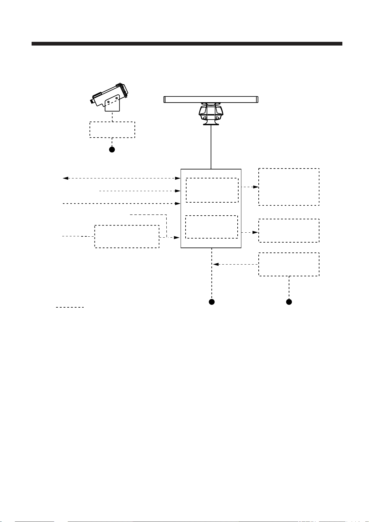
CONFIGURATION OF FR-8051/811 1/8251
Performance Monitor
PM-30
(optional)
Switch Box
115/230 VAC
IEC 1162*
NAV
Video Sounder
IEC 1162*
Log
Fluxgate Heading
Sensor C-2000
Gyro
Gyro Converter
AD-100
*Equivalent to NMEA0183
**12 V/24-32 VDC for FR-8051/8111
24-32 VDC for FR-8251
(In/Out)
(In)
Antenna Unit
15 m standard
Display Unit
RDP-112
Video Plotter
RP-15
Auto Plotter
ARP-15
15 m
Remote Display
FMD-8010
Video Plotter
GD-500
External Alarm
Buzzer OP03-21
Rectifier
RU-1746B-2
Option
12/24-32 VDC** 115/230 VAC
ix
SPECIFICATIONS
Antenna Unit
Type Slotted waveguide array
Polarization Horizontal
Length 4 ft(XN2) 6.5 ft(XN3) 6.5 ft (XN3A) 8 ft(XN4A)
Beamwidth 1.8 x 25° 1.2 x 25° 1.23 x 20° 0.9 x 20°
Rotation speed 24 rpm (36 rpm optional)
Transceiver Module
Frequency 9410 MHz ± 30 MHz (X-band)
Peak output power FR- 8051: 6 kW
FR- 8111: 10 kW
FR- 8251: 25 kW
Transmitting tube FR- 8051: MAF1422B
FR- 8111: MAF1425B
FR- 8251: 9M752 or M5187F
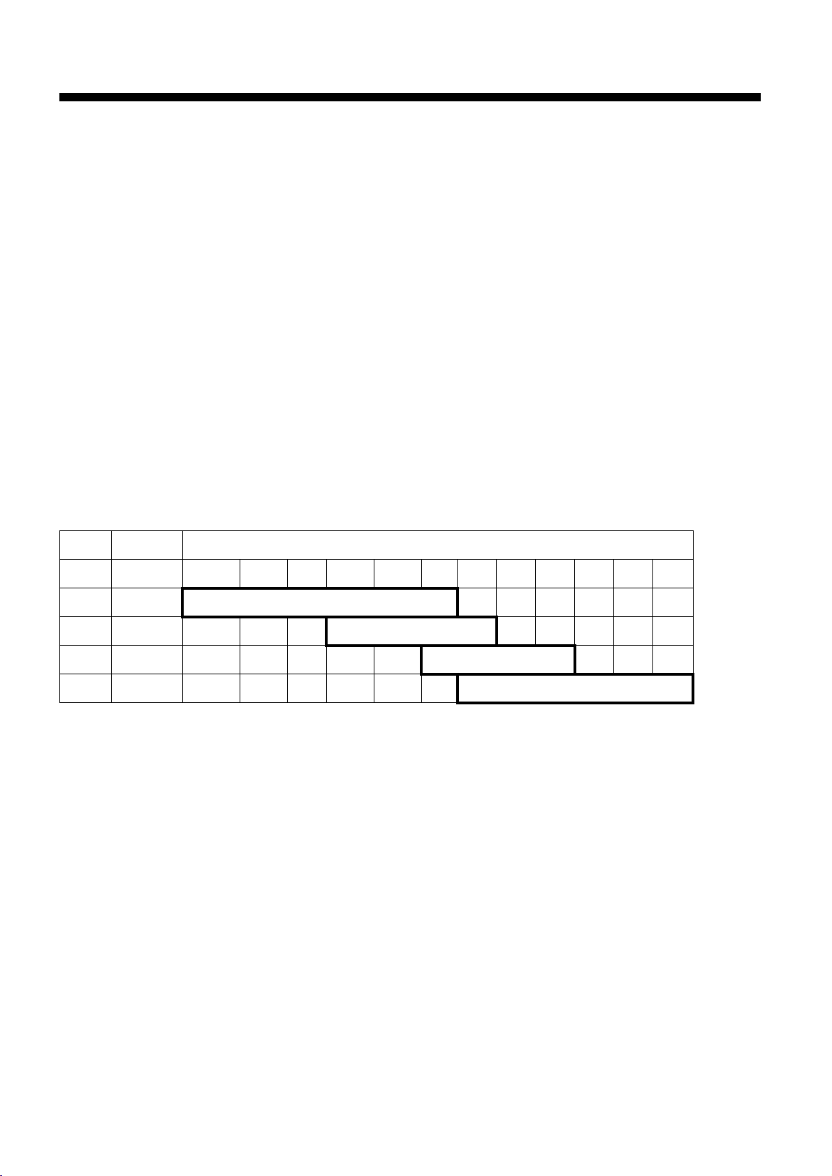
Pulselength (PL) & Pulse Repetition Rate (PRR)
)selimlacituan(egnaR
LPRRP 521.052.05.057.05.1362142842769
PSzH0012sdnocesorcim80.0
1PMzH0012sdnocesorcim3.0
2PMzH0021sdnocesorcim6.0
PL*zH006sdnocesorcim2.1
egnarmn69,27nozH005*
)ylnoPL,2PM,1PM(ffosinoitcejerohceecartdn2nehwzH005
Modulator FR-8051/8111: FET switching method
FR-8251: Line Pulse
I/F amplifier Logarithmic, IF 60 MHz
Bandwidth: 25MHz (0.08 µs), 2.5 MHz (0.3 µs, 0.6 µs, 1.2 µs)
Tuning Automatic or manual
Receiver front end MIC (Microwave IC)
Duplexer Circulator with diode limiter
x

Display Unit
Picture tube 12-inch rectangular green phosphor CRT, 640(H) x 481(V) dots
Effective display diameter 180 mm
Range (nm), Range ring interval (nm), Number of range rings
)mn(egnaR521.052.05.057.05.1362142842769
)mn(lvtnigniR520.050.01.052.052.05.0 1448 2161
sgnirfo.oN 5 5 5 3 36666666
.rettolpoedivhtiwdecafretninehwmn23ro61,8,4,2,1ottesebnaC†
mn69,1528-RF,mn27,1118-RF;mn84,1508-RF:segnarmumixaM*
Minimum range 25 m on 0.25 nm scale
Range discrimination 20 m on 0.75 nm scale
Accuracy Range: 1% of range in use or 8 m, whichever is the greater
Bearing: 1°
Environmental Conditions
Standards IEC 945
Ambient temperature Antenna unit: -25°C to +70°C
Display unit: -15°C to +55°C
Humidity Relative humidity 95% at +40°C
Waterproof test Pressure 3.6 kg/cm2 (antenna unit)
Power Supply and Power Consumption
12 V(FR-8051/8111), 24 V, 32 VDC, or
100 V, 110 V, 115 V, 220 V, 230 VAC, 50/60 Hz, 1ø (rectifier required)
FR-8051, 75 W; FR-8111, 90 W; FR-8251, 130 W
Others
Nav Data Input/Output Input (IEC 1162*) - - GP, LC, or any talker
BWC, DTP, GLL, GLC, HDG, MDA, RMA, RMB, RMC, VTG, DBK,
DBS, DBT, GTD, HDM, HDT, MTW, BWR, VHW, ZDA
AD-100 format heading data
Output (IEC 1162) TLL, RSD, and TTM (w/ARP
*:IEC 1162 is equivalent to NMEA0183, V2.0
Coating color Antenna unit: Munsell N9.5 (white)
Display unit housing: 2.5GY5/1.5 (light gray)
Panel: N3.0 (black)
Compass safe distance Standard compass Steering compass
Display unit (RDP-112): 1.3 m 1.0 m
Antenna unit (C2P7N2N, 6 kW): 3.4 m 2.2 m
(C2P7N2N, 10 kW): 3.8 m 2.4 m
(RSB-0014, 25 kW): 4.3 m 2.5 m
xi

EQUIPMENT LISTS
Standard Set
.oNemaNepyTytQskrameR
1)1508-RF(tinurennacS)3600-BSR(N2N7P2C1 )lanoitpompr63(mpr42
3400-RTR:tinuFR
)1118-RF(tinurennacS)3600-BSR(N2N7P2C)lanoitpompr63(mpr42
4400-RTR:tinuFR
)1528-RF(tinurennacS)4600-BSR(4100-BSR)lanoitpompr63(mpr42
5400-RTR:tinuFR
2tinuyalpsiD*-211-PDR1 ;1118-RF,B;1508-RF,A*
1528-RF,C
3seirosseccA01350-30PFtes1retlifdnadoohgniweiV
4tinuyalpsiD
slairetamnoitallatsni
5tinurennacS
slairetamnoitallatsni
6elbaclangiS†-35-30Stes1m03,52,02(m51:†
yssarotcennocLM20241-30PCenilegatlovhgihroF
7straperapstinuyalpsiD10911-30PStes1
8straperapstinurennacS20111-30PStes1
10151-30PCtes1tinuyalpsidroF
10441-30PCtes1tinuannetnaroF
)lanoitpo
xii

Optional Equipment
.oNemaNepyT.oNedoCskrameR
1elbaclangiS5-55-30S061-554-800m5,rotcennocP5-HX/w
elbacP2-OC
2tinuhctiwsretnI2-JR260-030-000
3tinureifitceR2-B6471-UR934-030-000CAV511
044-030-000CAV032
4elbacrewoPm51C2x8S-VVC436-065-000
5yalpsidroloC041-DC705-000-000
141-DC805-000-000
6yalpsidevalS0108-DMF
7yalpsidetomeR0081-DMF
8rettolpoediV2kraM005/005-DG
9rezzublanretxE12-30PO790-030-000
01revoclyniV1040-430-30756-108-000
11rettolpotuA51-PRA
21rettolpoediV51-PR
31retlifIME00550-30PF099-654-800
41snel/wdooH021-30PO790-030-000
51ecnamrofreP
rotinom
61retrevnocoryG001-DA
03-MP
Spare Parts
.oNemaNepyT.oNedoCytQskrameR
1esuFCAV521A01OBGF560-945-0002V23/V42
2esuFCAV521A02OBGF510-945-0002V21
3rofhsurbnobraC
rotomrennacs
G8D11X6X5-021GM617-136-0002
xiii

CATEGORIZATION BY SPECIFICATION
This series of marine radars are designed to comply with the standards of various national rules and
regulations. Operational convenience is enhanced with the two categories as below although the basic
design approach is the same.
noitcnuFepyt-Repyt-N
mralaenozdrauGmrala"tuO"ro"nI"ylnomrala"nI"
fotinurosruc/MRV
tuodaer
tuodaer
R-type: For fishing boats, pleasure boats, non-Convention cargo ships
N-type: For non-Convention ships in the Netherlands and other countries where the radars must be
approved based on IMO A.477(XII), although not wholly.
gniraebrosruc/LBE
krampihsnwO)todrolobmys(elbaliavA)ylnotod(elbaliavatoN
ms,mk,mnylnomn
elbatceles,evitaler/eurT
edomynani
evitaler:pu-daeH
eurt:MT,UN,UC
xiv

Chapter 1 OPERATION
Control Description
Turns power on.
Press together to turn
power off.
Toggles between
stand-by and transmit.
Presentation mode
Sets up radar for
required objective.
Silences aural
alarms (except guard alarm).
Short press: Offcenter
Long press: Zoom-in
POWER
OFF
ST BY
TX
MODE
FUNCTION
AUDIO
OFF
SHIFT
ZOOM
A/C AUTO (PUSH)
RANGE
GAIN
HM OFF (PUSH)
A/C SEA
A/C RAIN
MARK (PUSH)
BRILL
RINGS (PUSH)
GUARD
ALARM
ECHO
TRAIL
GAIN: Adjusts receiver sensitivity.
Press to erase heading marker;
enable manual tuning of the receiver.
A/C SEA: Suppresses sea clutter.
Press for AUTO Anti-clutter Sea
and Rain.
A/C RAIN: Suppresses rain clutter.
Press to inscribe a reference mark (*).
BRILL: Adjusts display brilliance.
Press to turn range rings on/off
and adjust their brilliance.
Selects radar range.
Sets/cancels guard
alarm zone; silences guard
zone alarm.
Target trails ON/OFF.
Each press processes index lines;
linked with EBL2/VRM2 / fixed / OFF.
Turns an EBL off.
Turns a VRM off.
Registers data on menu;
selects menu item.
Selects plotting
symbol.
EBL
Rotates EBL;
selects items
on menu.
VRM
(
TLL)
Adjusts VRM; outputs
cursor position (TL/L)
to external equipment;
selects items on
menu.
INDEX
LINE
OFF
OFF
ENTER
SELECT
PLOT
SYMBOL
EBL 1/2
VRM 1/2
CURSOR
OFFSET
ON
ON
MENU
CLEAR
DELETE
Each press processes offset EBL;
linked with cursor / fixed / OFF.
Selects EBL to activate.
Selects VRM to activate.
Opens/closes menu.
Clears wrong data; deletes
plot symbols and marks.
TRACKBALL
Shifts cursor and
No.1 EBL origin.
Figure 1-1 Control description
1–1

Display Indications
Range ring interval
Range
ZOOM (or SHIFT)
Pulselength
Presentation mode
Heading marker
Guard zone
area
No.1 EBL
No.1 VRM
Heading (gyro or
magnetic)
0.25
0.05
ZOOM
SP
HU
NM
HDG 123.4°
Speed
(MANUAL, LOG or NAV)
SPEED
MANUAL 30.0kt
AUTO
TRU TRAIL
00:45
30M
GUARD1
GUARD2
IN
Tuning indicator,
AUTO (or MANU) tuning
Echo trail (TRU/REL)
Elapsed time, trail interval
Guard zone 1 (active alarm
is circumscribed)
Guard zone 2
IN (guard zone type), SET
(set alarm), or
ACK (alarm temporarily
deactivated)
No.2 EBL
Waypoint marker
Range rings
Cursor
Auto clutter suppression
Function in use
(F3, Long range
Echo Stretch)
No.1 EBL bearing
(readout of active EBL
is circumscribed)
No.2 EBL bearing
A/C
F3
L-ES
345.6°R
23.0°R
29:59
Watch alarm
elapsed time
EBL
+
105.0°R 00.74nm
Cursor
bearing
Cursor
range
VRM
TTG
12:34
Figure 1-2 Display indications
NR
IR2
ES1
EAV1
0.080nm
0.220nm
No.2 VRM
Noise Rejection
Interference Rejection
Echo Stretch
Echo Averaging
No.1 VRM range
(readout of active VRM is
circumscribed)
No.2 VRM range
Time-to-go
1–2

A/C
F3
L-ES
18.0°T
290.0°R
99:99
TIME
EBL
TRUE VECTOR
30MIN
01:28
93.7°R 13.82nm
332.7°T
BRG
12.5nm
RNG
8.89nm
CPA
VRM
TTG
COURSE
SPEED
TCPA
NR
IR2
ES3
EAV1
1.829nm
10.87nm
12:34
198.5°T
92.8kt
05:11
Normal + PLOT
Select PLOT on
DISP DATA menu.
PLOT Data
Normal + NAV
Select NAV on
DISP DATA menu.
.
A/C
F3
L-ES
18.0°T
EBL
290.0°R
34°
OWN
39.46N
SHIP
135°
23.08E
COURSE
216.1°
DATE APR. 08 20:31
99:99
A/C
F3
L-ES
18.0°T
290.0°R
34°
OWN
39.46N
SHIP
135°
23.08E
COURSE
216.1°
DATE APR. 08 20:31
EBL
99:99
TRUE VECTOR
30MIN
TIME
01:28
(GPS)
(GPS)
93.7°R
13.82nm
34
°39.46N
135
°23.08E
TTG
12:35
93.7°R
13.82nm
34
°39.46N
135
°23.08E
TTG
12:35
BRG
332.7°T
RNG
12.5nm
CPA
8.89nm
VRM
WAY
POINT
TTG
DEPTH
TEMP
VRM
WAY
POINT
TTG
DEPTH
TEMP
COURSE
SPEED
TCPA
NR
IR2
ES3
EAV1
1.829nm
10.87nm
321.6°
18.23nm
35:42
265.2m
23.5°C
NR
IR2
ES3
EAV1
1.829nm
10.87nm
321.6°
18.23nm
35:42
265.2m
23.5°C
198.5°T
92.8kt
05:11
NAV Data
(Requires position,
depth and water
temperature data.)
NORMAL + NAV + PLOT
Select ALL on DISP
DATA menu.
NAV Data
PLOT Data
Figure 1-3 Display indications (lower part)
1–3

1.1 Turning the Radar On/Off
DANGER
1.3 Selecting Range
The range selected automatically determines the
range ring interval, the number of range rings and
pulse repetition rate, for optimal detection capability in short to long ranges.
Before turning on the radar, make
sure no one is near the antenna unit.
Serious injury or death can result if
a rotating antenna strikes someone
standing nearby.
Turning on the radar
Press the POWER key. The control panel lights
and a timer displays the time remaining for warm
up of the magnetron, counting down from 3:00
to 0:00.
Turning off the radar
Press POWER and ST BY/TX keys together.
1.2 Transmitting, Stand-by
Range
Range
Range ring
interval
Pulselength
0.75NM
0.25
SP
Range
rings
Figure 1-4 Location of range, range ring
interval and pulselength indications
Procedure
Press the RANGE key at + or –. The range, range
ring interval and pulselength appear at the top
left corner of the display.
Transmitting
After the power is turned on and the magnetron
has warmed up, ST-BY (Stand-By) appears at the
screen center, indicating the radar is ready to
transmit radar pulses. In stand-by the radar is
available for use at any time.
Press the ST BY/TX key to transmit. The radar
displays echoes in eight intensities according to
echo strength.
Stand-by
When you won’t be using the radar for an extended period, but you want to keep it in a state
of readiness, place it in stand-by by pressing the
ST BY/TX key. The display shows ST-BY.
1–4

1.4 Presentation Mode
This radar has the following presentation modes:
Relative Motion (RM)
Head-up: Unstabilized
Course-up: Compass-stabilized relative to
ship’s intended course
North-up: Compass-stabilized with
reference to north
True Motion (TM)
North-up: Ground or sea stabilized with
compass and speed inputs
Selecting presentation mode
Each time the MODE key is pressed, the presentation mode and mode indication at the upperleft corner of the screen change cyclically.
Loss of gyro signal
When the gyro signal is lost, the presentation
mode automatically becomes Head-up and
the HDG readout at the screen top shows
xxx.x. The x's do not disappear even when the
gyro signal is restored, to warn the operator
that the readout may be unreliable.
Match the gyro readout with the gyrocompass
reading. Press the MODE key.
Presentation mode,
representative display
350
320
220
320
220
210
330
330
210
340
200
200
340
190
350
190
H
A
D
U
C
O
U
R
E
U
E
310
300
290
280
P
270
260
250
240
230
310
300
290
S
280
270
260
P
250
240
230
000
180
000
180
170
010
010
170
020
160
020
160
030
150
030
150
040
140
140
040
130
050
050
130
120
060
120
060
070
110
070
110
080
100
080
100
090
Description
A display withouth azimuth stabilization in which the
line connecting the center with the top of the display
indicates own ship's heading.
The target pips are painted at their measured distances
and in their directions relative to own ship's heading.
090
The short dashed line on the bearing scale is the north
mark and it indicates compass north.
Failure of the gyro will remove the north marker and
the HDG indication shows "xxx.x".
An azimuth stabilized display in which a line connecting the center with the top of the display indicates
own ship's intended course (namely, own ship's
previous heading just before this mode has been
selected).
Target pips are painted at their measured distances
and in their directions relative to the intended course
which is maintained at the 0-degree position while the
heading marker moves in accordance with the ship's
yawing and course changes. This mode is useful to
avoid smearing of picture during course changes. After
a course change, press the SHIFT ZOOM key to reset
the picture orientation if you wish to continue using
the Course-up mode.
If the gyrocompass fails, the presentation mode changes
to the Head-up mode and the north marker disappears.
Also, the HDG readout at the screen top shows xxx.x.
1–5
 Loading...