

Page 1

OPERATOR'S MANUAL
INMARSAT MINI-C
MOBILE EARTH STATION
MODEL
FELCOM 16
www.furuno.co.jp
Page 2

Thepaperusedinthismanual
9‑52Ashihara‑cho,
Fax:
A:MAY
2003
F1:OCT.15,2008
Pub.No.
(
)
*
00080934515
**00080934515
*
Nishinomiya,662‑8580,JAPAN
Telephone: +81‑(0)798‑65‑2111
+81‑(0)798‑65‑4200
iselementalchlorinefree.
・FURUNOAuthorizedDistributor/Dealer
Allrightsreserved.
DAMI
FELCOM16
PrintedinJapan
OME‑56380‑F1
*00080934515**00080934515*
*00080934515*
Page 3
IMPORTANT NOTICES
General
• Do not copy any part of this manual without written permission.
• If this manual is lost or worn, contact your dealer about replacement.
• The contents of this manual and equipment specifications can change without notice.
• The example screens (or illustrations) shown in t his manual can be different from the
screens you see on your display. The screen you see depends on your system
configuration and equipm ent settings.
• Save this manual for future reference.
• The wrong use or modification of the equipment (including software) by persons not
authorized by FURUNO will cancel the warranty
How to discard this product
Discard this product according to local regulations for the disposal of industrial waste. For
disposal in the USA, see the homepage of the Elect ronics Industries Alliance
(http://www.eiae.org/) for the correct method of disposal.
How to discard a used battery
In the European Union
The crossed-out trash can symbol indicates that all t ypes of
batteries must not be discarded in standard t r ash, or at a trash
site. Take the used batteries to a battery collection sit e
according to your national legislation a nd the Batteries Directive
2006/66/EU.
In the USA
The Mobius loop symbol (three chasing arrows) indicates that
Ni-Cd and lead-acid rechargeable batteries must be recycled.
Take the used batteries to a battery collection site according to
local laws.
In the other countries
There are no international standards f or t he battery recycle symbol. The number of symbols
can increase when the other countries make th eir own recycling symbols in the future.
Ni-Cd Pb
Cd
i
Page 4
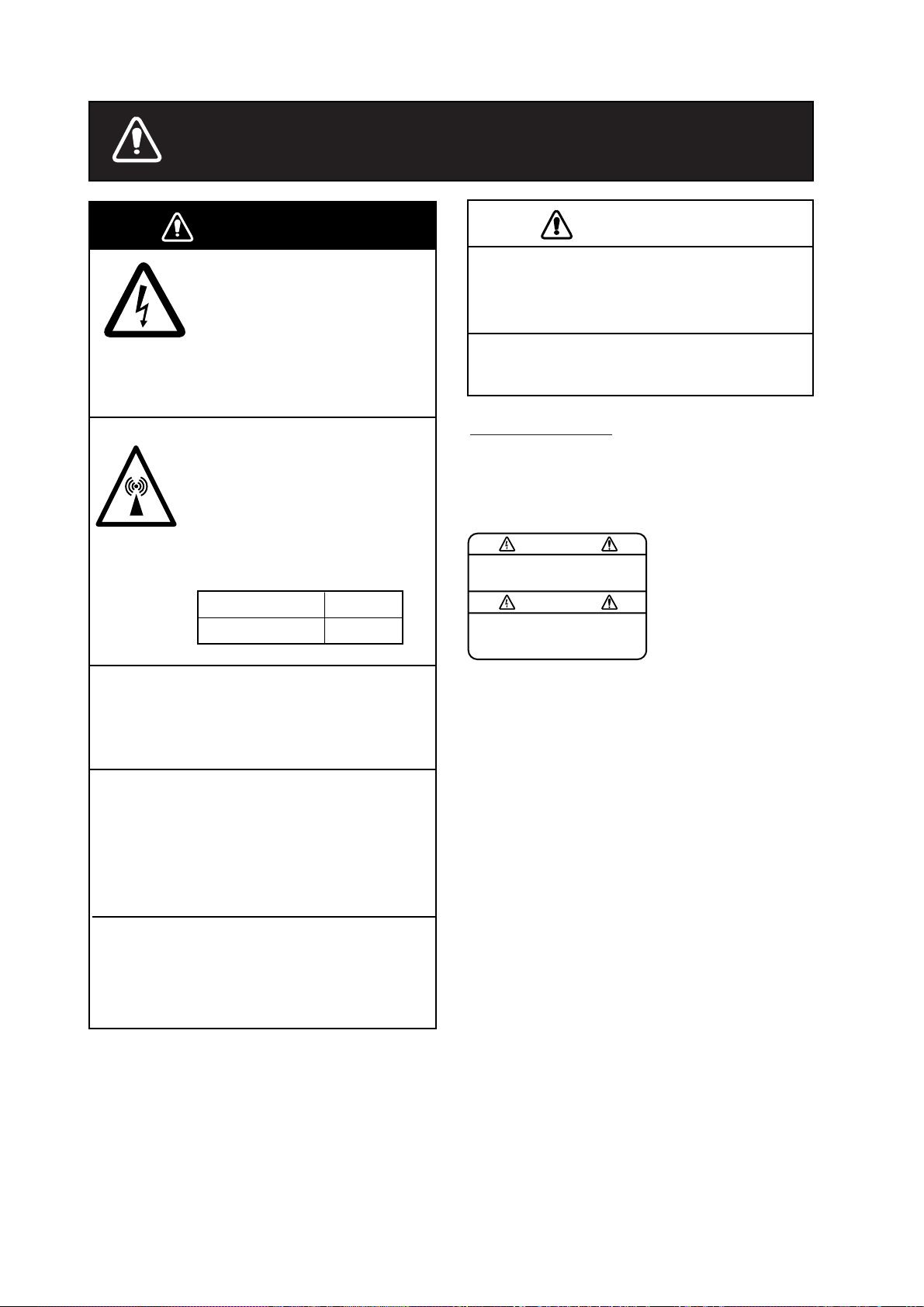
SAFETY INSTRUCTIONS
WARNING
Do not open the equipment.
Hazardous voltage which can
cause electrical shock, burn
or serious injury exists inside
the equipment. Only qualified
personnel should work inside
the equipment.
Hazardous microwave.
Do not approach within
60 cm of the antenna radome
when it is transmitting.
Microwave radiation can be
harmful to the human body,
particularey the eyes.
Radiation Level At
10W/m
2
60 cm
CAUTION
Use the proper fuse.
Use of a wrong fuse can result in fire or
permanent damage to the equipment.
This equipment is intended for marine
application.
WARNING LABEL
A warning label is attached to the
communication unit. Do not remove the
label. If the label is missing or damaged,
contact your dealer about replacement.
WARNING
To avoid electrical shock, do not
remove cover. No user-serviceable
parts inside.
Name: Warning Label (1)
Type: 86-003-1011-1
Code No.: 100-236-231
Do not disassemble or modify the
equipment.
Fire, electrical shock or serious injury can
result.
Turn off the power immediately at the
ship's mains switchboard if water
leaks into the equipment or the equipment is emitting smoke or fire.
Continued use of the equipment can cause
fire or electrical shock.
Any repair work must be done by a
licensed radio technician.
Improper repair work can cause electrical
shock or fire.
ii
Page 5

TABLE OF CONTENTS
FOREWORD ....................................................................................................... vii
SYSTEM CONFIGURATION ................................................................................ ix
INMARSAT C SYSTEM OVERVIEW .................................................................... x
LRIT COMPLIANCE.......................................................................................... xvii
1. OPERATIONAL OVERVIEW ......................................................................... 1-1
1.1 Communication Unit .................................................................................................. 1-1
1.1.1 Turning the power on/off. ................................................................................. 1-1
1.1.2 Diagnostics ..................................................................................................... 1-1
1.2 Terminal Unit (PC) Operation ..................................................................................... 1-2
1.2.1 Starting, quitting the application ....................................................................... 1-2
1.2.2 Controls description ......................................................................................... 1-3
1.2.3 Shortcut keys .................................................................................................. 1-4
1.2.4 Function keys .................................................................................................. 1-5
1.3 Standby Display ......................................................................................................... 1-6
1.3.1 Display indications........................................................................................... 1-7
1.4 Menu Overview ........................................................................................................ 1-1 1
1.5 Error Messages and Alerts ....................................................................................... 1-12
1.6 Choosing a Printer ................................................................................................... 1-13
2. SYSTEM INITIALIZATION ............................................................................ 2-1
2.1 System Settings ......................................................................................................... 2-1
2.2 PC Window Setup...................................................................................................... 2-3
2.3 Login and Logout ....................................................................................................... 2-5
2.3.1 Login ............................................................................................................... 2-5
2.3.2 Logout ............................................................................................................. 2-7
2.4 EGC Settings ............................................................................................................. 2-8
2.4.1 What is the EGC (Enhanced Group Call) service? .......................................... 2-8
2.4.2 EGC setup .................................................................................................... 2-10
2.4.3 Adding EGC channels ................................................................................... 2-13
2.4.4 Saving, printing EGC messages automatically .............................................. 2-15
2.5 Adding NCS Channels ............................................................................................. 2-17
2.6 LES List ................................................................................................................... 2-19
2.6.1 Setting toll charges ........................................................................................ 2-19
2.6.2 Registering LES to LES list ........................................................................... 2-21
2.6.3 Editing the LES list. ....................................................................................... 2-22
2.6.4 Printing the LES list ....................................................................................... 2-23
2.7 Station List ............................................................................................................... 2-24
2.7.1 Adding stations to the station list ................................................................... 2-24
2.7.2 Editing the station list .................................................................................... 2-28
2.7.3 Printing the station list ................................................................................... 2-29
2.8 Entering Own Ship’s Position ................................................................................... 2-30
2.9 Creating A Directory ................................................................................................. 2-31
2.9.1 Creating a directory where to store messages ............................................... 2-31
2.9.2 Specifying directory where to store messages ............................................... 2-33
iii
Page 6

TABLE OF CONTENTS
2.10 E-mail Service/SMS Station List.................................................................................2-34
2.11 E-mail Setup...............................................................................................................2-37
2.12 Saving, Loading System Settings ..............................................................................2-38
2.12.1 Saving system settings to a floppy disk...........................................................2-38
2.12.2 Loading system settings to the terminal unit ...................................................2-38
3. FILE OPERATIONS....................................................................................... 3-1
3.1 Files and Working Areas..............................................................................................3-1
3.2 Preparing Files.............................................................................................................3-2
3.2.1 Preparing a routine file ......................................................................................3-2
3.2.2 Preparing a confidential file...............................................................................3-3
3.2.3 Editor menu setup .............................................................................................3-4
3.2.4 Working with text...............................................................................................3-5
3.3 Saving Files................................................................................................................3-10
3.3.1 Save file, retain place on screen .....................................................................3-10
3.3.2 Save file, clear screen.....................................................................................3-11
3.4 Opening Files.............................................................................................................3-12
3.4.1 Opening files ...................................................................................................3-12
3.4.2 Switching between files...................................................................................3-12
3.4.3 Opening a file when both working areas are occupied....................................3-13
3.5 Saving a File Under a New Name..............................................................................3-14
3.6 Printing Files ..............................................................................................................3-15
3.7 Combining Files .........................................................................................................3-16
3.8 Deleting Files .............................................................................................................3-17
3.9 Renaming Files..........................................................................................................3-18
3.10 Decoding E-mail Attachment ......................................................................................3-19
4. INMARSAT C COMMUNICATIONS..............................................................4-1
4.1 Transmitting .................................................................................................................4-1
4.1.1 Code description ...............................................................................................4-1
4.1.2 Transmitting prepared message........................................................................4-2
4.1.3 Transmitting a file stored on the hard disk.......................................................4-15
4.1.4 Canceling transmission on a message awaiting transmission ........................4-16
4.1.5 Requesting delivery status ..............................................................................4-17
4.1.6 Accessing the code number services..............................................................4-20
4.1.7 Displaying the send message log....................................................................4-22
4.2 Receiving ...................................................................................................................4-23
4.2.1 When a message is received .......................................................................... 4-23
4.2.2 Setting the receive alarm.................................................................................4-24
4.2.3 Displaying, printing received messages..........................................................4.24
4.2.4 Automatically printing received messages ......................................................4-28
4.2.5 Saving received messages to the hard disk....................................................4-28
4.2.6 Automatically saving received messages to the hard disk..............................4-29
4.2.7 Deleting received messages ...........................................................................4-30
4.3 Display Log ................................................................................................................4-31
4.3.1 Displaying and printing the display log............................................................4-31
4.3.2 Automatic printing of display log......................................................................4-32
iv
Page 7

TABLE OF CONTENTS
4.4 EGC Messages........................................................................................................4-33
4.4.1 Displaying and reprinting EGC messages.....................................................4-33
4.4.2 Displaying EGC closed network ID (ENID)....................................................4-34
4.4.3 Displaying the EGC message log..................................................................4-35
5. DATA REPORTING AND POLLING..............................................................5-1
5.1 Data Reporting...........................................................................................................5-1
5.1.1 Setting a data report........................................................................................5-2
5.1.2 Setting a message report ................................................................................5-4
5-1.3 Automatic printing of data report, polling command.........................................5-7
5.2 Polling........................................................................................................................5-8
5.2.1 Polling commands...........................................................................................5-8
5.2.2 Other polling commands ................................................................................5-10
5.2.3 Polling reception............................................................................................ 5-11
5.3 DNID (Data Network Identification)..........................................................................5-12
5.3.1 Displaying DNID............................................................................................5-12
5.3.2 Enabling/Disabling DNID ...............................................................................5-13
6. OTHER FUNCTIONS .................................................................................... 6-1
6.1 Aborting an Operation................................................................................................6-1
6.2 Scanning NCS Common Channel..............................................................................6-2
6.3 Choosing EGC Receiving Channel............................................................................6-3
6.4 Choosing NCS Channel.............................................................................................6-4
6.5 LES Information.........................................................................................................6-5
7. MAINTENANCE, TROUBLESHOOTING......................................................7-1
7.1 General Checking and Maintenance..........................................................................7-1
7.2 Diagnostics................................................................................................................7-2
7.2.1 Self test at power on........................................................................................7-2
7.2.2 Testing the communication unit through the keyboard, displaying program
version no........................................................................................................7-2
7.3 Performance Verification (PV) Test. ...........................................................................7-4
7.3.1 PV test sequence............................................................................................7-4
7.3.2 PV test procedure............................................................................................7-5
7.3.3 Results of PV test............................................................................................7-6
7.4 System Status Monitor...............................................................................................7-7
7.5 Replacing the Fuse....................................................................................................7-8
7.6 Error Messages.........................................................................................................7-9
7.6.1 Equipment trouble messages..........................................................................7-9
7.6.2 Warning messages........................................................................................7-10
v
Page 8

TABLE OF CONTENTS
APPENDIX ......................................................................................................AP-1
Menu Tree.......................................................................................................................AP-1
Internati on al Telex/Telephon e Country Code List.............................................................AP-8
LES List......................................................................................................................... AP-15
International Telex Abbreviations...................................................................................AP-16
Internat ional Telegraphy Alp habet..................................................................................AP-17
Messages......................................................................................................................AP-18
Parts List .......................................................................................................................AP-21
Parts Location ...............................................................................................................AP-22
SPECIFICATIONS...........................................................................................SP-1
INDEX............................................................................................................... IN-1
vi
Page 9

FOREWORD
Introduction
FURUNO Electric Company thanks you for considering and purchasing the
FELCOM 16 Inmarsat Mini-C Mobile Earth Station. We are confident you will
discover why the FURUNO name has become synonymous with quality and
reliability.
The FELCOM 16 mainly consists of a communication unit and a n antenna unit.
Connected to a PC (local supply), the FE LCOM 16 provides a wide range of
communication services, such as e-m ail and telex, for mobile and fixed terrestrial
subscribers in the Inmarsat C communication network. Its compact size permits
installation where space is limited.
FURUNO designs and manufactures this equipment with much attention to
operation and maintenance simplicity. However, please read and follow the
recommended procedures for operation and maintenance to get the most out of
the equipment.
This manual provides a brief introduct ion to the Inmarsat C system (pages x thru
xv). For more detailed information, refer to the inf ormation below.
Inmarsat C Maritime Customer Relations Officer
Maritime Services Operations Department
International Maritime Satellite Or ganization (Inmarsat)
Address: 99 City Road, London, EC1Y 1AX, UK
Telephone: +44 20 7728 1777 (Switchboard)
Fax: +44 20 7728 1142
URL: www.inmarsat.com
E-mail customer_care@inmarsat.com
vii
Page 10

FOREWORD
Features
• E-mail facility. (To transmit E-mail, r egister with an LES provide r which
provides e-mail services. E - m ail charges are calculated separately.)
• Built -i n E nhanced Group Call ( E G C) r ec eiver. May be set to operate as
EGC-only receiver .
• St or e- and-forward t elex communicati on ( public telex network)
• Data report ing and Polling
• Diagnosti c programs for maintenance
• Menu driven o peration
• VMS (Vessel Monitoring System) applicable
Program Number
PC Board Program No. Version No. Date of Modification
TERMINAL 1650166 03 5/2004
RF CON CPU 1650160 03 5/2004
viii
Page 11
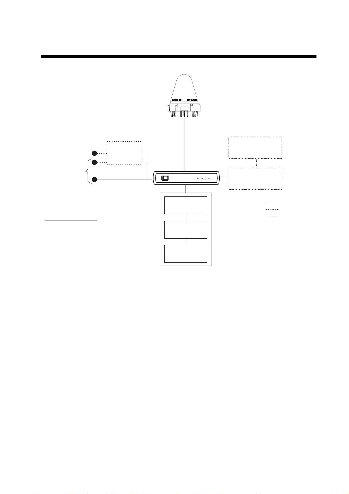
SYSTEM CONFIGURATION
ANTENNA
UNIT
IC-116
SHIP'S MAINS
100-115/200-230 V AC
1φ, 50/60 Hz
SHIP'S MAINS
12-24 VDC
COMMUNICATION UNIT IC-216
(with internal GPS receiver)
CATEGORY OF UNITS
Antenna Unit: Exposed to Weather
Communication Unit: Protected from Weather
Other Units: Protected from Weather
AC-DC
Power Supply
PR-240
INMARSAT MINI-C MOBILE EARTH STATION
FURUNO
POWER
I
O
JUNCTION BOX
IC-315
SSAS ALERT UNIT
IC-307
LOGIN
POWER
TX
ERROR
(PC/AT compatible)
*
PRINTER
PERSONAL
COMPUTER
: Standard
: Option
: Local Supply
* : SSAS Specification
SSAS ALERT UNIT
IC-307
ix
Page 12

INMARSAT C SYSTEM OVERVIEW
Introduction
The Inmar s at C s ystem provides worldwide telex and data transmission and
reception of written informat ion to owners of an Inmar s at C transceiver or a
terrestrial telex network vi a s atellite. Further, e-mai l may be sent via the int er net.
Communic ation mode is store-and-forward t elex, which means all information
sent are fi rs t stored at an LES and then delivered to designated party.
An EGC (Enha nc ed Group Call) receiver is built in t he FELCOM 16 to receive
the following types of messages, br oadcast by LESs:
• SafetyNET
distribute maritime safety information to ships within selected areas.
• FleetNET
can use this service to transmi t trade information (for example, company
news or m ar ket prices) simultaneously to a selec ted group of ships , to
provide up-to- the-minute information.
• EGC system-related is sent by Inmarsat to cert ain shipping companies and
geographical areas.
Besides i ts primary appl ication of ship-shore, s hor e- s hip or ship-ship
communications, the Inmars at C service has also proved beneficial to trucking
firms who have found it indispensable for communi cating with thei r vehi c les. In
this manual, however, we will concentr ate on ship appli cations, the main
application.
TM
-governments and maritim e authorities can use t his service to
TM
-commercial s ubs c r iption organizations or shipping companies
x
Page 13
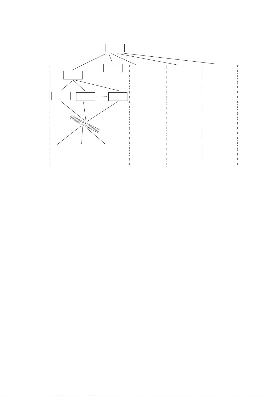
Inmarsat C System Configuration
OCC
SCC
NCS
INMARSAT C SYST EM
LES
LES LES
Satellite
-/+: To set option
0.0 m
-/+: To set option
0.0 m
-/+: To set option
AOR-West AOR-East IOR POR
OCC: Operation Control Center
SCC:
Satellite Control Center
NCS:
Network Coordination Station
MES:
Mobile Earth Station
LES:
Land Earth Station
Same as left Same as left Same as left
MES
0.0 m
Inmarsat C system configuration
xi
Page 14

INMARSAT C SYST EM
The Inmar s at C s ystem consist s of the Operation Control Center (OCC), Satellite
Control Centers (SCC), Network Coordination Stations (NCS) , Land Earth
Stations (LES) and Mobile Earth Stations (MES). The OCC, located at Inmarsat’s
London head quar ters, coordinat es a wide range of ac tivities in the I nm ar s at
system , inc luding commissioning of mobile earth stations.
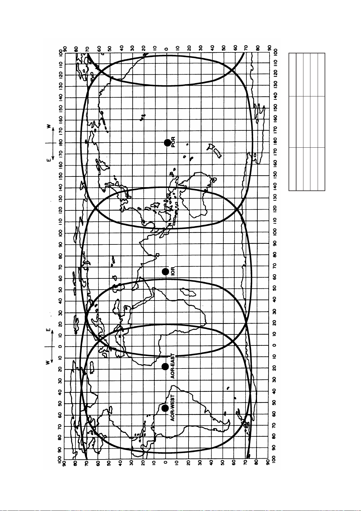
The Inmar s at C s ystem divides the world into four regions and each region is
covered by its own satellite.
Inmarsat system satellites
Region Satellite Satellite Position
AOR-West Inmarsat 3, F4 54.0°W
AOR-East Inmarsat 3, F2 15.5°W
IOR Inmarsat 3, F1 64.0°E
POR Inmarsat 3, F3 178.0°E
In each region there is one NCS and several LESs. The NCS keeps track of all
Inmarsat C transceivers in its region and broadcasts inf or m ation such as
navigati onal warnings, w eather reports and news. The LESs provide the link
between the MES and the terrestrial telecommunications network s vi a s at ellite.
xii
Page 15
INMARSAT C SYST EM
178°E
64.0°E
15.5°W
INMARSAT-3, F1
INMARSAT-3, F2
IOR
AOR-EAST
54.0°W
INMARSAT-3, F4
AOR-WEST
POSITION
INMARSAT-3, F3
SATELLITE NAME
POR
AREA
Coverage area of Inmarsat satellites
xiii
Page 16
INMARSAT C SYST EM
v
Communications Network
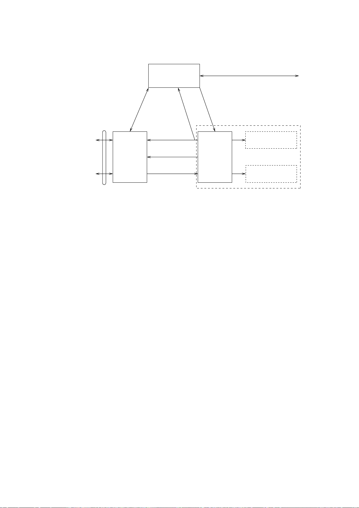
The illus tration below shows the Inmarsat C communications network.
Data
Communications
Network
Telex Network
Terrestrial
Communications
Network
NCS common channel The NCS has two major functions:
1) Transmitting information on a common channel.
2) Transmitting EGC messages to MESs.
NCS/LES signaling link This i s the link between NCS and all LE S s in its
LES TDM channel This channel carries the circ uit control signal for
MES message channel This channel carries messages from MES to LES.
MES signaling channel This channel transmits request s , data reports, et c . In
NCS/NCS signaling link This i s the link between NCSs. I t exchanges data
MES interface The MES c ons ists of the Dat a Circuit Terminating
Terrestrial network The major functions of the LESs are:
interface
1) Telex store-and-forward conversion
2) Handling EGC messages
3) Data Rep or ting and Polling
4) Distress m es s age processing
NCS/LES
Signaling Link
Land Earth
Station
(LES)
Network
Coordination
Station (NCS)
MES Signaling
Channel
MES Message
Channel
LES TDM
Channel
NCS/NCS Signaling Link
NCS Common Channel
Data Circuit
Terminating
Equipment
(DCE)
Equipment (DTE)
Enhanced Group
Calling (EGC) Receiver
Mobile Earth
Station (MES)
Data Terminal
Inmarsat C communications network
region. All EGC messages pass through this l ink.
MES and tr ans m its messages from LE S to MES.
addition, it carries login and logout from ME S to
NCS.
between MESs operating i n different ocean regions.
Equipment (DCE) and the Data Terminal Equipment
(DTE). The DCE consists of the antenna unit , and
the DTE c ons ists of the communi c ations unit and
terminal unit (PC).
xi
Page 17

v
Types of MES
There are t hr ee t ypes of MES: class 1, class 2 and class 3. This FELCOM 16
is a class 2 MES.
Class 1: 1) Transmits m es s ages to LES
2) Receives messages from LES
Class 2: 1) The functions of class 1 plus operation as an EGC receive r
2) EGC-only receiver
Class 3: The function of cl as s 1 plus simultaneous operation as an
INMARSAT C SYST EM
when not transmitting or r ec eiving.
EGC-only receiver .
x
Page 18

INMARSAT C SYST EM
This p age is intentionally left blank.
xvi
Page 19

LRIT COMPLIANCE
This equipment can function as a marine communications t erminal for the LRIT
(Long-Range Identification and Tracking) system, as prescribed by the IMO regulation
MSC.202(81). The LRIT uses the F E LCOM's Data Report/Polling feature f or LRIT position
reporting.
The LRIT system is fully automatic, thus no operation is required of the user. However,
follow the guidelines shown below to use this equipment as an LRIT device.
The data listed below is sent by the FELCO M when it receives a command from the LRIT
data center.
• ID number of this equipment
• Position of your ship
• Time of position
The FELCOM sends data at intervals between 15 minutes and 6 hours.
The FELCOM automatically receives commands (related to time of position reporting,
transmission interval) from the LRIT dat a center. To receive the commands at all times,
keep the equipment powered and l ogged in.
Satellite System
Coast Station
Country A
LRIT DATA
CENTER
Country B
Country C
LRIT system
xvii
Page 20

LRIT COMPLIANCE
Notes on the LRIT system
• Power the equipment and keep it logged in at all times except for special occasions
such as when the ship is dry-docked for repairs. Position information is automatically
sent at fixed intervals, thus no operati on is required. However, keep the equipment in a
ready state to received commands from the LRIT data center. Combined use for routine
messages, distress messages and SSAS (Ship Security Alert System) is possible.
• The source of position data for this equipment is its internal GPS receiver thus no
external receiver is necessary.
• This equipment must be powered in the following manner.
- Conn the equipment to both main and emergency power sources (via AC-DC po wer
unit PR-240).
• If an error message appears, take the necessary measures to restore normal operation
as soon as possible. Shown below are representative alarms.
- WARNING: External NAV equipment failure.
Posit ion data is not correctly input from the external GNSS equipment. Check the
G NSS equipment and the wiring between it and the FELCOM.
- WARNING: Internal GPS UNIT failure.
Posit ion data is not correctly input from the internal GPS receiver. If this alarm occurs
f r equently, have the set checked.
- WARNING: Synchronization loss. Please check the current Oc ean Region. -
- WARNING: BBER over 80%. Scanning NCS start manually.
Problem with receiving the Inmarsat-C signal. Check if t he current sea area is
suitable for your position. If it is not, change the sea area. If the area is suitable and
t he alarm continues, check the antenna and ant enna cable. Request service if the
problem persists.
xviii
Page 21
1. OPERATIONAL OVERVIEW
1.1 Communication Unit
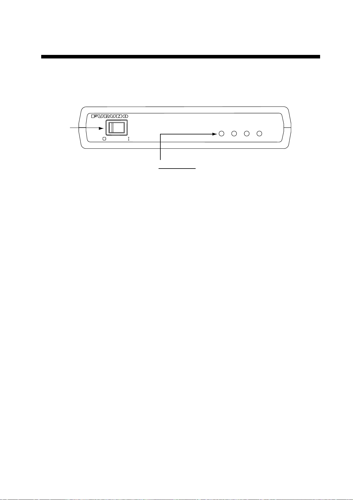
The communication unit is the heart of the FELCOM 16 system, transm itting and
receiving messages via the I nm ars at system.
INMARSAT MINI-C MOBILE EARTH STATION
POWER
Switch
POWER
Status LEDs
POWER: Lights (in green) when power is on.
LOGIN: Lights (in green) when logged in;
TX: Lights (in green) when transmitting.
ERROR: Flashes (in red) for equipment error.
Communication unit IC-216
1.1.1 Turning the power on/off
Press the [P OWER] switch to power the communication unit and antenna on or
off.
Note: The example screens s hown in this m anual may not match the screens
you see on y our display. The scr een you see depends on your system
configurat ion and equipment s ettings.
1.1.2 Diagnostics
POWER
flashes (in green) in green in other instances.
ERROR
TX
LOGIN
When the communication unit is turned on it automati c ally conducts a ser ies of
diagnosti c t es ts to check it s elf for proper operati on. The test t ak es about 30
seconds and al l lamps are on duri ng the test. For furt her details, s ee Chapt er 7.
1-1
Page 22

1. OPERATIONAL OVERVIEW
1.2 Terminal Unit (PC) Operation
All operations are carried out from the terminal unit (local supply), through an
easy-to-follow menu system. In this manual the PC is referred to as “Terminal
Unit.” Note that it is necessary to supply a printer.
PC requirements
• Operating system: Windows98, Windows 2000, Windows ME,
XP, or Vista
• Memory: At least 32 MB
• Free space in hard disk: At least 20 MB
• CPU: Pentium 100 MHz or higher
• Floppy disk drive
Windows is a registered trademark of Microsof t Corporation in the US and other
countries used under license.
1.2.1 Starting, quitting the application
For information about terminal unit operation see the PC’s owner’s manual.
1. Turn on the communications unit.
2. Turn on the terminal unit.
3. Double-click the F16PC icon to start the application. Af ter the program has
been loaded the standby display appears. For details about the standby
display see paragraph 1.3.
F16PC icon
Note: The example screens shown in this manual may not match the
screens you see on your display. The screen you see depends on your
system configuration and equipment settings.
4. To quit the application, press the [F12] key while pressing the [Alt] key. The
following display appears. (You may also quit the application by clicking the
Close button at the top right corner of the screen.)
OK to quit system?
1-2
Yes No
5. Press the [←] key to choose Y es and then press the [Enter] key.
6. Turn off the terminal unit in accordance to Windows operating procedure.
7. Turn off the communications unit.
Note: If a different method is used to quit the application, any settin gs changed
before quitting will not be saved.
Page 23

1.2.2 Controls description
The FELCOM 16 is almost 100% key board controlled. Operation is c ar r ied out
with the f unction keys, numbered F1-F10 at the top of the terminal unit ’s
keyboard.
Controls
Esc Cancels k ey input and returns to pre vi ous display s cr een.
F1-F10 These are t he function keys. They choose menus.
Backspace Deletes the char ac ter to the left of the cursor.
Insert Works the same as “paste.” See “ Copying and pasting text” in
Delete Deletes the c haracter selected with the cursor.
Home Moves the cursor to the t op of the message being edi ted.
End Moves the cursor to the bottom of t he m es s age being edited.
PgUp Goes to the previous page of the edit screen.
paragraph 3.2.4.
1. OPERATIONAL OVERVIEW
PgDn Goes to the next page of the edit screen.
[↑], [↓], [←], [→] Control the cursor.
Enter Registers key input .
Shift Chooses upper or lower case alphabet. Pr es s and hold down
the key and t hen pr ess the [Caps Lock] to get upper or lower
case alphabet. Note that only upper case alphabet ar e us ed in
telex.
Alt Executes the shortcut key operation when combined with an
alphabet k ey. See paragra ph 1.2.3.
Sp ace Bar Inserts a space. In addition, it display s the f ile list, a parti al
view of a fil e, etc., depending on menu.
Caps Lock Turns upper case alphabet input on or off. The Caps Lock LED
lights when upper case input is on.
Tab Inserts horizontal tab characters. The number of t ab c har ac ters
the key can insert per line of text can be programmed for two,
four or eight tabs.
1-3
Page 24

1. OPERATIONAL OVERVIEW
Ctrl Works in combination with alphabet keys as follows:
Ctrl + [M]: Same as Enter.
Ctrl + [H]: Same As Back Space.
Ctrl + [I]: Same as Insert.
Ctrl + [V]: Same as Overwrite+Insert.
Num Lock Turns numeric input on or off . Note that you cannot enter
alphabet when the Num LED is lit.
Note: In telex, lower case, #, &, *, $, @, %, etc. are not used. A full list of
characters useable in telex appears in the Appendix. For e-mail any
character or symbol may be used.
1.2.3 Shortcut keys
The FELCOM 16 provides the key boar d s hortcuts s hown below for commonly
used functi ons.
Shortcut keys
Shortcut key Function
[Alt]+[N] Same as New in File menu
[Alt]+[O] Same as Open in File menu
[Alt]+[Q] Same as Close in File menu
[Alt]+[D] Same as Delete in File menu
[Alt]+[S] Same as Save in File menu
[Alt]+[P] Same as Print in File menu
[Alt]+[X] Same as Undo
[Delete] Same as Cut in Edit menu
[Alt]+[C] Same as Copy in Edit menu
[Insert] Same as Paste in Edit menu
[Alt]+[V] Same as Change Window in Edit menu
1-4
Page 25

1.2.4 Function keys
S
L
The function menus, whic h y ou acc es s by pressing the function keys (F1-F10) at
the top of the k eyboard, control most operations of t his unit.
1. OPERATIONAL OVERVIEW
~
Esc
File
Edit
F1
Transmit
F2 F3
EGC
F4
Reports
F5 F6
Logs
Options
F7
^
F8
Position
Setup
F9 F10
*
Keyboard
Function k ey des c r iption
Menu Description
File (F1) Processes files.
Edit (F2) Provides text editing facilities.
Transmit (F3) Transmits messages.
EGC (F4) Sets up EGC message facilities.
Reports (F5) Sets up data reporting function.
Logs (F6) Displays sent and received message logs.
Options (F7) Login, logout; testing facilities.
Setup (F8) Sets up the system.
Position (F9) Enter your ship’s position manually.
Sto p Alarm (F10) Silences audio alar m .
StopAlarm
Prt Sc
Num
Lock
SysRq
*
1-5
Page 26

1. OPERATIONAL OVERVIEW
1.3 Standby Display
After the equipment is turned on and the diagnos tic test has been conducted, the
standby display appears, showing the sy stem s tatus monitor. The system status
monitor provides various operating information. For a detai led description, s ee
paragraph 7.4.
File Edit Transmit EGC Reports Logs Options Setup Position StopAlarm
Date
Time
Position
Waypoint
Course 345 DEG
Speed 10.2 KTS
Current NCS
Current Channel
Current TDM
MES Status
GPS Status
DCE Memory
Current State: IDLE
DCE F16 Ver. ##
## = Version No. of RF CON Board
02-02-25
01:32 (UTC)
LAT 34:30.00N
LON 135:00.00E
LAT
LON
344 (IOR) LOGOUT
NCS CC
NCS CC
Idle
2D
32818 Bytes free
IMN:
BBER
C/N
Send Level
Rx AGC Level
REF Offset Freq
Synthe Local
VCXO Control 131
Antenna Power Supply
Water Temperature
Water Current
Direction
Speed
Depth
UNSYNC
NCS: IOR LOGOUT LAT: 34:30.00N
LON: 135:00.00E
02-02-25 01:32 (UTC)
DEG
DEG
KTS
Standby display
443156710
000
OK ( 0dB)
OK ( 0)
OK (135)
OK ( 0Hz)
OK
OK
After the diagnostic test has been completed, the equipment autom atically starts
synchronizing itself with a satellite. When the in dication “Retuning” is replaced
with “ SYNC(NCS), the synchronization process is complet ed. Then, you are
ready to rec eiving EGC messages. For further details see paragraph 2.4.
1-6
Page 27
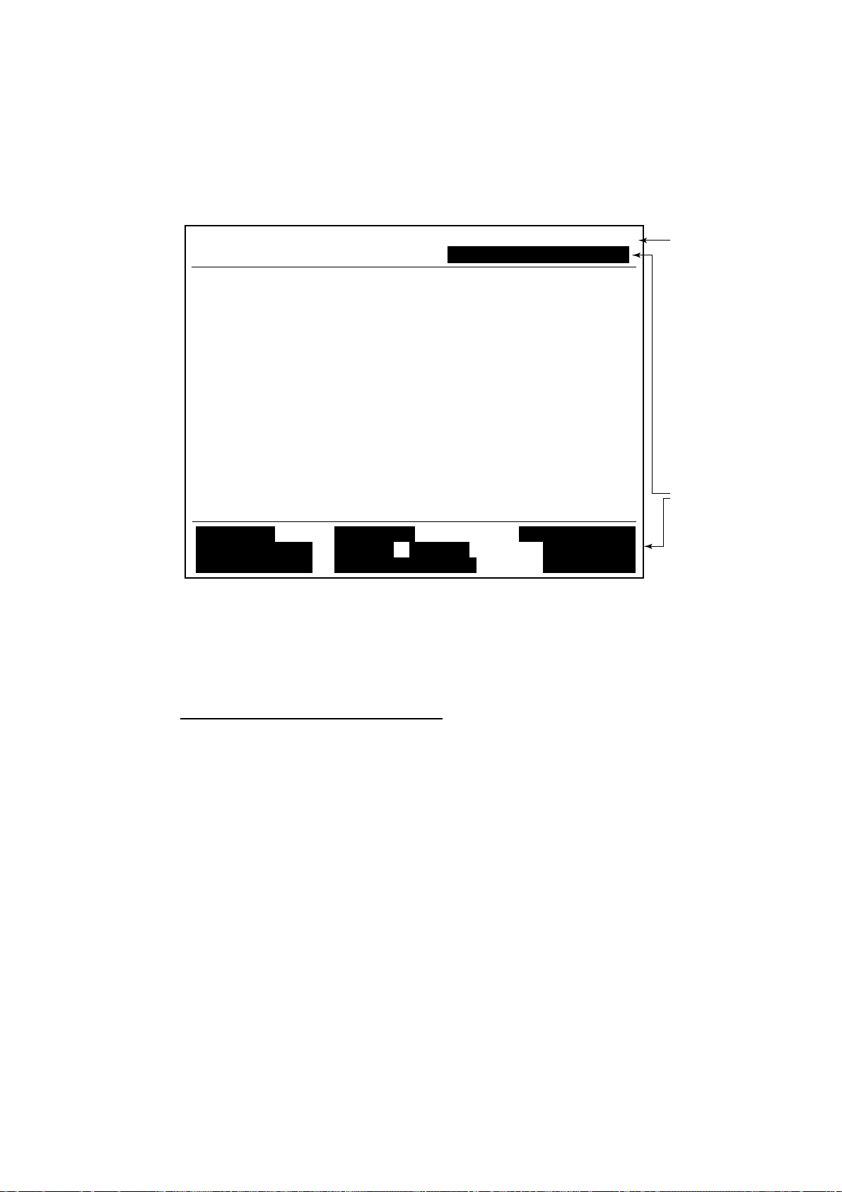
1.3.1 Display indications
The dis play is divided in three sec tions:
1) T he function menu area
2) The working area
3) T he oper ating status area
1. OPERATIONAL OVERVIEW
File Edit Transmit EGC Reports Logs Options Setup Position StopAlarm
(1) (1)
1) Function
Menu
2) WORKING AREA
3) Operating
Status
(2)
(3a)
(3b)
(4)
(5) (6)
(7)
(8)
(9)
(9)
Location of display indications
Below are the indications and m eanings of the items in parentheses in the
illust ration above.
(1) Communication network mode
No display Normal oper ation
Restorati on Mode Problem at NCS
(Flashing)
Restorati on Mode Previously designated LES is transmitting the
(Reverse video) NCS common channel signal.
1-7
Page 28

1. OPERATIONAL OVERVIEW
(2) Communication unit status
IDLE Idle (aw aiting receiving, awaiting transmitting)
IDLE (PE NDING) Awaiting reply from LES
SENDING Sending
RECEIVING Receiving
LOGI N Logged in w ith NCS
LOGOUT Logging out with NCS
Data Repor t Sending data report
TESTING PV (Perform ance Verification) testing
TEST S ETUP Requesting PV testing
SCANNING NCS scanning
EGC RECEIVER EGC-only recei ver ope r ation
(Reverse video)
Delivery Status Req. Transmitting delivery status request
Forced Clearing Stoppi ng r eceiving, transmitting, or scanning
(3a) Communication statu s
CALLING Now calling
WAITING FOR ACKNOWLEDGEM E NT Waiting for acknowledgement fr om
LES.
RECEIVING EGC MESSAGE Now receiving EGC message
WAITING FOR BACKOFF Waiting to transmit data report
Successful Login. Login was successful
Login failed. Login failed
Successful Logout. Logout was successful
Logout failed. Logout failed
Successful Forced Clearing. Forced clearing successful
Forced Clearing Failed. Forced clearing unsuccessful
SENDING MESSAGE PA CKETS Sending TX message packets
WAITING FOR ACKNOWLEDGEM E NT Waiting for acknowledgem ent from LES
Successful s ending to LES. Message successfull y sent to LES
Sending message failed. Message could not be sent to LES
Call rejected. LES reject ed your message
Call pendi ng. LES temporarily suspending
communications
Received Call. Call received from LES
Received Call(ITA2). Call(ITA2) received from LES
RECEIVING MESSAGE PACKETS Receiving message packets
CLEARING Clearing TX sequence
Successful receiving. You successfully received message
Receiving failed. You could not receive message
Successful Data Report. Data report s uc cessfully s ent.
Data Repor t failure. Data report c ould not be sent.
PV TEST CALL is rejected. PV test call rejected by NCS
PV TEST CALL is pending. PV test pendi ng by LES
TEST-RECEIVING MESSAGE Receiving test message from LES
TEST-SENDING MESSAGE Sending test message to LES
1-8
Page 29

1. OPERATIONAL OVERVIEW
TEST-DISTRESS ALERT Sending test distress alert to LES
WAITING FOR ACTIVATION Waiting start of PV test
WAITING FOR TEST RESULT Waiting for results of PV test
CLEARING Clearing PV test
PV TEST is Completed. PV test is completed.
PV TEST Fail ure. PV test failed.
(3b) RF CON board program version number
DCE F16 Ver . XX (XX = Version Number)
(4) Frame synchronization
Blank Changing channel, or during trans m ission
SYNC (NCS) Synchronizing with NCS
SYNC (LES) Sync hr onizing with LES
MES Sig. Ch Trans f er r ing to MES signaling c hannel
MES Msg. Ch T r ans ferring to MES message channel
UNSYNC Out of synchronization
Retuning Synchronizing with NCS or LES
(5) Ocean regi on receiving
No display Out of synch with satellite
AOR-W Atlantic Ocean Region-West
AOR-E Atlantic Ocean Region-East
IOR Indian Ocean Region
POR Pacific Ocean Region
(6) Logging status
LOGOUT Logged out with ocean region
LOGI N Logged in with ocean region
LOGI N (Flashing) Logging i n with ocean region
1-9
Page 30

1. OPERATIONAL OVERVIEW
(7) Other information
No display No receive message in memory, or printer is
REC. MESSAGE EXISTS Display ed when a routine message has
(Reverse video) not been printed, or a confidenti al message is
Data Repor t When data reporting is act ivated.
(Reverse video)
Message Report Message report setting is activated.
(Reverse video)
(8) Date and time
Date and time, received from the GP S navigator, are displayed. Manually input
date and time are also displayed.
(9) Ship’ s positio n
operating.
received.
Ships pos ition, received fr om the GPS navigator, is displayed in l atitude and
longitude and updated every 30 sec onds, or manually input position is displayed.
1-10
Page 31

1.4 Menu Overview
Operation of the FELCOM 16 i s c arr ied out through a menu system which you
access wi th the function keys at the top of the screen. The example below
shows how to choose menu options f rom the Editor Set up m enu.
1. Press the [F8] key to display the Setup menu.
File Edit Transmit EGC Reports Logs Options Setup Position StopAlarm
Setup
1. System Setup
2. Editor Setup
3. Terminal Setup
4. EGC Setup
5. Auto Mode Setup
6. E-Mail Setup
7. Directories
8. Configuration
1. OPERATIONAL OVERVIEW
Setup menu
2. Choos e des ired menu by pressing appropriat e numeric key. For example,
press the [2] k ey to show the Editor S etup menu.
Note: You may also choose a menu by pressing the [↑] or [↓] key to choose it
and then pressing the [Enter] key.
File Edit Transmit EGC Reports Logs Options Setup Position StopAlarm
Setup
Editor Setup
Text Mode
2. System Setup
Edit Mode
3. Editor Setup
Word Wrap
4. Terminal Setup
Line No.
5. EGC Setup
Tab Width
6. Auto Mode Setup
Column Width
7. E-Mail Setup
Cursor Type
8. Directories
Scroll
9. Configuration
Ascii
Insert
ON
ON
4 Char
69
Block
Full Screen
Editor setup menu
3. Choos e des ired menu item by pressing the [↑] or [↓] keys followed by the
[Enter] k ey. A window displaying the options for the item selected or a
alphanumeric data entry window appears depending on your selec tion. For
example, choose Wo rd Wr ap.
ON
OFF
Word wrap options window
1-1 1
Page 32

1. OPERATIONAL OVERVIEW
3. Press the [↑] or [↓] key to choose option desired and press the [Enter] key.
4. Press the [Esc] key.
Note 1: On some menus t he update window appears after you press the [Esc]
key. This is done to ask you to confirm settings . Yes is selected i n the
Update window; press the [E nter] key to register settings, or press [→]
to choose No and press the [Enter] k ey to escape.
Update
Yes No
Note 2: The following functions are not av ailable:
Keying Sequence
Item
F3-1 Selection of Priority on Transmit Message
F8-1 NAV PORT, MESSAGE OUTPUT PORT, ACTIVE
PORT, EGC OUTPUT PORT, NETWORK SETUP
on System S etup menu
F8-4 Wayp oint on EGC Setup
1.5 Error Messages and Alerts
The term inal unit display s er r or m ess ages and alert s to call your attention t o
misoperation, failed operat ion and system error. A list of error messages appears
in Chapter 7 an d alerts in the Appendix.
To erase an error message or alert, press the [Esc] key.
File Edit Transmit EGC Reports Logs Options Setup Position StopAlarm
Log
1. Send Message Log
2. Receive Message Log
Send Message Log
No. Message File Station LES Priority Send Status Delivery
CAUTION
No Message.
<Press ESC key to continue>
Location of er r or messages and alerts
1-12
Page 33

1.6 Choosing a Printer
Choose the printer to use as follows:
1. Press the [F1] key to dis play the File menu.
File Edit Transmit EGC Reports Logs Options Setup Position StopAlarm
File
1. New
2. Open
3. Close
4. Save
ALT-N
ALT-O
ALT-Q
ALT-S
1. OPERATIONAL OVERVIEW
5. Delete
6. Rename
7. Print
8. Print Setting
9. MIME (Decode)
ALT-D
ALT-P
File m enu
2. Press the [8] key to choose 8. Print Set ting.
Print Setting
Please select Printer
and press Enter key.
No Printer
Windows Printer
PP-510
3. Press the [↑] or [↓] key to choose appro pr iate printer.
No Printer: Choose this i tem if no printer is connec ted.
Windows P r inter: Choose if a PC- us e pr inter is connected.
PP-510: Choos e if PP-510 is connected.
4. Press the [Esc] key to finish.
1-13
Page 34

1. OPERATIONAL OVERVIEW
(This page intentionally left blank.)
1-14
Page 35

2. SYSTEM INITIALIZATION
This chapt er pr ovides the informat ion necessary f or initializing the F E LCOM 16.
Once the equipment is initialized, you need do no more than press a few k ey s t o
transmit and r ec eive.
Inmarsat assigns an MES an I nm ars at Mobile Number (IMN) when it appl ies for
Inmarsat registration and it is entered during the installation of the MES. T he
IMN is necessary to communicate in the Inmarsat system.
2.1 System Settings
The System Setup menu provides for input of date, t ime, operating mode, and
port function.
1. Press the [F8] key to choose the S etup menu.
File Edit Transmit EGC Reports Logs Options Setup Position StopAlarm
Setup
1. System Setup
2. Editor Setup
3. Terminal Setup
4. EGC Setup
5. Auto Mode Setup
6. E-Mail Setup
7. Directories
8. Configuration
Setup menu
2. Press the [1] key to display the System Setup menu.
Setup
System Setup
Entered at installation
(Cannot be changed.)
Not used.
System Date & Time
IMN
MES Operation Mode
Nav Port
Active Port
Message Output Port
EGC Output Port
9. Configuration
Network Setup
Command Window
01:53 02-02-25 (YY-MM-DD)
INMARSAT-C
INT
INT
INT
INT
System s et up menu
Note: The IMN number is enter ed during the installation. The number cannot
be changed.
2-1
Page 36

2. SYSTEM INITIALIZATION
3. Press the [↓] key twice t o choos e MES Operation M ode.
4. Press the [Enter] key to open the MES operati on m ode options window.
System s et up menu, MES operati on mode options wi ndow
5. Press the [↓] or [↑] key to choose operating mode, INMARSAT- C or E GC.
The INMA RS AT - C s et ting provides telex communications and operates as an
EGC receive r when the equipment is not transmitting or receiving. The EGC
setting enables EGC-only oper ation. In this c ase, “Cur r ent State: EGC
RECEIVE R” ( in reverse video) at t he bot tom of the screen.
6. Press the [Enter] key to close the window.
7. Press the [Esc] key to open the update window.
Setup
System Date & Time
IMN
MES Operation Mode
Nav Port
Active Port
Message Output Port
EGC Output Port
9. Configuration
Network Setup
Command Window
System Setup
01:53 02-02-25 (YY-MM-DD)
IOR
INMARSAT-C
INMARSAT-C
EGC
OFF
INT
EXT
EXT
Setup
System Setup
For technicians
System Date & Time
IMN
MES Operation Mode
Nav Port
Active Port
Message Output Port
EGC Output Port
9. Configuration
Network Setup
Command Window
01:53 02-02-25 (YY-MM-DD)
INMARSAT-C
INT
INT
INT
INT
Update
Yes No
8. Yes is selected; pr es s the [Enter] key to update system set tings.
9. Press the [Esc] key to retur n to the standby display.
Note: I f t he internal GPS malf unc t ions, enter data m anually as below.
1. Choos e S ystem Date & Time from the System Setup menu and then
press the [Ent er ] key.
Setup
System Setup
02-02-25
System Date & Time
IMN
MES Operation Mode
Nav Port
Active Port
Message Output Port
EGC Output Port
9. Configuration
Network Setup
Command Window
01:53 97-08 (YY-MM-DD)
INMARSAT-C
INT
INT
INT
INT
2-2
Date and time entry window
2. Enter date with the numeric keys.
3. Press the [Enter] key to close the window.
Page 37

2.2 PC Window Setup
The Terminal Setup menu pro vides for set up of the PC window. Set up includes
selection of date display f orm at, currency unit and window colors.
1. Press the [F8] key to choose the S etup menu.
2. Press the [3] key to display the Terminal Setup screen.
Date Disp. Form
Currency Unit
Screen Saver
Window Color
Terminal S et up menu
3. Date Disp. Form is selected; press the [Enter] key to open its options window.
Terminal Setup
YY-MM-DD
US$
ON
YY-MM-DD
MMM-DD-YY
DD-MMM-YY
2. SYSTEM INITIALIZATION
Date options
4. Press the [↓] or [↑] key to choose date display format desired and then press
the [Enter] key to close the window.
5. Press the [↓] key to choose Curr enc y Unit.
6. Press the [Enter] key to open the currency unit options window.
SDR
US$
EUR
YEN
OTHER
Currency unit options
7. Press the [↓] or [↑] key to choose the currency unit to use to calculate toll
charges. S DR m eans Spec ial Drawing Ri ght and it is the common unit
charge used by all LES to assess toll charges. For OTHER, enter currency
unit name (4 characters max.). Your selection appea r s nex t to Currency Uni t
in the Terminal Setup menu.
8. Press the [Enter] key to close the window.
9. Press the [↓] key to choose Window Color and press the [Enter] key.
Window Color
Window Color Setup
Default Color
Window c olor menu
2-3
Page 38

2. SYSTEM INITIALIZATION
10. You may change the background and foregroun d c olors for the various
display screens on the PC wi ndow as follows:
a) Choose Window Color Setup.
b) Window is selected; press the [→] or [←] key to choose the item to adjust.
BASE WINDO W: S t and by display
RCV Message Display: Communications memory display
EGC Message Display: Communications display
EDIT1 – EDIT 2 Editor screens
Function: Menu
Sub Menu1 – Sub Menu4: Sub menus
Message: Status message
Window Color Setup
Window : Base Window
Fore Color : L_WHITE
Back Color : BLUE
To Change: ENTER To Change Value: L<=>R
Window c olor setup menu
MENU
EDIT
File Edit Transmit EGC Reports Logs Options Setup Position StopAlarm
1:
2:
|
|
|
|
|
|
|
< [1] UNTITLED1 >
CAUTION
BASE WINDOW
MESSAGE
Location of items
c) Press the [↓] key to choose Fore Color.
d) Press the [→] or [←] key to choose foreground color desired
e) Press the [↓] key to choose Back Color.
f) Press the [→] or [←] key to choose background color.
g) To change the color of other windows, repeat steps b-f.
h) Finally press the [Enter] key to show the Update window.
i) Yes is selected; press the [Enter] key.
2-4
Note: To restore all default color settings, choose Win dow Color from the
Terminal Setup m enu, choose Default Color and then press the [E nter]
key. Yes is selected; press the [Enter] key.
11. Press the [E s c ] key three times t o return to the standby display.
Page 39

2.3 Login and Logout
Each time the terminal unit is turned on, register your vessel wit h the I nm ar s at C
system to enable communications between your vessel and an LES. This is
called login.
Note that you can transmit or rec eive EGC messages even if you are not logge d
in.
If you will not be using the FELCO M 16 for a prolonged per iod, you should
logout from the Inmarsat C system, before turning off the termi nal unit. The
Inmarsat C system will then register you as inac tive, notifying anyone trying t o
call you that you are currently unavailable. If y ou do not log out before turning off
the power, some LESs may attem pt to send a message to you. They may
charge y our c orr es pondent, even if you don’t receive the message.
2.3.1 Login
2. SYSTEM INITIALIZATION
1. Confirm that “SYNC ( NCS ) ” appears at the bottom of the screen.
2. Press the [F7] key to dis play the Options menu.
File Edit Transmit EGC Reports Logs Options Setup Position StopAlarm
Options
1. Login
2. Logout
3. Abort
4. Select NCS
5. Ocean Region
6. LES Information
7. Test
Options menu
3. Press the [1] key to display the Login screen.
Options
Login
Start
Yes
No
Login scree n
2-5
Page 40

2. SYSTEM INITIALIZATION
Note: The terminal uni t must be “idle” to l ogin. (“Current State: IDLE”
appears at t he bottom of the screen. ) When it is not idle, “Ignored:
MES is not idle.” appears. Press the [Esc] key to return to the standby
display. Wait until the terminal unit bec om es idle.
4. Yes is selected; pr es s the [Enter] key to start login.
5. Login begins and the screen s hould now l ook s omething like the illustration
below, with “LOGIN” flashing.
File Edit Transmit EGC Reports Logs Options Setup Position StopAlarm
Options
Login
Starting Login Process.
Press any key to escape.
Current State: LOGIN
CALLING
DCE F16 Ver. **
LOGIN replaces IDLE.
SYNC ( NCS )
NCS: IOR LOGIN
Flashing during login
02-02-25 02:02 (UTC)
LAT: 34:30.00N
LON: 135:30.00E
Appearanc e of display screen during login
When login is completed, the m ess age “ S uc cessful login.” appears. Then,
the termi nal unit goes into “I dle” status and LOGIN stops blinki ng.
6. Press any key to return to the standby display.
2-6
Page 41

2.3.2 Logout
1. Press the [F7] key to dis play the Options menu.
2. Press the [2] key to display the logout screen.
Note: The terminal uni t must be “idle” to l ogout. When it is not idl e, “Ignored:
MES is not idle.” appears. Press the [Esc] key to return to the standby
display. Wait until the terminal unit bec om es idle.
File Edit Transmit EGC Reports Logs Options Setup Position StopAlarm
2. SYSTEM INITIALIZATION
Options
Logout
Start
Yes No
Current State: IDLE
Successful Login.
DCE F16 Ver.**
SYNC ( NCS )
NCS: IOR LOGIN
02-02-25 02:04 (UTC)
LAT: 34:30.00N
LON: 135:30.00E
Options menu, logout screen
3. Yes is selected; pr es s the [Enter] key to start logout. The screen now looks
something like the illustration below.
File Edit Transmit EGC Reports Logs Options Setup Position StopAlarm
Options
Logout
Starting Logout Process.
Press any key to escape.
Current State: LOGOUT
CALLING
DCE F16 Ver. **
SYNC ( NCS )
NCS: IOR LOGIN
02-02-25 02:02 (UTC)
LAT: 34:30.00N
LON: 135:30.00E
Appearanc e of display screen during logout
4. When logout is completed, “Successful Log out.” appears. “ Cur r ent State”
then returns to IDLE.
5. Turn off the FELCOM 16.
2-7
Page 42

2. SYSTEM INITIALIZATION
2.4 EGC Settings
2.4.1 What is the EGC (Enhanced Group Call) service?
The EGC s er vi ce enables EGC informat ion providers to s end S afetyNETTM,
TM
FleetNET
and System m ess ages vi a an LES to a specific groups of ships, or
to all s hips within a defined geographical area.
Each type of EGC service is sent as follows:
1) The i nformation provider prepares the message, and then accesses t he
appropriate Country of t he international t elex network to send the message
to an LES.
2) The LES pr oc es ses and forwards it to the NCS for the ocean region
designate d by the provider.
3) Then, the NCS broadcasts the message throughout the ocean region. ( The
operator may choose the EGC messages to receive by pos ition (one
positi on) and geographical position (nine areas). For further details see
paragraph 2.4.2.)
Satellite
Information Provider
* Meteorological body
* Navtex station
* Coast guard
* Rescue center
* Shipping company,
etc.
LES1
LES2
LES3
Ch1
Ch2
Ch3
NCS
NCS common channel
MES
MES
MES
Ch1-Ch3 are dedicated
channels for each LES.
The EGC system
Three EG C s er vic es ar e available:
1) SafetyNET
TM
This provides a m eans for informat ion providers to distribute Marit ime Safety
Inform ation (MSI) from shore-t o- s hip. Authorized inf or mation providers
include:
a) Hydrographic Offices, for navigational warnings
b) National Weather Services, for meteor ological warnings and forecast s
c) Rescue Co-ordination Center, for shore-to-ship distress alerts and other
urgent i nformation
d) International I c e P atrol, for North Atlantic ice haz ar ds
2-8
Page 43

2. SYSTEM INITIALIZATION
2) FleetNETTM
This servic e allows authori z ed information providers such as commercial
subscription services, shipping companies and governments, which have
registered with a LES that suppor ts FleetNET
selected group of MESs. Typical applicat ions of FleetNET
TM
, to broadcast messages to
TM
are
a) Fleet or company br oadc as ts
b) News broadcasts
c) Commercial weather services
d) Market quotations
e) Government broadcasts to all vessel s on a c ountry’s registration
3) Syst em
EGC system-related is sent by Inmarsat to certain ship groups and
geographical areas.
2-9
Page 44

2. SYSTEM INITIALIZATION
2.4.2 EGC setup
The FELCOM 16 receives EGC mess ages directed to i ts present positi on and
Navarea without further programming. The EGC Setup screen lets you choose
additional areas for which to receive messages and also the Navtex station and
type of m es sage for Coastal Warning (NAVTEX Re-broadcast).
1. Press the [F8] key to dis play the Setup menu.
File Edit Transmit EGC Reports Logs Options Setup Position StopAlarm
Setup
1. System Setup
2. Editor Setup
3. Terminal Setup
4. EGC Setup
5. Auto Mode Setup
6. E-Mail Setup
7. Directories
8. Configuration
Setup menu
2. Press the [4] key to display the EGC Setup menu.
Setup
EGC Setup
Receive EGC Area
Notused.
Additional Position
Navarea
Fixed Area
Waypoint (from NAV Equipment)
NAVTEX
Station Code
Type of Message (Can't reject other report)
Ice reports
Meteo. forecasts
Pilot service
DECCA messages
LORAN messages
OFF
OFF
OFF
OFF
OFF
: :
OFF
OMEGA messages
SATNAV messages
Other navaid msg
QRU (no message)
OFF
OFF
OFF
OFF
EGC setup menu
3. The cursor is selecting Addi tional Position, where you can enter the L/L
positi on of an ocean region you want to receive broadcasts about. Press t he
[Enter] k ey to open the additi onal position entry window .
4. Enter pos ition as follows:
a) Enter latitu de (XX ° XX ).
b) Press the [N] or [S] key as appropriate to enter coordinate.
c) Enter longitude (XX X° XX).
d) Press the [E] or [W] key as appropriate enter coordinate.
5. Press the [Enter] key to close the additional position entry window.
6. Press the [↓] key to choose Nav area.
2-10
Page 45

2. SYSTEM INITIALIZATION
7. Press the [Enter] key to open the navarea entry window.
Setup
EGC Setup
Receive EGC Area
Additional Position
Navarea
Fixed Area
Waypoint (from NAV Equipment)
NAVTEX
Station Code
Type of Message (Can't reject other report)
Ice reports
Meteo. forecasts
Pilot service
DECCA messages
LORAN messages
OFF
OFF
OFF
OFF
OFF
: :
OFF
OMEGA messages
SATNAV messages
Other navaid msg
QRU (no message)
OFF
OFF
OFF
OFF
EGC setup menu, Navarea entry w indow
8. Enter additional Navare a( s ) ( I-XVI, up to nine) in two digit s
illust ration below for code numb er.
, referring to the
Navareas
9. Press the [Enter] key to close the navarea entry window.
Note: “Fixed Area” is where you enter fixed areas (ma x . 3) for chart
correction s ervice. However, this service is not yet available; enter no
data.
2-1 1
Page 46

2. SYSTEM INITIALIZATION
10. Press the [↓] key to choose Station Code.
11. Press the [Enter] key to open the station code entry window.
12. Enter the navtex station code (A-Z ) of the navarea, in upper c ase alphabet.
For details about navtex st ations, consult the operator’s manual of the navtex
receiver.
13. Press the [Enter ] key to close the station code entry window.
14. Choose message type to receive:
a) Press the [↓] or [↑] key to choose message type.
b) Press the [Enter] key.
c) P re ss the [↓] or [↑] key to choose ON or OFF as appropriate.
d) Repeat a) thru c) to set other message types.
e) Press the [Enter] key.
Setup
EGC Setup
Receive EGC Area
Additional Position
Fixed Area
Waypoint (from NAV Equipment)
NAVTEX
Station Code
Type of Message (Can't reject other report)
Navarea
Ice reports
Meteo. forecasts
Pilot service
DECCA messages
LORAN messages
OFF
OFF
OFF
OFF
OFF
: :
OFF
OMEGA messages
SATNAV messages
Other navaid msg
QRU (no message)
OFF
OFF
OFF
OFF
EGC setup menu, station c ode entry window
Note: Navtex m es sages “Coastal navigational information”, “ Meteorological
warning” and “Search and rescu e alert” (they do not appear on the
EGC Setup menu) must always be received.
15. Press the [Esc] key to open the update window.
Setup
EGC Setup
Receive EGC Area
Additional Position
Navarea
Fixed Area
Waypoint (from NAV Equipment)
NAVTEX
Station Code
Type of Message (Can't reject other report)
Ice reports
Meteo. forecasts
Pilot service
DECCA messages
LORAN messages
OFF
OFF
OFF
OFF
OFF
: :
OFF
OMEGA messages
SATNAV messages
Other navaid msg
QRU (no message)
OFF
OFF
Update
OFF
OFF
Yes No
EGC setup menu, update window
16. Yes is selected; press the [Enter] key to update EGC settings.
17. Press the [Esc] key to return to the standby display.
2-12
Page 47

2.4.3 Adding EGC channels
The EGC Channel List stores EGC channels. There are currently four EGC
channels, one for each satellite. These four channels are pre-pro gram med into
the unit and marke d in the EGC Channel List with asterisks. When more EGC
channels bec ome available you can add them to the list as below.
1. Press the [F8] key to dis play the Setup menu.
2. Press the [8] key to display the Configurati on m enu.
3. Press the [3] key to display the EGC Channel List.
File Edit Transmit EGC Reports Logs Options Setup Position StopAlarm
Setup
Configuration
EGC Channel List
ENTER: Set ESC: Quit
2. SYSTEM INITIALIZATION
11080*
12580* 10840* 11088*
EGC channel list
4. Usi ng the arrow keys, place the cursor where t her e is no data entered.
Current EGC channels are marked with an asterisk. These channel s c annot
be changed.
2-13
Page 48

2. SYSTEM INITIALIZATION
5. Press the [Enter] key to open the EGC channel list entry screen.
Setup
Configuration
EGC Channel List
ENTER: Set ESC: Quit
11080* 10840* 11088*
12580*11080*
EGC channel list entry screen
6. Enter E GC channel frequenc y code. The EG C channel frequency c ode r ange
is 6000-14000.
7. Press the [Enter] key to close the text window.
8. Press the [Esc] key to open the update window.
Setup
Configuration
EGC Channel List
ENTER: set ESC: quit
11080* 12580* 10840* 11088*
Update
Yes No
EGC channel list, update w indow
9. Yes is selected; pr es s the [Enter] key to register input.
Note: If the EGC channel f r equency code entered is invalid, the message "Input
Error: Chan nel No." appears. Cl ear the error message by pressing the
[Esc] key. Place the cursor at the invalid frequenc y, press the [Ent er ] key
and enter corr ect frequency.
10. Press the [Esc] key twice to return to the standby display.
2-14
Page 49

2. SYSTEM INITIALIZATION
2.4 .4 Saving, printing EGC messages automatically
You may choose the EGC messages to save and pr int as follows :
Automat i cally saving EGC messages
1. Press the [F8] key to display the Setup menu.
2. Press the [5] key t o dis play the A uto Mode Setup menu.
Auto Mode Setup
Auto Log Print OFF
Receive Alarm OFF
Auto Receive Message Save OFF
Auto Receive Message Print OFF
Data Report & Polling Print OFF
Auto EGC Message Save
Auto EGC Message Print
Auto EGC message save menu
3. Press the [↓] or [↑] key to choose Auto EGC Message Save and then press
the [Enter] key .
Auto Mode Setup
Auto EGC Message Save
System OFF
FleetNET OFF
SafetyNET (Routine) OFF
SafetyNET (Safety) OFF
SafetyNET (Urgent & Distress) ON
Auto EGC message print menu
4. Press the [↓] or [↑] key to choose message t ype and then press the [Enter]
key.
5. Choose ON or OFF as appropriate and press th e [Enter] key to cl os e the
window.
6. Press the [Esc] key three times to return t o the standby di s play.
2-15
Page 50

2. SYSTEM INITIALIZATION
Automat ically printing E GC messages
1. Press the [F8] key to display the Setup menu.
2. Press the [5] key t o dis play the A uto mode setup menu.
3. Press the [↓] key to choose Auto EGC Message P r int and then press the
[Enter] k ey.
4. Press the [↓] or [↑] key to choose message t ype and then press the [Enter]
key.
5. Choose ON or OFF as appropriate and press th e [Enter] key to cl os e the
window.
6. Press the [Esc] key three times to return t o the standby di s play.
Auto Mode Setup
Auto EGC Message Print
System OFF
FleetNET OFF
SafetyNET (Routine) OFF
SafetyNET (Safety) OFF
SafetyNET (Urgent & Distress) OFF
Auto EGC message print menu
2-16
Page 51

2.5 Adding NCS Channels
This sect ion shows you how to add NCS c hannels to the NCS Channel List. 19
channels c an be listed per each ocean region. Current ly, there are four N CS
channels, and t hey are marked with asterisks in the list. Add NCS channels to
the lis t as below when they become operational.
1. Press the [F8] key to dis play the Setup menu.
2. Press the [8] key to display the Configurati on m enu.
3. Press the [4] key to display the NCS Channel Lis t.
Setup
Configuration
NCS Channel List
2. SYSTEM INITIALIZATION
ENTER: Set ESC: Quit
No
2
3
4
5
6
7
8
AOR (WEST)
FREQ
ID
11080*1
044
0
0
0
0
0
0
0
AOR (EAST)
FREQ
ID
12580*
144
1
1
1
1
1
1
1
ID
244
2
2
2
2
2
2
2
POR
FREQ
12580*
ID
344
3
3
3
3
3
3
3
IOR
FREQ
10840*
NCS channel list
4. Use the ar r ow keys to place the cursor in a blank ID column.
5. Press the [Enter] key to open the data entry window.
6. Enter NCS c hannel ID number, in two digits. (Entry of leading zero is not
necessary.) The ID number range is 45-63.
7. Press the [Enter] key to close the window.
8. With the [→] key, choose the frequency column.
9. Press the [Enter] key to open the frequency entry window.
10. Enter NCS chann el frequency code. The frequency code range is
6000-14000.
11. Press the [Enter] key to close the window.
12. Press the [Esc] key to open the update window.
Setup
Configuration
NCS Channel List
ENTER: Set ESC: Quit
No
1
2
3
4
5
6
7
8
AOR (WEST)
FREQ
ID
11080*
044
0
0
0
0
0
0
0
AOR (EAST)
FREQ
ID
12580*
144
1
1
1
1
1
1
1
ID
244
2
2
2
2
2
2
2
POR
12580*
FREQ
IOR
FREQ
ID
10840*
344
3
3
3
Update
3
3
Yes No
3
Yes
3
NCS channel list, update window
2-17
Page 52

2. SYSTEM INITIALIZATION
13. Yes is selected; press the [Enter] key to regi s ter input.
Note: If the ID or frequency entered is invalid the message "Input E r r or: NCS
ID" (for i nval id ID) or "Input Error : Channel No." (for invalid frequency)
appears. Clear the error message by pressing the [ E s c] key. Place the
cursor at the invalid ID or frequenc y code. T hen, press the [Enter] key
and enter corr ect ID or frequency.
14. Press the [Esc] key twice to return to the standby display.
2-18
Page 53

2.6 LES List
The LES List provides for storage of 44 LES names per ocean region. By
entering approximate toll charges in the L ES list, you can see that informat ion on
the Transmit message menu.
2.6.1 Setting toll charges
Main LES (LES name and ID) are already registered in the FELCOM 16; but, t oll
charges are not set. To set communication toll charges do the following:
1. Press the [F8] key to display the Setup menu
File Edit Transmit EGC Reports Logs Options Setup Position StopAlarm
Setup
1. System Setup
2. Editor Setup
3. Terminal Setup
4. EGC Setup
5. Auto Mode Setup
6. E-Mail Setup
7. Directories
8. Configuration
2. SYSTEM INITIALIZATION
Setup menu
2. Press the [8] key to display the Configuration menu.
Setup
Configuration
1. Station List
2. LES List
3. EGC Channel List
4. NCS Channel List
5. E-Mail/SMS Service List
6. Save/Load
8. Directories
9. Configuration
Configuration menu
2-19
Page 54

2. SYSTEM INITIALIZATION
3. Press the [2] key to display the LES List.
LES List
Ctrl+P: Print ENTER: List Entry ESC: Quit
No
Telenor S.S.Inc
01
Stratos M.N.
02
KDDI
03
Telenor S.S.AS
04
05
06
07
08
AOR (WEST)
Name
AOR (EAST)
Name
Telenor S.S.Inc
Stratos M.N.
KDDI
Telenor S.S.AS
Telecom Italia
POR
Name
Telenor S.S.Inc
Stratos M.N.
KDDI
Telenor S.S.AS
Korea Telecom
IOR
Name
Stratos M.N.
KDDI
Telenor S.S.AS
OTE
VSNL
Korea Telecom
LES list
4. Using the arrow keys, choose the LES for which you want to enter toll
charges. For example, choose KDDI (Japan).
5. Press the [Enter] key.
Setup
Configuration
LES List
Ctrl+P: Print ENTER: List Entry ESC: Quit
No
01
02
03
04
05
06
07
08
AOR (WEST)
Name
Telenor S.S.Inc
Stratos M.N.
KDDI
Telenor S.S.AS
AOR (EAST)
Name
Telenor S.S.Inc
Name
GOONHILLY
ID
BURUM/YAMAGUCHI
Remarks
EIK/TELENOR
Charge (US$/256bit)
FUCINO
TELEX *****.**
FAX *****.**
E-Mail *****.**
SMS *****.**
PSDN *****.**
X400 *****.**
DNID *****.**
SPEC *****.**
Erase the Name to delete this LES.
:
: 005
:
POR
Name
Telenor S.S.Inc
NETELY/BT/TELEN
YAMAGUCHI
KUMSAN
IOR
Name
Stratos M.N.
KDDI
Telenor S.S.NS
OTE
VSNL
Korea Telecom
2-20
LES list, LES data entry window
6. Press the [↓] key to choose TELEX and press the [Enter] key to open the text
entry window.
7. Enter telex charges (per 256 bit) and press the [Enter] key.
For toll charges, contact appropriate LES.
8. Enter toll charges for other items similarly.
9. Press the [Esc] key to return to the LES list.
10. Press the [Esc] key three times to return to the standby display.
Page 55

2.6.2 Registering LES to LES list
Follow the procedure below to register newly constructed LESs.
1. Press the [F8], [8] and [2] keys to show the LES list.
2. Use the arrow keys to place the cursor where desired. For example, choose
005 in the AOR(WEST) column.
Setup
Configuration
2. SYSTEM INITIALIZATION
LES List
Ctrl+P: Print ENTER: List Entry ESC: Quit
Telenor S.S.Inc
01
Stratos M.N.
02
KDDI
03
Telenor S.S.AS
04
05
06
07
08
AOR (WEST)
Name
No
Place cursor here.
LES ID: XXX
3. Press the [Enter] key.
Setup
Configuration
AOR (EAST)
Name
Telenor S.S.Inc
Stratos M.N.
KDDI
Telenor S.S.AS
Telecom Italia
No. (00-43)
0: AOR(WEST)
1: AOR(EAST)
2: POR
3: IOR
Configuration menu
LES List
POR
Name
Telenor S.S.Inc
Stratos M.N.
KDDI
Telenor S.S.AS
Telenor S.S.AS
Korea Telecom
Ctrl+P: Print ENTER: List Entry ESC: Quit
IOR
Name
Stratos M.N.
KDDI
Telenor S.S.AS
OTE
VSNL
Korea Telecom
No
01
02
03
04
05
06
07
08
AOR (WEST)
Name
Telenor S.S.Inc
Stratos M.N.
KDDI
Telenor S.S.AS
AOR (EAST)
Name
Telenor S.S.Inc
Name
GOONHILLY
ID
BURUM/YAMAGUCHI
Remarks
EIK/TELENOR
Charge (US$/256bit)
FUCINO
TELEX *****.**
FAX *****.**
E-Mail *****.**
SMS *****.**
PSDN *****.**
X400 *****.**
DNID *****.**
SPEC *****.**
Erase the Name to delete this LES.
:
: 005
:
POR
Name
Telenor S.S.Inc
NETELY/BT/TELEN
YAMAGUCHI
KUMSAN
IOR
Name
Stratos M.N.
KDDI
Telenor S.S.NS
OTE
VSNL
Korea Telecom
LES list options
4. Name is selected; press the [Enter] key to open the text entry window.
2-21
Page 56

2. SYSTEM INITIALIZATION
5. Enter LES name (maximum 15 characters).
6. Press the [Enter] key.
7. Press the [↓] key twice to choose Remarks.
8. Press the [Enter] key.
9. Enter remarks (up to 20 characters).
10. Press the [Enter] key.
11. Press the [↓] key to choose TELEX and press the [Enter] key.
12. Enter TELEX toll charges (per 256 bit) and press t he [Enter] key.
13. Enter toll charges f or other items similarly.
14. Press the [Esc] key to return to the LES list.
15. Repeat steps 2-14 to enter another LES.
16.Press the [Esc] key three times to return to the standby display.
2.6.3 Editing the LES list
Name :
ID :
Remarks :
Charge (US$/256bit)
TELEX *****.**
FAX *****.**
E-Mail *****.**
SMS *****.**
PSDN *****.**
X400 *****.**
DNID *****.**
SPEC *****.**
Erase the Name to delete this LES.
LES list, text entry window
1. Press the [F8], [8] and [2] keys to shown the LES list.
2. Use the arrow keys to choose the LES you want to edit.
3. Press the [Enter] key.
4. Do the following:
Change station name: Press the [↓] or [↑] key to choose Name and then
press the [Enter] key. Press the [Backspace] key to erase name and then
enter new name. Press the [Enter] key.
Delete station: Press the [↓] or [↑] key to choose Name and then press the
[Enter] key. Press the [Backspace] key to erase name and then press the
[Enter] key.
5. Press the [Esc] key to quit.
6. Press the [Esc] key three times to return to the standby display.
2-22
Page 57

2.6.4 Printing the LES list
1. Press [F8], [8] and [2] to display the LES lis t.
2. To print the LES list, pres s the [P] key while pressing the [Ctrl] k ey.
LES List ( Printed at 02-02-25 02:33 )
+++++ AOR (WEST) ++++
Name
No.
Telenor S.S.Inc
01
Stratos M.N.
02
KDDI
03
Telenor S.S.AS
04
Xantic (NED)
12
France Telecom
21
Xantic (AUS)
22
+++++ AOR (EAST) +++++
Name
No.
Telenor S.S.Inc
01
LES ID
001
002
003
004
012
021
022
LES ID
101
2. SYSTEM INITIALIZATION
Remarks
USA
CANADA
JAPAN
NORWAY
NETHERLANDS
FRANCE
AUSTRALIA
Remarks
USA
Sample LES list printout
3. To return to the standby display, press the [Es c ] key three times.
2-23
Page 58

2. SYSTEM INITIALIZATION
2.7 Station List
2.7.1 Adding stations to the station list
The FELCOM 16 provides an “address book” for storing 64 station IDs. Enter
station IDs as below.
1. Press the [F8] key to display the Setup menu.
2. Press the [8] key to display the Configuration menu.
3. Press the [1] key to display the Station List.
File Edit Transmit EGC Reports Logs Options Setup Position StopAlarm
Setup
Configuration
Station List
Group Station Name Type Code ID / Address
abc
01
xyz
02
Seagull
03
04
05
06
07
08
Sort (Ctrl+G: Group, Ctrl+N: Station Name, Ctrl+T: Type)
E-Mail
E-Mail
TELEX
abc@ furuno.co.jp
xyz@ furuno.co.jp
584 463609999
Ctrl+P: PrintPage Up, Page Down: Move
Sample station list
4. Operate the [↓] key to place the cursor on a blank line.
5. Press the [Enter] key.
Station Group
Station Name
Destination Type TELEX
Prefix Code
Country Code
Station ID
Modem Type
Address
Remarks
Erase the Name to delete this station.
Station list items
6. Press the [Enter] key to open the station group entry window.
7. Enter station group name, using up to five characters.
8. Press the [Enter] key to close the window.
9. Press the [↓] key to choose Station Name.
10. Press the [Enter] key to open the station name entry window.
11. Enter station name, using up to 15 characters.
12. Press the [Enter] key to close the window.
13. Press the [↓] key to choose Destination Type.
14. Press the [Enter] key to open the destination type window.
2-24
Page 59

2. SYSTEM INITIALIZATION
TELEX
FAX
E-Mail
SMS
PSDN
X400
DNID
SPEC
TELEX (Prefixed)
FAX (Prefixed)
PSDN (Prefixed)
X400 (Prefixed)
DNID (Prefixed)
SPEC (Prefixed)
Destination (communication) type opt ions
TELEX: Telex communication
FAX: Facsimile service
E-Mail: E-mail (electronic mail) Service
SMS: Short Message Service
PSDN: Packet Switched Data Network
- to an office computer via a data network using X.25 standard.
X400: For future use
DNID: Data Network ID. See page 5-12.
SPEC: Ship-to shore requests for safety service, accessed by using special
code numbers
15. Press the [↓] or [↑] key to choose destination type desired.
16. Press the [Enter] key to close the window. Follow appropriate procedure on
the next several pages.
Procedure for Telex
1. Press the [↓] key to choose Country Code.
2. Press the [Enter] key.
3. For ship-to-shore telex, enter international telex country code; ship-to-sh ip
telex, enter ocean region. A list of in ternational telex country codes appears
in the Appendix.
Ocean Region
AOR-East: 581 POR: 582
IOR: 583 AOR-West: 584
4. Press the [Enter] key.
5. Press the [↓] key to choose Station ID.
6. Press the [Enter] key to open the station ID entry window.
7. Enter telex subscriber number (for ship-to-shore) or MES Inmarsat Mobile
Number (for ship-to-ship). Up to 15 characters, including space, can be
entered.
8. Press the [Enter] key to close the window.
9. Press the [↓] key to choose Remarks.
10. Press [Enter] to open the remarks entry window.
11. Enter remarks, using up to 20 characters.
2-25
Page 60

2. SYSTEM INITIALIZATION
12. Press the [Enter ] key to close the wi ndow.
13. Press the [Esc] key to return to the station list.
14. To enter another “Telex” station repeat the procedure fr om s tep 4 on page
2-24.
15. Press the [Esc] key three times to return to the standby display.
Procedure for FAX
1. Press the [↓] key to choose Country Code.
2. Press the [Enter] key to open the country c ode entry window.
3. Enter international telephone code of subscriber. See the Appendix for list of
telephone c odes .
4. Press the [Enter] key to close the window.
5. Press the [↓] key to Station ID.
6. Press the [Enter] key to open the station ID entry window.
7. Enter fax number.
8. Press the [Enter] key to close the window.
9. Press the [↓] key to choose Modem Type.
10. Press the [Enter] key to open the modem ty pe options window.
Modem Type
T30
V21
V22
V22B
V23
V26B
V26T
V27T
V32
Other
FAX
V.21
V.22
V.22bis
V.23
V.26bis
V.26ter
V.27ter
V.32
300bps Duplex
1200bps Duplex
2400bps Duplex
600/1200bps
2400/1200bps
2400bps Duplex
4800/2400bps
9600bps Duplex
Modem type options window
11. Press the [↓] or [↑] key to choose mode t ype of subscriber. For a landline f ax
or a fax-equipped Inmarsat B MES, choose “T30 FAX.”
12. Press the [Enter] key to close the window.
13. Press the [↓] to choose Remarks.
14. Press the [Enter] key.
15. Enter remarks, using up to 20 characters.
16. Press the [Enter] key to close the window.
17. Press the [Esc] key to return to the station list.
18. To enter another “F ax” s tation repeat the procedure from st ep 4 on page
2-24.
19. Press the [Esc] key three times to retur n to the standby display.
2-26
Page 61

2. SYSTEM INITIALIZATION
Procedure for E-mail
1. Press the [↓] key to choose Address.
2. Press the [Enter] key to open the e-mail address entry window.
3. Enter recipient’s e-mail address.
4. Press the [Enter] key to close the window.
5. Press the [↓] to choose Remarks.
6. Press the [Enter] key.
7. Enter remarks, using up to 20 characters.
8. Press the [Enter] key to close the window.
9. Press the [Esc] key to return to the station list.
10. To enter another “E-mail” station repeat the procedure from step 4 on page
2-24.
11. Press the [Esc] key three times to return to the standby display.
2-27
Page 62

2. SYSTEM INITIALIZATION
2.7 .2 Editing the station list
1. Press [F8], [8] and [1] to display the Station List.
File Edit Transmit EGC Reports Logs Options Setup Position StopAlarm
Setup
Configuration
Group Station Name Type Code ID / Address
Station List
abc
01
xyz
02
Seagull
03
04
05
06
07
08
Sort (Ctrl+G: Group, Ctrl+N: Station Name, Ctrl+T: Type)
E-Mail
E-Mail
TELEX
abc@ furuno.co.jp
xyz@ furuno.co.jp
584 463609999
Ctrl+P: PrintPage Up, Page Down: Move
Station list
Note: You may sort the list by group name, station nam e or c om m unication
type as f ollows:
Group name: Each press of [Ctrl] + [G] sort s the list by group name,
ascending or des cending order.
Station name: Each press of [Ctrl] + [N] s orts the list by st ation name,
in ascending or descending order.
Comm. type: Each press of [Ctrl] + [T] sorts the list by communication
type, in as cending or descendi ng or der.
2. Press the [↓] or [↑] key to choose a stat ion and then press the [E nter] key.
3. Do one of the following:
Change station name: Press the [↓] or [↑] key to choose Station Name and
then press the [Enter] key. Press the [Backspace] key to erase station name
and then enter new data. Pres s the [Enter] key.
Delete station: Press the [↓] or [↑] key to choose S tation Name and then
press the [Enter] key. Press the [Backspace] key to erase station name and
then press the [E nter] key.
4. Press the [Esc] key to save changes.
5. Press the [Esc] key three times to return to the s tandby display.
2-28
Page 63

2.7.3 Printing the station list
1. Press [F8], [8] and [1] to display the Station List.
2. press the [P] key while pr es sing the [Ctrl] k ey.
Station List ( Printed at 02-02-25 02:38 )
No.
Group Name
01
x1 abc
02
x2 xyz
03
x3 Seagull
Type
E-Mail
E-Mail
TELEX
Dest, ID, Modem / Address
abc@ furuno.co.jp
xyz@ furuno.co.jp
584 463609999
2. SYSTEM INITIALIZATION
Remarks
Station Name
Group Name
Country Code
Subscriber's Number
Sample station list printout
3. Press the [Esc] key three times to return to the s tandby display.
2-29
Page 64

2. SYSTEM INITIALIZATION
2.8 Entering Own Ship’s Position
When the int er nal GPS navigator is abnormal, manually enter position as below.
1. Press the [F9] key to dis play the Position menu.
File Edit Transmit EGC Reports Logs Options Setup Position StopAlarm
Ship Position
LAT
LON
2. Press the [Enter] key to open the latitude entry window.
34:30.00N
135:30.00E
Ship position window
Ship Position
LAT
LON
00:00.00N
34:30.00N
000:00.00E
Latitude ent r y window
3. Enter latitude (XX° XX) and then press the [N] or [S] key as appropriate to
enter coordinate.
4. Press the [Enter] key to close the window.
5. Press the [↓] key to choose LON.
6. Press the [Enter] key to open the longitude entry window.
Ship Position
LAT
LON
00:00.00N
135:30.00E
000:00.00E
Longitude entry window
7. Enter longitude (XXX° XX) and then press the [E] or [W] key as appropriate
to enter coordi nate.
8. Press the [Enter] key to close the window.
9. Press the [Esc] key to open the update window.
File Edit Transmit EGC Reports Logs Options Setup Position StopAlarm
Ship Position
Update
34:50.00N
000:00.00E
LAT
LON
2-30
No
Yes
Ship position, update
10. Yes is selected; press the [Enter] key to update position and close the S hip
Position menu. The posit ion entered appears at the bottom right corner of the
system status monitor screen.
Page 65

2. SYSTEM INITIALIZATION
2.9 Creating A Directory
Incoming and outgoing messages may be saved to the hard disk. If no directory
is specified, all messages are saved to the My Documents folder (in Windows
Vista, messages are saved to the Felcom16 folder in Documents).
2.9.1 Creating a directory where to store messages
The procedure below shows how to create a directory on the root directory in the
hard disk.
1. Press the [F8] key to display the Setup menu.
2. Press the [7] key to display the Directories menu.
Directories
Message Directory
EGC Message Directory
3. Press the [↑] key to choose Message Directory and then press the [Enter]
key.
Directories menu
Setup menu, message directory (Windows XP)
4. Press the [Insert] key.
Make Directory
Directory name entry window
2-31
Page 66

2. SYSTEM INITIALIZATION
5. Enter directory name and press the [Enter] key. Entered name appear s.
Note 1: To create a directory within a directory at step 5, repeat steps 4 and
5.
Note 2: To return to the above stage, place the cursor on [
press the [Enter] key.
6. Press the [Esc] key to show the Update window.
7. Yes is selected; press the [Enter] key.
8. Press the [Esc] key twice to return to the standby display. Then, received
messages (transmitted messages) are saved to the directory created above.
Note 1: To remove a directory, do steps 1-3 in the above procedure, choose the
directory to remove and then press the [Delete] key.
Note 2: A directory for EGC messages can also be made as above. In this case
choose EGC Message Directory at step 3.
Message Directory (Windows XP)
●●] and then
2-32
Page 67

2. SYSTEM INITIALIZATION
2.9.2 Specifying directory where to store messages
You may specify the directory where to store messages on the hard disk as
follows:
1. Press the [F8] and [7] keys to show the Directories menu.
2. Press the [↑] key to choose Message Directory and press the [Enter] key.
Message directory
3. Press the [↓] key to place the cursor on [●●].
4. Press the [Enter] key. Root directory is displayed.
5. Press the [↓] or [↑] key to choose a directory.
6. Press the [Enter] key.
7. Pres the [Esc] key to show the Update window.
8. Yes is selected; press the [Enter] key.
9. Press the [Esc] key twice to return to the standby display.
Note: The directory where to store EGC messages can also be created as
above. Choose EGC Message Directory at step 2 in the above proce dure.
2-33
Page 68

2. SYSTEM INITIALIZATION
2.10 E-mail Service/SMS Station List
E-mail service providers and SMS stations are already registered in the
FELCOM 16. To add new e-mail service providers or SMS stations, follow the
procedure below.
1. Press the [F8] key to display the Setup menu.
2. Press the [8] key to display the Configuration menu.
Setup
Configuration
1. Station List
2. LES List
3. EGC Channel List
4. NCS Channel List
5. E-Mail/SMS Service List
6. Save/Load
8. Directories
9. Configuration
Setup menu, configuration
3. Press the [5] key to display the E-mail/SMS Service List.
Setup
Configuration
1. Station List
2. LES List
3. EGC Channel List
01
4. NCS Channel List
02
5. E-Mail Service List
03
04
8. Directories
05
9. Configuration
06
07
08
LES Name
Telenor S.S.Inc
Xantic (NED)
Stratos M.N.
Telenor S.S.AS
KDDI
Singapore T.
France Telecom
Xantic (AUS)
Setup menu, E-Mail/SMS service list
E-Mail/SMS Service List
AOR.W AOR.E POR IOR
001 101 201 321
012 112 212 312
002 102 202 302
004 104 304
003 103 203 303
210 328
321 321 321 321
322 322 322 322
2-34
Page 69

2. SYSTEM INITIALIZATION
4. Press the [↓] to choose a blank line in the Station Name column and then
press the [Enter] key.
Service LES Name
Service ID (E-Mail)
(SMS)
LES ID(AORW)
(AORE)
(POR)
(IOR)
To:
Cc:
Subject:
Separator:
SMS:
Attach File(MIME)
Enter data for LES which offers e-mail services. For
details contact LES directly.
Example
Enter data of the KDDI LES as follows:
Service LES Name KDDI
Service ID (E-Mail) 28
Service ID (SMS) 66
LES ID (AORW) 004
(AORE) 104
(POR) 204
(IOR) 304
To: To:
Cc: CC:
Subject: Subject:
Separator: Blank
SMS: Blank
Attach File(MIME) ON(UUENCODE)
OFF
E-mail setup items
5. Press the [Ent er] key to open t he service LES name entry window.
Service LES Name
Service ID (E-Mail)
Service ID (SMS)
LES ID(AORW)
(AORE)
(POR)
(IOR)
To:
Cc:
Subject:
Separator:
SMS:
Attach File(MIME)
OFF
Service station list, service station name entry window
6. Type in LES which provides e-mail service.
7. Press the [Ent er] key to close t he window.
8. Press the [↓] key to choose Service ID (E-Mail).
9. Press the [Ent er] key to open t he service ID entry window.
10. Enter E-mail Service ID (Special Access) Code.
11. Press the [Enter] key to close the window.
12. Press the [↓] key to choose Service ID (SMS).
13. Press the [Enter] key to open t he Service ID (SMS) entry window.
14. Enter SMS Service ID (Special Access Code)
15. Press the [Enter] key to close the window.
2-35
Page 70

2. SYSTEM INITIALIZATION
16. Press the [↓] key to choose LES ID.
17. Press the [Enter] key to open the LES ID entry window.
18. Enter ID of AOR-W.
19. Press the [Enter] key to close the window.
20. Repeat steps 17-19 to enter AOR-East, POR and IOR.
21. Press the [↓] key to choose “To:.”
22. Press the [Enter] key to open t he “to” header entry window.
23. Type appropriate “To” header (for example, TO:, to+, etc.).
24. Press the [Enter] key to close the “to” header entry window.
25. Press the [↓] key to choose “Cc:. ”
26. Press the [Enter] key to open the “Cc” header entry window.
27. Type appropriate “Cc” header (for example, CC:, cc+, etc.).
28. Press the [Enter] key to close t he “Cc” header entry window.
29. Press the [↓] key to choose “Subject:.”
30. Press the [Enter] key to open the subject entry window.
31. Type appropriate Subject header (for example, Subject:, subject+, etc.).
32. Press the [Enter] key to close the window.
33. Press the [↓] key to choose “Separator.”
34. Press the [Enter] key to open the separator entry window.
35. Type appropriate Separator (for example, blank space, STX:, etc.).
36. Press the [Enter] key to close the window.
37. Press the [↓] key to choose SMS.
38. Press the [Enter] key to open the SMS window.
39. If it is necessary to enter special Prefix “sms+” before telephone number,
enter the keyword now. For example, for Singapore Telecom enter
sms+8190123456789.
40. Press the [Enter] key to close the window.
41. Press the [↓] key to choose “Attach File (MIME).”
42. Press the [Enter] key to open t he Attach File (MIME) window.
43. Choose ON(BASE64), ON(UUENCODE) or OFF as appropriate.
BASE64: General text converter
UUENCODE: UNIX text converter
44. Press the [Enter] key to close the window.
45. Press the [Esc] key f our times to return to the standby display.
2-36
Page 71

2.11 E-mail Setup
Choose the LES where to forward e-mail. Also, you may need to register with an
LES which provides e-mail services.
1. Press the [F8] key to display the Setup menu.
2. Press the [6] key to choose E-mail Setup.
2. SYSTEM INITIALIZATION
Setup
E-Mail Setup
LES Name
01 Telnor S.S.Inc
Comsat
6. Auto Mode Setup
7. E-Mail Setup
8. Directories
9. Configuration
AOR.W AOR.E POR IOR
001 101 201 321
E-mail setup
3. Press the [Enter] key to open the e-mail station list.
E-Mail Setup
01
02
03
04
05
06
07
08
LES Name
Telenor S.S.Inc
Xantic (NED)
Stratos M.N.
Telenor S.S.AS
KDDI
Singapore T.
France Telecom
Xantic (AUS)
AOR.W AOR.E POR IOR
001 101 201 321
012 112 212 312
002 102 202 302
004 104 204 304
003 103 203 303
210 328
321 321 321 321
322 322 322 322
E-mail station list
4. Press the [↓] or [↑] key to choose the LES where e-mail is to be sent.
5. Press the [Ent er] key.
6. Press the [Esc] key t wice to ret urn t o the standby display.
2-37
Page 72

2. SYSTEM INITIALIZATION
2.12 Saving, Loading System Settings
System settings (as well as messages) may be saved to a selected folder and
loaded onto the terminal unit. This is useful for having backup copies of system
settings.
2.12.1 Saving system settings
1. Press the [F8] key to show the Setup menu, then press the [8] key to open
the Configuration menu.
2. Press the [6] key to choose Save/Load.
Save/Load Window
3. Press the [↑] to select [Save], then press the [Enter] key.
1. ALL
2. Station List
3. LES List
4. E-Mail/SMS Service List
5. Other
Save Window
4. Key in the numeric corresponding to the item you want to save.
ALL: All co ntents (Distress Alert Setup)
Station List: Station List
LES List: LES List
E-Mail/SMS Service List: E-mail service/SMS service list
Other: Other than Distress Alert Setup menu, Station List, LES List, E-mail
service/SMS service list.
2-38
New Folder OK
Cancel
[Destination Folder] dialogue box (Windows XP)
5. Select your destination folder and click [OK]. The “OK to save?” dialogue
box appears.
6. Select [YES] and click, or press the [Enter] key, to save chosen system
setting to the selected folder.
Page 73

2. SYSTEM INITIALIZATION
2.12.2 Loading system settings to the terminal unit
1. Press the [F8] key to show the Setup menu, then press the [8] key to open
the Configuration menu.
3. Press the [6] key to choose Save/Load.
4. Press the [↓] key to choose Load, and press the [Enter] key.
1. ALL
2. Station List
3. LES List
4. E-Mail/SMS Service List
5. Other
Load Window
6. Press appropriate numeric key to choose the item to load.
7. Select a destination folder and press the [OK] button. The “OK to load?”
dialogue box appears.
8. Select [Yes] and press the [Enter] key to load chosen system setting.
2-39
Page 74

This page is intentionally left blank.
Page 75

3. FILE OPERATIONS
This chapter describes how to prepare, edit, save and print files (messages).
3.1 Files and Working Areas
To create a new message it is necessary to open a new file. After a new file is
opened, one of two working areas in the internal memory is secured t o create
the message. The term “open a file” also refers to the loading of a prepared file
into a working area.
When you remove a file from a working area this is called “closing a file.”
INTERNAL MEMORY
HARD DISK MEMORY
FILE 1
FILE 2
FILE 3
FELCOM 16's
TWO WORKING AREAS
1
2
Screen
Display
Can select one
for display.
(Change Window
on Edit menu)
Internal memory
3-1
Page 76

3. FILE OPERATIONS
3.2 Preparing Files
There are two types of files: routine and confidential. Files can be assigned a file
name and saved to the hard disk for later use. A message may contain
maximum 32 Kbytes of characters.
3.2.1 Preparing a routine file
1. Press the [F1] key to display the File menu.
File Edit Transmit EGC Reports Logs Options Setup Position StopAlarm
File
1. New
2. Open
3. Close
4. Save
ALT-N
ALT-O
ALT-Q
ALT-S
5. Delete
6. Rename
7. Print
8. Print Setting
9. MIME (Decode)
ALT-D
ALT-P
File menu
2. Press the [1] key to choose New. The display should now look something like
the illustration below.
File Edit Transmit EGC Reports Logs Options Setup Position StopAlarm
<[1] UNTITLED1>
0001|
Cursor can be a square or an underline.
----*---------+---------+---------+---------+---------+---------+--------TELEX
1 Char. [ Line 1/ 1 Col. 1 ] [Insert ]
<
Text editor screen
3-2
Note: When two working areas are opened and you try to open a third file,
the message “Save this message” appears. When this occurs close an
open file to free a working area.
3. The cursor is on the first line. Type your message.
4. To transmit the message you have just prepared, go to paragraph 4.1.2. To
save it to the hard disk, for future transmission, go to paragraph 3.3.
Page 77

3.2.2 Preparing a confidential file
If communicating with another FURUNO FELCOM, you can prepare a
confidential message by entering “S???-addressee code(-password):” in the first
line of the message text. You can also receive confidential messages containing
this header from a land subscriber or any MES.
There are two types of confidential messages: message with addressee code
and message with both addressee code and password.
When the FELCOM 16 receives a confidential message, the message is neither
displayed nor printed immediately. To display or print the contents of a
confidential message, the recipient executes the procedure shown in paragraph
4.2.3.
Addressee code and password
Caller and recipient agree beforehand on both the addressee code and the
password. The addressee code might be the title of the recipient; for example,
CAPTAIN. The password could be the classification of the message; for example,
SECRET.
Preparing message with addressee code
3. FILE OPERATIONS
T y pe the addressee code as shown in the illustration below and then type the
text of message.
Be sure to enter colon.
S???-addressee code: (text of message)
maximum 8 characters
Addressee code
Preparing message with both addressee code and password
Type the addressee code and password as shown in the illustration below and
then type the text of message.
Be sure to enter colon.
S???-addressee code-password: (text of message)
maximum 8 characters
Addressee code and password
When the recipient receives a message with both addressee code and password,
he must enter the password to view contents of the message.
3-3
Page 78

3. FILE OPERATIONS
3.2.3 Editor menu setup
The Editor menu sets the parameters of the tex t editor.
1. Press the [F8] key to display the Setup menu.
2. Press the [2] key to display the Editor Setup menu.
File Edit Transmit EGC Reports Logs Options Setup Position StopAlarm
Setup
Editor Setup
Text Mode
2. System Setup
Edit Mode
3. Editor Setup
Word Wrap
4. Terminal Setup
Line No.
5. EGC Setup
Tab Width
6. Auto Mode Setup
Column Width
7. E-Mail Setup
Cursor Type
8. Directories
Scroll
9. Configuration
3. The illustration above shows the default editor setup settings. To change
settings:
a) Press the [↓] or [↑] key to choose item.
b) Press the [Enter] key to open corresponding options window.
c) Press the [↓] or [↑] key to choose setting.
d) Press the [Enter] key to register setting.
e) Press the [Esc] key twice to return to the standby display.
Ascii
Insert
ON
ON
4 Char
69
Block
Full Screen
Editor setup menu
Text Mode: Choose “Telex” when creating a telex message. Only upper
case alphabet is permitted in telex. Use “ASCII” when
creating an e-mail message. Upper and lower case alphabet
may be used in an e-mail.
Edit Mode: Choose “Insert” (insert character at cursor location) or
“Overwrite” (write over character at cursor location).
Word Wrap: Turns on/off automatic hyphenation at the end of a line.
Line No.: Turns line number display on or off.
Tab Width: Sets horizontal tab width; two, four or eight tabs per line.
Column Width: Choose “69” for Telex or “40 to 80” for ASCII.
Cursor Type: Chooses cursor configuration, “
■“ or underline.
Scroll: Sets how much the screen moves up over the page (Full
Screen or Half Screen) when [PgUp] or [PgDn] key is
operated.
3-4
Page 79

3. FILE OPERATIONS
File Edit Transmit EGC Reports Logs Options Setup Posirion StopAlarm
<[1] UNTITLED1>
0001|
Cursor can be a square or an underline.
Line Number
Displayed if Line No. is turned on in
Editor Setup menu.
----*---------+---------+---------+---------+---------+---------+--------TELEX
1 Char. [ Line 1/ 1 Col. 1 ] [Insert ]
Text editor screen
3.2.4 Working with text
Cutting and pasting text
1. Use the arrow keys to place the cursor on the first character of the text to be
cut.
2. Highlight the text to be cut by pressing the [→] key while pressing and
holding the [Shift] key. You can use the [←] or [→] key to adjust the highlight.
The figure below shows the appearance of highlighted text.
<[1] UNTITLED1>
0001 WE ARE CONFIDENT THAT YOU WILL ENJOY MANY YEARS OF OPERATION WITH
0002 THIS INMARSAT STANDARD C MOBILE EARTH STATION CONGRATULATIONS
0003 CONGRATULATIONS ON YOUR CHOICE OF FURUNO FELCOM
<
Highlight
----*---------+---------+---------+---------+---------+---------+---------
TELEX
173 Char. [ Line 2/ 3 Col. 55 ] [Insert ]
Appearance of highlighted text
3. Press the [F2] key to choose the Edit menu.
Edit
1. Cut
2. Copy
3. Paste
4. Insert (With Citation)
5. Select All
6. Search or Replace
7. Goto Line
8. Time or Pos. Ins
9. Change Window
DEL
ALT-C
INS
ALT-A
ALT-V
Edit menu
4. Press the [1] key to choose Cut. The highlighted text is cut and the remaining
text is reformatted. If a mistake is made, you can immediately restore the text
by pressing the [Insert] key.
<
3-5
Page 80

3. FILE OPERATIONS
5. To move text to a new location after it has been cut, place the cursor at the
exact spot in the message where the cut text is to start. When the text cursor
is placed correctly, press the [F2] key and then the [3] (Paste) key.
Copying and pasting text
1. Choose the text you want to copy.
0001 THE FURUNO FELCOM INMARSAT STANDARD C MOBILE EARTH STATION, A
0002 SATELLITE COMMUNICATIONS UNIT PACKAGE FOR VIRTUALLY EVERY VESSEL.
<[1] UNTITLED1>
----*---------+---------+---------+---------+---------+---------+---------
TELEX
131 Char. [ Line 2/ 2 Col. 66 ] [Insert ]
<
Appearance of highlighted text
2. Press the [F2] key to display the Edit menu.
3. Press the [2] key to choose Copy. The text selected is copied to the
clipboard.
4. Place the cursor at the exact spot on the message where the copied text is to
start.
<[1] UNTITLED1>
0001 THE FURUNO FELCOM INMARSAT STANDARD C MOBILE EARTH STATION, A
0002 SATELLITE COMMUNICATIONS UNIT PACKAGE FOR VIRTUALLY EVERY VESSEL.
0003
Cursor
----*---------+---------+---------+---------+---------+---------+---------
TELEX
131 Char. [ Line 2/ 2 Col. 66 ] [Insert ]
<
Cursor selects location where to paste text
5. Press the [F2] key followed by the [3] key. The text is placed at the cursor
location.
<[1] UNTITLED1>
0001 THE FURUNO FELCOM INMARSAT STANDARD C MOBILE EARTH STATION, A
0002 SATELLITE COMMUNICATIONS UNIT PACKAGE FOR VIRTUALLY EVERY VESSEL.
0003 UNIT
3-6
----*---------+---------+---------+---------+---------+---------+---------
TELEX
137 Char. [ Line 3/ 3 Col. 5 ] [Insert ]
<
Text pasted at cursor location
Page 81

3. FILE OPERATIONS
Insert (with Citation)
When you reply to a received message, you can insert the received message.
“>” is placed at the head of the received message to distinguish it from your
message.
Select All
Chooses the entire current file for cut and copy.
Search and Replace
Searching text
The Search feature lets you search for text in a forward or back ward direction.
1. At the Edit menu, press the [6] key to choose “6 Search or Replace.”
Search or Replace
1. Search Alt-F
2. Replace Alt-R
Search and replace menu
2. Press the [1] key to choose “1. Search.”
Search
Search Word
Direction Forward
Search window
3. Search Word is selected; press the [Enter] key to show the search word entry
window.
4. Type the word to find and press the [Enter] key.
5. Press the [↓] key to choose Direction and press the [Enter] key.
Search
Search Word
Direction
Forward
Back
Direction window
6. Press the [↓] or [↑] key to choose direction to search from the cursor location;
Forward or Back and press the [Enter] key.
7. Press the [Esc] key.
Search Start?
Yes No
Search start window
3-7
Page 82

3. FILE OPERATIONS
8. Yes is selected; press the [Enter] key.
When the unit finds the word, the cursor stops at the first character of the
word. If the string could not be found, the message “Not Found (To Quit:
ESC)” appears. Press the [Esc] key to quit.
9. To continue the search, press the [Enter] key.
Replacing text
The Replace feature helps you replace every occurrence of a word or phase with
another word or phase in a file.
1. At the Edit menu, press the [6] key to choose “6 Search or Replace.”
2. Press the [2] key to choose “2. Replace.”
Search or Replace
1. Search Alt-F
2. Replace Alt-R
Search and replace menu
Replace
Search Word
Replace Word
Direction Forward
Query or ALL Query
Replace menu
3. Search Word is selected; press the [Enter] key to open the search word entry
window.
4. Enter search word and then press the [Enter] key.
5. Press the [↓] key to choose Replace Word and press the [Enter] key.
6. Enter replace word and then press the [Enter] key.
7. Press the [↓] key to choose Direction and then press the [Enter] key .
Search Word ABC
Replace Word 123
Direction Forward
Query or ALL Query
Replace
Forward
Back
Replace menu, direction menu
8. Press the [↓] or [↑] key to choose direction to search from the cursor location
and press the [Enter] key.
9. Press the [↓] key to choose Query or All and then press the [Enter] key.
Search Word ABC
Replace Word 123
Direction
Query or ALL Query
Replace
Query
All
Replace menu, query or all
3-8
Page 83

3. FILE OPERATIONS
10. Press the [↓] or [↑] key to choose Query or All.
Query: Stop at each occurrence of word to answer yes or no to
replacement.
All: Replace every occurrence of word without stopping to confirm.
11. Press the [Esc] key. The follo wing display appears.
Replace Start?
Yes No
Replace start window
12. Yes is selected; press the [Enter] key to start the replacement. If you selected
“All” at step 10 all occurrences of the search word are replaced with the
replace word. If the string could not be found, the message “Not Found (To
quit: ESC)” appears. Press the [Esc] key to quit.
If you selected “Query” at step 10, the message below appears when the
search word is found. Press the [Enter] key to replace the word, or hit the
Space bar to go to the next occurrence of the search word.
Replace OK? (OK: ENTER Pass: SPACE To quit: ESC)
Go to line
Moves the cursor to the desired line in the current file.
Goto Line
1. Top of Text HOME
2. End of Text END
3. Goto Line
Goto line options
1. Top of text: Go to top of text
2. End of text: Go to end of text
3. Go to line: Specify line number to go to
Time or Pos. Ins
Inserts time or position in a sentence.
1. At the Edit menu, press the [8] key to choose “8. Time or Pos. Ins.”
Time or Pos. Ins.
1. Time
2. Position
Time or position insert options
2. Press the [1] key to insert time; [2] key to insert position at the cursor
position.
3-9
Page 84

3. FILE OPERATIONS
3.3 Saving Files
After you have created a message you may wish to save it to the hard disk, for
future use.
You can save a message two ways: Save it without losing your place on the
screen (called “save”), or save it before clearing the screen (called “close”).
3.3.1 Save file, retain place on screen
1. Press the [F1] key to display the File menu.
2. Press the [4] key. The screen should look something like the one below.
Save screen (Windows XP)
3. Enter a file name, up to eight characters with extension name (three
characters). You may not use a colon, quotation mark or semicolon or vertical
line.
(file name) . (extension name)
3 characters
period
8 characters
Configuration of file menu
4. Press the [Enter] key to save the file to the hard disk and keep it on the
screen.
3-10
Page 85

3.3.2 Save file, clear screen
1. Press the [F1] key to display the File menu.
2. Press the [3] key. The message “Save this message?” appears on the
screen.
File Edit Transmit EGC Reports Logs Options Setup Position StopAlarm
3. FILE OPERATIONS
File
1. New
2. Open
3. Close
4. Save
5. Delete
6. Rename
7. Print
8. Print Setting
9. MIME (Decode)
----*---------+---------+---------+---------+---------+---------+--------TELEX 178 Char. [ Line 3/ 3 Col. 52 ] [Insert ]
NT THAT YOU WILL ENJOY MANY YEARS OF OPERATION WITH
ALT-N
STANDARD C MOBILE EARTH STATION FELCOM
ALT-O
S ON YOUR CHOICE OF FURUNO FELCOM.
ALT-Q
ALT-S
ALT-D
ALT-P
<[1] C:\SEIZOUSE>
Save this message?
Yes No
File menu, close file prompt
3. Yes is selected; press the [Enter] key .
<
Save screen
4. Enter a file name.
5. Press the [Enter] key to save the file name and clear the screen.
3-11
Page 86

3. FILE OPERATIONS
3.4 Opening Files
3.4.1 Opening files
1. Press the [F1] key to display the File menu.
2. Press the [2] key. The screen shows a list of the files stored on the hard disk.
3. Press the [↓] or [↑] key to choose a file.
To view a portion of a file, press the space bar. After confirming, press the [Esc]
key.
File
1. New
2. Open
3. Close
4. Save
5. Delete
6. Rename
ALT-N
ALT-O
ALT-Q
THE FURUNO FELCOM INMARSAT STANDARD C MOBILE EARTH STATION, A
ALT-S
SATELLITE COMMUNICATIONS UNIT PACKAGE FOR VIRTUALLY EVERY VESSEL.
UNIT
ALT-D
Open
SEIZOU
7. Print
8. Format Disk
9. MIME (Decode)
ALT-P
4. Press the [Enter] key.
A few moments later the contents of the file appear on the screen and the
title bar shows the file name. You may repeat this procedure to load a second
file into a working area.
3.4.2 Switching between files
You can switch between files in the working area by pressing the [9] key
(Change Window) on the Edit menu ([F2]), or pressing Alt+V on the editor
screen.
Partial view of a file
FURUNOABC
3-12
1
[F2]
2
9: Change Window
or [ALT] + [V]
How to alternate display of files in working area 1 and 2.
How to switch between files
Page 87

3. FILE OPERATIONS
3.4.3 Opening a file when both working areas are occupied
If both working areas in the memory are occupied when you attempt to open a
file, you are asked if you want to save the file currently chosen before clearing it
to open another file.
Save this message?
Yes No
Prompt for closing a file
1. To save the file, press the [Enter] key. (Choose “No” and press the [Enter]
key if you do not need to save the file. Go to step 4.)
Save screen
2. To enter same file name as edited file, press the [Enter] key.
File already exists. Overwrite?
Yes No
Overwrite file window
3. Yes is selected; press the [Enter] key .
4. Press the [↑] or [↓] key to choose file to open and then press the [Enter] key.
3-13
Page 88

3. FILE OPERATIONS
3.5 Saving a File Under a New Name
1. Open a file referring to paragraph 3.4.1.
2. Edit the file.
3. Press the [F1] key.
4. Press the [3] (Close) or [4] (Save) key depending on your objective. [3] saves
the file and closes the screen; [4] saves file and keeps po sition on the
screen.
File Edit Transmit EGC Reports Logs Options Setup Position StopAlarm
File
1. New
2. Open
3. Close
4. Save
5. Delete
6. Rename
7. Print
8. Print Setting
9. MIME (Decode)
----*---------+---------+---------+---------+---------+---------+--------TELEX 178 Char. [ Line 3/ 3 Col. 52 ] [Insert ]
NT THAT YOU WILL ENJOY MANY YEARS OF OPERATION WITH
ALT-N
STANDARD C MOBILE EARTH STATION FELCOM
ALT-O
S ON YOUR CHOICE OF FURUNO FELCOM.
ALT-Q
ALT-S
ALT-D
ALT-P
<[1] C:\SEIZOUSE>
Save this message?
Yes No
<
Save screen, prompt for saving a message before closing
5. For “Close,” press the [Enter] key.
6. Press the [Backspace] key to delete original file name. Enter file name for
new file.
3-14
Save screen
Page 89

3. FILE OPERATIONS
7. Press the [Enter] key.
Note: Should you decide to save the file under the original name, skip step 6.
The screen shown at the top of the next page appears. Overwr ite the
file by pressing the [Enter] key, or choose “No” and press the [Enter]
key to escape
Overwrite confirmation screen
3.6 Printing Files
You can print out a hard copy of a file stored on the hard disk.
1. Press the [F1] key to display the File menu.
2. Press the [7] key. A list of files stored on the hard disk appears.
Sample print screen
3. Press the [↑] or [↓] key to choose a file. To get a partial display of the file, tap
the space bar. After confirming the file, press the [Esc] key.
4. Press the [Enter] key to print the file.
3-15
Page 90

3. FILE OPERATIONS
3.7 Combining Files
In the procedure below we’ll combine file A and B.
1. Open file A.
2. Open file B.
3. Place the cursor at the beginning of file B. While pressing and holding down
the [Shift] key, press the [↓] key to highlight the entire file. (You can also
choose a portion of the file.)
4. Press the [C] key while holding down the [Alt] key to place file B on the
clipboard.
5. Press the [V] key while holding down the [Alt] key to switch to File A.
6. Place the cursor at the end of the text and then press the [Enter] key.
7. Press the [Insert] key. File B is inserted at the end of the file A.
3-16
Page 91

3.8 Deleting Files
1. Press the [F1] key to display the File menu.
2. Press the [5] key. A list of files stored on the hard disk appears.
3. Press the [↑] or [↓] key to choose the file you want to delete. To verify the
contents of that file, tap the space bar. After confirming the contents, press
the [Esc] key.
4. Press the [Enter] key. The prompt “OK to delete file?” appears.
3. FILE OPERATIONS
Sample delete screen
Prompt for verification of file delete
5. Press the [Enter] key to delete the file, or press the [↓] and [Enter] keys to
escape.
3-17
Page 92

3. FILE OPERATIONS
3.9 Renaming Files
Do the following to rename a file.
1. Press the [F1] key.
2. Press the [6] key.
File, rename
3. Press the [↑] or [↓] key to choose the file you want to rename.
4. Press the [Enter] key.
Rename
Enter new filename
Test
Rename window
5. Delete old file name and then type new file name.
6. Press the [Enter] key.
3-18
Page 93

3.10 Decoding E-mail Attachment
When you can't read an e-mail attachment because it has been coded by MIME
(Multipurpose Internet Mail Extensions), you may decode it as below.
1. Save the MIME-coded file to the hard disk. (See paragraph 4.2.5 for the
procedure.) This step is not necessary if Auto Receive Message Save is
turned on in the Auto Mode Setup menu.
2. Press the [F1] key to open the File menu.
3. Press the [9] key to choose MIME(Decode).
3. FILE OPERATIONS
Decode window
4. Press the [↑] or [↓] key to choose the file you want to decode.
5. Press the [Enter] key.
File chosen at step 4
MIME Decode
Checking 'E0970715.001'
Decode 'ABC.ini'?
File attachment
. . .
Decode
Yes No
Decode window
6. Yes is selected; press the [Enter] key to decode the file.
Save window
3-19
Page 94

3. FILE OPERATIONS
7. To change file name, press the [Backspace] key to erase the file name, new
file name and then press the [Enter] key. After decoding the file the screen
looks something like the one shown below.
8. Press the [Esc] key twice to return to the standby display.
9. Press the [F1] and [2] keys in that order.
10. Press the [↑] or [↓] key to choose the file selected at step 7 and then press
the [Enter] key.
MIME Decode
Checking 'E0970715.001'
Decode 'ABC.ini'?
Now decoding
Complete.
Decoded 1 file (s).
Press any key to escape.
. . .
MIME decode screen
. . .
3-20
Page 95

4. INMARSAT C COMMUNICATIONS
This chapt er ex plains how t o transm it and receive. Before conducting any
communications, be sure to l ogin with the NCS in y our area, following t he
instruct ions in paragraph 2.3. 1.
To transmit e-mail, you may need to register for e-mail ser vi c es with an LES
which provi des s uch services. F ur ther it is necessary to register with an LES
which provi des e- mail services in order to send e-mai l from a land subscriber to
the FELCOM 16. For further details contact an LES.
4.1 Transmitting
To transmit a message, c r eate the message, attach the address of the recipient
and then send i t to the LES. The addr es s of the recipient in the Inmarsat C
system is his telex number, for transmi s s ion via landline, or M E S Inmarsat
Mobile Number (IMN), when tr ans m itting to a ship.
The message c an be one you’ve just prepared or one stored on the hard disk.
(Messages cannot be transmitted by direct keyboard input.)
4.1.1 Code description
Code can be spec ified at the term inal unit according t o data type.
IA5: Internati onal alphabet No. 5, ASCII code (7 bit).
Specify this code to transmit English c ontaining lower case alphabet.
ITA2: No. 2 int ernational communications alphabet ( 5 bit). Specify this code f or
message which contains only No. 2 international communications
alphabet ( s ee A-11) . ITA2 code is transmit ted faster than IA 5 c ode.
Land-based telex equipment us es ITA2. The LES con verts all codes i nto
ITA2. Code which cannot be con v er ted is shown with the question mark
(?).
DATA: Data (8 bit). Use this code to transmi t data.
4-1
Page 96

4. INMARSAT C COMMUNICATIONS
Message, subscriber, destination type and code
Message Subscriber Destination Type Code Remarks
Inmarsat C MES Telex IA5
English
Telex Telex ITA2
Fax PSTN IA5 Modem type “T30 FAX”
E-mail E-mail IA5
Inmarsat C MES PSDN DATA
Russian
Fax Not available
E-mail E-mail DATA
Inmarsat C MES PSDN DATA
Telex Not available
Japanese
Fax Not available
E-mail E-mail DATA Attachment file
Inmarsat C. MES PSDN DATA
Data
Land Network PSDN DATA
4.1.2 Transmitting prepared message
This section explains how to transmit a message you have just prepared. For
code number services, see the table in paragraph 4.1.6.
Transmitting a message to a station registered on station list
1. Prepare message on the screen. For e-mail or SMS, set Text Mode in the
Editor Setup menu to Ascii. See paragraph 3.2.3. For e-mail attachment,
prepare the attachment and save it to the hard disk. SMS messages over
160 characters in length are sent in parts.
2. Press the [F 3] key to display the Transmit menu.
File Edit Transmit EGC Reports Logs Options Setup Position StopAlarm
Transmit
1. Transmit Message
2. Cancel
3. Request Delivery Status
----*---------+---------+---------+---------+---------+---------+--------TELEX
25 Char. [ Line 2/ 2 Col. 1 ]
<[1] UNTITLED1>
<
[Insert ]
Transmit menu
4-2
Page 97

4. INMARSAT C OPERATIONS
3. Press the [1] key to display the Transmit Message menu.
Displayed if toll charges have been entered. See para. 2.6.1.
File Edit Transmit EGC Reports Logs Options Setup Position StopAlarm
Not used.
Transmit
1. Transmit Message
2. Cancel
Priority
3. Request Delivery Status
Message File
Station Name Cost ********.**(US$)
Destination Type
Prefix Code
Country/Ocean Code
Station ID
Modem Type
Address
----*---------+---------+---------+---------+---------+---------+---------
Subject
Attach File
LES ID
Option
Confirmation
Send Delay
Delivery Delay
Code
[ TRANSMIT ]
25 Char. [ Line 2/ 2 Col. 1 ]
<[1] UNTITLED1>
Transmit Message
Normal
Message now being edited Size 24
TELEX
ON
00:00
Immediate
IA5
Transmit message menu
4. Press the [↓] key to choose Station Name.
5. Press the [Enter] k ey to open the Station List.
<
[Insert ]
File Edit Transmit EGC Reports logs Options Setup StopAlarm
Transmit
1. Transmit Message
Date
2. Cancel
Time
Priority
3. Request Delivery Status
Message F
Position
Station Na
Station Na
Destination
Waypoint
Country
Station
Course
Modem
Speed
Address
Current NCS
Subject
Current Channel
Attach LES
Current TDM
Option
MES Status
Confirm
GPS Status
Send D
Deliver
DCE Memory
Code IA5
[ TRANSMIT ]
97-08-04
01:32 (UTC)
LAT
Group Station Name Type Code ID / Address
LON
x1 FURUNO
01
LAT
x2
02
LON
x3 Seagull
03
x4 whale
04
05
344 (IOR) LOGOUT
06
NCS CC
07
25 Char. [ Line 2/ 2 Col. 1 ]
NCS CC
08
Idle
****
: Select SPACE: Select Stations B.SPACE: Cancel Mark INS: Edit
ENTER: Station List DEL:
Sort (Ctrl+G: Group, Ctrl+N: Station Name, Ctrl+T: Type)
32818 Bytes free
Transmit Message
Normal
Size 0
TELEX
82
FRNINMBTSTS
65-2111
DEG
KTS
303 (YAMAGUCHI)
TELEX
TELEX81583
E-Mail
E-Mail
BBER
C/N
Station List
Send level
RxIF AGC Level
REF Offset Freq
Synthe 1st local
Seagull@furuno.co.jp
whale@furuno.co.jp
Antenna Power Supply
Water Temperature
Water Current
Direction
Speed
Depth
321
343199999
3rd local
Synthesizer
TX2nd Local
[Insert ]
003
OK ( 36dB)
OK ( 0)
OK (135)
OK ( 0Hz)
OK
OK
OK
OK
OK
DEG
DEG
KTS
Transmit mes s age menu, station list
4-3
Page 98

4. INMARSAT C OPERATIONS
6. Press the [↑] or [↓] key to choose station and then press the [Enter] key. To
choose multiple stations* (simultaneous transmission), choose a station and
then press the Space bar. Selected stations are marked with an asterisk (in
case of Telex or FAX). For e-mail address, press the Space bar to choose
“To” “Cc,” Blank, “To”… consecutively. * = Max. 10 telex stations, 7 FAX, 10
e-mail and one SMS.
Station List
Group Station Name Type Code ID / Address
x1 FURUNO
01
*
x2
02
*
03
04
05
06
07
08
Sort (Ctrl+G: Group, Ctrl+N: Station Name, Ctrl+T: Type)
FRNINMBTSTS
x3 Seagull
x4 whale
: Select SPACE: Select Stations B.SPACE: Cancel Mark INS: Edit
TELEX
TELEX81583
E-Mail
E-Mail
321
343199999
Seagull@furuno.co.jp
whale@furuno.co.jp
Station list
Note 1: Messages having different communication format or prefix code
(two digit code) cannot be sent simultaneously.
Note 2: To stop simultaneous transmission (erase asterisk, To or Cc), press
the [Backspace] key.
Note 3: You m ay sort the list by group name, station name or
communication type as follows:
Group name: Each press of [Ctrl] + [G] sorts the list by group name,
ascending or descending order.
Station name: Each press of [Ctrl] + [N] sorts the list by station
name, in ascending or descending order.
Comm. type: Each press of [Ctrl] + [T] sorts the list by
communication type, in ascending or descending order.
Note 4: You may edit the communication charges (see paragraph 2.7.1)
from the Station List by pressing the [Insert] key. After editing
charges, press the [Esc] key. “OK to save” appears; press the
[Enter] key.
7. For E-mail follow the procedure below. For other communication formats go
to step 8.
(1) Press the [↓] key to choose Subject.
(2) Press the [Enter] key to open subject entry window.
(3) Type subject.
(4) Press the [Enter] key to close the window.
(5) To attach a file, press the [↓] key to choose Attach File.
4-4
Page 99

4. INMARSAT C OPERATIONS
(6) Press the [Enter] key to open the attach file window.
Transmit
1. Transmit Message
2. Cancel
Priority
3. Request Delivery Status
Message File
Station Name Cost ********.**(US$)
Destination Type
Prefix Code
Country/Ocean Code
Station ID
Modem Type
Address
----*---------+---------+---------+---------+---------+---------+---------
Subject
Attach File
LES ID
Option
Confirmation
Send Delay
Delivery Delay
Code
[ TRANSMIT ]
25 Char. [ Line 2/ 2 Col. 1 ]
<[1] UNTITLED1>
Transmit Message
Normal
Message now being edited Size 24
E-Mail
Select File
201 (SANTA PAULA)
ENTER: Select DEL: Remove
Transmit mes s age menu, select file window opened
<
[Insert ]
(7) Press the [Enter] key to open the file list window.
(8) Press the [↑] or [↓] key to choos e a file an d then press t he [Enter] key.
(9) Press the [Esc] key to close the window.
8. Press the [↓] key to choose LES ID. If the c om m unication format is e-mail the
LES set in paragraph 2.11 appears.
9. Press the [Enter] k ey to open the LED setting window.
Transmit
1. Transmit Message
2. Cancel
Priority
3. Request Delivery Status
Message File
Station Name Cost ********.**(US$)
Destination Type
Prefix Code
Country/Ocean Code
Station ID
Modem Type
Address
Subject
Attach File
LES ID
Option
Confirmation
Send Delay
Delivery Delay
Code
[ TRANSMIT ]
25 Char.
[ Line 2/ 2 Col. 1 ]
<[1] UNTITLED1>
Transmit Message
Normal
Message now being edited Size 24
TELEX
Name
201 (SANTA PAULA)
Telenor S.S.Inc
KDDI
Korea Telecom
Singapore Telecom
LES ID
201
202
203
208
210
Remarks
USA
JAPAN
KOREA
SINGAPORE (NCS, ID244)
[Insert ]
LES ID opti ons
10. Press the [↑] or [↓] key to choose LED desired.
Note: You may edit the communication charges (see paragraph 2.7.1) from
the S tation List by pr es s ing the [Insert] k ey. Af ter editing charges,
press the [Esc ] key. “OK to save” appears; press the [Enter ] key.
11. Press the [Enter] key to close the window.
12. Press the [↓] key to choose Confirmat ion.
4-5
Page 100

4. INMARSAT C OPERATIONS
13. Press the [Enter] key to open the confirmation window.
14. To request notification of delivery from t he LES, choose ON. If not necessary
choose OFF.
15. Press the [Enter] key to close the window.
16. Press the [↓] key to choose Send Del ay.
17. Press the [Enter] key to open the send delay entry window.
18. To send a message after a certain delay, enter a time up to 99 hours 59
minutes. (The Send Delay is used to time message arrival to suit recipient’s
office hours.)
19. Press the [Enter] key to close the window.
20. Press the [↓] key to choose Deli very Delay.
21. Press the [Enter] key to open the delivery delay options window.
22. Delivery Delay requests the LES for “Immediate” or “Deferred” transm ission
to the recipient designated. Press the [↑] or [↓] key to choose Immediate or
Deferred. For information on this service, consult with LES where message is
to be sent.
23. Press the [Enter] key to close the window.
24. Press the [↓] key to choose Code and press the [Enter] key.
25. Press the [↑] or [↓] key to choose “IA5 (for e-mail, fax) ”, “ITA2 (for telex)”,
“DATA” or “SMS” as appropriate.
26. Press the [Enter] key to close the window.
27. Press the [↓] key to place the cursor on TRANSMIT.
28. Press the [Enter] key to open the start window.
Date
Priority
Time
Message File
Station Name
Position
Destination Type
Prefix Code
Waypoint
Country/Ocean Code
Station ID
Course
Modem Type
Speed
Address
Current NCS
Subject
Current Channel
Attach File
Current TDM
LES ID
MES Status
Option
GPS Status
Confirmation
Send Delay
DCE Memory
Delivery Delay
Code
[ TRANSMIT ]
97-08-04
01:32 (UTC)
LAT
LON
LAT
LON
344 (IOR) LOGOUT
NCS CC
NCS CC
Idle
****
32818 Bytes free
Transmit Message
Normal
SEISETU.TXT Size 46
FURUNO Cost ********.** (US$)
TELEX
81
DEG
321
KTS
303 (KDDI)
ON
00:00
Immediate
IA5
BBER
C/N
Send level
RxIF AGC Level
REF Offset Freq
Synthe 1st local
3rd local
Synthesizer
TX2nd Local
Antenna Power Supply
Water Temperature
Water Current
Direction
Speed
Depth
Yes
Start
No
Transmit message screen
29. Press the [Enter] key to send the message to the message queue. (To
escape, choose “No” and press the [Enter] key.) The m essage “Message is
entered in sending Queue. Press any key.” appears.
Note 1: If some data has not been entered, t he message “Input Error: xx.”
(xx: error content) appears.
Note 2: When you send a message which contains more than 32 KB of data,
the message “Message file is too large (but sent only with 3 2 KB). ”
appears. The message is sent with only 32KB of data.
4-6
 Loading...