

Page 1

INMARSAT-C
MOBILE EARTH STATION
MODEL
FELCOM 12
Page 2

C
All rights reserved.
PUB. No. OME- 56130
( YOSH)
FIRST EDITION : NOV. 1997
9-52, Ashihara- cho,
Nishinomiya, Japan
Telephone: 0798-65-2111
Telefax: 0798-65-4200
Printed in Japan
Your Local Agent/Dealer
M2 : JAN. 22, 2003
FELCOM 12
Page 3
SAFETY INSTRUCTIONS
Use the proper fuse.
Use of a wrong fuse can result in fire or
permanent equipment damage.
Do not use the equipment for other than
its intended purpose.
Personal injury can result if the equipment
is used as a chair or stepping stool, for
example.
Do not place objects on the top of the
equipment.
The equipment can overheat or personal
injury can result if the object falls.
CAUTIONCAUTION
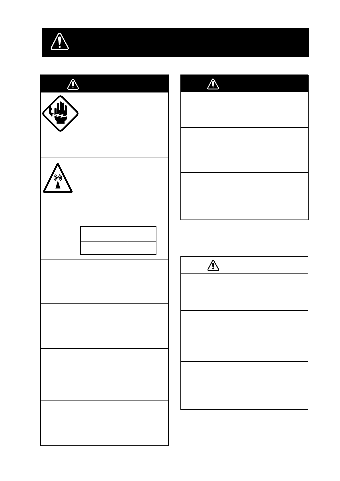
WARNING
WARNING
WARNING
Do not open the equipment.
Hazardous voltage which can
cause electrical shock, burn
or serious injury exists inside
the equipment. Only qualified
personnel should work inside
the equipment.
Hazardous microwave.
Do not approach within
60 cm of the antenna radome
when it is transmitting.
Microwave radiation can be
harmful to the human body,
particularey the eyes.
Radiation Level At
10W/m
WARNING
Do not operate the equipment with wet
hands.
Electrical shock can result.
Keep heater away from equipment.
Heat can alter equipment shape and melt
the power cord, which can cause fire or
electrical shock.
Any repair work must be done by a
licensed radio technician.
Improper repair work can cause electrical
shock or fire.
2
60 cm
Leave the equipment powered while
underway.
Distress cannot be communicated unless
the equipment is powered.
Do not disassemble or modify the
equipment.
Fire, electrical shock or serious injury can
result.
Turn off the power immediately if water
leaks into the equipment or the equipment is emitting smoke or fire.
Continued use of the equipment can cause
fire or electrical shock.
Do not place liquid-filled containers on
the top of the equipment.
Fire or electrical shock can result if a liquid
spills into the equipment.
iiiiiiiiiiiii
i
Page 4
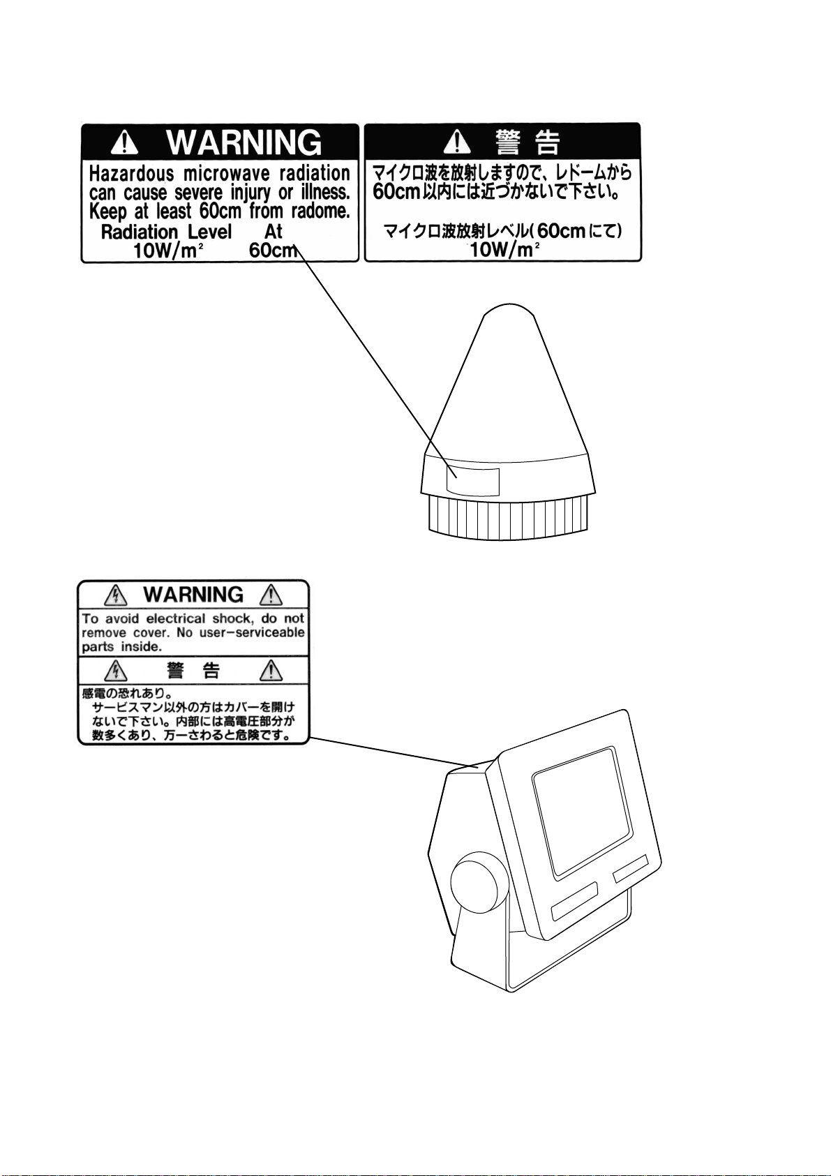
W ARNING Label attached
Name: Warning Label
Type: 16-013-2013-1
Code No.: 100-251-640
Name: Warning Label(1)
Type: 16-003-1011-0
Code No.: 100-236-230
Antenna Unit
Terminal Unit
ii
Page 5

CONTENTS
MENU TREE .....................................................................................vii
OPERATIONAL OVERVIEW ...........................................................viii
PROGRAM NUMBER........................................................................ix
FOREWORD.......................................................................................1
Introduction .............................................................................................................................. 1
Features..................................................................................................................................... 2
About This Manual ...................................................................................................................3
FELCOM 12 System Configuration......................................................................................... 4
INMARSAT -C SYSTEM ......................................................................5
Introduction .............................................................................................................................. 5
Inmarsat System Configuration ................................................................................................ 6
Communications Network........................................................................................................ 9
Types of MES ......................................................................................................................10
Peripheral Equipment ............................................................................................................. 11
Distress/Urgent Receiving Call Unit (IC-303) ....................................................................11
Distress Alert Unit (IC-302) ................................................................................................ 11
Distress Message Controller (DMC-5: Option)................................................................... 11
OPERATIONAL OVERVIEW ...........................................................1-1
The Communication Unit ......................................................................................................1-1
Self test ...............................................................................................................................1-1
When the audible alarm sounds..........................................................................................1-1
The Terminal Unit..................................................................................................................1-2
Floppy disk drive................................................................................................................1-2
Floppy disk.........................................................................................................................1-2
Printer PP-510 (optional supply) ...........................................................................................1-3
Keyboard ...............................................................................................................................1-4
Key description...................................................................................................................1-4
Shortcut key operation........................................................................................................1-6
Function Menus .....................................................................................................................1-6
Selecting menu, menu options............................................................................................1-7
Function menu description .................................................................................................1-7
Sample menu operation ......................................................................................................1-8
Display Indications ................................................................................................................1-9
Error Messages and Alerts................................................................................................... 1-11
Silencing the Audible Alarm................................................................................................1-12
Silencing the alarm by the Setup menu ............................................................................1-12
Using a Personal Computer as a Terminal Unit...................................................................1-13
PC requirements ...............................................................................................................1-13
Installing the program.......................................................................................................1-13
Contents of program disk .................................................................................................1-14
iii
Page 6

SYSTEM INITIALIZATION ...............................................................2-1
System Settings......................................................................................................................2-1
Two sets of DTEs installed.................................................................................................2-1
System setup.......................................................................................................................2-2
Terminal Setup.......................................................................................................................2-6
Login and Logout ..................................................................................................................2-7
Login ..................................................................................................................................2-8
Logout ................................................................................................................................2-9
EGC Settings .......................................................................................................................2-11
What is the EGC (Enhanced Group Call) service?...........................................................2-11
EGC setup.........................................................................................................................2-12
Programming EGC channels ............................................................................................2-15
Programming NCS Channels...............................................................................................2-16
LES List Operations ............................................................................................................2-18
Programming the LES list ................................................................................................2-18
Deleting and changing the LES list ..................................................................................2-20
Printing the LES list .........................................................................................................2-20
Station List Operations ........................................................................................................2-22
Programming the station list.............................................................................................2-22
Editing the station list.......................................................................................................2-25
Printing the station list......................................................................................................2-25
Entering Own Ship’s Position..............................................................................................2-26
Setting Directories ...............................................................................................................2-27
E-mail Service List ..............................................................................................................2-28
E-mail Setup ........................................................................................................................2-30
FILE OPERATIONS .........................................................................3-1
Preparing a Message..............................................................................................................3-1
Preparing a routine message...............................................................................................3-1
Preparing a confidential message .......................................................................................3-2
Editor menu setup...............................................................................................................3-3
Cutting and pasting text......................................................................................................3-4
Copying and pasting text ....................................................................................................3-5
Insert (with Citation) ..........................................................................................................3-6
Select All ............................................................................................................................3-6
Search and Replace.............................................................................................................3-6
Go to line ............................................................................................................................3-6
Time or Pos. ins..................................................................................................................3-6
Saving a Message ..................................................................................................................3-7
Formatting a floppy disk ....................................................................................................3-7
Saving a message................................................................................................................3-8
Opening a File .....................................................................................................................3-10
Opening a file ...................................................................................................................3-10
Switching between files....................................................................................................3-11
Opening a file where a working area is occupied.............................................................3-11
Saving a File Under a New Name .......................................................................................3-12
Printing a File ......................................................................................................................3-13
Combining Files ..................................................................................................................3-14
Deleting a File .....................................................................................................................3-14
MIME (Multipurpose Internet Mail Extensions).................................................................3-15
Rename ................................................................................................................................3-16
iv
Page 7

INMARSAT -C COMMUNICATIONS.................................................4-1
Transmitting...........................................................................................................................4-1
Code description.................................................................................................................4-1
Transmitting prepared message..........................................................................................4-2
Transmitting message stored on floppy disk (multiple address) ........................................4-9
Canceling transmission.....................................................................................................4-13
Confirming delivery status (message status list) ..............................................................4-14
Manually requesting delivery status.................................................................................4-16
The 2-digit code services..................................................................................................4-17
Inserting the destinations of a fax terminal ......................................................................4-19
Receiving .............................................................................................................................4-20
When a message is received .............................................................................................4-20
Setting the receive alarm ..................................................................................................4-21
Displaying receive messages............................................................................................4-22
Printing receive messages.................................................................................................4-23
Saving receive messages to a floppy disk ........................................................................4-24
Automatically saving receive messages ...........................................................................4-24
Deleting receive messages................................................................................................4-25
Distress/Urgent Receiving Call Unit IC-303....................................................................4-26
Display Log .........................................................................................................................4-26
Displaying and printing the display log............................................................................4-26
Automatic printing of display log.....................................................................................4-27
Display send message log or receive message log ...........................................................4-28
EGC Messages.....................................................................................................................4-28
Displaying and reprinting EGC messages........................................................................4-28
Displaying EGC closed network ID (ENID)....................................................................4-29
Receiving EGC distress or ur gent message......................................................................4-30
Tx Message Example Printout.............................................................................................4-30
DAT A REPORTING AND POLLING ................................................5-1
Data Reporting.......................................................................................................................5-1
Setting a data report............................................................................................................5-1
Setting a message report.....................................................................................................5-4
Polling....................................................................................................................................5-6
Polling command................................................................................................................5-6
Other polling command......................................................................................................5-7
Polling reception.................................................................................................................5-8
DNID (Data Network Identification).....................................................................................5-9
Displaying DNID................................................................................................................5-9
Enabling/Disabling DNID................................................................................................5-10
DISTRESS ALERT...........................................................................6-1
Preparing a Distress Alert ......................................................................................................6-1
Transmitting a Distress Alert .................................................................................................6-3
Testing Distress Button..........................................................................................................6-4
Distress Communications ......................................................................................................6-5
v
Page 8

OTHER FUNCTIONS.......................................................................7-1
Aborting an Operation ...........................................................................................................7-1
Scanning NCS........................................................................................................................7-2
Selecting EGC Receiving Channel........................................................................................7-3
Selecting NCS Channel .........................................................................................................7-4
MAINTENANCE...............................................................................8-1
Safety Information.................................................................................................................8-1
General Checking and Maintenance......................................................................................8-2
Cleaning the terminal unit and communication unit ..........................................................8-2
Checking connectors and earth terminal ............................................................................8-2
Floppy disk drive head .......................................................................................................8-2
When the power can’t be turned on (power lamp does not light) ......................................8-2
Self Tests................................................................................................................................8-3
Self test at power application (communication unit)..........................................................8-3
Testing the communication unit through the keyboard ......................................................8-3
Performance Verification (PV) Test.......................................................................................8-4
PV test sequence.................................................................................................................8-4
PV test procedure ...............................................................................................................8-5
Results of PV test ...............................................................................................................8-6
System Status Monitor...........................................................................................................8-7
Interpreting the system status monitor ...............................................................................8-8
Replacing Internal Battery.....................................................................................................8-9
Error Messages ....................................................................................................................8-10
SPECIFICATIONS.........................................................................SP-1
APPENDIX....................................................................................AP-1
International Telex/Telephone Country Code List............................................................. AP-1
International Telex Abbreviations...................................................................................... AP-9
Glossary of Acronyms ..................................................................................................... AP-10
International Telegraphy Alphabet....................................................................................AP-11
Error Messages and Alerts............................................................................................... AP-12
LES IDs List .................................................................................................................... AP-15
Digital Interface (IEC 61162-2)....................................................................................... AP-16
INDEX ............................................................................................IN-1
Declaration of conformity to type
vi
Page 9

MENU TREE
Numerals in parenthesis are page numbers.
F1: File
1: New ALT-N
2: Open ALT-O
3: Close ALT-Q
4: Save ALT-S
5: Delete ALT-D
6: Rename
7: Print ALT-P
8: Format Disk
9: MIME (Decode)
9: QUIT (PC only)
F2: Edit
1: Cut DEL
2: Copy ALT-C
3: Paste INS
4: Insert (with Citation)
5: Select All ALT-A
6: Search or Replace
7: Go to line
1: Top of Text Fn-←
2: End of Text Fn-→
3: Go to Line
8: Time or Pos. Ins
9: Change Window ALT-V
F3: Transmit
1: Transmit Message
2: Cancel
3: Request Delivery Status
F4: EGC
1: Display EGC Message
2: EGC Network ID
(3-1)
(3-10)
(3-9)
(3-12)
(3-14)
(3-16)
(3-13)
(3-7)(IB-581only)
(3-15)
(3-4)
(3-5)
(3-5)
(3-6)
(3-6)
(3-6)
(3-6)
(3-6)
(3-6)
(3-6)
(3-11)
(4-2, 4-9)
(4-13)
(4-14)
(4-28)
(4-29)
F5: Reports
1: Data Report
2: Message Report
3: Date Network ID
F6: Logs
1: Send Message Log
2: Receive Message Log
3: EGC Log
4: Log
F7: Options
1: Login
2: Logout
3: Abort
4: Select NCS
5: Ocean Region
6: Test
F8: Setup
1: Distress Alert Setup
2: System Setup
3: Editor Setup
4: Terminal Setup
5: EGC Setup
6: Auto Mode Setup
7: E-Mail Setup
8: Directories
9: Configuration
1: Station List
2: LES List
3: EGC Channel List
4: NCS Channel List
5: E-Mail Service List
(5-1)
(5-4)
(5-8)
(4-28)
(4-22)
(4-28)
(4-26)
(2-7)
(2-9)
(7-1)
(7-4)
(7-2)
(6-4, 8-3)
(6-1)
(2-2)
(3-3)
(2-1)
(2-11)
(4-21, 4-24, 4-27)
(2-30)
(2-27)
(2-22, 2-25)
(2-20, 2-18)
(2-15, 7-3)
(2-16)
(2-28)
F9: Position
F10: Stop Alarm
(2-26)
(1-1)
vii
Page 10
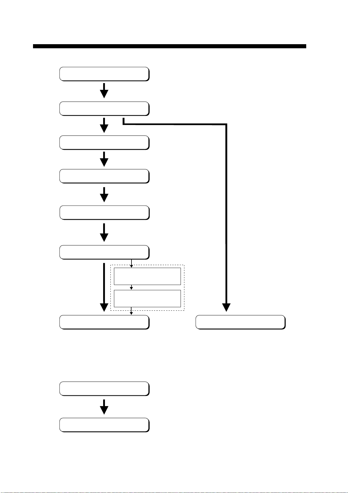
Power On
Login
System Initialization
Program LES
OPERATIONAL OVERVIEW
Program Station
Prepare Message
Saving a message
(page 3-8)
Retrieving a message
(page 3-10)
Transmitting
The FELCOM 12 should be turned on for the duration of a voyage.
Be sure to logout with Inmarsat-C system before turning off the equipment.
Receiving
viii
Logout
Power Off
Page 11

PROGRAM NUMBER
rofnosaeR.oNbuP
etaD,noitacifidoM
K-03165-EMO
CEIhtiwmrofnocotdeifidoM
2noitidE1-26116
4/2002
.oNmargorPerawtfoS
)3/8991(300-2110-5611UPC
)3/8991(300-4110-561DOMED
)4/2002(410-8110-5612UPC
)4/0002(600-6110-561LANIMRET
ix
Page 12

This page is intentionally left blank.
Page 13

Introduction
FOREWORD
FURUNO Electric Company thanks you for considering and purchasing the FELCOM 12 Inmarsat-C Mobile Earth Station. W e are confident you will discover why the FURUNO name has become synonymous with quality and reliability.
Mainly consisting of an antenna unit, a communication unit and terminal unit, the FELCOM 12 provides the full range of distress and
general communication services for mobile and fixed terrestrial subscribers in the Inmarsat-C communication network. Its compact size
permits installation where space is limited.
FURUNO designs and manufactures this equipment with much attention to operation and maintenance simplicity. However , please read
and follow the recommended procedures for operation and maintenance to get the most out of the equipment.
This manual provides a brief introduction to the Inmarsat-C system
(pages 5 thru 10). For more detailed information, however, please
refer to “Inmarsat-C Maritime User’ s Manual” published by Inmarsat.
(It is free of charge.) Below are contact points for Inmarsat.
Inmarsat-C Maritime Customer Relations Officer
Maritime Services Operations Department
International Maritime Satellite Organization (Inmarsat)
Address: 99 City Road, London EC1Y 1AX, UK
Telephone: +44 71 728 1000 (Switchboard)
Fax: +44 71 728 1192
Telex: 297201 Inmarsat G
1
Page 14

Features
¡ Conforms to the following standards: IMO A.807(19),
MSC. 68(68), Annex 4, IMO A.694(17), IEC 61097-4 (1994),
IEC 60945 (1996), IEC 61162-1 (2000)
¡E-mail facility
To transmit E-mail, register with the LES provider. E-mail
charges are calculated separately.
¡Built in Enhanced Group Call (EGC) receiver permits operation as
EGC-only receiver.
¡Communication unit accepts a wide variety of peripheral equip-
ment, Distress Message Controller (DMC), personal computer and
remote panel.
¡Connection of 2nd Data T erminating Equipment (DTE) for opera-
tion from remote location such as the bridge
¡Store-and-forward telex communication (public telex network)
¡Data reporting and Polling
¡Internal GPS receiver (option) in the communication unit provides
GPS-generated position.
¡Self test programs for maintenance
¡Terminal unit provides floppy disk drive for unlimited storage of
received and transmitted messages on floppy disks.
¡Menu driven operation
2
Page 15

About This Manual
A word about the or ganization of this manual: It is laid out in a userfriendly manner as possible. We realize a machine like this with its
many, many functions can be a little intimidating to even the experienced MES operator. This is why we have arranged this manual in a
series of sections that start at a basic level and proceed forward in
complexity in a logical manner.
The best way to acquaint yourself with the many facilities this equipment has to offer is to turn it on and try keying in the examples provided in each of the sections. In hardly no time at all you’ll be enjoying
the benefits of the Inmarsat-C system.
Inmarsat-C System This chapter explains the Inmarsat-C sys-
Operational Overview This chapter introduces basic operations.
System Initialization Read this chapter to learn how to initialize
File Operations Y ou will learn how to use the text editor in
tem.
the FELCOM 12.
this chapter, to prepare, edit and save messages.
Inmarsat-C Read this chapter to learn how to transmit
Communications and receive in the Inmarsat-C system.
Data Reporting and Polling
This chapter explains data reporting setting and polling reception.
Distress Alert This chapter tells you how to prepare and
transmit the distress alert, and conduct distress communications.
Other Functions This chapter describes how to abort op-
eration, scan NCS, and select various channels.
Maintenance The maintenance chapter presents infor-
mation for keeping the FELCOM 12 in top
operating condition.
Appendix The Appendix presents international telex
country codes, international telex abbreviations, glossary of acronyms, error messages and alerts, and international telegraphy alphabet.
3
Page 16
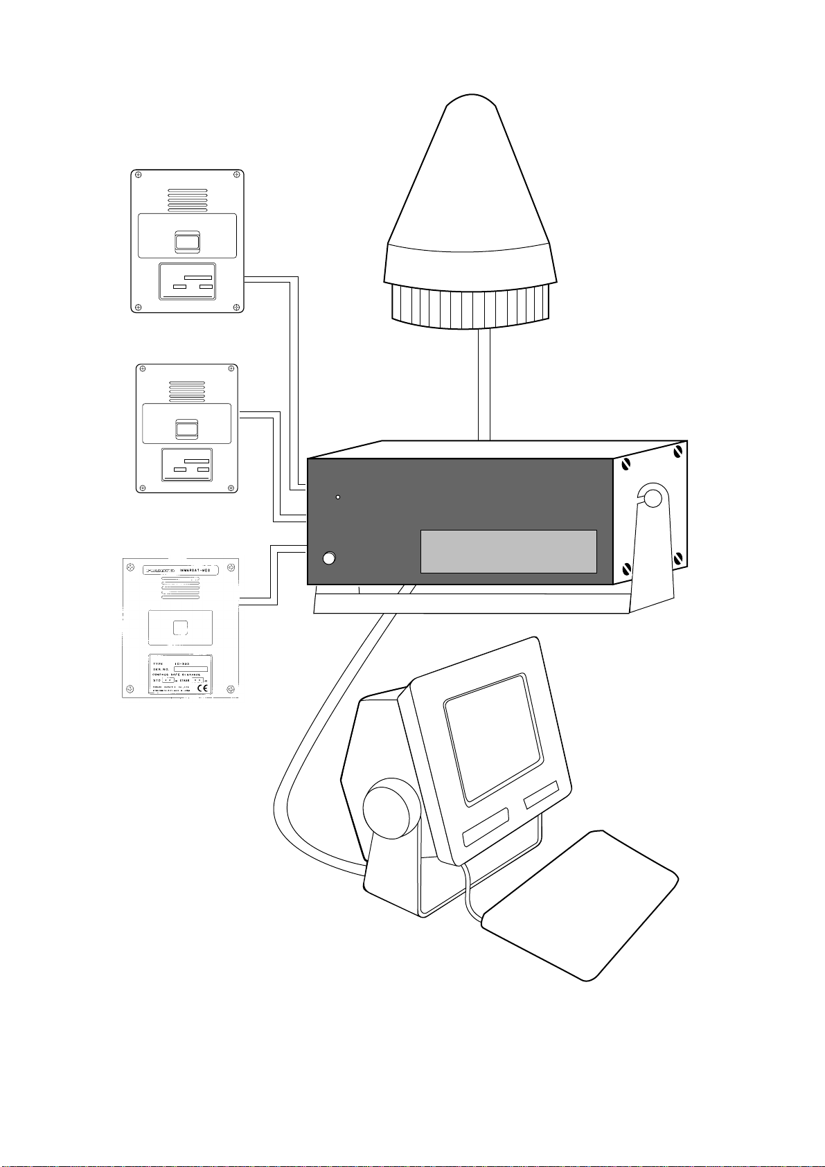
FELCOM 12 System Configuration
DISTRESS
TYPE IC-302
SEL NO.
COMPASS SAFE DISTANCE
STD M
FURUNO ELECTRIC CO., LTD
Distress Alert Unit
IC-302
DISTRESS
TYPE IC-302
SEL NO.
COMPASS SAFE DISTANCE
STD M
FURUNO ELECTRIC CO., LTD
Distress Alert Unit
IC-302
ALARM RESET
DISTRESS / URGENT
RECEIVING UNIT
Distress/Urgent
Receiving Unit
IC-303
FURUNO
POWER
Antenna Unit
INMARSAT- C MOBILE EARTH STATION
Communication Unit
4
Terminal Unit
Figure 1 FELCOM 12 system configuration
Page 17

Introduction
INMARSAT-C SYSTEM
This chapter provides an overview of the Inmarsat-C satellite communication system.
The Inmarsat-C system provides worldwide telex and data transmission and reception of written information to owners of an Inmarsat-C
transceiver or a terrestrial telex network via satellite.
Communication mode is store-and-forward telex, which means all
information sent are first stored at a LES and then delivered to designated party.
An EGC (Enhanced Group Call) receiver is built in the FELCOM 12
to receive the following types of messages, broadcast from a LES:
¡SafetyNETTM-governments and maritime authorities can use this
service to distribute maritime safety information to ships within
selected areas.
¡FleetNET
companies can use this service to transmit trade information (for
example, company news or market prices) simultaneously to a selected group of ships, to provide up-to-the-minute information.
FELCOM 12 allows you to make distress calls which are given immediate priority over all other calls, and are automatically routed to a
land-based Rescue Co-ordination Centre (RCC).
Besides its primary application of ship-shore, shore-ship or ship-ship
communications, the Inmarsat-C service has also proved beneficial
to trucking firms who have found it indispensable for communicating with their vehicles. In this manual, however, we will concentrate
on ship applications, the main application.
TM
-commercial subscription organizations or shipping
5
Page 18
Inmarsat System Configuration
6
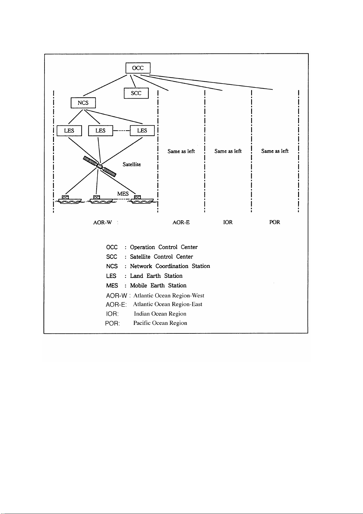
Figure 2 Inmarsat-C satellite communication system
Page 19

The Inmarsat-C system consists of the Operation Control Center
(OCC), Satellite Control Centers (SCC), Network Coordination Stations (NCS), Land Earth Stations (LES) and Mobile Earth Stations
(MES). The OCC, located at Inmarsat’s London headquarters, coordinates a wide range of activities in the Inmarsat system, including
commissioning of mobile earth stations.
The Inmarsat-C system divides the world into four regions and each
region is covered by its own satellite.
Table 1 Inmarsat system satellites
Region Satellite Satellite Position
AOR-West Inmarsat-2, F4 54.0°W
AOR-East Inmarsat-2, F2 15.5°W
IOR Inmarsat-2, F1 64.5°E
POR Inmarsat-2, F3 178.0°E
In each region there is one NCS and several LESs. The NCS keeps
track of all Inmarsat-C transceivers in its region and broadcasts information such as navigational warnings, weather reports and news.
The LES provides the link between the MES and the terrestrial telecommunications networks via satellite.
7
Page 20
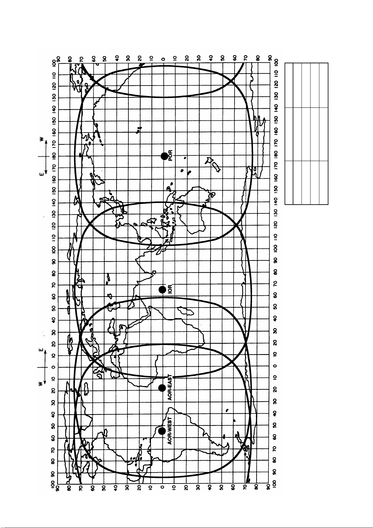
Figure 3 Coverage area of satellites
AREA
SATELLITE NAME
POSITION
POR
INMARSAT-2, F3
178° E
IOR
INMARSAT-2, F1
64.5° E
AOR-EAST
INMARSAT-2, F2
15.5° W
AOR-WEST
INMARSAT-2, F4
54.0° W
8
Page 21
Communications Network
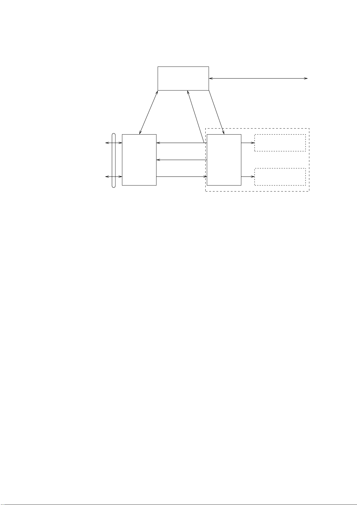
Figure 4 shows the Inmarsat-C communications network.
Data
Communications
Network
Telex Network
Terrestrial
Communications
Network
NCS/LES
Signaling Link
Land Earth
Station
(LES)
Network
Coordination
Station (NCS)
MES Signaling
Channel
MES Message
Channel
LES TDM
Channel
NCS/NCS Signaling Link
NCS Common Channel
Data Circuit
Terminating
Equipment
(DCE)
Figure 4 Inmarsat-C communications network
Mobile Earth
Station (MES)
Data Terminal
Equipment (DTE)
Enhanced Group
Calling (EGC) Receiver
NCS common channel The NCS has two major functions:
1) T ransmitting information on a common channel.
2) T ransmitting EGC messages to MESs.
NCS/LES signalling link This is the link between NCS and all
LESs in its region. All EGC messages
pass through this link.
LES TDM channel This channel carries the circuit control
signal for MES and transmits messages
from LES to MES.
MES message channel This channel carries messages from
MES to LES.
MES signaling channel This channel transmits requests, distress
alerts, data reports, etc. In addition, it
carries login and logout from MES to
NCS.
NCS/NCS signaling link This is the link between NCSs. It ex-
changes data between MESs operating
in different ocean regions.
9
Page 22

MES interface The MES consists of the Data Circuit
T erminating Equipment (DCE) and the
Data Terminal Equipment (DTE). The
DCE consists of the antenna unit and
the communication unit. And the DTE
consists of the terminal unit (or a PC),
keyboard and printer.
Terrestrial network The major functions of the LESs are:
interface
1) Telex store-and-forward conversion
2) Handling EGC messages
3) Handling distress alerts
4) Data Reporting and Polling
Types of MES
There are three types of MES: class 1, class 2 and class 3. The
FELCOM 12 is a class 2 MES.
Class 1 1) Transmits messages to LES
2) Receives messages from LES
Class 2 1) The functions of class 1 plus opera-
tion as an EGC receiver when not
transmitting or receiving.
2) EGC-only receiver
Class 3 The function of class 1 plus simulta-
neous operation as a EGC-only receiver .
10
Page 23
Peripheral Equipment
The following equipment can be additionally connected to the
FELCOM 12.
Distress/Urgent Receiving Unit (IC-303)
The IC-303 releases an audible alarm and blinks the lamp when distress message is received. (Refer to page 4-26 for further details.)
When an EGC distress or urgent message is received, with an aural
alarm and blinking lamp.
Distress Alert Unit (IC-302)
The IC-302 enables transmission of the distress alert from a remote
location; for example, ship’s bridge. (Refer to page 6-3 for more details.)
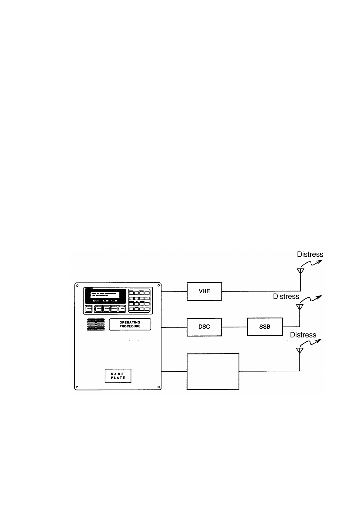
Distress Message Controller (DMC-5:Option)
The DMC provides for transmission and monitoring of the distress
alert. For further details, refer to the operator’s manual of the DMC-
5.
Inmarsat C
Distress Message Controller DMC-5
Figure 5 Distress Message Controller system
11
Page 24

This page is intentionally left blank.
Page 25
OPERATIONAL OVERVIEW
This chapter provides an overview of the FELCOM 12 system.
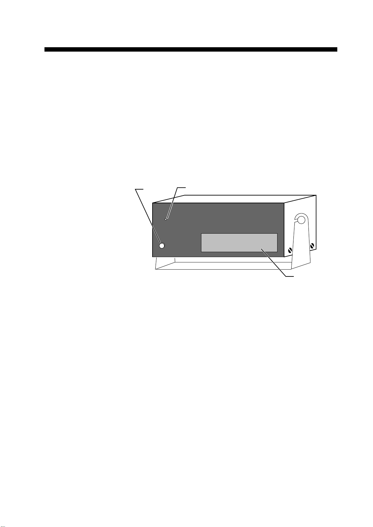
The Communication Unit
The communication unit is the heart of the FELCOM 12 system, transmitting and receiving messages and alerting you to equipment fault.
On its front panel you should see the POWER switch and POWER
lamp. Normally, the power is left on while underway.
POWER
Switch
FURUNO
POWER
POWER
lamp
INMARSAT- C MOBILE EARTH STATION
NAME PLATE
Figure 1-1 Communication unit IC-212
Self test
When the communication unit is turned on it conducts a series of
self-tests to check itself for proper operation.
When the audible alarm sounds
The audible alarm sounds in the following circumstances:
1) EGC distress or urgent message is received. (T o silence the alarm,
press [ESC] followed by [F10].)
2) During the interval between the transmission of the distress alert
(by own vessel) and the receiving of the distress acknowledge signal from LES. (The alarm automatically stops when your ship
recives the distress acknowledge signal.)
3) The system status monitor detects equipment fault. (T o silence the
alarm, press any key.)
The audible alarm sounds and the terminal unit displays which alarm
is sounding.
1-1
Page 26
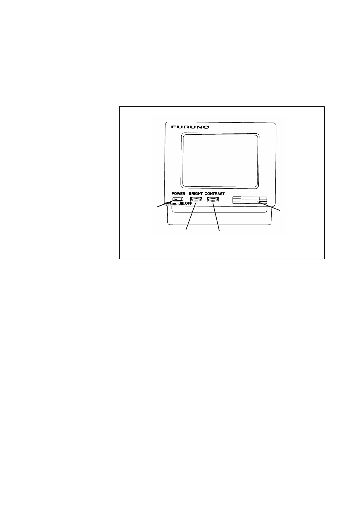
The Terminal Unit
Power switch
Floppy disk drive
BRIGHT
control
CONTRAST
control
The DTE may consist of IB-581 or IBM compatible pc. All operations are carried out from the terminal unit, through an easy-to-understand menu system. For personal computer connection a system
disk (supplied) is required to boot up the computer. Opetarion by a
computer is the same as with the terminal unit except when turning
on the power.
Figure 1-2 Terminal unit IB-581
To turn on/off the unit, press the POWER switch.
Controls for adjustment of screen brilliance and contrast are to the
right of the POWER switch.
Floppy disk drive
The terminal unit provides a floppy disk drive for storing transmitted
and received messages on floppy disks.
Floppy disk
The floppy disk used with the system is a standard 3.5” floppy disk.
Always leave a floppy disk inserted to save incoming messages.
Terminal unit cannot print file from a floppy disk when there is not
enough space remaining on the disk. In this case, replace disk with
formatted disk.
1-2
Page 27
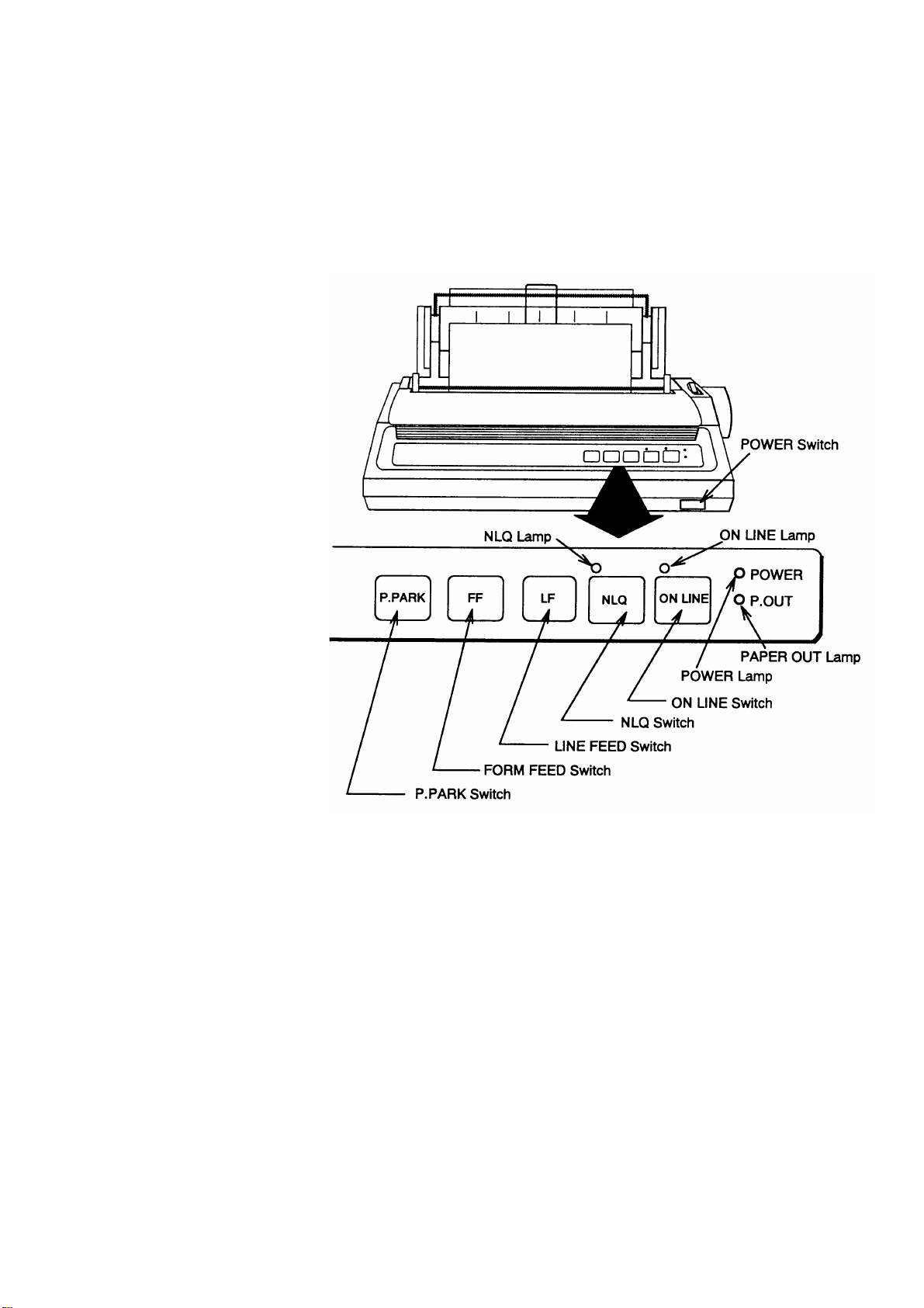
Printer PP-510 (optional supply)
The printer prints transmitted and received messages. The POWER
switch is on the right side of the unit. A lamp on the switch lights
when the power is on. If the paper is set correctly the ON LINE lamp
also lights. When both these lamps are lit the printer is ready to print
information received from the terminal unit. For further details, refer
to the operator's manual of the PP-510.
Figure 1-3 Printer PP-510
1-3
Page 28

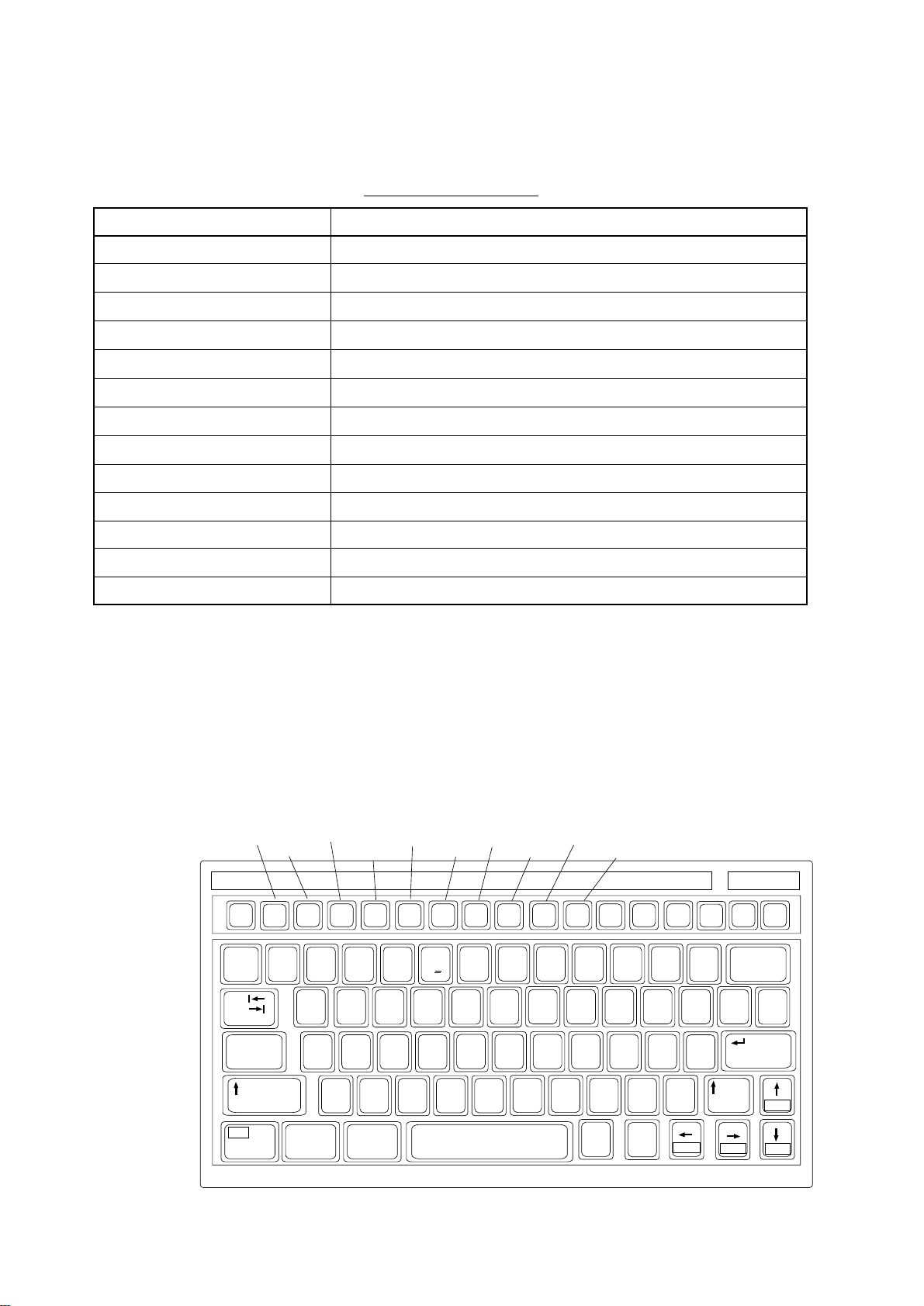
Keyboard
The FELCOM 12 is almost 100% keyboard controlled. Operation is
simplified by the use of menus which you access by pressing function keys, numbered F1-F10 at the top of the keyboard. Figure 1-4
shows keyboard layout.
Esc
~
`
Tab
Caps Lock
Fn
F1
F2 F3
2
1
QWERTYUIOP
ASDF GHJ KL:+;"
Ctrl Alt
F4
F5 F6
%
$#@!
345
ZXCVBNM<> ?/
F7
^&
C
67890 -=
F8
F9 F10
*
456
123
Num
Lock
(
9*87
0Shift
,
Alt
Figure 1-4 Keyboard
Key description
Esc Cancels key input and returns to previous
display screen.
Prt Sc
SysRq
.
Ctrl
Scroll
Lock
_+)
{}\|
[
/
Home
Pause
Break
'
Insert Delete
Backspace
]
Enter
Shift
PgUp
End PgDn
F1-F10 These are the function keys. They select
menus.
Backspace Deletes the character to the left of the cur-
sor.
Insert Works the same as PASTE function. See
page 3-5.
Delete Deletes the character on the cursor.
Home Moves the cursor to the top of a message
being edited.
End Moves the cursor to the bottom of a mes-
sage being edited.
PgUp Goes to the previous page of the edit screen.
PgDn Goes to the next page of the edit screen.
[/], [/], [,], [/] Control the cursor.
Enter Registers key input.
1-4
Page 29

Shift Selects upper or lower case letters. Press and
hold down the key to get upper case letters.
Note that only upper case letters are used in
telex.
Alt Executes the shortcut key operation when
combined with an alphabet key.
Space Bar Inserts a space. In addition, it displays file
list, partial view of a file, etc. depending on
menu.
Caps Lock Turns upper case letter input on or off. CAPS
appears on the display when the keyboard
is set for upper case letter input.
Tab Inserts horizontal tab characters. The num-
ber of tab characters the key can insert per
line of text can be programmed for two, four
or eight tabs.
Ctrl W orks in combination with alphabet keys as
follows:
Ctrl key shortcut keys
]M[+lrtC.retnEsaemaS
]H[+lrtC.ecapSkcaBsaemaS
]I[+lrtC.baTsaemaS
]V[+lrtCtresnI+etirwrevOsaemaS
FN Combined with an arrow Key, it scrolls
screen(
,/),or shifts cursor (,, /).
/
Num Lock Turns numeric input on or off. Note that you
cannot enter alphabet when the Num LED
is its.
Note1: In telex, lower case, #, &, *, $ or % are not used. A full list of
characters usable in telex appears on page A-11 in the Appendix.
Note2: C (Euro mark) on
%
key is not used.
C
5
1-5
Page 30
Shortcut key operation
The FELCOM 12 provides the keyboard shortcuts shown below for
commonly used functions.
Table 1-2 Shortcut keys
Short Cut key
ALT+N
ALT+O
ALT+Q
ALT+D
ALT+S
ALT+P
ALT+X
DELETE
ALT+C
INSERT
Fn+b (Home)
Fn+a (End)
ALT+V
Operation
Same as NEW in File menu
Same as OPEN in File menu
Same as CLOSE in File menu
Same as DELETE in File menu
Same as SAVE in File menu
Same as PRINT in File menu
Same as UNDO
Same as CUT in Edit menu
Same as COPY in Edit menu
Same as PASTE in Edit menu
Same as Top of Text in Edit/Go to line menu
Same as End of Text in Edit/Go to line menu
Same as CHANGE WINDOW in Edit menu
Function Menus
File
Edit
Esc
F1
~
`
1
Tab
Caps Lock
Fn
The function menus, which you access by pressing the function keys
(F1-F10) at the top of the keyboard, control most operations of this
unit.
Transmit
F2 F3
2
QWERTYUIOP
ASDF GHJ KL:+;"
ZXCVBNM<>?/
Ctrl Alt
Reports
EGC
F4
F5 F6
34
Options
Logs
F7
F8
^&$#@!
%
C
5
67890 - =
Position
Setup
F9 F10
*
(
456
123
0Shift
Alt
StopAlarm
Prt Sc
Num
Lock
SysRq
9*87
,
.
Ctrl
Scroll
Lock
_+)
{}\|
[
/
Home
Pause
Break
'
Insert Delete
Backspace
]
Enter
Shift
End PgDn
PgUp
1-6
Page 31

Selecting menu, menu options
Press appropriate function key to select a menu. For example, press
[F1] to select the File menu.
File Edit Transmit EGC Reports Logs Options Setup Position StopAlarm
File
1. New
2. Open
3. Close
4. Save
5. Delete
6. Rename
7. Print
8. Format Disk
9. MIME (Decode)
You may select menu options with the arrow keys (pressing [Enter]
after making selection) or appropriate numeric key. As the cursor
moves down through a menu, when usings the arrow keys, each menu
option, initially shown as white on black, reverses to black on white.
This highlighting indicates the item is available for selection. In Figure 1-6, for example, “New” is available for selection.
ALT-N
ALT-O
ALT-Q
ALT-S
ALT-D
ALT-P
Figure 1-6 File menu
Function menu description
Table 1-3 Function menu description
uneMnoitpircseD
eliF.selifsessecorP
tidE.seitilicafgnitidetxetsedivorP
timsnarT.segassemstimsnarT
CGE.seitilicafegassemCGEpusteS
stropeR.noitcnufgnitroperatadpusteS
sgoL.sgolegassemeviecerdnadnessyalpsiD
snoitpO.seitilicafgnitset,tuogol,nigoL
puteS.metsysehtpusteS
noitisoP.noitisops'pihsruoysretnE
mralApotS.rezzubsecneliS
1-7
Page 32

Sample menu operation
For example, you want to display a transmitted message. All operations begin from the standby display.
File Edit Transmit EGC Reports Logs Options Setup Position StopAlarm
Date
Time
Position
Waypoint
Course
Speed
Current NCS
Current Channel
Current TDM
MES Status
GPS Status
DCE Memory
Current State: IDLE
DCE Ver **
97-08-04
01:32 (UTC)
LAT
LON
LAT
LON
DEG
KTS
344 (IOR) LOGOUT
NCS CC
NCS CC
Idle
****
32818 Bytes free
SYNC ( NCS )
NCS: IOR LOGOUT
BBER
C/N
Send level
RxIF AGC Level
REF Offset Freq
Synthe 1st-1 Local
1st-2 Local
RX2nd Local
Antenna Power Supply
Water Temperature
Water Current
Direction
Speed
Depth
97-08-04 01:32 (UTC)
Figure 1-7 Standby display
Press [F6] to display the Logs menu.
File Edit Transmit EGC Reports Logs Options Setup Position StopAlarm
Log
1. Send Message Log
2. Receive Message Log
3. EGC Log
4. Log
000
OK ( 36dB)
OK ( 0)
OK (135)
OK ( 0Hz)
OK
OK
OK
OK
DEG
DEG
KTS
Figure 1-8 Logs menu
Press [1] to display the send message log.
File Edit Transmit EGC Reports Logs Options Setup Position StopAlarm
Log
1. Send Message Log
2. Receive Message Log
No. Message File Station LES Priority Send Status Delivery
Send Message Log
Figure 1-9 Send message log
Select the message you want to display by pressing [
lowed by [Enter].
] or [/] fol-
/
1-8
Page 33

Display Indications
The display is divided in three sections:
1) The menu area
2) The working area
3) The operating status area
File Edit Transmit EGC Reports Logs Options Setup Position StopAlarm
(1) (2)
2 WORKING AREA
(3)
(4)
(4)
(5)
(6) (7)
(8)
(9)
(10)
(10)
Figure 1-10 Location of display indications
Below are indications and their meanings.
1 Function
Menu
3 Operating
Status
(1) Distress alert information
No display (no distress alert)
Distress Alert Activated
Distress Alert T est Activated
Distress Alert Acknowledge Received
Distress Message Call Activated
Distress Message Call Acknowledged
(2) Communication network mode
No display Normal operation
Restoration Mode Problem at NCS.
(blinking)
Restoration Mode Previously designated LES is trans-
(reverse indication) mitting the NCS common channel
signal.
1-9
Page 34

(3) Communication unit status
Idle Idle (awaiting receiving, awaiting trans-
mitting)
Idle (pending) Awaiting reply from LES
Sending During message transmission
Receiving During receiving
Login Logging in with NCS
Logout Logging out with NCS
Distress Alert When own vessel is transmitting the
distress alert
Data Report During transmission of data report
Testing PV testing
Test Setup Requesting PV testing
Scanning NCS scanning
EGC RECEIVER EGC-only receiver operation
(reverse indication)
Delivery Status Req. When transmitting delivery status re-
quest
Forced Clearing When stopping receiving, transmitting,
or scanning
(4) Communication unit remarks and DCE
version number
This area provides remarks about communication unit status.
(5) Frame synchronization
Blank When changing channel, or during
transmission
SYNC (NCS) Synchronizing with NCS
SYNC (LES) Synchronizing with LES
UNSYNC Out of synchronization
Retuning Synchronizing with NCS or LES
1-10
(6) Ocean region receiving
No display Out of synch with satellite
AOR-W Atlantic Ocean Region-West
AOR-E Atlantic Ocean Region-East
IOR Indian Ocean Region
POR Pacific Ocean Region
Page 35

(7) Logging status
LOGOUT Logged out with ocean region
LOGIN Logged in with ocean region
LOGIN (blinking) Logging in with ocean region
(8) Other information
No display No receive message in memory, or
printer is operating.
REC. MESSAGE EXISTS Displayed when a routine message has
(blinking) not been printed, or a confidential mes-
sage is received.
DA TA REPORT When data reporting is activated.
(Reverse indication)
(9) Date and time display
The date (set at system setting) and time (set by satellite) appear.
Time is updated every minute (with navigator connection).
(10) Ship’s position
Ship’s position (automatic or manual input) appears here.
Error Messages and Alerts
The terminal unit displays error messages and alerts to call your attention to misoperation, failed operation and system error. A list of
error messages and alerts appears on pages A-12 through A-14 in the
Appendix. To erase an error or an alert, press [Esc].
File Edit Transmit EGC Reports Logs Options Setup Position StopAlarm
Log
1. Send Message Log
2. Receive Message Log
No. Message File Station LES Priority Send Status Delivery
No Message
Send Message Log
CAUTION
<Press ESC key to coninue>
Figure 1-11 Location of error messages and alerts
1-11
Page 36

Silencing the Audible Alarm
Some error messages and alerts are accompanied by the audible alarm.
This alarm can be silenced, in most instances, by pressing any key . If
the alarm cannot be silenced in that manner, go to the Setup menu to
silence it. Note that the distress alert alarm transmitted by own ship
cannot be silenced by either method; it automatically stops when you
receive the distress acknowledge signal from LES.
Silencing the alarm by the Setup menu
1. Press [F8] to display the Setup menu.
File Edit Transmit EGC Reports Logs Options Setup Position StopAlarm
Setup
1. Distress Alert Setup
2. System Setup
3. Editor Setup
4. Terminal Setup
5. EGC Setup
6. Auto Mode Setup
7. E-Mail Setup
8. Directories
9. Configuration
Current State: IDLE
DCE Ver **
SYNC ( NCS )
NCS: IOR LOGOUT
Figure 1-12 Setup menu
2. Press [6] to display the Auto Mode Setup menu.
/
3. Press [
] key to go to the Receive Alarm line.
4. Press [Enter] to open the selection window.
Setup
Auto Mode Setup
Auto Log Print
Receive Alarm
Auto Telex Msg Save
Auto EGC Msg Save
7. E-Mail Setup
8. Directories
9. Configuration
ON
OFF
Figure 1-13 Auto mode setup menu
97-08-04 01:42 (UTC)
1-12
Page 37

File Edit Transmit EGC Reports Logs Options Setup Position StopAlarm
Set
Setup
1. Distress Alert Setup
2. System Setup
3. Editor Setup
4. Terminal Setup
5. EGC Setup
6. Auto Mode Setup
7. E-Mail Setup
8. Directories
9. Configuration
Current State: IDLE
DCE Ver **
SYNC ( NCS )
NCS: IOR LOGOUT
Figure 1-12 Setup menu
2. Press [6] to display the Auto Mode Setup menu.
3. Press [/] key to go to the Receive Alarm line.
4. Press [Enter] to open the selection window.
up
Auto Mode Setup
Auto Log Print
Receive Alarm
Auto Telex Msg Save
Auto EGC Msg Save
Data Report & Polling Print
7. E-Mail Setup
8. Directories
9. Configuration
OFF
ON
ON
ON
OFF
OFF
ON
Figure 1-13 Auto mode setup menu
5. Press [/] to select OFF.
97-08-04 01:42 (UTC)
Note: To silence the audible alarm given to an EGC distress or
urgent message from Distress Alert Unit (IC-302), follow
the above procedure. DO NOT press the DISTRESS button
on the IC-302 to silence the alarm; you will transmit own
ship’s distress alert.
6. Press [Enter] to close the selection window.
7. Press [Esc] twice.
1-13
Page 38

Contents of program disk
READ.ME: Instructions for installation of software
IBINST.BAT: English software for IB-581
IBRINST.BAT: Russian software for IB-581
PCINST.BAT: English software for PC
PCRINST.BAT: Russian software for PC
INSTALL.BAT: Program start up
FELCOM12.EXE: Terminal software
ENGLISH.DAT: English text definition file
RUSSIAN.DAT: Russian text definition file
ENH_FONT.EXE: Russian driver
DTE.DAT: Terminal software definition file (for PC)
DTE.B: Terminal software definition file (for IB-581)
LES.DAT: LES list
FORMAT.COM: Format disk
1-14
Page 39

System Settings
SYSTEM INITIALIZATION
This chapter provides the information necessary for initializing the
FELCOM 12. Once the FELCOM 12 is initialized you need do no
more than press a few keys to get fully automatic transmission and
reception.
Inmarsat assigns each MES an Inmarsat Mobile Number (IMN). The
IMN has already been entered into the FELCOM 12.
Two sets of DTEs installed
The communication unit provides two sets of connectors (DTE1, main;
DTE2, 2nd) for connection of two DTEs. It is preset at the factory for
connection with one DTE (main DTE). Main DTE is available to set
the menu.
1. Press [F8] to select the Setup menu.
File Edit Transmit EGC Reports Logs Options Setup Position StopAlarm
Setup
1. Distress Alert Setup
2. System Setup
3. Editor Setup
4. Terminal Setup
5. EGC Setup
6. Auto Mode Setup
7. E-Mail Setup
8. Directories
9. Configuration
Current State: IDLE
DCE Ver **
SYNC ( NCS )
NCS: IOR LOGOUT
97-08-04 01:50 (UTC)
Figure 2-1 Setup menu
Menu Items which cannot be set on 2nd DTE (Sub DTE )are shown
in gray.
2-1
Page 40

System setup
The System Setup menu provides for input of date, time, operating
mode, and port function.
1. Press [F8] to select the Setup menu.
File Edit Transmit EGC Reports Logs Options Setup Position StopAlarm
Setup
1. Distress Alert Setup
2. System Setup
3. Editor Setup
4. Terminal Setup
5. EGC Setup
6. Auto Mode Setup
7. E-Mail Setup
8. Directories
9. Configuration
Figure 2-4 Setup menu
2. Press [2] to display the System Setup screen.
Note: If the communication unit is off or its interconnection cable
has loosened or is damaged, “No response fr om communication unit.” appears.
Setup
System Setup
System Date & Time
Preferred NCS
MES Operation Mode
Nav Port
Active Port
Message Output Port
EGC Output Port
9. Configuration
01:53 97-08-04 (YY-MM-DD)
IOR
INMARSAT-C
OFF
DTE1
DTE1
DTE1
Figure 2-5 System setup menu
3. Press [Enter] to open the date window.
Setup
System Setup
01:53 97-08-04
System Date & Time
Preferred NCS
MES Operation Mode
Nav Port
Active Port
Message Output Port
EGC Output Port
9. Configuration
01:53 97-08-04 (YY-DD)
INMARSAT-C
OFF
ALL
DTE1
DTE1
Figure 2-6 System setup menu, system date & time
2-2
4. Enter the date.
5. Press [Enter] to close the window.
/
6. Press [
] to advance the cursor to the Preferred NCS line.
Note: Date cannot be entered in the FFA version.
Page 41

7. Press [Enter] to open the selection window.
Setup
System Setup
System Date & Time
Preferred NCS
MES Operation Mode
Nav Port
Active Port
Message Output Port
EGC Output Port
9. Configuration
01:53 97-08-04 (YY-MM-DD)
Auto
IOR
AOR (WEST)
INMARSAT-C
AOR (EAST)
OFF
POR
DTE1
IOR
DTE1
Figure 2-7 System setup menu, preferred NCS
8. Select appropriate NCS (Auto, AOR-West, AOR-East, POR or
IOR) by arrow keys. The FELCOM 12 will search for that NCS
signal each time it is turned on. The Auto setting searches all NCS
signals to find the most suitable NCS; thus, scanning can take
quite some time. (For reference, the coverage range of each satellite is shown in the figure on page 8.)
If you want to change the NCS channel temporarily, refer to “Selecting NCS channel” on page 7-4.
9. Press [Enter] to close the selection window.
/
10.Press [
] to advance the cursor to the MES Operation Mode line.
11.Press [Enter] to open the selection window.
Setup
System Setup
System Date & Time
Preferred NCS
MES Operation Mode
Nav Port
Active Port
Message Output Port
EGC Output Port
9. Configuration
01:53 97-08-04 (YY-MM-DD)
IOR
INMARSAT-C
INMARSAT-C
OFF
EGC
DTE1
DTE1
Figure 2-8 System setup menu, MES operation mode
12.Select operating mode, either Inmarsat C or EGC. The Inmarsat
C setting provides telex communications and operates as an EGC
receiver when not transmitting or receiving. The EGC setting enables EGC-only receiver operation. In this case EGC RECEIVER
appears in reverse indication at the bottom of the screen.
13.Press [Enter] to close the selection window.
/
14.Press [
] to advance the cursor to the Nav Port line.
Note: The MES Operation Mode in the FFA version cannot
be set to other than“Inmarsat C.”
2-3
Page 42

15.Press [Enter] to open the selection window.
Setup
System Setup
System Date & Time
Preferred NCS
MES Operation Mode
Nav Port
Active Port
Message Output Port
EGC Output Port
9. Configuration
01:53 97-08-04 (YY-MM-DD)
IOR
INMARSAT-C
DTE1OFF
OFF
DTE1
EXT
DTE1
INT
Figure 2-9 System setup menu, nav port
16.Select the navigation device which is interfaced to the
FELCOM 12.
OFF: No connection
EXT: Select this setting when external navigation device is
connected. The FELCOM 12 automatically selects ship’s
position information in the order of GPS, LC, and
DECCA.
INT: Internal GPS board provides position data.
Note: The Nav Port setting in the FFA version cannot be set to
other “INT.”
Note: If there is no navigation equipment connection (Nav Port
setting is “OFF”), you should input dead reckoning position in the Position menu. Refer to page 2-26.
17.Press [Enter] to close the selection window.
/
18. Press [
] to advance the cursor to the Active Port line.
19. Press [Enter] to open the selection window.
Setup
System Setup
System Date & Time
Preferred NCS
MES Operation Mode
Nav Port
Active Port
Message Output Port
EGC Output Port
9. Configuration
01:53 97-08-04 (YY-MM-DD)
IOR
INMARSAT-C
OFF
DTE1
DTE1
ALL
DTE1
Figure 2-10 System setup menu, active port
2-4
20. Select active port (DTE); “DTE1” or “ALL”.
DTE1: Only DTE1 is active.
ALL: DTE1, DTE2 and PC/DATA are active.
21. Press [Enter] to close the selection window.
/
22.Press [
] to send the cursor to the Message Output Port line.
Page 43

23.Press [Enter] to open the selection window.
Setup
System Setup
System Date & Time
Preferred NCS
MES Operation Mode
Active Port
Nav Port
Message Output Port
EGC Output Port
9. Configuration
01:53 97-08-04 (YY-MM-DD)
IOR
INMARSAT-C
DTE1
OFF
DTE1
DTE1
DTE2
PC/DATA
AUTO
Figure 2-11 System setup menu, message output port
24.Select the DTE where you want to store receive messages.
DTE1: All receive messages are routed to the main DTE
(connected to DTE1 on the communication unit)
regardless of sub address.
DTE2: All receive messages are routed to the 2nd DTE
(connected to DTE2 on the communication unit)
regardless of sub address.
PC/DATA: All receive messages are routed to the PC/DATA
(connected to PC/DA T A on the communication unit)
regardless of sub address (not used).
AUTO: Select to route messages with sub address 000 to
the main DTE, and messages with the sub address
of the 2nd DTE to the 2nd DTE. All other messages are routed to the main DTE.
Note: Do not select DTE2 or Auto when there is no DTE con-
nected to the DTE2 port; messages cannot be read from
the communications unit.
25.Press [Enter] to close the selection window.
/
26.Press [
] to advance the cursor to the EGC Output Port line.
27.Press [Enter] to open the selection window.
Setup
System Setup
01:53 97-08-04 (YY-MM-DD)
IOR
INMARSAT-C
OFF
DTE1
DTE1
DTE1
DTE1+DTE2
System Date & Time
Preferred NCS
MES Operation Mode
Nav Port
Active Port
Message Output Port
EGC Output Port
9. Configuration
Figure 2-12 System setup menu, EGC output port
28.Select the DTE where you want to store receive EGC messages;
DTE1, DTE2 or PC/DATA.
29.Press [Enter] to close the selection window.
2-5
Page 44

Terminal Setup
30.Press [Esc] to open the update window.
Setup
System Setup
System Date & Time
Preferred NCS
MES Operation Mode
Nav Port
Active Port
Message Output Port
EGC Output Port
9. Configuration
01:53 97-08-04 (YY-MM-DD)
IOR
INMARSAT-C
OFF
DTE1
DTE1
DTE1
Update
Yes No
Figure 2-13 System setup menu, update
31.Press [Enter] to select “Yes”.
32.Press [Esc] to register all system setup settings and return to the
standby display.
Terminal Setup menu provide for date display format,screen saver
and display mode.
1. Press [F8] to select the Setup menu.
2. Press [4] to display the Terminal Setup screen.
Terminal Setup
Date Disp. Form
Screen Saver
Display Mode
YY-MM-DD
ON
Normal Mode
Figure 2-14 Terminal Set up menu.
3. Press [Enter] to open the selection window.
4. Select date display format “YY-MM-DD(year-month-day)”,
“ MMM-DD-YY(month-day-year )” or “ DD-MMM-YY(day month -year)”.
5. Press [Enter] to close the selection window.
/
6. Press [
] to advance the cursor to the Screen Saver line.
7. Press [Enter] to open the selection window.
8. Select “ON” or “OFF”.
2-6
9. Press [Enter] to close the selection window.
10. Press [/] to advance the cursor to the Display Mode line.
11. Press [Enter] to open the selection window.
Page 45

Login and Logout
12. Select “Normal Mode” or “Reverse Mode”.
Normal Mode displays black characters on white
backgrund.
Reverse Mode displays white characters on black
backgrund.
13. Press [Enter] to close the selection window.
14 Press [Esc] to return to the standby display.
Each time the DTE and communication unit are turned on register
your vessel with the Inmarsat C system, to enable communications
between your vessel and LES. This is called login. The first time you
login you must do it manually; thereafter the NCS does it for you
automatically, even when you move to another ocean region.
Note that the distress alert can be transmitted and EGC messages
received regardless of whether you are logged in or not.
If you will not be using the FELCOM 12 for a prolonged period
you should logout from the Inmarsat C system, before turning
off the power to the communication unit. The Inmarsat C system
will then register you as inactive, notifying anyone trying to call you
that you are currently unavailable. If you do not log out before turning off the power , the LES may attempt to send a message to you.
may charge your correspondent, even if you never receive the
message.
Note: The communication unit should be idle (“Current State: IDLE”
appears at the bottom of the screen) to login and logout.
Note: When the FF A version is active, vessel is automatically logged
in when the power is turned on.
It
2-7
Page 46

Login
Yes
1. Confirm that “SYNC (NCS)” appears at the bottom of the screen.
2. Press [F7] to display the Options menu.
File Edit Transmit EGC Reports Logs Options Setup Position StopAlarm
Options
1. Login
2. Logout
3. Abort
4. Select NCS
5. Ocean Region
6. Test
Current State: IDLE
DCE Ver **
SYNC ( NCS )
NCS: IOR LOGOUT
97-08-04 02:01 (UTC)
Figure 2-15 Options menu
3. Press [1] to display the Login screen.
Options
Login
Start
Yes
No
Figure 2-16 Login screen
Note: The communication unit must be idle to login. When it is
not idle, “Communication Unit is not IDLE now. Cannot
start login.” appears. Pr ess any key to return to the standby
display. Wait until the communication unit becomes idle.
4. Press [Enter] to start login.
2-8
Page 47

5. LOGIN begins and the screen should now look something like
Figure 2-17. The indication LOGIN appears in blinking reverse
video.
File Edit Transmit EGC Reports Logs Options Setup Position StopAlarm
Options
Login
Starting Login Process.
Press any key to escape.
Current State: LOGIN
CALLING
DCE Ver **
LOGIN replaces IDLE.
SYNC ( NCS )
NCS: IOR LOGIN
Blinking during login
97-08-04 02:02 (UTC)
LAT:
LON:
Figure 2-17 Appearance of display screen during login
6. When login is completed, “Successful login” appears. The communication unit goes into Idle state, LOGIN stops blinking and
the ocean region you logged in with appears on the screen.
7. Press any key to return to the standby display.
Logout
1. Press [F7] to display the Options menu.
2. Press [2] to display the logout screen.
Note: The communication unit must be idle to logout. When it is
not idle, “Communication Unit is not IDLE now. Cannot
start logout.” appears. Pr ess any key to return to the standby
display. Wait until the communication unit becomes idle.
2-9
Page 48

File Edit Transmit EGC Reports Logs Options Setup Position StopAlarm
Options
Logout
Start
Yes No
Current State: IDLE
Successful Login.
DCE Ver **
SYNC ( NCS )
NCS: IOR LOGIN
97-08-04 02:04 (UTC)
LAT:
LON:
Figure 2-18 Options menu, logout screen
3. Press [Enter] to start logout. Logout begins and the screen now
looks something like Figure 2-19.
File Edit Transmit EGC Reports Logs Options Setup Position StopAlarm
Options
Logout
Starting Logout Process.
Press any key to escape.
2-10
Current State: LOGOUT
CALLING
DCE Ver **
SYNC ( NCS )
NCS: IOR LOGOUT
97-08-04 02:02 (UTC)
LAT:
LON:
Figure 2-19 Appearance of display screen during logout
4. When logout is completed, “Successful logout” appears. The Current State returns to IDLE.
5. Now you can turn off the power of the FELCOM 12.
Note: In the FFA version, the display shows the message“INF:
Logout request accepted. plase wait.”
Page 49

EGC Settings
What is the EGC (Enhanced Group Call) service?
The EGC service enables EGC information providers to send
SafetyNET
TM
or FleetNETTM messages via a LES to select groups of
ships, or to all ships within a defined geographical area.
T o send an EGC message, the information provider prepares the mes-
sage, and then accesses
the Country of international telex network to
send the message to the LES. The LES processes and forwards it to
the NCS for the ocean region designated by the provider. Then, NCS
broadcasts the message throughout the ocean region.
Although all MESs can receive the EGC message, the message is
accepted only by those receivers that have been pre-programmed for
the area or group conditions contained in the message. All other EGC
receivers reject the message.
Two EGC services are available:
1) SafetyNET
TM
This provides a means for information providers to distribute Maritime Safety Information (MSI) from shore-to-ship. Authorized information providers include:
a. Hydrographic Offices, for navigational warnings
b. National Weather Services, for meteorological warnings and
forecasts
c. Rescue Co-ordination Center, for shore-to-ship distress alerts
and other urgent information
d. International Ice Patrol, for North Atlantic ice hazards
2) FleetNET
TM
This service allows authorized information providers such as commercial subscription services, shipping companies and governments, which have registered with a LES that supports
FleetNET
Typical applications of FleetNET
TM
, to broadcast messages to selected group of MESs.
TM
are:
a. Fleet or company broadcasts
b. News broadcasts
c. Commercial weather services
d. Market quotations
e. Government broadcasts to all vessels on a country’s registra-
tion
2-11
Page 50

EGC setup
The FELCOM 12 receives EGC messages directed to its present position and Navarea without further programming. The EGC Setup
screen lets you select additional areas for which you wish to receive
messages and also the Navtex station and type of message for Coastal
Warning (NAVTEX Re-broadcast).
1. Press [F8] to display the Setup menu.
File Edit Transmit EGC Reports Logs Options Setup Position StopAlarm
Setup
1. Distress Alert Setup
2. System Setup
3. Editor Setup
4. Terminal Setup
5. EGC Setup
6. Auto Mode Setup
7. E-Mail Setup
8. Directories
9. Configuration
Figure 2-20 Setup menu
2. Press [5] to display the EGC Setup screen.
Setup
EGC Setup
Receive EGC Area
Additional Position
Navarea
Fixed Area
Waypoint (from NAV Equipment)
NAVTEX
Station Code
Type of Message (Can’t reject other report)
Ice reports
Meteo. forecasts
Pilot service
DECCA messages
LORAN messages
OFF
OFF
OFF
OFF
OFF
: :
OFF
OMEGA messages
SATNAV messages
Other navaid msg
QRU (no message)
OFF
OFF
OFF
OFF
Figure 2-21 EGC setup screen
The cursor is on the Additional Position line, where you can enter
L/L position of an ocean region you want to receive broadcasts
for.
3. Press [Enter] to open the additional position window.
2-12
4. Enter positions as follows.
a) Enter latitude.
b) Enter [N] or [S].
c) Enter longitude.
d) Enter [E] or [W].
Page 51

5. Press [Enter] to close the position window.
/
6. Press [
] to send the cursor to the Navarea line.
7. Press [Enter] to open the Navarea window.
Setup
EGC Setup
Receive EGC Area
Additional Position
Navarea
Fixed Area
Waypoint (from NAV Equipment)
NAVTEX
Station Code
Type of Message (Can’t reject other report)
Ice reports
Meteo. forecasts
Pilot service
DECCA messages
LORAN messages
OFF
OFF
OFF
OFF
OFF
: :
OFF
OMEGA messages
SATNAV messages
Other navaid msg
QRU (no message)
OFF
OFF
OFF
OFF
Figure 2-22 EGC setup screen, Navarea window
8. Enter additional Navarea(s) (up to nine) for which you want to
receive broadcasts. Figure 2-23 shows the Navareas of the world.
Referring to the figure below for numeral and alphabet, enter additional Navareas (up to nine) for which you want to receive broadcasts.
Figure 2-23 Navareas
9. Press [Enter] to close the Navarea window.
/
10.Press [
] to send the cursor to Fixed Area.
11.This line is where you enter fixed areas (max. 3) for chart correction service. However, this service is not yet available; enter no
data.
/
12.Press [
] to send the cursor to the Waypoint line.
2-13
Page 52

13.Press [Enter] to open the Waypoint window.
Setup
EGC Setup
Receive EGC Area
Additional Position
Navarea
Fixed Area
Waypoint (from NAV Equipment)
NAVTEX
Station Code
Type of Message (Can’t reject other report)
Ice reports
Meteo. forecasts
Pilot service
DECCA messages
LORAN messages
OFF
OFF
OFF
OFF
OFF
: :
OFFON
OFF
OMEGA messages
SATNAV messages
Other navaid msg
QRU (no message)
OFF
OFF
OFF
OFF
Figure 2-24 EGC setup screen, waypoint
14. Select ON to receive broadcasts for the area of a destination
waypoint selected on the navigation device.
15.Press [Enter] to close the Waypoint window.
16.Press [/] to advance the cursor to the Station Code line.
17.Press [Enter] to open the Station Code window.
Setup
EGC Setup
Receive EGC Area
Additional Position
Navarea
Fixed Area
Waypoint (from NAV Equipment)
NAVTEX
Station Code
Type of Message (Can’t reject other report)
Ice reports
Meteo. forecasts
Pilot service
DECCA messages
LORAN messages
OFF
OFF
OFF
OFF
OFF
: :
OFF
OMEGA messages
SATNAV messages
Other navaid msg
QRU (no message)
OFF
OFF
OFF
OFF
Figure 2-25 EGC setup, station code
18.Enter the navtex station code (A-Z) of the navarea. For details
about navtex stations, consult the operator’s manual of the navtex
receiver.
19.Press [Enter] to close the Station Code window.
2-14
20. Using the up/down arrow keys enable/disable reception of
NAVTEX broadcasts and press [Enter].
Note that navtex message types “Coastal navigational information”, “Meteorological warning” and “Search and rescue alert”
(they do not appear on the display) cannot be deleted since they
are considered essential to navigation.
Page 53

21.Press [Esc] to open the update window.
Setup
EGC Setup
Receive EGC Area
Additional Position
Navarea
Fixed Area
Waypoint (from NAV Equipment)
NAVTEX
Station Code
Type of Message (Can’t reject other report)
Ice reports
Meteo. forecasts
Pilot service
DECCA messages
LORAN messages
OFF
OFF
OFF
OFF
OFF
: :
OFF
OMEGA messages
SATNAV messages
Other navaid msg
QRU (no message)
OFF
OFF
Update
OFF
OFF
Yes No
Figure 2-26 EGC setup screen, update window
22.Press [Enter] to select “Yes” and register all EGC settings.
23.Press [Esc] to return to the standby display.
Programming EGC channels
The EGC Channel List in the Setup menu stores EGC channels.
There are currently four EGC channels, one for each satellite. These
four channels are pre-programmed into the unit and marked in the
EGC Channel List with asterisks. When more EGC channels become
available you can add them to the list.
1. Press [F8] to display the Setup menu.
2. Press [9] to display the Configuration menu.
3. Press [3] to display the EGC Channel List.
File Edit Transmit EGC Reports Logs Options Setup Position StopAlarm
Setup
Configuration
EGC Channel List
ENT: set ESC: quit
11080* 12580* 10840* 11088*
Figure 2-27 EGC channel list
4. Current EGC channels are marked with an asterisk. These channels cannot be changed.
5. With the arrow keys place the cursor where there is no data entered.
2-15
Page 54

6. Press [Enter] to open the text window.
Setup
Configuration
EGC Channel List
ENT: set ESC: quit
11080* 12580* 10840* 11088*
Figure 2-28 EGC channel list, cursor displayed
7. Enter EGC channel frequency code.
8. Press [Enter] to close the text window.
9. Press [Esc] to open the update window.
Setup
Configuration
EGC Channel List
ENT: set ESC: quit
Figure 2-29 EGC channel list, update window
10.Select “Yes” and press [Enter] to register input.
Note: The EGC channel frequency code range is 8000-14000.
Any frequency code entered which is out of this range will
display "Input Error: Channel No." Clear the error message by pressing the [Esc] key. Place the cursor at the invalid frequency. Then, press the [Enter] key and enter
corr ect frequency.
Programming NCS Channels
This section shows you how to add NCS channels to the NCS Channel List. Up to 19 channels can be listed per each ocean region. Currently , there are four NCS channels, and they are marked with asterisks
in the list.
11080* 12580* 10840* 11088*
Update
Yes No
2-16
Below is the procedure for adding NCS channels, when they become
available.
1. Press [F8] to display the Setup menu.
2. Press [9] to display the Configuration menu.
3. Press [4] to display the NCS Channel List.
Page 55

Setup
Yes
Yes
Configuration
NCS Channel List
ENT: set ESC: quit
No
1
2
3
4
5
6
7
8
AOR (WEST)
FREQ
ID
11080*
044
0
0
0
0
0
0
0
AOR (EAST)
FREQ
ID
12580*
144
1
1
1
1
1
1
1
ID
244
2
2
2
2
2
2
2
POR
FREQ
12580*
ID
344
3
3
3
3
3
3
3
IOR
FREQ
10840*
Figure 2-30 NCS channel list
4. Current NCS common channels are marked with an asterisk. These
channels cannot be changed.
5. Place the cursor where there is no data entered.
6. Press [Enter] to open the text window.
7. Enter NCS channel ID number.
8. Press [Enter] to close the text window.
9. With [
] advance the cursor to the frequency column.
/
10.Press [Enter] to open the text window.
11.Enter NCS channel frequency code.
12.Press [Enter] to close the text window.
13.Press [Esc] to open the update window.
Setup
Configuration
NCS Channel List
No
1
2
3
4
5
6
7
8
AOR (WEST)
FREQ
ID
11080*
044
0
0
0
0
0
0
0
AOR (EAST)
FREQ
ID
12580*
144
1
1
1
1
1
1
1
ID
244
2
2
2
2
2
2
2
ENT: set ESC: quit
POR
FREQ
12580*
ID
344
3
3
3
3
3
Yes
3
Yes
3
IOR
FREQ
10840*
Update
No
Figure 2-31 NCS channel list, update window
14.Press [Enter] to register input.
Note: The ID number range is 45-63 and the frequency code range
is 8000-14000. Any ID or frequency enter ed which is out of
those range will display "Input Error: NCS ID" (for invalid ID) or "Input Error: Channel No." (For invalid frequency). Clear the error message by pr essing the [Esc] key .
Place the cursor at the invalid ID or frequency code. Then,
press the [Enter] key and enter correct ID or frequency.
15.Press [Esc].
2-17
Page 56

LES List Operations
The LES List provides for storage of 44 LES names per ocean region. When the LES table is opened on the Send menu, LES names
entered in this LES List appear along with their IDs. See page 2-21.
Programming the LES list
1. Press [F8] to display the Setup menu.
File Edit Transmit EGC Reports Logs Options Setup Position StopAlarm
Setup
1. Distress Alert Setup
2. System Setup
3. Editor Setup
4. Terminal Setup
5. EGC Setup
6. Auto Mode Setup
7. E-Mail Setup
8. Directories
9. Configuration
Figure 2-32 Setup menu
2. Press [9] to display the Configuration menu.
Setup
Configuration
1. Station List
2. LES List
3. EGC Channel List
4. NCS Channel List
5. E-Mail Service List
8. Directories
9. Configuration
Figure 2-33 Configuration menu
3. Press [2] to display the LES List.
Setup
No
1
2
3
4
5
6
7
8
Configuration
AOR (WEST)
Name
SOUTHBURY
GOONHILLY
AOR (EAST)
SOUTHBURY
GOONHILLY
FUCINO
Name
LES List
Ctrl+P: print ENT: list entry ESC: quit
POR
Name
SANTA PAULA
YAMAGUCHI
KUMSAN
IOR
Name
YAMAGUCHI
EIK
THERMOPYLAE
ARVI
KUMSAN
2-18
Figure 2-34 LES list
Page 57

4. With the arrow keys place the cursor where no data is entered.
5. Press [Enter].
Setup
Configuration
LES List
Ctrl+P: print ENT: list entry ESC: quit
No
1
2
3
4
5
6
7
8
AOR (WEST)
Name
SOUTHBURY
GOONHILLY
AOR (EAST)
Name
SOUTHBURY
GOONHILLY
Name
ID
Remarks
FUCINO
Erase the Name to delete this LES.
:
:
:
POR
Name
SANTA PAULA
YAMAGUCHI
KUMSAN
Figure 2-35 LES list, LES entry window
6. Press [Enter] to open the text window.
Name
ID
Remarks
Erase the Name to delete this LES.
:
:
:
Figure 2-36 LES list, text window
7. Enter LES name (maximum 15 characters).
8. Press [Enter].
/
9. Press [
] to advance the cursor to the ID line.
IOR
Name
YAMAGUCHI
EIK
THERMOPYAE
ARVI
KUMSAN
10.Press [Enter].
11.Enter LES ID. The table on page 2-21 shows all current LES IDs.
12.Press [Enter].
13.Press [/] to send the cursor to the Remarks line.
14.If desired, enter remarks (up to 20 characters).
15.Press [Esc] to register LES.
16.To return to the standby display, press [Esc] three times.
2-19
Page 58

Deleting and changing the LES list
1. Press [F8], [9] and [2] to display the LES list.
2. Select the LES you want to edit.
3. Press [Enter].
The cursor should be on the Name line.
Name
ID
Remarks
Erase the Name to delete this CES.
: Yamaguchi
: 303
: KDD Japan......
Figure 2-37 LES selected from LES list
4. Press [Enter] again to open the window for name entry.
5. T o delete/change the LES name, press [Backspace] to erase name
and then press [Enter].
6. To edit an entry, place the cursor on the item you want to edit,
press [Enter], delete with the [Backspace] key, then enter new
data.
7. Press [Esc] to save changes.
8. To return to the standby display, press [Esc] twice.
Printing the LES list
1. Press [F8], [9] and [2] to display the LES list.
2. While pressing and holding down [Ctrl], press [P] to print the
LES list.
LES List ( Printed at 97-08-04 02:33 )
+++++ AOR (WEST) ++++
Name
No.
SOUTHBURY
01
GOONHILLY
02
STATION12
12
+++++ AOR (EAST) +++++
No.
Name
01
SOUTHBURY
LES ID
001
002
012
LES ID
101
Remarks
USA
UK (NCS, ID044)
NETHERLANDS
Remarks
USA
Figure 2-38 Sample LES list printout
3. To return to the standby display, press [Esc] three times.
2-20
Page 59

Table 2-1 LES IDs
y
jing
q
g
(
p
p
)
gap
pany
y
y
y
p
Land earth station operator Countr
Bei
Beze
CAT Thailand 319
CP Radio Marconi Portu
Embratel Brazil 114
France Telecom France 121 021 321 221
France Telecom
KDDI Ja
Korea Telecom South Korea 308 208
Morvias
OTE Greece 120 305
Polish Telecom Poland 116 316
Saudi Telecom Co Saudi Arabia 125 325
Sin
Stratos Mobile Networks Canada 102 002 302 202
Telecom Com
Telecom Italia Ital
Telenor Satellite Services Inc USA 101 001 201
Telenor Satellite Services AS Norwa
Turk Telecom Turke
Vishi
VSNL India 306
Xantic Netherlands 112 012 312 212
Xantic Australia 122 022 322 222
Marine China 311 211
Israel 127 327
al 118
Ex DeteSat)France 115 333
an 103 003 303 203
utnik (Nudel Les
ore Telecom Singapore 328 210
of Iran Iran 314
el Vietnam 330
Russia 117 317
AOR- E AOR- W IOR POR
105 335
104 004 304 204
110 310
2-21
Page 60

Station List Operations
Programming the station list
The FELCOM 12 provides an “address book” for programming 64
station IDs.
1. Press [F8] to display the Setup menu.
2. Press [9] to display the Configuration menu.
3. Press [1] to display the Station List.
File Edit Transmit EGC Reports Logs Options Setup Position StopAlarm
01
02
03
04
05
06
07
08
Setup
Configuration
Station List
Station Name Type Code, ID / Address
abc
xyz
Seagull
E-Mail
E-Mail
TELEX
abc@ furuno.co.jp
xyz@ furuno.co.jp
584 463609999
Ctrl+P: print
Figure 2-39 Sample station list
/
4. Operate [
] to place the cursor on a blank line.
5. Press [Enter].
Station Name
Destination Type
Prefix Code
Country Code
Station ID
Modem Type
E-Mail Address
Remarks
Erase the Name to delete this station.
TELEX
Figure 2-40 Entering a station
6. Press [Enter] to open the window for station name entry.
7. Enter name of station, using up to 15 characters.
8. Press [Enter] to close the window.
/
9. Press [
] to send the cursor to the Destination Type line.
2-22
Page 61

10.Press [Enter] to open the destination type window.
TELEX
FAX
E-Mail
CSDN
PSDN
X400
DNID
SPEC
TELEX (Prefixed)
FAX (Prefixed)
PSDN (Prefixed)
X400 (Prefixed)
DNID (Prefixed)
SPEC (Prefixed)
Figure 3-41 Selection window for “destination type”
TELEX: Telex communication
FAX: Facsimile service
- to an office facsimile machine
E-Mail: E-mail (electronic mail) Service
CSDN: Circuit Switched Data Network-not used.
PSDN: Packet Switched Data Network
-to an office computer via a data network using X.25
standard.
X400: For future use
DNID: Data Network ID -not used.
SPEC: Ship-to shore requests for safety service, accessed by us-
ing special 2-digit codes (See Note 2 below.)
Note 1: When FAX is selected, select “T30 (FAX)” in the “Mo-
dem Type” selection display. For further details, r efer to
page 4-2.
Note 2: When SPEC is selected on the Type line, the Country
Code line disappears. Enter two-digit codes on the Station ID line. Refer to page 4-18 for further details.
11.Set up according to Destination Type selection. The steps which
follow show how to set up for TELEX (Prefixed).
12.Press [Enter] to close the destination type window.
/
13.[
] to advance the cursor to the Prefix Code line for prefixed.
14.Press [Enter] to open the prefix code window.
15.Key in prefix code in two digits.
Note that some services may not be available depending on LES.
2-23
Page 62

edoCxiferPnoitcnuF
11ecnatsissAs'rotarepO
21ediuGlaiD
33ecnatsissAlacinhceT
19tseTxeleTcitamotuA
16.Press [Enter] to close the prefix code window.
/
17. Press [
] to advance the cursor to the Country Code line for
TELEX, FAX, PSDN.
18. For ship-to-shore telex, enter international telex country code; shipto-ship telex, enter ocean region. A list of international telex country codes begins on page A-1 in the Appendix.
Ocean Region
AOR-East: 581
POR: 582
IOR: 583
AOR-West: 584
19.Press [Enter] to close the window.
20.Press [
/
] to send the cursor to the Station ID line.
21.Press [Enter] to open the window for station ID entry.
22.Enter telex subscriber number (for land) or MES Inmarsat Mobile Number (for ship).
Up to 15 characters, including space, can be entered.
23.Press [Enter] to close the window.
24.Press [
/
] to advance the cursor to the Remarks line.
25. Press [Enter] to open the window for remarks entry.
26.If desired, enter remarks (up to 20 characters).
27. Press [Enter] to close the window.
28.To return to the standby display, press [Esc] three times.
2-24
Page 63

Editing the station list
1. Press [F8], [9] and [1] to display the Station List.
File Edit Transmit EGC Reports Logs Options Setup Position StopAlarm
Setup
Configuration
Station List
Station Name Type Code, ID / Address
abc
01
xyz
02
Seagull
03
04
05
06
07
08
/
2. Press [
] and [Enter] to select the station you want to edit.
3. Press [Enter] to open the station name window.
E-Mail
E-Mail
TELEX
abc@ furuno.co.jp
xyz@ furuno.co.jp
584 463609999
Figure 2-42 Station list
Ctrl+P: print
4. To delete a station, press [Backspace] to erase station name, and
then press [Enter].
5. T o edit a station name, place the cursor on the character you want
to edit. Press [Backspace] to erase that character, then enter correct character.
6. Press [Enter] to save changes.
7. If necessary, select other item, edit it and press [Enter].
8. To return to the standby display, press [Esc] four times.
Printing the station list
1. Press [F8], [9] and [1] to display the Station List.
2. While pressing and holding down [Ctrl], press [P].
Station List ( Printed at 97-08-04 02:38 )
No.
01
02
03
Name
abc
xyz
Seagull
Type
E-Mail
E-Mail
TELEX
Dest, ID, Modem / Address
abc@ furuno.co.jp
xyz@ furuno.co.jp
584 463609999
Remarks
Station Name Subscriber s Number
Country Code
Figure 2-43 Sample station list printout
3. To return to the standby display, press [Esc] three times.
2-25
Page 64

Entering Own Ship’s Position
Yes
When there is no navigation device connected, select OFF on the
Nav Port line in the System Setup menu, as explained on page 2-4,
and enter ship’s position manually as follows:
1. Press [F9] to display the Position menu.
File Edit Transmit EGC Reports Logs Options Setup Position StopAlarm
Ship Position
LAT
LON
2. Press [Enter] to open the window for latitude entry.
00:00.00N
000:00.00E
Figure 2-44 Ship position
Ship Position
LAT
LON
00:00.00N
00:00.00N
000:00.00E
Figure 2-45 Ship position, window for entering position
3. Enter latitude and [N] or [S].
4. Press [Enter] to close the window.
5. Press [/] to send the cursor to the LON line.
6. Press [Enter] to open the window for longitude entry.
Ship Position
LAT
LON
00:00.00N
000:00.00E
000:00.00E
Figure 2-46 Ship position
7. Enter longitude and [E] or [W].
8. Press [Enter] to close the window.
9. Press [Esc] to open the update window.
File Edit Transmit EGC Reports Logs Options Setup Position StopAlarm
Ship Position
Update
00:00.00N
000:00.00E
LAT
LON
2-26
No
Yes
Figure 2-47 Ship position, update
10.Press [Enter] to close Ship Position menu.
This position data is also entered on the “Update Distress Alert”
screen. (Refer to page 6-1.)
Page 65

Setting Directories
You can designate the directory where to save incoming and outgoing messages as follows:
1. Press [F8] to display the Setup menu.
2. Press [8] to display the Directories menu.
File Edit Transmit EGC Reports Logs Options Setup Position StopAlarm
Setup
Directories
Message Directory
EGC Message Directory
5. EGC Setup
6. Auto Mode Setup
7. E-Mail Setup
8. Directories
9. Configuration
Figure 2-48 Setup menu, directories
3. Press [Enter] to select “Message Directory”.
Message Directory appears in the command line.
File Edit Transmit EGC Reports Logs Options Setup Position StopAlarm
Setup
Directories
[B:\ ]
Filename Size Date & Time
Message Directory
ABC <DIR>
EGC M<DIR><essag>456ABC <DIR>
ABC281 .
e <DIDirectory
5. EGC Setup
COIEKI .
6. Auto Mode Setup
COMTEST
7. E-Mail Setup
E0970715.001
8. Directories
E0970715.002
9. Configuration
E0970715.003
E0970715.004
75 Files exist 578560 bytes free
To View: SPACE Make Dir: INS Remove Dir: DEL
.
Message Directory
97-07-28 20:53
456
97-07-28 20:54
901
97-07-15 02:13
42
97-07-14 05:42
42
97-07-15 02:33
868
97-07-15 02:52
372
97-07-15 02:59
6794
97-07-15 03:13
Figure 2-49 Setup menu, directories, message directory
/
4. Press [
] to select a directory name.
5. Press [Insert] to make a new directory name.
6. Type a new directory name (for example, MESSAGE).
7. Press [Enter].
8. Press [ ] .
/
9. Press [Enter] to select directory name.
10.Press [Esc] twice to return to standby.
2-27
Page 66

E-mail Service List
The E-mail service list provides for E-mail set up. Currently there are
four service stations which handle E-mail. The procedure below describes how to add service stations to the list.
1. Press [F8] to display the Setup menu.
2. Press [9] to display the Configuration menu.
Setup
Configuration
1. Station List
2. LES List
3. EGC Channel List
4. NCS Channel List
5. E-Mail Service List
8. Directories
9. Configuration
Figure 2-50 Setup menu, configuration
3. Press [5] to display the E-mail Service List.
Setup
Configuration
1. Station List
2. LES List
3. EGC Channel List
4. NCS Channel List
5. E-Mail Service List
8. Directories
9. Configuration
01
02
03
04
05
06
07
08
Station Name
Comsat
PTT Telecom
British Telecom
Stratos
Telstra
EIK
E-Mail Service List
AOR.W AOR.E POR IOR
001 101 201 321
012 112 212 312
002 102 202 302
022 122 222 322
022 122 222 322
004 104 304
Figure 2-51 Setup menu, configuration, E-Mail Service List
4. Select blank space in Station Name column and press [Enter].
E-mail setup display appears.
Setup
Configuration
1. Station List
2. LES List
3. EGC Channel List
4. NCS Channel List
5. E-Mail Service List
8. Directories
9. Configuration
01
02
03
04
05
06
07
08
Station Name
Comsat
PTT Telecom
British Telecom
Stratos
Telstra
EIK
E-Mail Service List
AOR.W AOR.E POR IOR
001 101 201
Service Station Name
Service ID
LES ID(AORW)
(AORE)
(POR)
(IOR)
To:
Cc:
Subject:
Separator
Attach File(MIME)
012 112 212 312
002 102 210
022 122 222 322
ON
Figure 2-52 E-mail setup
2-28
Page 67

5. Press [Enter] to open the window for service station name entry.
Setup
Configuration
1. Station List
2. LES List
3. EGC Channel List
4. NCS Channel List
5. E-Mail Service List
8. Directories
9. Configuration
01
02
03
04
05
06
07
08
Station Name
Comsat
PTT Telecom
British Telecom
Stratos
Telstra
EIK
E-Mail Service List
AOR.W AOR.E POR IOR
001 101 201
Service Station Name
Service ID
LES ID(AORW)
(AORE)
(POR)
(IOR)
To:
Cc:
Subject:
Separator
Attach File(MIME)
012 112 212 312
002 102 210
022 122 222 322
ON
Figure 2-53 Service station list
6. Type service station name.
7. Press [Enter] to close the window.
/
8. Press [
] to place the cursor on the Service ID line.
9. Press [Enter] to open the window for service ID entry.
10. Type Service ID.
Service ID is station address .
11. Press [Enter] to close the window.
/
12. Press [
] to place the cursor on the LES ID line.
13. Press [Enter] to open the window for LES ID entry.
14. Type LES ID of AOR-W.
15. Press [Enter] to close the window.
16. Follow steps 12 thru step 15 for AOR-E, POR and IOR.
/
17. Press [
] to place the cursor on the “To:” line.
18. Press [Enter] to open the window for “to” header entry.
19. Type proper “To” header (for example, TO:, to+, etc.).
20. Press [Enter] to close the window for “cc” header entry.
21. Press [/] to place the cursor on the “Cc:” line.
22. Press [Enter] to open the window for “cc” header entry.
23. Type proper “Cc” header (for example, CC:, cc+, etc.).
24. Press [Enter] to close the window for “subject” header entry.
/
25. Press [
] to place the cursor on the “Subject:” line.
26. Press [Enter] to open the window for “subject” header entry.
27. Type proper “Subject” header (for example, Subject:, subject+,
etc.).
28. Press [Enter] to close the window for separator entry.
2-29
Page 68

E-mail Setup
29. Press [/] to place the cursor on the “Separator” line.
30. Press [Enter] to open the window for separator entry.
31. Type proper Separator (for example, blank space, STX:, etc.).
32. Press [Enter] to close the window.
33. Press [/] to place the cursor on the “Attach File (MIME)” line.
34. Press [Enter] to open the selection window.
35. Select “ON(BASE64)”, “ON(UUENCODE)” or “OFF”.
BASE64: General text converter
UUENCODE: Win/UNIX text converter
36. Press [Enter] to close the selection window.
37. Press [Esc] three times to return to the standby display.
Select the LES where to forward E-mail. Also,you will need
to register with the LES to get E-mail services.
1. Press [F8] to display the Setup menu.
2. Press [7] to dislay E-mail Setup screeen.
Setup
E-Mail Setup
Station Name
Comsat
01
6. Auto Mode Setup
7. E-Mail Setup
8. Directories
9. Configuration
AOR.W AOR.E POR IOR
001 101 201
Figure 2-54 E-mail Set up display
3. Press [Enter] to open the selection window.
Setup
E-Mail Setup
Station Name
Station Name
Comsat
01
01
02
6. Auto Mode Setup
03
7. E-Mail Setup
04
8. Directories
05
9. Configuration
06
07
08
Comsat
PTT Telecom
British Telecom
Stratos
Telstra 022 122 222 322
EIK 004 104 304
AOR.W AOR.E POR IOR
AOR.W AOR.E POR IOR
001 101 201
001 101 201 321
012 112 212 312
002 102 202 302
022 122 222 322
2-30
Figure 2-55 E-mail Operating LES
4. Selecter the LES where to forward E-mail.
Page 69

5. Press [Enter] to the update window.
Setup
E-Mail Setup
Station Name
Station Name
Comsat
01
01
02
6. Auto Mode Setup
03
7. E-Mail Setup
04
8. Directories
05
9. Configuration
06
07
08
Comsat
PTT Telecom
British Telecom
Stratos
Telstra
EIK
AOR.W AOR.E POR IOR
AOR.W AOR.E POR IOR
001 101 201
001 101 201
012 112 212 312
002 102 210
022 122 222 322
Yes
Figure 2-56 update window
6. Press Enter again.
7. Press ESC to return the stand by display.
Update
No
2-31
Page 70

This page is intentionally left blank.
Page 71

This chapter describes how to prepare, edit, save and print files (messages).
Preparing a Message
There are two types of files: routine and confidential.
Messages can be assigned a file name and saved to a floppy disk for
later use. A message may contain maximum 124×254 characters (32
Kbytes).
Preparing a routine message
1. Press [F1] to display the File menu.
FILE OPERATIONS
File Edit Transmit EGC Reports Logs Options Setup Position StopAlarm
File
1. New
2. Open
3. Close
4. Save
5. Delete
6. Rename
7. Print
8. Format Disk
9. MIME (Decode)
ALT-N
ALT-O
ALT-Q
ALT-S
ALT-D
ALT-P
Figure 3-1 File menu
2. Press [1] to select New. The display should now look something
like Figure 3-2.
File Edit Transmit EGC Reports Logs Options Setup Position StopAlarm
<[1] UNTITLED1>
0001|t
Cursor can be a square or an underline.
----*---------+---------+---------+---------+---------+---------+--------ASCII
1 Char. [ Line 1/ 1 Col. 1 ] [Insert ]
Figure 3-2 Text editor screen
<
3-1
Page 72

Note: If the text editor screen does not appear and “close” scr een
appears, see “Opening a file where a working area is occupied” on page 3-11.
3. The cursor is on the first line. Type your message.
Preparing a confidential message
If communicating with another FELCOM 12, you can prepare a confidential message by entering “S???-addressee code(-password):” in
first line of message text. You can also receive confidential messages
containing this header from a land subscriber or any MES which uses
the FELCOM 12.
There are two types of confidential messages: message with addressee
code and message with both addressee code and password.
When a FELCOM 12 receives a confidential message, the message
is not displayed and printed immediately . T o display or print the contents of a confidential message, the recipient executes the key sequences shown on page 4-23.
Explanation of addressee code and password
Caller and recipient agree beforehand on both the addressee code and
the password. The addressee code can be the title of the recipient; for
example, CAPT AIN. The password could be the classification of the
message; for example, SECRET.
Preparing message with addressee code
Type S, 3 question marks, hyphen, addressee code, colon followed
by text of message.
Be sure to enter colon.
S???–addressee code: (text of message)
maximum 8 characters
Figure 3-3 Addressee code
Preparing message with both addressee code and password
3-2
Type S, 3 question marks, hyphen, addressee code, hyphen, password, colon followed by text of message.
Be sure to enter colon.
S???–addressee code–password: (text of message)
maximum 8 characters
Figure 3-4 Addressee code and password
Page 73

When the recipient receives a message with both addressee code and
password, he must enter the password to view contents of the message.
Editor menu setup
The Editor menu sets the parameters of the text editor.
1. Press [F8] to display the Setup menu.
2. Press [3] to display the Editor Setup menu.
File Edit Transmit EGC Reports Logs Options Setup Position StopAlarm
Setup
Editor Setup
Text Mode
2. System Setup
Edit Mode
3. Editor Setup
Word Wrap
4. Terminal Setup
Line No.
5. EGC Setup
Tab Width
6. Auto Mode Setup
Column Width
7. E-Mail Setup
Cursor Type
8. Directories
Scroll
9. Configuration
Ascii
Insert
ON
ON
4 Char
69
Block
Full Screen
Current State: IDLE
DCE Ver **
SYNC ( NCS )
NCS: POR LOGOUT
97-08-07 09:04 (UTC)
LAT: 35:00.00N
LON:135:00.00E
Figure 3-5 Editor setup menu
3. Figure 3-5 shows the default editor setup settings. T o change settings, select item with arrow keys, press [Enter] to open selection
window, and select settings with arrow keys. After selecting settings, press [Enter].
Text Mode: Select “Telex” or “ASCII”.
Edit Mode: Select “Insert” (insert character at cursor location)
or “Overwrite” (write over character at cursor location).
Word Wrap: Turns on/off hyphenation at end of line.
Line No.: Turns line number display on or off.
Tab Width: Sets horizontal tab width; 2, 4 or 8 tabs per line.
Column Width: Select Telex (69 Fixed) or ASCII (40 to 80).
Cursor Type: Selects cursor appearance, either (Block) or un-
derline.
3-3
Page 74

Scroll: Sets how much the screen moves up over the page
/
Edit
1. Cut
2. Copy
3. Paste
4. Insert (With Citation)
5. Select All
6. Search or Replace
7. Goto Line
8. Time or Pos. Ins
9. Change Window
DEL
ALT-C
INS
ALT-A
ALT-V
(Full Screen or Half Screen) when [PgUp] or
[PgDn] key is operated.
File Edit Transmit EGC Reports Logs Options Setup Posirion StopAlarm
<[1] UNTITLED1>
0001|t
Cursor can be a square or an underline.
Line Number
Automatic input if turned on line No. in Editor Setup menu.
----*---------+---------+---------+---------+---------+---------+--------ASCII
1 Char. [ Line 1/ 1 Col. 1 ] [Insert ]
<
Figure 3-6 Text editor screen
Cutting and pasting text
1. Place the cursor on the first character of the text to be cut.
2. Highlight the text to be cut by pressing [
holding [Shift]. Y ou can use the right and left arrow keys to adjust
the highlight. The figure below shows the appearance of highlighted text.
<[1] UNTITLED1>
0001 WE ARE CONFIDENT THAT YOU WILL ENJOY MANY YEARS OF OPERATION WITH
0002 THIS INMARSAT STANDARD C MOBILE EARTH STATION FELCOM 12
0003 CONGRATULATIONS ON YOUR CHOICE IF FURUNO FELCOM 12t
] while pressing and
3-4
----*---------+---------+---------+---------+---------+---------+---------
ASCII
173 Char. [ Line 2/ 3 Col. 55 ] [Insert ]
Figure 3-7 Appearance of highlighted text
3. Press [F2] to select the Edit menu.
Figure 3-8 Edit menu
<
Page 75

4. Press [1] to select Cut. The highlighted text is cut and the remaining text is reformatted. If a mistake is made, you can immediately
restore the text by pressing [Insert].
5. To move text to a new location after it has been cut, place the
cursor at the exact spot in the message where the cut text is to
start. When the text cursor is placed correctly , press [F2] and then
[3] (Paste).
Copying and pasting text
1. Select the text you want to copy.
<[1] UNTITLED1>
0001 THE FURUNO FELCOM 12 INMARSAT STANDARD C MOBILE EARTH STATION, A
0002 SATELLITE COMMUNICATIONS UNIT PACKAGE FOR VIRTUALLY EVERY VESSEL.t
----*---------+---------+---------+---------+---------+---------+---------
ASCII
131 Char. [ Line 2/ 2 Col. 66 ] [Insert ]
Figure 3-9 Appearance of highlighted text
2. Press [F2] to display the Edit menu.
3. Press [2] to select Copy . The text selected is copied to the internal
clipboard.
4. Place the cursor at the exact spot on the message where the copied text is to start.
<[1] UNTITLED1>
0001 THE FURUNO FELCOM 12 INMARSAT STANDARD C MOBILE EARTH STATION, A
0002 SATELLITE COMMUNICATIONS UNIT PACKAGE FOR VIRTUALLY EVERY VESSEL.t
0003
Cursor
----*---------+---------+---------+---------+---------+---------+---------
ASCII
131 Char. [ Line 2/ 2 Col. 66 ] [Insert ]
<
<
Figure 3-10 Cursor selects location where to paste text
3-5
Page 76

5. Press [F2] followed by [3]. The text is placed at the cursor location.
<[1] UNTITLED1>
0001 THE FURUNO FELCOM 12 INMARSAT STANDARD C MOBILE EARTH STATION, A
0002 SATELLITE COMMUNICATIONS UNIT PACKAGE FOR VIRTUALLY EVERY VESSEL.
0003 UNITt
----*---------+---------+---------+---------+---------+---------+---------
ASCII
137 Char. [ Line 3/ 3 Col. 5 ] [Insert ]
Figure 3-11 Text pasted at cursor location
Insert (with Citation)
When you reply to a received message, you can insert the received
message. “>” is placed at the head of the received message to distinguish it from your message.
Select All
Selects the entire current file for cut and copy.
Search and Replace
Searches a specified word. Replaces a word with a different word or
character.
<
Go to line
Moves the cursor to the desired line in the current file.
1. Top of text
2. End of text
3. Go to line: Specify line number
Time or Pos. ins
Inserts time or position in a sentence.
3-6
Page 77

Saving a Message
Formatting a floppy disk
To save a message to a floppy disk the disk must be formatted. Formatting prepares the disk no information can be written to its surface.
1. Insert a blank floppy disk into the disk drive.
2. Press [F1].
3. Press [8].
File Edit Transmit EGC Reports Logs Options Setup Position StopAlarm
File
1. New
2. Open
Insert new disk for drive B:
3. Close
And select media type
4. Save
5. Delete
6. Rename
7. Print
8. Format Disk
9. MIME (Decode)
Format Disk
Figure 3-12 Format disk screen
4. Select media type.
5. Press [Enter].
1. New
2. Open
Insert new disk for drive B:
3. Close
And select media type
4. Save
5. Delete
6. Rename
7. Print
8. Format Disk
9. MIME (Decode)
2HD (1.44MB)
2DD (720KB)
File
Format Disk
Start
Yes No
Figure 3-13 FD Format confirmation screen
6. Select “Yes” to format the disk. Press [Enter] to begin formatting.
Note: If there is no floppy disk in the drive, “FD not inserted in
drive. Press any key to escape.” appears on the display.
7. “Now Formatting” appears on the screen during formatting.
8. When formatting is completed (about one minute), “Formatting
Completed.” appears on the display. You can now return to the
standby display by pressing any key.
3-7
Page 78

Saving a message
Yes
You can save a message two ways: Save it without losing your place
on the screen (called “save”), or save it before clearing the screen
(called “close”).
Save message, retain place on screen
1. Press [F1] to display the File menu.
2. Press [4]. The screen should look something like Figure 3-14.
File Edit Transmit EGC Reports Logs Options Setup Position StopAlarm
Save
868
372
864
97-07-15 02:33
97-07-15 02:52
97-07-15 02:59
97-07-15 03:13
<[1] UNTITLED1>
<
File
0001|THE FURUNO FELCOM 12 INMARSAT STANDARD C MOBILE EARTH STATION, A
1. New
[B: ]
0002|SATELLITE COMMUNICATIONS UNIT PACKAGE FOR VIRTUALLY EVERY VESSEL.
2. Open
Filename Size Date & Time
3. Close
E0970715.001
4. Save
E0970715.002
5. Delete
E0970715.003
6. Rename
E0970715.004
4 Files exist 579584 bytes free
7. Print
To View: SPACE Make Dir: INS Remove Dir: DEL
8. Format Disk
9. MIME (Decode)
----*---------+---------+---------+---------+---------+---------+---------
ALT-N
ALT-O
ALT-Q
ALT-S
ALT-D
ALT-P
6794
Figure 3-14 Save screen
3. Enter a file name, up to eight characters with extension name (three
characters), as shown below.
868
372
6794
864
Save
97-07-15 02:33
97-07-15 02:52
OK to save?
97-07-15 02:59
97-07-15 03:13
Yes
No
[B:\SEIZOU ]
Filename Size Date & Time
E0970715.001
E0970715.002
E0970715.003
E0970715.004
4 Files exist 579584 bytes free
To View: SPACE Make Dir: INS Remove Dir: DEL
3-8
(file name) . (extension name)
3 characters
period
8 characters
Figure 3-15 Configuration of file menu
4. Press [Enter]. “SAVING” appears on display.
Page 79

Save message, clear screen
1. Press [F1] to display the File menu.
2. Press [3]. The prompt “Save this message?” appears on the screen.
File Edit Transmit EGC Reports Logs Options Setup Position StopAlarm
File
1. New
2. Open
3. Close
4. Save
5. Delete
6. Rename
7. Print
8. Format Disk
9. MIME (Decode)
----*---------+---------+---------+---------+---------+---------+--------ASCII 178 Char. [ Line 3/ 3 Col. 52 ] [Insert ]
NT THAT YOU WILL ENJOY MANY YEARS OF OPERATION WITH
ALT-N
STANDARD C MOBILE EARTH STATION FELCOM 12
ALT-O
S ON YOUR CHOICE IF FURUNO FELCOM 12t.
ALT-Q
ALT-S
ALT-D
ALT-P
<[1] B:\SEIZOUSE>
Save this message?
Yes
No
<
Figure 3-16 File menu, close file prompt
3. Press [Enter].
File Edit Transmit EGC Reports Logs Options Setup Position StopAlarm
File
1. New
[B:\SEIZOUSE ]
2. Open
Filename Size Date & Time
3. Close
ABC
281 .
4. Save
COIEKI
5. Delete
6. Rename
7. Print
8. Format Disk
9. MIME (Decode)
----*---------+---------+---------+---------+---------+---------+--------ASCII [Insert ]
.
COMTEST
E0970715.001
E0970715.002
E0970715.003
E0970715.004
E0970715.005
74 Files exist 578560 bytes free
To View: SPACE Make Dir: INS Remove Dir: DEL
NT THAT YOU WILL ENJOY MANY YEARS OF OPERATION WITH
ALT-N
STANDARD C MOBILE EARTH STATION FELCOM 12
ALT-O
S ON YOUR CHOICE IF FURUNO FELCOM 12t.
ALT-Q
ALT-S
ALT-D
.
ALT-P
<[1] B:\SEIZOUSE>
Save
901
97-07-28 20:54
42
97-07-15 02:13
42
97-07-14 05:42
868
97-07-15 02:33
372
97-07-15 02:52
6794
97-07-15 02:59
864
97-07-15 03:13
1910
97-07-15 03:48
<
4. Enter a file name.
5. Press [Enter].
Figure 3-17 Save screen
3-9
Page 80

Opening a File
The internal memory provides two working areas where you can load
one file each. Only one file can be displayed at a time, however you
can easily switch between files.
INTERNAL MEMORY
FLOPPY DISK MEMORY
FILE 1
FILE 2
FILE 3
two WORKING AREAs
1
2
LCD
Display
Can select one
for displaying.
Figure 3-18 Internal memory
Opening a file
1. Set the floppy disk containing the file you wish to open in the
disk drive.
2. Press [F1] to display the File menu.
3. Press [2]. The screen shows a list of the files stored in the floppy
disk.
4. Select a file.
To view a portion of a file, press the space bar.
File
1. New
2. Open
3. Close
4. Save
5. Delete
6. Rename
7. Print
8. Format Disk
9. MIME (Decode)
ALT-N
ALT-O
ALT-Q
THE FURUNO FELCOM 12 INMARSAT STANDARD C MOBILE EARTH STATION, A
ALT-S
SATELLITE COMMUNICATIONS UNIT PACKAGE FOR VIRTUALLY EVERY VESSEL.
UNITt
ALT-D
ALT-P
Open
SEIZOU
Figure 3-19 Partial view of a file
5. Press [Enter].
6. The message “Loading” appears on the screen during loading. A
few moments later the contents of the file appear on the screen
and the title bar shows the file name. You may repeat the above
procedure to load a second file into a working area.
3-10
Page 81

Switching between files
Save this message?
No
Yes
You can switch between files by selecting Change Window in the
Edit menu. Figure 3-20 illustrates how to switch between files with
Change Window.
FURUNOABC
1 [F2]
2 9: Change Window
[Enter], or
[ALT] + [V]
How to alternate display of files in working area 1 and 2.
Figure 3-20 How the change window feature works
Opening a file where a working area is occupied
When you try to load a file into an occupied working memory, the
display asks you if you want to save the file in that memory before
clearing the display.
Figure 3-21 Prompt for closing a file
T o save the file, press [Enter]; select “No” and press [Enter] if you do
not need to save the file. The file screen is erased and then the untitled window appears.
File Edit Transmit EGC Reports Logs Options Setup Position StopAlarm
File
1. New
[B:\SEIZOUSE ]
2. Open
Filename Size Date & Time
3. Close
ABC
281 .
4. Save
COIEKI
5. Delete
6. Rename
7. Print
8. Format Disk
9. MIME (Decode)
----*---------+---------+---------+---------+---------+---------+--------ASCII [Insert ]
.
COMTEST
E0970715.001
E0970715.002
E0970715.003
E0970715.004
E0970715.005
74 Files exist 578560 bytes free
To View: SPACE Make Dir: INS Remove Dir: DEL
NT THAT YOU WILL ENJOY MANY YEARS OF OPERATION WITH
ALT-N
STANDARD C MOBILE EARTH STATION FELCOM 12
ALT-O
S ON YOUR CHOICE IF FURUNO FELCOM 12t.
ALT-Q
ALT-S
ALT-D
.
ALT-P
<[1] B:\SEIZOUSE>
Save
901
97-07-28 20:54
42
97-07-15 02:13
42
97-07-14 05:42
868
97-07-15 02:33
372
97-07-15 02:52
6794
97-07-15 02:59
864
97-07-15 03:13
1910
97-07-15 03:48
<
Figure 3-22 Save screen
Enter file name followed by [Enter]. The editing screen appears.
3-11
Page 82

Saving a File Under a New Name
Yes
1. Call up a file.
2. Edit the file.
3. Press [F1].
4. Press [3] (or [4]). “Save this message?” prompt appears. [3] saves
file and closes screen; [4] saves file and keeps position on screen.
File Edit Transmit EGC Reports Logs Options Setup Position StopAlarm
File
1. New
2. Open
3. Close
4. Save
5. Delete
6. Rename
7. Print
8. Format Disk
9. MIME (Decode)
----*---------+---------+---------+---------+---------+---------+--------ASCII 178 Char. [ Line 3/ 3 Col. 52 ] [Insert ]
NT THAT YOU WILL ENJOY MANY YEARS OF OPERATION WITH
ALT-N
STANDARD C MOBILE EARTH STATION FELCOM 12
ALT-O
S ON YOUR CHOICE IF FURUNO FELCOM 12t.
ALT-Q
ALT-S
ALT-D
ALT-P
<[1] B:\SEIZOUSE>
Save this message?
Yes
No
<
Figure 3-23 Save screen, prompt for saving a message before
closing
5. Press [Enter].
6. Press [Backspace] to delete original file name. Enter file name
for new file.
File Edit Transmit EGC Reports Logs Options Setup Position StopAlarm
File
1. New
[B:\SEIZOUSE ]
2. Open
Filename Size Date & Time
3. Close
ABC
281 .
4. Save
COIEKI
5. Delete
6. Rename
7. Print
8. Format Disk
9. MIME (Decode)
----*---------+---------+---------+---------+---------+---------+--------ASCII [Insert ]
.
COMTEST
E0970715.001
E0970715.002
E0970715.003
E0970715.004
E0970715.005
74 Files exist 578560 bytes free
To View: SPACE Make Dir: INS Remove Dir: DEL
NT THAT YOU WILL ENJOY MANY YEARS OF OPERATION WITH
ALT-N
STANDARD C MOBILE EARTH STATION FELCOM 12
ALT-O
S ON YOUR CHOICE IF FURUNO FELCOM 12t.
ALT-Q
ALT-S
ALT-D
.
ALT-P
<[1] B:\SEIZOUSE>
Save
901
97-07-28 20:54
42
97-07-15 02:13
42
97-07-14 05:42
868
97-07-15 02:33
372
97-07-15 02:52
6794
97-07-15 02:59
864
97-07-15 03:13
1910
97-07-15 03:48
<
3-12
Figure 3-24 Save screen
7. Press [Enter].
Note: Should you decide to save the file under the original name,
skip step 6. The following screen appears.
Page 83

File Edit Transmit EGC Reports Logs Options Setup Position StopAlarm
Yes
Pri
Printing a File
901
42
42
868
372
6794
864
1910
Save
97-07-28 20:54
97-07-15 02:13
97-07-14 05:42
97-07-15 02:33
97-07-15 02:52
97-07-15 02:59
97-07-15 03:13
97-07-15 03:48
<[1] UNTITLED1>
Overwrite?
Yes
No
File
1. New
[B:\SEIZOUSE ]
2. Open
Filename Size Date & Time
3. Close
ABC
281 .
4. Save
COIEKI
5. Delete
6. Rename
7. Print
8. Format Disk
9. MIME (Decode)
----*---------+---------+---------+---------+---------+---------+--------ASCII [Insert ]
.
COMTEST
E0970715.001
E0970715.002
E0970715.003
E0970715.004
E0970715.005
74 Files exist 57850 bytes free
To View: SPACE Make Dir: INS Remove Dir:DEL
NT THAT YOU WILL ENJOY MANY YEARS OF OPERATION WITH
ALT-N
STANDARD C MOBILE EARTH STATION FELCOM 12
ALT-O
S ON YOUR CHOICE IF FURUNO FELCOM 12t.
ALT-Q
ALT-S
ALT-D
.
ALT-P
Figure 3-25 Save screen, overwrite file name
You can print out a hard copy of a file stored in a floppy disk.
1. Press [F1] to display the File menu.
<
2. Press [7]. A list of files stored on the disk appears.
412
139
117
836
20
29
128
146
nt
97-07-29 07:21
97-08-07 06:22
97-08-07 06:29
97-07-15 04:53
97-07-17 08:55
97-07-29 10:03
97-07-10 15:02
97-07-11 17:37
[B:\SEIZOU ]
Filename Size Date & Time
R0970729.001
SEIZOU .
SEIZOUSE.
T0715 .
T7170 .
TEST .TXT
TESTCAL .
YANOT
75 Files exist 578560 bytes free
To View: SPACE Make Dir: INS Remove Dir: DEL
Figure 3-26 Sample print screen
3. Select a file. To get a partial display of the file, tap the space bar.
4. Press [Enter].
3-13
Page 84

Combining Files
/
Fil
In the procedure below we’ll combine file A and B.
1. Open file A.
2. Open file B. File B appears on the display.
3. Place the cursor at the beginning of the file. While pressing and
holding down [Shift] press [
] to highlight the entire file. (You
can also select a portion of the file.)
4. Press [C] while holding down [Alt]. This places file B on the clipboard.
5. Press [V] while holding down [Alt]. File B is erased and File A
appears on the display.
6. Press [→] while holding down [Fn] followed by [Enter] to place
the cursor at the end of the file.
7. Press [Insert].
The file B is inserted at the end of the file A.
Deleting a File
1. Press [F1] to display the File menu.
2. Press [5]. A list of files stored on the disk appears.
e
1. New
[B:\ABC28 ]
2. Open
Filename Size Date & Time
3. Close
ABC28 .
4. Save
ABC281 .
COIEKI .
5. Delete
COMTEST
6. Rename
E0970715.001
7. Print
E0970715.002
E0970715.003
8. Format Disk
E0970715.004
9. MIME (Decode)
75 Files exist 578560 bytes free
To View: SPACE Make Dir: INS Remove Dir: DEL
ALT-N
ALT-O
ALT-Q
ALT-S
ALT-D
.
ALT-P
Delete
901
901
42
42
868
372
6794
864
97-07-28 20:53
97-07-28 20:54
97-07-15 02:13
97-07-14 05:42
97-07-15 02:33
97-07-15 02:52
97-07-15 02:59
97-07-15 03:13
Figure 3-27 Sample delete screen
3. Select the file you want to delete. To verify the contents of that
file, tap the space bar.
3-14
Page 85

4. Press [Enter]. The prompt “OK to delete file?” appears.
/
File
1. New
[B:\ABC28 ]
2. Open
Filename Size Date & Time
3. Close
ABC28 .
4. Save
ABC281 .
COIEKI .
5. Delete
COMTEST
6. Rename
E0970715.001
7. Print
E0970715.002
E0970715.003
8. Format Disk
E0970715.004
9. MIME (Decode)
75 Files exist 578560 bytes free
To View: SPACE Make Dir: INS Remove Dir: DEL
ALT-N
ALT-O
ALT-Q
ALT-S
ALT-D
.
ALT-P
Delete
901
97-07-28 20:53
901
97-07-28 20:54
42
97-07-15 02:13
42
97-07-14 05:42
868
97-07-15 02:33
OK to delete file?
372
97-07-15 02:52
6794
97-07-15 02:59
864
97-07-15 03:13
Figure 3-28 Prompt for verification of file delete
5. Press [Enter] to delete the file, or press [
MIME (Multipurpose Internet Mail Extensions)
When you can't read an attached file in the Log menu, you may decode it with MIME as follows:
Yes
No
] and [Enter] to escape.
1. Press [F1].
2. Press [9].
File Edit Transmit EGC Reports Logs Options Setup Position StopAlarm
File
1. New
[B:\ ]
2. Open
Filename Size Date & Time
3. Close
E0970715.001
4. Save
E0970715.002
5. Delete
E0970715.003
6. Rename
E0970715.004
7. Print
4 Files exist 579584 bytes free
8. Format Disk
To View: SPACE Make Dir: INS Remove Dir: DEL
9. MIME (Decode)
ALT-N
ALT-O
ALT-Q
ALT-S
ALT-D
ALT-P
868
372
6794
864
Decode
97-07-15 02:33
97-07-15 02:52
97-07-15 02:59
97-07-15 03:13
Figure 3-29 File, decode
3. Select the file you want to decode.
4. Press [Enter].
3-15
Page 86

Rename
Do the following to change file name.
1. Press [F1].
2. Press [6].
File
1. New
[B:\ABC28 ]
2. Open
Filename Size Date & Time
3. Close
Test .txt
4. Save
ABC281 .
COIEKI .
5. Delete
COMTEST
6. Rename
E0970715.001
7. Print
E0970715.002
E0970715.003
8. Format Disk
E0970715.004
9. MIME (Decode)
75 Files exist 578560 bytes free
To View: SPACE Make Dir: INS Remove Dir: DEL
ALT-N
ALT-O
ALT-Q
ALT-S
ALT-D
.
ALT-P
Rename
901
901
42
42
868
372
6794
864
97-07-28 20:53
97-07-28 20:54
97-07-15 02:13
97-07-14 05:42
97-07-15 02:33
97-07-15 02:52
97-07-15 02:59
97-07-15 03:13
Figure 3-30 File, rename
3. Select a file you want to rename.
4. Press [Enter].
Rename
Enter new filename
Test.txt
Figure 3-31 Rename window
5. Delete old file name and then type new file name.
6. Press [Enter].
3-16
Page 87

Transmitting
INMARSAT -C COMMUNICATIONS
This chapter explains how to transmit and receive in the Inmarsat-C
system.
Before conducting any communications, be sure to login with the
NCS in your area.
To transmit E-mail, register with the LES provider. E-mail charges
are calculated separately.
To transmit a message, you first create the message, attach the address of the recipient and send it to the LES. The address of the recipient in the Inmarsat-C system is his telex number for land-line or
MES Inmarsat Mobile Number (IMN) for ship.
The message can be one you’ve just prepared or one stored on a floppy
disk. (Messages cannot be transmitted by means of direct keyboard
input.)
Code description
Code can be specified at the IB-581 or PC.
IA5: International alphabet No. 5, ASCII code (7 bit).
Specify this code to transmit English containing lower case
alphabet.
ITA2: No. 2 international communications alphabet (5 bit).
Specify this code for message which contains only No. 2 international communications alphabet (see A-11). ITA2 code
is transmitted faster than IA5 code.
Land-based telex equipment uses IT A2. The LES converts all
codes into ITA2. Code which cannot be converted is shown
with a question mark (?).
DATA: Data (8 bit). Use this code to transmit data.
4-1
Page 88

Table 4-1 Message, subscriber destination and code
egasseMrebircsbuSepyTnoitanitseDedoCskrameR
hsilgnE.atSCtasramnIXELET5AI
xeleTXELET2ATI
xaFNTSP5AI.XAF03TsiepytmedoM
liam-EliaM-E5AI
naissuR.atSCtasramnINDSPATAD
xeleTXELET2ATI
xaFelbaliavatoN
liam-EliaM-EATAD
esenapaJ.atSCtasramnINDSPATAD
xeleTelbaliavatoN
xaFelbaliavatoN
liam-EliaM-EATAD
ataD.atSCtasramnINDSPATAD
krowteNdnaLNDSPATAD
Transmitting prepared message
dna)503(EALYPOMREHT
)222(HTAEP
This section explains routine telex transmission. For distress communication, see page 6-1.
For 2-digit code services and PSTN (F AX) communication, see page
4-17, respectively.
common procedure for transmitting a message
1. Prepare message on the screen.
2. Press [F3] to display the Transmit menu.
File Edit Transmit EGC Reports Logs Options Setup Position StopAlarm
Transmit
0001|t
1. Transmit Message
2. Cancel
3. Request Delivery Status
----*---------+---------+---------+---------+---------+---------+--------ASCII
25 Char. [ Line 2/ 2 Col. 1 ]
<[1] UNTITLED1>
<
[Insert ]
4-2
Figure 4-1 Transmit menu
Page 89

3. Press [Enter] or [1] to display the Transmit Message menu. The
cursor is on the Priority line and “Normal” is selected.
File Edit Transmit EGC Reports Logs Options Setup Position StopAlarm
Transmit
0001|t
1. Transmit Message
2. Cancel
Priority
3. Request Delivery Status
Message File
Station Name
Destination Type
Prefix Code
Country/Ocean Code
Station ID
Modem Type
Address
----*---------+---------+---------+---------+---------+---------+---------
Subject
Attach File
LES ID
Option
[ TRANSMIT ]
25 Char. [ Line 2/ 2 Col. 1 ]
<[1] UNTITLED1>
Transmit Message
Normal
Message now being edited Size 24
TELEX
<
[Insert ]
Figure 4-2 Transmit message menu
Note: An error message may appear under the conditions below:
Unit is not logged-in. -Err or message: Cannot start to send.
(not logged-in)
Unit operates as an EGC-only receiver-Error Message:
Cannot start to send. (EGC receiver)
The message file line displays “Message now being edited” when
a file is currently displayed.
/
4. Press [
] three times to place the cursor on the Destination T ype
line.
5. Press [Enter] to open the selection window.
6. Select Destination Type among “TELEX”, “FAX” or “SPEC
(Prefixed)”.
Transmit
0001|t
1. Transmit Message
2. Cancel
Priority
3. Request Delivery Status
Message File
Station Name
Destination Type
Prefix Code
Country/Ocean Code
Station ID
Modem Type
Address
----*---------+---------+---------+---------+---------+---------+---------
Subject
Attach File
LES ID
Option
[ TRANSMIT ]
25 Char. [ Line 2/ 2 Col. 1 ]
<[1] UNTITLED1>
Transmit Message
Normal
Message now being edited Size 24
TELEX
TELEX
FAX
E-Mail
CSDN
PSDN
X400
DNID
SPEC
TELEX (Prefixed)
FAX (Prefixed)
PSDN (Prefixed)
X400 (Prefixed)
DNID (Prefixed)
SPEC (Prefixed)
[Insert ]
<
Figure 4-3 Transmit message menu, destination type window
7. Press [Enter] to close selection window.
4-3
Page 90

8. Follow instructions below for TELEX (Prefixed), or go to page45 for FAX or E-Mail.
Destination type: TELEX (Prefixed)
(1) Press [/] to place the cursor on the Prefix Code line.
(2) Press [Enter] to open the window for prefix code entry.
(3) Key in prefix code in the digits.
Note that some services may not be available depending on
LES.
edoCxiferPnoitcnuF
11ecnatsissAs'rotarepO
21ediuGlaiD
33ecnatsissAlacinhceT
19tseTxeleTcitamotuA
(4) Press [Enter] to close the window.
/
(5) Press [
] to place the cursor on the Country/Ocean Code
line.
(6) Press [Enter] to open the window for country/ocean code entry .
(7) T ype either international telex country code of recipient (ship-
to-shore) or ocean region (ship-to-ship). A list of international
telex country codes begins on page A-1 in the Appendix.
Ocean Region
AOR-East: 581
POR: 582
IOR: 583
AOR-West:584
Transmit
0001|t
1. Transmit Message
2. Cancel
Priority
3. Request Delivery Status
Message File
Station Name
Destination Type
Prefix Code
Country/Ocean Code
Station ID
Modem Type
Address
----*---------+---------+---------+---------+---------+---------+---------
Subject
Attach File
LES ID
Option
25 Char. [ Line 2/ 2 Col. 1 ]
<[1] UNTITLED1>
Transmit Message
Normal
Message now being edited Size 24
TELEX
582
<
[Insert ]
4-4
[ TRANSMIT ]
Figure 4-4 Transmit message menu, country/ocean code window
(8) Press [Enter] to close the window.
Page 91

(9) Press [/] to send the cursor to the Station ID line.
(10)Press [Enter] to open the window for station ID entry.
Transmit
0001|t
1. Transmit Message
2. Cancel
Priority
3. Request Delivery Status
Message File
Station Name
Destination Type
Prefix Code
Country/Ocean Code
Station ID
Modem Type
Address
----*---------+---------+---------+---------+---------+---------+---------
Subject
Attach File
LES ID
Option
[ TRANSMIT ]
25 Char. [ Line 2/ 2 Col. 1 ]
<[1] UNTITLED1>
Transmit Message
Normal
Message now being edited Size 24
TELEX
<
[Insert ]
Figure 4-5 Transmit message menu, station ID window opened
(11)T ype either recipient’s telex subscriber number (ship-to-shore)
or receiving MES INM (ship-to-ship).
(12)Press [Enter] to close the window.
(13)Go to step 9 at the top of page 4-7.
Destination type: FAX
(1) Press [/] to advance the cursor to the Modem Type line.
(2) Press [Enter] to open the selection window.
Transmit
0001|t
1. Transmit Message
2. Cancel
Priority
3. Request Delivery Status
Message File
Station Name
Destination Type
Prefix Code
Country/Ocean Code
Station ID
Modem Type
Address
----*---------+---------+---------+---------+---------+---------+---------
Subject
Attach File
LES ID
Option
[ TRANSMIT ]
25 Char. [ Line 2/ 2 Col. 1 ]
<[1] UNTITLED1>
Transmit Message
Normal
Message now being edited Size 24
FAX
Modem Type
T30
V21
V22
V22B
201 (SANTA PAULA)
V23
V26B
V26T
V27T
V32
Other
FAX
V.21
V.22
V.22bis
V.23
V.26bis
V.26ter
V.27ter
V.32
300bps Duplex
1200bps Duplex
2400bps Duplex
600/1200bps
2400/1200bps
2400bps Duplex
4800/2400bps
9600bps Duplex
[Insert ]
<
Figure 4-6 Transmit message menu, modem type window opened
(3) Select “T30”.
(4) Press [Enter] to close the selection window.
(5) Go to step 9 at the top of page 4-7.
Destination type: E-mail
(1) Press [/] to advance the cursor to the Address line.
4-5
Page 92

(2) Press [Enter] to open the window for address entry.
Transmit
0001|t
1. Transmit Message
2. Cancel
Priority
3. Request Delivery Status
Message File
Station Name
Destination Type
Prefix Code
Country/Ocean Code
Station ID
Modem Type
Address
----*---------+---------+---------+---------+---------+---------+---------
Subject
Attach File
LES ID
Option
[ TRANSMIT ]
25 Char. [ Line 2/ 2 Col. 1 ]
<[1] UNTITLED1>
Transmit Message
Normal
Message now being edited Size 24
E-Mail
INET
[Insert ]
201 (SANTA PAULA)
Figure 4-7 Transmit message menu, address window
(3) Type recipient’s E-mail address.
(4) Press [Enter] to close the window.
/
(5) Press [
] to advance the cursor to the Subject line.
<
(6) Press [Enter] to open the window for subject entry.
Transmit
0001|t
1. Transmit Message
2. Cancel
Priority
3. Request Delivery Status
Message File
Station Name
Destination Type
Prefix Code
Country/Ocean Code
Station ID
Modem Type
Address
----*---------+---------+---------+---------+---------+---------+---------
Subject
Attach File
LES ID
Option
[ TRANSMIT ]
25 Char. [ Line 2/ 2 Col. 1 ]
<[1] UNTITLED1>
Transmit Message
Normal
Message now being edited Size 24
E-Mail
INET
[Insert ]
201 (SANTA PAULA)
Figure 4-8 Transmit message menu, subject window opened
(7) Type subject.
(8) Press [Enter] to close the window.
/
(9) Press [
] to advance the cursor to the Attach File line.
<
4-6
(10)Press [Enter] to open the select File window.
Page 93

Transmit
0001|t
1. Transmit Message
2. Cancel
Priority
3. Request Delivery Status
Message File
Station Name
Destination Type
Prefix Code
Country/Ocean Code
Station ID
Modem Type
Address
----*---------+---------+---------+---------+---------+---------+---------
Subject
Attach File
LES ID
Option
[ TRANSMIT ]
25 Char. [ Line 2/ 2 Col. 1 ]
<[1] UNTITLED1>
Transmit Message
Normal
Message now being edited Size 24
E-Mail
Select File
201 (SANTA PAULA)
ENTER: List DEL:
[Insert ]
<
Figure 4-9 Transmit message menu, select file window opened
(11)Press [Enter] to open the file list window.
To change drive on a PC, move the cursor to the command
line, type drive name (for example, “A”), and move the cur-
sor to anywhere in the File Name column.
(12)Press [Enter] to select file and close the file list window.
(13)Press [Esc] to close the select file.
Go to step 9 at the top of the next page.
procedure for transmitting a message (con’t from page 4-5 )
9. Press [/] to advance the cursor to the LES ID line.
10.Press [Enter] to open the selection window.
Transmit
0001|t
1. Transmit Message
2. Cancel
Priority
3. Request Delivery Status
Message File
Station Name
Destination Type
Prefix Code
Country/Ocean Code
Station ID
Modem Type
Address
Subject
Attach File
LES ID
Option
[ TRANSMIT ]
25 Char.
[ Line 2/ 2 Col. 1 ]
<[1] UNTITLED1>
Transmit Message
Normal
Message now being edited Size 24
E-mail
Name
201 (SANTA PAULA)
SANTA PAULA
YAMAGUCHI
KUMSAN
SENTOSA
LES ID
201
202
203
208
210
Remarks
USA
JAPAN
KOREA
SINGAPORE (NCS, ID244)
[Insert ]
Figure 4-10 Transmit message menu, LES ID window opened
Note: If the LES ID entered is invalid, “Cannot use this LES.
Please check network configuration.” appears.
11.Select LES ID.
12.Press [Enter] to close the selection window.
4-7
Page 94

13.Press [/] to send the cursor to the Option line.
14.Press [Enter] to open the option window.
Transmit
0001|t
1. Transmit Message
2. Cancel
Priority
3. Request Delivery Status
Message File
Station Name
Destination Type
Prefix Code
Country/Ocean Code
Station ID
Modem Type
Address
Subject
Attach File
LES ID
Option
[ TRANSMIT ]
<[1] UNTITLED1>
Transmit Message
Normal
Message now being edited Size 24
E-mail
201 (SANTA PAULA)
Confirmation
Send Delay
Delivery Delay
Code
ON
00:00
Immediate
IA5
Figure 4-11 Transmit message menu, option window opened
15.Press [Enter] to open the selection window.
16.To receive confirmation from the LES when message has been
delivered to recipient, select ON. If not required, select OFF.
17.Press [Enter] to close the selection window.
/
18.Press [
] to send the cursor to the Send Delay line.
19.Press [Enter] to open the window for send delay entry.
20.T o send a message after a certain delay enter a time up to 99 hours
59 minutes.
(The Send Delay is used to time message arrival to suit recipient’s
office hours.)
21.Press [Enter] to close the window.
/
22.Press [
] to go to the Delivery Delay line.
23.Press [Enter] to open the selection window.
24. The Delivery Delay line requests the LES for “Immediate” or
“Deferred” transmission to the recipient designated. Select either
immediate or deferred. For information on this service, consult
with LES to which message is to be sent.
25.Press [Enter] to close the selection window.
/
26.Press [
] to send the cursor to the Code line.
4-8
27.Select “IA5”, “ITA2” or “DATA”.
Normally, IA5.
28.Press [Enter] to close the selection window.
29. Press [Esc] to close the option window.
30.Press [/] to place the cursor on TRANSMIT.
Page 95

31.Press [Enter] to open the start window.
32.Press [Enter] to transmit the message to the message buffer. (To
escape, select No and press [Enter].) The message “Message is
entered in sending Buffer.” appears and the message prepared is
printed.
Note: The message buffer can only hold one message. However a
second message may be sent to the buffer by assigning a
Send Delay to it.
When the message buffer is full, “Cannot enter this message to sending Buffer.” appears to alert you.
33.Press any key to return to the standby display.
The message(s) will be transmitted according to Send Delay setting.
“Current State: SENDING” appears at the bottom of the screen during transmission.
If the message was transmitted successfully “Successful Sending message” appears and its particulars are sent to the Display Log.
TRANSMIT MESSAGE STATUS
The terminal unit displays transmit message status as follows:
“Message Send failed.” This appears if the message could not
be transmitted because of technical reasons such as satellite
malfunction, signal degradation, or no reply from LES. Try to
transmit the message again.
“Message Send rejected.” This appears when the LES rejects
the message because of non-technical reasons such as unpaid
subscriber’s fee.
“Message Send pending.” This appears when the circuits at
the LES are busy. Your message will be transmitted when a
circuit becomes clear.
Transmitting message stored on floppy disk
(multiple address)
1. Close any open files.
2. Insert floppy disk containing file to be sent. (Be sure to insert the
floppy disk completely in the drive. Otherwise, “FD not inserted
in drive.” appears.)
3. Press [F3] to display the Transmit menu.
4-9
Page 96

File Edit Transmit EGC Reports Logs Options Setup Position StopAlarm
Transmit
1. Transmit Message
2. Cancel
3. Request Delivery Status
Figure 4-12 Transmit menu
4. Press [1] to select Transmit Message.
The cursor is on the Priority line and “Normal” is selected.
File Edit Transmit EGC Reports Logs Options Setup Position StopAlarm
Transmit
1. Transmit Message
Date
2. Cancel
Time
Priority
3. Request Delivery Status
Message File
Position
Station Name
Destination Type
Waypoint
Prefix Code
Country/Ocean Code
Course
Station ID
Speed
Modem Type
Current NCS
Address
Current Channel
Subject
Current TDM
Attach File
MES Status
LES ID
GPS Status
Option
DCE Memory
[ TRANSMIT ]
97-08-04
01:32 (UTC)
LAT
LON
LAT
LON
344 (IOR) LOGOUT
NCS CC
NCS CC
Idle
****
32818 Bytes free
Transmit Message
Normal
Size 0
TELEX
82
DEG
65-2111
KTS
303 (YAMAGUCHI)
BBER
C/N
Send level
RxIF AGC Level
REF Offset Freq
Synthe 1st local
3rd local
Synthesizer
TX2nd Local
Antenna Power Supply
Water Temperature
Water Current
Direction
Speed
Depth
003
OK ( 36dB)
OK ( 0)
OK (135)
OK ( 0Hz)
OK
OK
OK
OK
OK
DEG
DEG
KTS
Current State: IDLE
DCE Ver **
SYNC ( NCS )
NCS: IOR LOGOUT
97-08-19 00:26 (UTC)
LAT:
LON:
Figure 4-13 Transmit message menu
/
5. Press [
] to advance the cursor to the Message File line.
6. Enter the file name manually , or select it from the message file list
of the floppy disk as follows.
a) Press [Enter] to display Message File list.
9078
13
4973
313
412
139
39
178
Send
97-07-08 19:30
97-07-28 20:57
97-07-14 05:56
97-07-18 00:25
97-07-29 07:21
97-08-07 06:22
97-08-19 21:22
97-08-08 01:44
[B:\SEIZOUSE ]
Filename Size Date & Time
IIT .
JJJ .
R0970714.001
R0970718.001
R0970729.001
SEIZOU .
SEIZOU .TXT
SEIZOUSE.
70 Files exist 590848 bytes free
To View: SPACE Make Dir: INS Remove Dir: DEL
4-10
Figure 4-14 File list
Page 97

b) Select a file.
c) Tap the space bar to display a portion of the file in the view
window. Press the [Esc] key.
d) Press [Enter]. The Message File screen appears with the file
selected.
/
7. Press [
] to advance the cursor to the Station Name line.
8. Press [Enter] to open the Station List.
File Edit Transmit EGC Reports logs Options Setup StopAlarm
Transmit
1. Transmit Message
Date
2. Cancel
Time
Priority
3. Request Delivery Status
Message File
Position
Station Name
Destination Type
Waypoint
Country/Ocean Code
Station ID
Course
Modem Type
Speed
Address
Current NCS
Subject
Current Channel
Attach File
Current TDM
LES ID
MES Status
Option
GPS Status
[ TRANSMIT ]
DCE Memory
97-08-04
01:32 (UTC)
LAT
Station Name
LON
FURUNO
01
LAT
FRNINMBTSTS
02
LON
03
04
05
344 (IOR) LOGOUT
06
NCS CC
07
25 Char. [ Line 2/ 2 Col. 1 ]
NCS CC
08
Idle
****
ENTER: Select SPACE: Mark BS: All Clear
ENTER: Station List DEL:
32818 Bytes free
Transmit Message
Normal
Size 0
TELEX
82
65-2111
DEG
KTS
303 (YAMAGUCHI)
Type Code, ID / Address
TELEX
TELEX81583
BBER
C/N
Station List
Send level
RxIF AGC Level
REF Offset Freq
Synthe 1st local
Antenna Power Supply
Water Temperature
Water Current
Direction
Speed
Depth
321
343199999
3rd local
Synthesizer
TX2nd Local
003
OK ( 36dB)
OK ( 0)
OK (135)
OK ( 0Hz)
OK
OK
OK
OK
OK
[Insert ]
DEG
DEG
KTS
Current State: IDLE
DCE Ver **
SYNC ( NCS )
NCS: IOR LOGOUT
97-08-19 00:42 (UTC)
LAT:
LON:
Figure 4-15 Select station screen
9. Select station and press [Enter].
To select more than one station, press [Space] bar after selecting
station. An asterisk appears next to station(s) selected.
For E-mail, you can select T (TO:Address) or C (CC:Carbon
copy) by pressing [Space] bar.
Note :Different types or pr efix code of messages cannot be tranmitted
simultneously.
Station List
Station Name
01
FURUNO
02
FRNINMBTSTS
*
03
Seagull
*
04
whale
05
06
07
25 Char. [ Line 2/ 2 Col. 1 ]
08
ENTER: Select SPACE: Mark BS: All Clear
Type Code, ID / Address
TELEX
TELEX
E-mail
E-Mail
81
321
583
343199999
Seagull@furuno.co.jp
whale@furuno.co.jp
[Insert ]
Figure 4-16 With asterisk mark
/
10.Press [
] key to advance the cursor to the LES ID line.
11.Press [Enter] to open the LES Table.
4-11
Page 98

Name
Yes
YAMAGUCHI
EIK
THERMOPYLAE
ARVI
KUMSAN
LES ID
303
304
305
306
308
Remarks
JAPAN
NORWAY
GREECE (NCS, ID344)
INDIA
KOREA
[Insert ]
Figure 4-17 LES list
File Edit Transmit EGC Reports Logs Options Setup Position StopAlarm
Transmit
1. Transmit Message
Date
2. Cancel
Time
Priority
3. Request Delivery Status
Message File
Position
Station Name
Destination Type
Waypoint
Prefix Code
Country/Ocean Code
Course
Station ID
Speed
Modem Type
Current NCS
Address
Current Channel
Subject
Current TDM
Attach File
MES Status
LES ID
GPS Status
Option
DCE Memory
[ TRANSMIT ]
97-08-04
01:32 (UTC)
LAT
LON
LAT
LON
344 (IOR) LOGOUT
NCS CC
NCS CC
Idle
****
32818 Bytes free
Transmit Message
Normal
Size 0
TELEX
82
DEG
65-2111
KTS
Name
Perth
303 (YAMAGUCHI)
Perth
Singapore
BBER
C/N
Send level
RxIF AGC Level
REF Offset Freq
Synthe 1st local
3rd local
Synthesizer
TX2nd Local
Antenna Power Supply
LES
LES ID
Water Temperature
302
Water Current
202
Direction
210
Speed
203
Depth
201
Remark
IOR
POR
POR
003
OK ( 36dB)
OK ( 0)
OK (135)
OK ( 0Hz)
OK
OK
OK
OK
OK
DEG
DEG
KTS
Current State: IDLE
DCE Ver **
SYNC ( NCS )
NCS: IOR LOGOUT
97-08-19 00:26 (UTC)
LAT:
LON:
Figure 4-18 Sample LES table
a) Select LES.
b) Press [Enter].
c) The Transmit Message screen appears with selected LES dis-
played on the LES ID line.
12.Follow steps 13 thru 28 in the previous section.
/
13.Press [
] to place the cursor on TRANSMIT.
14.Press [Enter] twice to transmit the message.
Date
Time
Priority
Message File
Position
Station Name
Destination Type
Waypoint
Prefix Code
Country/Ocean Code
Course
Station ID
Speed
Modem Type
Current NCS
Address
Current Channel
Subject
Current TDM
Attach File
MES Status
LES ID
GPS Status
Option
DCE Memory
[ TRANSMIT ]
97-08-04
01:32 (UTC)
LAT
LON
LAT
LON
344 (IOR) LOGOUT
NCS CC
NCS CC
Idle
****
32818 Bytes free
Transmit Message
Normal
SEISETU.TXT Size 46
FURUNO
TELEX
81
DEG
321
KTS
303 (YAMAGUCHI)
BBER
C/N
Send level
RxIF AGC Level
REF Offset Freq
Synthe 1st local
3rd local
Synthesizer
TX2nd Local
Antenna Power Supply
Water Temperature
Water Current
Direction
Speed
Depth
Yes
Start
No
4-12
Figure 4-19 Transmit message menu
Page 99

Note: If a file name which was entered manually does not exist
when you attempt to transumit the file at step 13. “Input
Error: Message File” appears. Press any key to erase the
err or message then enter correct name.
Canceling transmission
As noted earlier a transmit message is held in the buffer , usually until
it is transmitted satisfactorily. To cancel transmission on a message
held in the buffer, do the following:
1. Press [F3] to display the Transmit menu.
2. Press [2] to display the Cancel screen.
File Edit Transmit EGC Reports Logs Options Setup Position StopAlarm
Transmit
0001|t
1. Transmit Message
2. Cancel
3. Request Delivery Status
No.01Message File
edit_msg.001
Station LES
<[1] UNTITLED1>
Cancel
SANTA PAUL
Priority
Normal
Send Status
Waiting
Delivery
----*---------+---------+---------+---------+---------+---------+--------ASCII
Current State: IDLE
DCE Ver **
25 Char. [ Line 2/ 2 Col. 1 ] [Insert ]
SYNC ( NCS )
NCS: POR LOGIN
97-08-08 07:37 (UTC)
Figure 4-20 Sample cancel screen
Send status
Waiting: Waiting to transmit message.
Sending: Now sending message.
Fail: Failed transmission
Rejected: Message rejected by LES.
Pending: LES circuits occupied.
3. Select message you want to cancel.
<
4-13
Page 100

4. Press [Enter] to open the Cancel window.
File Edit Transmit EGC Reports Logs Options Setup Position StopAlarm
Transmit
0001|t
1. Transmit Message
2. Cancel
3. Request Delivery Status
No.
Message File
01
ABC
02
FELCOM
Station
FURUNO
FUSA
<[1] UNTITLED1>
!!!!! Location error !!!!!
Cancel
LES
Perth
SANTAPAULA
Priority
Normal
Normal
Send Status
Waiting
Sending
Delivery
Cancel
NoYes
----*---------+---------+---------+---------+---------+---------+--------ASCII
Current State: IDLE
DCE Ver 01
25 Char. [ Line 2/ 2 Col. 1 ] [Insert ]
SYNC ( NCS )
NCS: POR LOGOUT
97-08-08 07:38 (UTC)
<
Figure 4-21 Cancel window
5. Press [Enter] to cancel a message from transmission, or select
“No” and press [ Enter] to escape from the Cancel menu.
6. Press [Esc] to return to the default display.
Confirming delivery status (message status list)
You can automatically receive delivery status of messages you send
to a LES, by selecting “Confirming ON” in the Send Message menu.
(Delivery Status can also be confirmed manually. See page 4-16.)
Messages transmitted which request delivery status appears in the
Message Status List.
The Message Status List holds delivery status information for 30 messages. When the list is full, the oldest entry is deleted to make room
for the latest.
4-14
1. Press [F3].
File Edit Transmit EGC Reports Logs Options Setup Position StopAlarm
Transmit
1. Transmit Message
2. Cancel
3. Request Delivery Status
Figure 4-22 Transmit menu
 Loading...